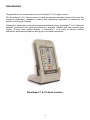
1
RomiApex™ A-15 APEX LOCATOR User Manual Please scan the QR code to view RomiApex A-15 additional instructions. Table of Contents Introduction 3 1. Indications for use 4 2. Warnings 4 3. Precautions 5 4. Package Contents 6 5. Getting Started 7 5.1 General 7 5.2 Installing / Replacing the Battery 7 5.3 Cable connection test 8 5.4 Device operation 9 5.5 Audio feedback 12 5.6 Automatic Shutdown 12 6. Demo mode 13 7. Maintenance, cleaning and sterilization 13 8. Troubleshooting guide 15 9. Certification 18 10. European Authorized Representative 18 11. Limited Warranty 18 12. Disclaimer 19 13. Technical Specifications 19 14. Electromagnetic declarations 20 15. Standard symbols 24 2 Introduction Congratulations on the purchase of your RomiApex™ A-15 Apex Locator. The RomiApex™ A-15 Apex Locator is a battery operated portable device which uses the frequency dependent impedance method and proprietary algorithms to determine the position of the apical foramen. Utilizing the advantages of its well proven patented technology, RomiApex™ A-15 offers the operator performing root canal treatments an accurate, reliable and user-friendly apex locator. Custom color graphic display of RomiApex™ A-15 helps to achieve optimal endodontic performance required during your root canal treatments. RomiApex™ A-15 Apex Locator 3 1. Indications for use RomiApex™ A-15 is an electronic device used for apex localization and working length determination during root canal treatment. RomiApex™ A-15 is indicated for patients who need to undergo root canal treatment, which requires precise determination of position of the dental file in the canal relative to the root apex. This product must only be used in hospital environments, clinics or dental offices by qualified dental personnel. 2. Warnings Read all instructions before operating this unit. The manufacturer accepts no liability for any damage resulting from improper use of this unit and/or for any purpose other than those covered by these instructions. U.S.A. Only: US Federal law restricts this unit to sale by or on the order of a dentist. As per Endodontic Standards of Care, always use a rubber dam when performing endodontic treatment. Do not use this unit with patients who have a pacemaker, as its effect has not been evaluated. RomiApex™ A-15 should not be used in the presence of flammable anesthetic mixtures with air or with oxygen or nitrous oxide. RomiApex™ A-15 must be stored in a dry place at temperatures between +10°C and +50°C (50ºF and 122ºF). Verify the measurements with a file and radiograph as abnormal canal anatomy or unusual canal morphology may cause inaccurate measurements (i.e. blocked canals, immature teeth). Do not use damaged file clips or any accessory because an inaccurate measurement could result. Do not use dry heat sterilization on the file clips and touch probes. The LCD screen readings 2.0, 1.75, 1.5, 1.25, 1.0, 0.75, 0.5 and 0.25 do not correspond to any actual distance in mm. They serve as a convenient reference to estimate the file tip position in relation to the apical foramen. NOTE: Sometimes the RomiApex™ A-15 reading and the x-ray image will not correspond. This can be due to the actual location of the apical foramen and inaccuracies of the x-ray angulation made before and during endodontic treatment. 4 3. Precautions Verify that the canal has been properly isolated and that there are no metallic restorations present which may contact the file. Normally RomiApex™ A-15 provides accurate measurements during foramen location in dry and wet canals, in presence of various electrolytic solutions (Sodium Hypochlorite, EDTA, saline, etc.). A #15 endodontic K-file #15 is the minimum recommended file size for apical foramen localization. However, smaller or larger files may be used when anatomically necessary. For convenience of use it is recommended that selected file will be about 5mm longer than the radiographic working length. Before measuring, check the accessories and verify good connectivity. RomiApex™ A-15 should not be dropped or subjected to other manners of impact or shock as this could result in malfunction of the device and voiding of the warranty. When disconnecting the lip clip, file clip or measuring cable, always grip the connectors. Do not pull directly on the wires to disconnect. Discard any old, damaged or leaky battery. Battery should be disposed of according to local codes and regulations. Battery cannot be disposed of as municipal waste within the European Union. Ensure the battery is installed with correct polarity. Do not immerse RomiApex™ A-15 unit. This may damage the device and will void the warranty. Only use recommended cleaning solutions on the device. See the “Maintenance, cleaning and sterilization” section 7 (page 13) for recommended cleaning and sterilization. The items which may contact the patient during intended use of the device (lip clip, file clip and touch probe) must be cleaned and sterilized before the first use and between patients to avoid the risk of cross-contamination. Care should be exercised when the RomiApex™ A-15 is used around devices emitting electromagnetic noise such as fluorescent lamps, film viewers, ultrasonic devices, radio frequency transmitters, cell phones, remote controls, or devices that radiate electromagnetic (EM) fields, areas where there are strong magnetic fields, or conditions where there is high static electricity (ESD). While the RomiApex™ A-15 has been built to withstand these conditions, EM and ESD fields may interfere with the device’s proper operation. If the RomiApex™ A-15 must be used under these conditions, take care to see that the device is operating normally (See manufacturer’s declaration of electromagnetic compatibility). 5 4. Package Contents Check the contents of the package before use: ● 1 RomiApex™ A-15 ● 1 Cradle ● 1 AAA 1.5V Alkaline Battery ● 1 Measuring cable ● 2 File clips ● 5 Lip clips ● 1 Touch probe ● 1 Screwdriver (for battery compartment) ● 1 User Manual 2 – File clips 1 - Measuring cable 5 - Lip clips 1 – Touch Probe 6 5. Getting Started 5.1. General There are two buttons on the front panel: On/Off Volume adjustment The measuring cable receptacle is located on the left side of the device. The battery compartment is located on back of the device. The RomiApex™ A-15 may be placed in or out of the cradle. The lip clip, the touch probe and the file clip should be sterilized before use. Please refer to “Maintenance, Cleaning and Sterilization” section 7 (page 13) for further information regarding maintenance of the RomiApex™ A-15. 5.2. Installing / Replacing the Battery The RomiApex™ A-15 is powered by a standard AAA size 1.5V alkaline battery (included). 5.2.1. To install/replace the battery, unscrew and remove the battery compartment cover on the back of the device (Fig. 1a). Remove the old battery (if one is present) using the built-in cloth strip; insert the new battery following polarity indications marked inside the battery compartment, (Fig. 1b), replace cover and tighten screw. Fig. 1a Fig. 1b Prior to battery replacement the device must be turned off. Before replacing the battery the measuring cable should be disconnected from the patient and removed from the RomiApex™ A-15 device. 7 5.2.2. When the battery level is low, the flashing Low Battery indicator will appear on the screen (Fig.2). RomiApex™ A-15 will continue normal operation even with a low battery, but the battery should be replaced before it loses all power. Fig. 2 5.3. Cable connection test Prior to each use, the RomiApex™ A-15 should be checked for functionality. The RomiApex™ A-15 has a connection test feature in order to check the cables. 5.3.1. Connect the measuring cable to the device. Connect the file clip and the lip clip to the measuring cable. Touch file clip contact to the lip clip. 5.3.2. “Connection” icon should appear on the display, indicating proper connection (Fig. 3). 5.3.3. If the symbol does not appear, the measuring cable or file clip should be replaced. Fig. 3 8 5.4. Device operation Do not use this unit with patients who have a pacemaker, as its effect has not been evaluated. 5.4.1. Place rubber dam prior to beginning endodontic treatment. 5.4.2. Obtain an initial radiograph and measure the distance between a reference point (i.e. incisal edge, peak of the cusp, etc.) to the image of the anatomical apex for the canal you will be working on. Subtract 0.5mm to establish your TEMPORARY working length. 5.4.3. Preflare the canal to partially remove canal contents and establish patency to your TEMPORARY working length. 5.4.4. To ensure proper measurements, verify that the canal is not completely dry or calcified. If needed, fill the canal with an electrolytic solution (i.e. Sodium Hypochlorite, Saline, etc.). 5.4.5. Depending on the size of the canal, insert a #15 hand K-file or other appropriate file into the canal. Fig. 4 5.4.6. Press the On-Off on the display. button to turn the device on. The initial image appears 5.4.7. Plug the measuring cable into the device and make sure that the cable icon appears on the display (Fig. 4). 5.4.8. Connect the lip clip and the file clip/touch probe to the measuring cable. 5.4.9. Put the lip clip onto the patient’s lip. 5.4.10. Connect the file clip to the file. The RomiApex™ A-15 will automatically detect that root canal measurement has started. If the electrical contact is good and the conductivity of the root canal is sufficient, the file icon inside the small tooth image will stop blinking and a double beep audio signal will sound. If there are no beeps, stop measurements, clean the file clip and the file, irrigate the canal, if required, and resume measurements. Make sure that irrigation solutions, blood or saliva don’t fill the access cavity. Dry the cavity if required before performing measurements. 9 5.4.11. Movement of the file inside the canal is reflected by the DOWN (Fig. 5) and UP (Fig. 6) arrows on the screen. 5.4.12. Continue to advance the file moving it smoothly in a watch-winding motion. As the instrument progresses toward the foramen, color segments inside the root canal image accompanied by audio signals with varied frequency will indicate the file’s progress. Numerical readings 2.0, 1.75, 1.5, 1.25, 1.0, 0.75, 0.5, 0.25, 0.0 (Foramen) or OVER appear under the tooth icon (Figs. 7-11). Erratic movement of the file may cause unstable readings. Fig. 5 Median Zone (Blue) Fig. 6 Beginning of the Apical Zone (Blue) Mid Apical Zone (Green) Fig. 7 Fig. 8 10 Fig. 9 5.4.13. Reaching the apical foramen (0.0) is indicated by a red color segment inside the root canal image (Fig. 10) and a constant audio tone. Determine the electronically obtained length using an endodontic ruler. To establish the working length, subtract 0.5 - 1.0mm from the electronic length. Foramen (red) (Red) Fig. 10 The red OVER indication accompanied by frequent beeps indicates that the file tip have progressed beyond the foramen into the periapical region - ‘Foramen over-instrumentation’ (Fig. 11). OVER (Red) Fig. 11 11 5.4.14. The file clip may be disconnected from the file and connected back during measurement without affecting normal device operation (for instance, when the file is changed to a larger number during root canal treatment or when another canal should be measured). In such cases the device detects automatically that the new measurement is initiated, the electrical contact and conductivity of the root canal are checked again and two beeps are sounded. Note: The RomiApex™ A-15 operates completely automatically. No manual adjustments are required. The RomiApex™ A-15 enables accurate localization of apical foramen independently of root canal conditions (dry, wet, with blood, pulp). In case of very dry canal or previous obturation (retreatment cases) you may use irrigation solution such as Sodium Hypochlorite, Saline, etc. to provide a conductive electrical environment. 5.5. Audio feedback The RomiApex™ A-15 is equipped with an audio indicator which is activated in parallel with progression of the file. This function enables monitoring of the file progression within the canal in the apical zone even without seeing the display. The volume can be adjusted to one of the four levels: mute, low, normal and high. The adjustment is performed by successive pressings of the volume key . 5.6. Automatic Shutdown The RomiApex™ A-15 automatically shuts off after 5 minutes without use. In order to prolong the battery life, after completing the measurements, it is recommend switching the device off by pressing the On/Off key . 12 6. Demo mode The built-in Demo mode is available to demonstrate operation of the device. 6.1. Disconnect the measuring cable from the device and turn the device off. 6.2. To start Demo mode, press and hold the On/Off key for about 1 sec. until the second beep sounds and “Demo” indication appears on the screen. 6.3. During Demo cycle the operating sequence of the device is shown on the screen. Press On/Off key to pause the simulation; press On/Off key again to resume. 6.4. When Demo cycle is completed, it is repeated automatically until interrupted by the operator. 6.5. To exit Demo mode press and hold the On/Off key sounds. for about 1 sec. until a beep Note: If measuring cable is inserted into the device receptacle during Demo cycle, RomiApex™ A-15 exits Demo mode and switches automatically to regular operation mode. 7. Maintenance, Cleaning and Sterilization 7.1. General The device does not contain user serviceable parts. The service and repair should be provided by factory trained service personnel only. All objects that were in contact with potentially infectious agents should be cleaned after each use: Lip clip, file clip and touch probe should be disinfected and sterilized by autoclaving before the first use and between treatments. Please follow “Disinfection and sterilization procedure” described in next section. Measuring cable, the device and its cradle should be cleaned using tissue or soft cloth impregnated with aldehyde free disinfecting and detergent solution (a bactericidal and fungicidal). The measuring cable should not be autoclaved. Use of agents other than specified above may cause damage to the equipment and its accessories. 13 7.2. Disinfection and sterilization procedure # Operation Instructions 1 Preparation at the point of use prior to processing No particular requirements. 2 Preparation for decontamination/ preparation before cleaning No particular requirements. 3 Cleaning: Automated The accessories are not intended for automated cleaning. Cleaning: Manual Clean the accessories with an appropriate brush or towel soaked in a disinfectant solution. - The file clip should be pressed and released several times during cleaning to assure all debris is removed. - After cleaning, there should be no visible debris on the accessories. 5 Disinfection Soak the accessories in a disinfectant solution that contains a proteolytic enzyme if possible. Rinse accessories thoroughly in running water. - Follow manufacturer’s instructions on the disinfectant (concentration, immersion time, etc.). - Do not use disinfectant containing aldehyde, phenol or any products which may damage the items. 6 Drying No particular requirements. 7 Maintenance, inspection and testing of the accessories No particular requirements. 4 8 9 Details and Warnings Packaging Pack the devices in sterilization pouches. Sterilization - Steam sterilization at 135°C (275°F) for 10 minutes in table top, N-type autoclave. 14 - Check the expiration date of the pouch given by the manufacturer to determine the shelf life. - Use packaging which is resistant up to a temperature of 141°C (286°F). - Follow maintenance and operation procedures of the autoclave provided by the manufacturer. # Operation Instructions Details and Warnings - Drying time after sterilization – 30 minutes. 1 0 Storage Keep devices in sterilization packaging in a dry and clean environment. - The only sterilization parameters to be used are those that have been provided in this Manual. Sterility cannot be guaranteed if packaging is open or damaged (check the packaging before using the instruments). 8. Troubleshooting Guide Problem Possible Solution Blank screen after use - The device automatically shuts down after 5 minutes without use - press the On-Off button to turn the device on. - Battery is completely dead – replace with fresh battery ensure the battery is installed with proper polarity. Realign if necessary. - Device has malfunctioned – contact your supplier. Display showing no progression of the file towards the apical area/foramen - If already in use, this may indicate a poor connection check all connections and ensure lip clip is contacting the oral mucosa and file clip is clean and free of debris - Fill the canal with an electrolytic solution, if required (i.e. Sodium Hypochlorite, Saline, etc.). - The endodontic file is not touching the internal canal walls - replace the file using a larger diameter file. - If the behavior persists, the measuring cable or file clip may need to be replaced and/or the device should be sent in for service – contact your supplier. The cable icon does not appear - Make sure the measuring cable is properly connected. - If the behavior persists, the measuring cable may need to be replaced and/or the device should be sent in for service – contact your supplier. The File icon keeps blinking - The file clip is not properly connected with the endodontic file. - Check all connections and ensure lip clip is contacting the oral mucosa and file clip is clean and free of debris. - If the behavior persists, the measuring cable may need to be replaced and/or the device should be sent in for service – contact your supplier. The connection icon does not appear - Try connecting another file clip to the measuring cable. 15 Problem when touching the file clip and the lip clip Possible Solution - If the behavior persists, the measuring cable may need to be replaced and/or the device should be sent in for service – contact your supplier. The OVER - The file tip has progressed beyond the apical foramen – move the file back until the OVER indication disappears. indication appears accompanied by frequent audio beeps No audio tones - The volume was adjusted to “mute” - press the volume key until the desired volume level is reached. - Device has malfunctioned - contact your supplier. Problem Possible cause Solution 1. File position indication is unstable, erratic results. Is second electrode (lip clip) making good contact with mucosa? Make sure the lip clip makes good contact with the oral mucosa Is the file clip dirty? Clean the file clip with Ethanol 7080% vol. Is blood or other fluids over flowing the access cavity of the tooth? If blood or other fluids are overflowing the access cavity they may create a conductive path outside the canal and cause incorrect measurements (“OVER” indication, unstable readings, etc.). Check the rubber dam isolation, use OraSeal® Caulking or Putty to repair rubber dam leaks. You may use ViscoStat® or Astrigedent® for control the gingival tissue bleeding. Clean and dry the pulp chamber and tooth crown thoroughly. Is the canal filled with blood, or chemical solutions? The canal length indicator may suddenly swing when it breaks the surface of fluids inside the canal, but it will return to normal as the file is advanced toward the apex. Is the tooth surface covered with tooth debris, smear layer or chemical solutions? Clean entire tooth surface. Is the file touching the gingival tissue? This might lead to incorrect readings or cause the canal length indicator suddenly to jump all the way to the “OVER” position. 2. Measurements are too short or too long; poor accuracy. 16 Problem Possible cause Solution Is there vital inflamed pulp tissue left inside the canal? If a large amount of vital inflamed pulp tissue is left inside the canal, particularly in wide canals such as upper incisors and canines, it may cause incorrect measurements. Is the file touching metal prosthesis or filling? Touching a metal prosthesis of filling with the file may create a conductive path outside the canal and cause incorrect measurements (“OVER” indication, unstable readings, etc.) Are proximal surfaces infected with caries? Deep caries may create a conductive path outside the canal and cause incorrect measurements (“OVER” indication, unstable readings, etc.) Are there external resorption or is the tooth fractured? The canal length indicator may jump to “OVER” position when it reaches a resorption area or a fractured root tooth. Does a broken crown cause incorrect measurements? Build up an insulating barrier to isolate the file from the crown. Is there a lesion at the apex? A chronic lesion can destroy the apical foramen through resorption and cause incorrect measurements. Is the file clip holder broken or dirty? Replace or clean the file clip. If the problem persists, please contact your supplier. 17 9. Certification The RomiApex™ A-15 complies with the following standards: IEC 60601-1 (Safety) and IEC 60601-1-2 (Electromagnetic compatibility), including conducted and radiated immunity tests as specified for equipment of Group 1 Class B. The RomiApex™ A-15 is covered by the “CE Marking of Conformity” certificate. The device bears the following CE identification mark: 0483 10. European Authorized Representative European Authorized Representative who has been empowered to enter into commitments on our behalf: Obelis s.a Bd. Général Wahis 53 1030 Brussels, BELGIUM Tel: +(32) 2.732.59.54 Fax: +(32) 2.732.60.03 E-Mail: [email protected] 11. Limited Warranty RomiApex™ A-15 is warranted for 24 months from the date of purchase**. The accessories (Measuring cable, file clips, lip clips, touch probe) are warranted for 6 months from the date of purchase. The warranty is valid for normal usage conditions. Any damage caused by accident, abuse, misuse, or as a result of service or modification other than by a person authorized by the manufacturer will render the warranty void. The warranty is in lieu of any other warranty expressed or implied. Any modifications made to the equipment without explicit approval from Romidan Ltd. voids warranty obligations and poses a potential safety threat to both operator and patient. **With sales receipt indicating the date of sale to the dentist. 18 12. Disclaimer The manufacturer, its representatives and its dealers shall have no liability or responsibility to customers or any other person or entity with respect to any liability, loss or damage caused or alleged to be caused directly or indirectly by equipment sold or furnished by us, including, but not limited to, any interruption of service, loss of business or anticipatory profits, or consequential damages resulting from the use or operation of the equipment. The manufacturer reserves the right to implement changes and modifications of the product at any time, to revise this publication and to make changes in the contents hereof without obligation to notify any person of such changes, modifications or revisions. 13. Technical Specifications The RomiApex™ A-15 belongs to the following category of medical devices: - Internally powered equipment (AAA 1.5V alkaline battery) Type BF applied parts Not suitable for use in presence of flammable anesthetic mixtures with air, oxygen or nitrous oxide Continuous operation Ingress of liquids – not protected The device is intended for indoor use only Environmental conditions during transportation: temperature: –20ºC to +60ºC (0 to 140ºF); relative humidity: 10% to 90%, non-condensing RomiApex™ A-15 is intended for use in electromagnetic environment specified for equipment of Group 1 Class B. Specifications: Dimensions: Weight: Type of screen: Screen dimensions: Supply: W55 x H92 x T16 mm 100 gr. Custom Color Graphic LCD 51 x 38 mm AAA 1.5V alkaline battery 19 14. Electromagnetic declarations (IEC 60601-1-2) Table 1: Guidance and Manufacture’s Declaration for Electromagnetic Emissions The RomiApex™ A-15 is intended for use in the electromagnetic environment specified below. The customer or user should ensure that it is used in such an environment. Emissions Test Compliance RF emissions EN 5011 (European Norm equivalent to CISPR 11) Group 1 RF emission EN 5011 (European Norm equivalent to CISPR 11) Class B Harmonic emissions IEC 61000-3-2 NA Voltage fluctuations/flicker emissions IEC 61000-3-3 NA 20 Electromagnetic environment guidance The RomiApex™ A-15 uses low voltage and low current, electrical and electromagnetic energy only for its internal functions. Therefore, its RF emissions are very low and are not likely to cause interference in nearby electronic equipment. The RomiApex™ A-15 does not have AC power input or AC power output, therefore testing for this is not applicable. (IEC 60601-1-2) Table 2: Guidance and Manufacture’s Declaration for Electromagnetic Immunity The RomiApex™ A-15 is intended for use in the electromagnetic environment specified below. The customer or user should ensure that it is used in such an environment. IMMUNITY test IEC 60601 test level Compliance level ± 6kV contact Electrostatic discharge (ESD) IEC 61000-4-2 ± 8 kV air ± 6kV contact Electrical fast transient/burst IEC 61000-4-4 ± 2 kV for power supply lines ± 1 kV for input/output lines Not applicable Not applicable Surge IEC 61000-4-5 ± 1 kV line to line Not applicable ± 2 kV line to earth Not applicable <5% U (>95% dip in U for 0.5 cycle) 40% U (60% dip in U for 5 cycles) 70% U (30% dip in U for 25 cycles) <5% U (>95% dip in U for 5 s) Not applicable Voltage dips, shorts, interruptions and variations on the power supply input lines IEC 61000-4-11 Power frequency (50/60 Hz) magnetic field IEC 61000-4-8 3 A/m ± 8 kV air Not applicable Electromagnetic environment guidance The RomiApex™ A-15 has built in ESD protection. The physical environment should be restricted to the following: 1. Humidity range: 10% - 90% 2. Temperatures range: 10 C - 42 C The RomiApex™ A-15 does not have AC power input or AC power output, therefore testing for this is not applicable. Interconnecting cables are not longer than 3m, therefore testing is not applicable. The RomiApex™ A-15 does not have AC power input or AC power output, therefore testing for this is not applicable. Not applicable Not applicable 3 A/m Power frequency magnetic fields should be at levels characteristic of a typical location in a typical, residential, commercial, hospital, or military environment. NOTE: U is the AC. mains voltage prior to application of the test level Note 1: The RomiApex™ A-15 is not equipped with any ports or any accessible I/O lines. Note 2: The RomiApex™ A-15 may be susceptible to strong magnetic fields or static electric fields higher than the limits specified in testing, which could interrupt normal operation. If there is a reason to believe that this type of interference has occurred, simply remove and re-insert the batteries and the unit should reset. 21 (IEC 60601-1-2) Table 4: Guidance and Manufacture’s Declaration for Electromagnetic Immunity for non-life support systems The RomiApex™ A-15 is intended for use in the electromagnetic environment specified below. The customer or user should ensure that it is used in such an environment. IMMUNITY test IEC 60601 test level Compliance level Conduction RF IEC 61000-4-6 3 Vrms 150 kHz to 80 MHz 3 Vrms 150 kHz to 80 MHz Radiated RF IEC 61000-4-3 3 V/m 80 MHz to 2.5 GHz 3 V/m 80 MHz to 2.5 GHz Electromagnetic environment guidance RomiApex™ A-15 is not affected by portable and mobile RF communications equipment in close proximity. There is no recommended separation distance from transmission sources. RomiApex™ A-15 will operate safely and effectively near cell towers and radio/TV transmitters. Note 1: The RomiApex™ A-15 may be susceptible strong magnetic fields or static electric fields higher than the limits specified in testing, which could interrupt programming. If there is a reason to believe that this type of interference has occurred, simply re-insert the battery and the unit should reset. 22 (IEC 60601-1-2) Table 6: Recommended separation distances between portable and mobile RF communications equipment and not life supporting equipment The RomiApex™ A-15 is intended for use in an electromagnetic environment in which radiated RF disturbances are controlled. The customer or the user of the RomiApex™ A-15 can help prevent electromagnet interference by maintaining a minimum distance between portable and mobile RF communications equipment (transmitters) and the RomiApex™ A-15 as recommended below, according to the maximum output power of the communications equipment. Separation distance according to frequency of transmitter Rated maximum output power of transmitter W m 150 kHz to 80 MHz d = 0.35 80 MHz to 800 MHz P d = 0.35 P 800 MHz to 2.5 GHz d = 0.7 0,01 0,04 0,04 0,07 0,1 0,11 0,11 0,22 1 0,35 0,35 0,7 10 1,1 1,1 2,2 100 3,5 3,5 7 P For transmitters rated at a maximum output power not listed above, the recommended separation distance d in metres (m) can be estimated using the equation applicable to the frequency of the transmitter, where P is the maximum output power rating of the transmitter in watts (W) according to the higher frequency range applies. Note 1: At 80 MHz and 800 MHz, the separation distance fort the higher frequency range applies. Note 2: These guidelines may not apply in all situations. Electromagnetic propagation is affected by absorption and reflection from structures, objects and people. 23 15. Standard symbols On the device labeling appear standard symbols as follows: Special disposal of waste electrical and electronic equipment 1.5V Follow instructions for use Type BF applied part Direct current SN Manufacturer Caution: Federal law restricts this device to sale by or on the order of a physician or licensed dental practitioner 24 Serial Number RomiApex A15 Rev. 07 – 04/14 Manufacturer: Romidan Ltd. 5 Simcha Holzberg St., 55022 Kiryat Ono, Israel Email: [email protected] www.romidan.com