1
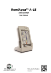
MANUAL USE AND MAINTENANCE
DEVICE FOR HOME USE FOR THE
TREATMENT OF DRINKING WATER
WITH REVERSE OSMOSIS SYSTEM
WAS V01 e WAS V02
Made in Slovenia
TABLE OF CONTENTS
GENERAL PART
WATER TREATMENT FOR HUMAN CONSUMPTION
CHARACTERISTICS OF FILTRATION SYSTEMS
Pag. 3
Pag. 4
TECHNICAL DATA
TREATMENT OF WATER WITH REVERSE OSMOSIS SYSTEM WAS
TECHNICAL DATA WAS V01
TECHNICAL DATA WAS V02
HOW ARE MADE
Pag. 7
Pag. 9
Pag. 11
Pag. 13
INSTALLATION
PRE-INSTALLATION WARNING
INSTALLATION
THE WATER TESTS
PROBLEMS AND SOLUTIONS
Pag. 15
Pag. 17
Pag. 20
Pag. 24
MAINTENANCE
SPARE PARTS
INSTRUCTIONS FOR THE ORDINARY MAINTENANCE
INSTUCTION FOR THE EXTRAORDINARY MAINTENANCE
SANITIZATION
Pag. 25
Pag. 27
Pag. 29
Pag. 32
DOCUMENTS
WARANTY
CERTIFICATES AND AWARDS
DISPOSAL END USE WAS
STATEMENTS OF INSTALLATION
MAINTENANCE REGISTER
Pag. 33
Pag. 34
Pag. 35
Pag. 36
Pag. 38
WHERE TO APPLY
TECHNICAL ASSISTANCE CENTRE
NOTES
Pag. 39
Pag. 40
Nerviano, 2014-08-23
Manual use and maintenance WAS V01 – V02
Pag. 2 of 40
WATER TREATMENT FOR HUMAN CONSUMPTION
IMPORTANT INTAKE OF HEALTHY AND PURE WATER IN THE HUMAN BODY
Even today, many people are lagging health benefits caused by a problem too often ignored: the
lack of pure water within your body.
The man is made up of 70% water: it is therefore evident that all the cells, body tissues and the
circulatory system need pure water to function correctly.
QUALITY CONTROL
The quality of the water supplied by aqueducts is ensured by a number of external controls as well
as internal to the aqueducts themselves the responsibility of local health services (ASL).
The parameters to be analyzed and the limit values are established by the law. For non-harmful
substances and various other water features parameter “indicators” exist. If these are not
respected, the law requires that the local health authorities valuate whether it is appropriate to
have “measures to restore water quality.”
It is important to note that the aqueduct is held responsible for the quality of the water up to our
house but not to the tap. Which means that the internal piping of the houses and the presence of
tanks with autoclave could change the water quality, in particular regarding the presence of
certain metals.
AND WHEN THE LIMITS ARE EXCEEDED OR WHEN WE NEED WATER EVEN MORE PURE?
We must have a device for water treatment.
Nerviano, 2014-08-23
Manual use and maintenance WAS V01 – V02
Pag. 3 of 40
CHARACTERISTICS OF FILTRATION SYSTEMS
In filters of reverse osmosis water is forcibly conducted, arising its pressure, through a spillproof
membrane thoughout which only certain substances in certain quantities can pass. It is the most
efficient filtration system, acts on heavy metals, nitrates and other undesirable substances, it also
acts on the water hardness.
Nerviano, 2014-08-23
Manual use and maintenance WAS V01 – V02
Pag. 4 of 40
THE REVERSE OSMOSIS
The principle of osmosis is known from the early years of the last century, it is the principle that
the mineral salts liquid retention winning atmospheric pressure, even through obstacles that may
provide resistance, such as semi-permeable materials.
This principle allows the cells of our body to eat properly, in fact, they are covered with a
semipermeable membrane, which allows you to filter the food and minerals they need and
excrete substances not used. In nature, osmosis occurs, when two solutions of varying salt
concentration, are separated by a semipermeable membrane: the solution with a lower
concentration of salt passes through the membrane and goes to dilute the solution with increased
salt concentration (Figure A).
By reversing this process, you get the reverse osmosis: pushing pressure with a saline solution
against a semipermeable membrane, separation is obtained of the pure water from the impurities
that are not able to pass through the micropores of the membrane (figure B).
The reverse osmosis principle, therefore, is to force the water through a semipermeable
membrane, in order to separate the substances of organic and inorganic origin dissolved in it.
While having micropores, the reverse osmosis membrane should not be considered as a common
filter. The traditional filter has a filtration degree of the lowest and therefore does not allow the
arrest of inorganic substances and is designed to retain the impurities within it. The reverse
osmosis membrane, however, besides having a higher degree of filtration, is constructed in such
manner that the bacterial substances that do not pass through it is expelled.
Nerviano, 2014-08-23
Manual use and maintenance WAS V01 – V02
Pag. 5 of 40
SOME TIPS FOR CHOOSING THE RIGHT REVERSE OSMOSIS FILTRATION SYSTEMS
The reverse osmosis devices must observe the following conditions:
a) the operation must be fully automatic
b) there must be a device capable of ensuring the non returning of the water to the exhaust;
c) membranes and other components of the system in contact with the water must meet the
requirements prescribed for materials intended to come into contact with food and beverage;
d) if a collection tank of the downstream treatment is provided, the plant must be equipped with a
system for continuous disinfection, preferably chlorine or its compounds, or by the use of ray
lamps U.V.;
e) when the arrangements for continuous disinfection are different from those above-report, such
rules must be approved by the Ministry of Health on the basis of compliance with the
experimental protocol.
f) in the pretreatment of the waters covered by the process of reverse osmosis activated carbon
filters and microfilters are allowed;
g) substances used in retreatment must meet the standards requirements of purity required for
usage in the food or drinking water treatment.
Nerviano, 2014-08-23
Manual use and maintenance WAS V01 – V02
Pag. 6 of 40
TREATMENT OF WATER WITH REVERSE OSMOSIS SYSTEM WAS
IN WHAT WAY IS IT DIFFERENT FROM OTHER REVERSE OSMOSIS DEVICES?
• WAS reverse osmosis devices are a Slovenian product
• The materials used are of the highest quality
• Are compact and of modern design
• Electronic program for operation and quality of water control
• Direct filtering system without collection tanks thanks to high performance pump
• Automatic wash system in case of not using the water purifier prevents the formation of bacteria
• Equipped with water-stop system that blocks any loss
• Sound and light signals to alert in case of malfunction
• Signals indicating the need for filters replacement
• Reliable operation
• Simple maintenance thanks to quick couplings
MORE ABOUT THE V02 VERSION
• Water temperature can be regulated (+8°C)
Nerviano, 2014-08-23
Manual use and maintenance WAS V01 – V02
Pag. 7 of 40
DIMENSIONS
FILTER WITH WAS
Inlet water is filtered by means of:
• pre-filter ( sand, mud, sediments )
• activated carbon filter ( chlorine, poisons that bind with activated carbon )
• double osmosis filters ( heavy metals, pesticides, nitrates, asbestos, bacteria, viruses.. )
Water is filtered when needed.
The high pressure pump of the device provides 1,2 l/minute purified water just with the simple
press of the button.
Reverse osmosis filters rinse themselves.
We get 0,6 l of purified water out of 1 l tap water through the special tap included in the
installation kit.
The rest of the water goes down the drain along with the impurities.
The osmosis filter life is 4 to a maximum 7 years with normal use and regular maintenance.
Device electronic parts provide sound and light signals for:
• the quality of water we use,
• use of filters,
• lack of water,
• water leak – Water Stop - the water flow stops.
Nerviano, 2014-08-23
Manual use and maintenance WAS V01 – V02
Pag. 8 of 40
TECHNICAL DATA WAS V01
WAS V01 is an appliance for domestic use for the treatment of drinking water. It is based on the
reverse osmosis principle , the principle through which uses a semipermeable membrane in order
to reduce the salt content of the water. WAS V01 is thus presented as the ideal to improve the
organoleptic characteristics of the drinking water supplied by the public service . It is able to
produce water of high quality for various uses , not only for drinking but also for washing
vegetables and for cooking.
WAS V01 consists of a box and a lid galvanized epoxy powder coated steel.
The front panel is made of plastic with LED light bar to display the permeate conductivity and
durability of filters, two lights for the reporting of various alarms purifier and an inside button (can
be operated with a small nail ) for displaying the LED bar.
The rear panel has externally in the power supply with built-in fuse holder and two fittings for the
permeate outlet and discharge, the adjustment screw by-pass and the nipple of the solenoid water
inlet . First , there is a main switch for the light switching on and off.
Inside are housed :
- Solenoid valve inlet water supply.
- Pre-sediment filter
- Activated carbon filter
- Two osmosis membranes Filmtec ( contained in two vessel )
- By-pass valve mixing water
- A minimum pressure n.a. for the protection of the feed pump .
- A 180-watt electric motor
- A rotary vane pump
- An electronic card for operation.
- A probe for the measurement of the conductivity.
- Sensor reporting any loss of water (Water Stop).
All materials in contact with water (pipe fittings , pipes , containers, etc.), are constructed in
material for food use.
Nerviano, 2014-08-23
Manual use and maintenance WAS V01 – V02
Pag. 9 of 40
DIMENSIONS
FEATURES
WAS V01 is compact , controlled by the computer , positioned below the sink .
- Output capacity is up to 1,700 liters (456 gallons ) of filtered water a day
- No tank, direct flow
- Display of conductivity measurements and filter consumption LED
- Buzzer for alarm
- Power supply voltage 220V, 50Hz
- Power consumption: 3A – 300W
REQUIREMENTS FOR THE SMOOTH FUNCTIONING
- Pressure of water supply: from 1 to 4 bar
- Scope of supply: minimum 120 l / h
- Working pressure: max 10 bar downstream of the pump
- Working Range: up to 100 l/h
- Ambient temperature: +5 ° C to +35 ° C
- Water temperature: from +5 ° C to +35 ° C
- Relative humidity: 95% non-condensing environment
WARRANTY
- Certified by Institute of Public Health
- CE certified
- 24 month warranty
Nerviano, 2014-08-23
Manual use and maintenance WAS V01 – V02
Pag. 10 of 40
TECHNICAL DATA WAS V02
WAS V02 is an appliance for domestic use for the treatment of drinking water. It is based on the
reverse osmosis principle , the principle through which uses a semipermeable membrane in order
to reduce the salt content of the water. WAS V02 is thus presented as the ideal to improve the
organoleptic characteristics of the drinking water supplied by the public service . It is able to
produce water of high quality for various uses , not only for drinking but also for washing
vegetables and for cooking.
WAS V02 consists of a box and a lid galvanized epoxy powder coated steel.
The front panel is made of plastic with LED light bar to display the permeate conductivity and
durability of filters, two lights for the reporting of various alarms purifier and an inside button (can
be operated with a small nail ) for displaying the LED bar.
The rear panel has ela externally in the power supply with built-in fuse holder and two fittings for
the permeate outlet and discharge, the adjustment screw by-pass and the nipple of the solenoid
water inlet . First , there is a main switch for the light switching on and off,
Inside are housed :
- Solenoid valve inlet water supply
- Pre-sediment filter
- Activated carbon filter
- Two osmosis membranes Filmtec ( contained in two vessel )
- By-pass valve mixing water
- A minimum pressure n.a. for the protection of the feed pump
- A 180-watt electric motor
- A rotary vane pump
- An electronic card for operation.
- A probe for the measurement of the conductivity.
- Sensor reporting any loss of water (Water Stop).
All materials in contact with water (pipe fittings , pipes , containers, etc.), are constructed in
material for food use.
Nerviano, 2014-08-23
Manual use and maintenance WAS V01 – V02
Pag. 11 of 40
DIMENSIONS
FEATURES
WAS V02 is compact , controlled by the computer , positioned below the sink .
- Output capacity is up to 1,700 liters (456 gallons ) of filtered water a day
- No tank, direct flow
- Display of conductivity measurements and filter consumption LED
- Buzzer for alarm
- Power supply voltage 220V, 50Hz
- Power consumption: 3A – 300W
REQUIREMENTS FOR THE SMOOTH FUNCTIONING
- Pressure of water supply: from 1 to 4 bar
- Scope of supply: minimum 120 l / h
- Working pressure: max 10 bar downstream of the pump
- Working Range: up to 100 l / h
- Ambient temperature: +5 ° C to +35 ° C
- Water temperature: from +5 ° C to +35 ° C
- Relative humidity: 95% non-condensing environment
WARRANTY
- Certified by Institute of Public Health
- CE certified
- 24 month warranty
THE ABOUT CHARACTERISTICS ARE IDENTICAL TO VERSION V01 MORE OVER THE VERSIONE V02
HAVE:
The water cooling system
Nerviano, 2014-08-23
Manual use and maintenance WAS V01 – V02
Pag. 12 of 40
HOW ARE MADE
PANEL CONTROL
LED light control for status signalisation
WITH HIGH PERFORMANCE PUMP THE COLLECTION TANK IS NOT NECESSARY BEFORE
DOWNSTREAM PROCESSING
The WAS devicess are without collection tank and this allows an increase of the flow of purified
water thus ensuring a constant and elevate flow, in fact, while in systems with tank the flow is
generated by the pressure in the tank itself, in the WAS devices the flow is generated by a pump
with high performance.
Also, the stagnant water contained in the tank can sometimes accumulate germs, bacteria, etc. for
this reason, the systems with the collection tank must necessary have the UV lamp.
The WAS devices being direct production plants have many advantages including:
- Absolute bacteriological purity
- No the water heating due the U.V. lamp because it is not necessary,
- Do not need replace the U.V. lamp every year, with savings on maintenance costs.
Nerviano, 2014-08-23
Manual use and maintenance WAS V01 – V02
Pag. 13 of 40
NOTE
The WAS V01 as well as the WAS V02 are supplied with pre-filter inside the chassis (see figure left),
you can still order without pre-filter in which case the interior will look like in the figure on the left.
LESS WASTE WATER
The reverse osmosis devices of old conception produce a considerable amount of waste water as
resulting of there osmosis process.
The WAS devices are made so as to minimize the amount of waste water.
SELF-CLEANING SYSTEM OSMOTIC MEMBRANE
A characteristic of the WAS devices consists in washing the osmotic membrane through a flow of
water at high pressure.
During the filtration the water passes into the osmotic membrane which retains all the impurities,
when the amount of salts and waste substances exceeds the allowed level, the membrane no
longer has the same purifying capacity that had initially. in this case the automatically cleaning
system intervenes, the substances trapped in the osmotic membrane are so discharged thus
restoring its efficiency.
COMPUTER CONTROL
The WAS devices are equipped with computers capable of controlling the entire process of
filtration.
Computer control of water quality, pressure control, water consumption counting, etc.
Nerviano, 2014-08-23
Manual use and maintenance WAS V01 – V02
Pag. 14 of 40
PRE-INSTALLATION WARNING
Installation devices for home use for treatment of drinking water with reverse osmosis system
WAS
- Simply press the button of the tap supplied in the installation kit to use the device,
- Installation takes on average an hour,
- You can install your device under the kitchen sink.,
- The device is constructed in such a way, that it is easier to carry out reset (just CLICK),
- Sound and light signals inform us of any abnormalities.
WAS V01 and V02 are easy to use and most importantly it is completely automatic. Once installed
and calibrated, simply turn on the main power switch and press the button on the faucet, let the
water run for a few seconds before you remove it. Once you have taken the amount of water
needed, press the button on the faucet to stop dispensing.
INSTALLATION KIT
The supply includes what is necessary for the first installation , piping, drain hose fitting water tap ,
power cord electric current.
Of course the kit with installation, above , is scheduled for installation in standard and that is to
have close to about 1.5 m an electrical outlet and that there is a water shut off valve with 3/ 4 ”
typical attack for dishwasher / washing machines.
RECOMMENDATIONS
- The manual has been prepared to provide you , as clearly as possible all the information required
for installation , use and maintenance of the WAS device.
– Before using the appliance read , in all its parts , the user manual and maintenance , knowledge
of the information and instructions contained in this manual , are essential for the proper
installation and proper use of the device by the user.
– WAS has been designed and built with mechanical and electrical safety measures to protect you
from physical , is the responsibility of the purchaser to ensure that all users are aware of the
information and recommendations in this manual .
- Only original spare parts is guaranteed by the functional reliability and performance optimization
of the device; applying changes , supplies or devices of any kind to the equipment, unless
specifically provided for in the manual, are to be considered total responsibility of the user.
Nerviano, 2014-08-23
Manual use and maintenance WAS V01 – V02
Pag. 15 of 40
WARNINGS
- Make sure that the hot water cannot enter into the device (28°C max);
– Make sure that the heater is not used with water under 5°C or in areas subject to frost;
– The water supply pressure must be between the maximum of 0.4 MPa (4 bar) and the minimum
of 0.1 MPa (1 bar) . For pressures above 0.4 MPa or in case of water hammer , it is essential a
pressure regulator ;
– Never operate the unit in the absence of water, what could destroy the pump ;
– In case of continuous operation can take place on the electric heat that will stop the engine from
overheating until you will not be cooled again ;
– For a perfect preservation membranes are kept in a liquid bacteriostatic , do not use so the first
water produced from a new plant or where it replaced the osmotic membrane , but let it slide for
about 30 minutes ;
– Leave a liter anyway scroll after each stop ( over 24 h ), and is of higher quality than that
remained in osmotic membrane;
– For long periods so it is advisable to sanitize the system and slide for at least 10 – 15 minutes the
water.
GENERAL INFORMATION
- Always remove the power cord from the outlet before carrying out any maintenance work or
cleaning equipment.
– Before connecting the power cord to the power outlet , ensure that the mains voltage is the
same as that stated on the label . Voltage dips , higher or lower than 10% of the nominal value ,
can damage the electrical parts of the equipment.
– This appliance must be used only for what it was designed, ie for the treatment of water for
drinking purposes from the public water supply.
– To clean the device does not use corrosive products , acids, steel wool or steel brushes.
– Do not wash the machine with direct water jets.
– The manufacturer disclaims any liability whatsoever for any damage to persons or things caused
by non-observance of the instruction provided in the manual.
Nerviano, 2014-08-23
Manual use and maintenance WAS V01 – V02
Pag. 16 of 40
INSTALLATION
BEFORE INSTALLATION
POSITIONING
- Before proceeding with the installation, check that there is enough space. (eg. at least 500mm
deep)
CONTROL FILTERS
- Rinse well, the activated carbon filter before installing it.
- The reverse osmosis membranes contain a preserving agent for the storage and transportation.
Clean the membrane by this agent before using the water produced.
INSTALLATION FAUCET
- Check before you make the hole in the floor on the underside of the sink if there is scope for
tightening and connections to the faucet with the supplied accessories.
- Warning in case of semi-precious stones (eg. granite) turn to specialized companies.
- In case of use of a three-way mixer follow the directions of the manufacturer of the faucet.
ELECTRICAL CONNECTION
- Verify that there is a socket 220 V – 50 Hz in the immediate vicinity of the device, where to insert
the power plug, it has a grounded and connected to a life saving device.
Nerviano, 2014-08-23
Manual use and maintenance WAS V01 – V02
Pag. 17 of 40
HYDRAULIC CONNECTION
- WATER INLET - Blue pipe with junction 3/4″ to be connected to the water shut off valve.
- PURIFIED WATER OUTLET - Blue pipe Ø 6
- DRAIN
- Red pipe Ø 6
INSTALLATION PROCEDURE
- Install a shut-off valve ¾ ” (faucet for washing machine ) for power , where it will be installed at
the device. Make sure that the feed device is coming from the public water supply.
- Drill holes in the floor where it will be installed on the faucet .
- Attach the faucet to the plan.
- Remove the screws and the cover of the device.
- Tighten the two ends of the feeding tube blue , supplied , the correct fitting of the shut-off valve
and solenoid valve.
- Connect the blue hose Ø 6 , supplied , to the tap and the outlet connector of the permeate
through the proper fittings .
- Perform a 6 mm hole on the exhaust pipe of the sink , slide on the exhaust pipe of the plant the ”
tie ” and tighten not too sure that the tube and the hole coincide. Connect the intake hose Ø 6
red, supplied through the proper fittings .
Nerviano, 2014-08-23
Manual use and maintenance WAS V01 – V02
Pag. 18 of 40
OPERATION
7.1 Connect all the pipe , pushing it deeply tubes red and blue on the quick couplings ( red and
blue on the drain fitting on the fitting of the permeate ) and tighten the fittings ¾ ” on the solenoid
valve and the shut-off valve.
7.2 Check any water leaks
7.3 Connect the water power cord a the device.
7.4 Slowly open the valve on the water.
WARNING DO NOT OPERATE THE DEVICE BEFORE YOU OPEN THE FAUCET WATER INLET
7.5 Connect the power cord into the wall outlet , turn on the power switch on the device and
crush the switch on the faucet .
7.6 Allow water to run for 15 minutes and check that there are no water leaks inside and outside
of the equipment.
7.7 Take from the faucet a water sample and perform the measurements. see the water test
7.8 Intervening with a screwdriver on the by-pass valve on the back of the system and make
appropriate adjustments : Turn counterclockwise to increase the percentage of untreated water to
be mixed to permeate, turning clockwise to decrease this percentage . For each adjustment repeat
the measurements .
7.9 After reaching the desired mix , put the lid on the water purifier and tighten the screws.
ADJUSTMENTS
I WAS devices are equipped with by-pass valve ( section 7.8 ) for adjusting the residual salinity and
hardness as required by Ministerial Decree 443 of December 1990.
The measurement must be performed with a specific conductivity , various measures must be
taken by discarding the overhead product, ( see section tests).
WAS is now ready for use.
Nerviano, 2014-08-23
Manual use and maintenance WAS V01 – V02
Pag. 19 of 40
THE WATER TESTS
ADJUSTMENTS
The devices are equipped with WAS valve bypass ( section 7.8 ) for adjusting the residual salinity
and hardness as required by Ministerial Decree 443 of December 1990.
The measurement must be performed with a specific conductivity , various measures must be
taken by discarding the overhead product .
SOME BASIC CONCEPTS
pH
What it is: The pH indicates the acidity or alkalinity of the water.
E ‘ measured on a scale of values between 0 and 14 units.
Limit Law ( Legislative Decree 31/2001 ): Between 6.5 and 9.5 units.
What means: The pH is a basic parameter that indicates whether the water is polluted with acids
or strong bases.
Nerviano, 2014-08-23
Manual use and maintenance WAS V01 – V02
Pag. 20 of 40
HARDNESS
What it is: This indicates the abundance of calcium ions (Ca2 + ) and magnesium ( Mg 2 + ) in the
water.
Limit Law ( Legislative Decree 31/2001 ) : Between 15 and 50 ° F ( French degrees ) .
What indicates : The hardness is a parameter that expresses the total content of certain salts in
the water , mainly calcium carbonate (CaCO3 ) and magnesium carbonate ( MgCO3 ) . The unit of
measure is the degree of hardness French ( ° F) which is equivalent to 10 milligrams of calcium
carbonate per liter of water.
Unless there are medical indications details, the water which has values in the range
recommended by the Legislative Decree 31/2001 are suitable for human consumption.
ELECTRICAL CONDUCTIVITY
What is: The electrical conductivity is a parameter that indicates the content of dissolved salts in
the water.
There is talk of electric conductivity because the salts in water are as charged ions and as such
allow the passage of current in the water itself .
Limit Law ( Legislative Decree 31/2001 ): The electrical conductivity of the water should not
exceed 2500 mS / cm at 20 ° C.
What indicates : The electrical conductivity of the water increases proportionally to the amount of
dissolved salts in water: the greater the quantity of salts dissolved in it, the higher is also the
electrical conductivity of water.
It is generally advisable not to exceed the values laid down by law or by the fitness for human
consumption and to ensure a good taste of the water.
What to do in case of out parameter: Each water has values of electrical conductivity
characteristic , related to the salts dissolved in it.
If you want to reduce the conductivity of the water (the amount of dissolved salts ) you can use
methods of treatment based on reverse osmosis.
FIXED RESIDUAL
What is: It expresses the degree of mineralization of the water, ie the quantity of solid substance
which remains perfectly dried by evaporating a known amount of water.
Limit Law (Legislative Decree 31/2001): The maximum expected value for water intended for
human consumption is equal to 1500 mg / l.
What indicates: Generally, this parameter is used to classify the level of mineralization of the
water; based on its value differ slightly mineralized water (up to 50 mg / l), trace elements (up to
500 mg / l), average mineralized (between 500 and 1500 mg / l) and high salt (over 1500 mg / l).
What to do in case of out parameter: The residue of water is related to its origin and rocks along
which it passes to reach the aquifer.
A high value of fixed residue is almost never due to contamination of a chemical nature, but has a
Nerviano, 2014-08-23
Manual use and maintenance WAS V01 – V02
Pag. 21 of 40
natural origin.
If you want to reduce the values of fixed residue could use filtration systems or methods of
treatment based on reverse osmosis.
FOR MORE INFORMATION
We invite you to visit the company website of HANNA INSTRUMENTS – HANNACHECKER –
CONTROLLO ACQUA POTABILE
Nerviano, 2014-08-23
Manual use and maintenance WAS V01 – V02
Pag. 22 of 40
EQUIPMENT WITH WHICH WE CAN PERFORM THE FIELD MEASUREMENTS BEFORE AND AFTER
THE INSTALLATION
CONDUCTIVITY AND WATER HARDNESS
Using the conductivity meters or dissolved solids (TDS) is possible to obtain an excellent
approximation of the value of water hardness, even in French degrees.
The hardness is determined by the concentration of calcium carbonate (CaCO3) and magnesium
carbonate (MgCO3), which constitute about 90% of the dissolved solids in the water.
The unit of measurement of the hardness is the most common grade French (° f), defined as 1 f =
10 ppm CaCO3
So dividend for 10 measurements in ppm, obtained with a gauge of dissolved solids (TDS), you get
the water hardness value with an error of 2-3 ° f.
1 ppm = 2 mS / cm whereby 1 f = 20 mS / cm
Dividing by 20 the measures in mS/cm once you get the water hardness value with an error of 2-3
° f.
THE INSTRUMENTS
You can find the right tools in order by visiting the company’s production HANNA INSTRUMENT
FOR MORE THOROUGH ANALYSIS REQUIRES CONTACT WITH THE LABORATORY ANALYSIS OF
WATER.
Nerviano, 2014-08-23
Manual use and maintenance WAS V01 – V02
Pag. 23 of 40
PROBLEMS AND SOLUTIONS
REDUCTION WATER FRON THE TAP
Faulty pump
Replace the pump
Clogged filters
Replace carbon filter and prefilter
Osmosis membrane clogged Clean or replace the osmosis
membrane
Solenoid valve partially
Clean or replace the solenoid
blocked
valve
NO WATER FRON THE TAP
Sediment filter clogged
Change filter sediments
Osmosis membrane clogged Change osmosis membrane
ALARM – WATER LOSS
Loss of water inside the device Find and repair the leak, dry
the device
ALARM – NO WATER
Water pressure too low
Check if there pressure
Pre-filter is clogged
Change the pre-filter
Pressure switch faulty
Change the pressure
All LED ARE LIT CONDUCTIVITY
Conductivity of purified water Change osmosis membranes
and out set-up the maximum
PERMANENT AUDIBLE ALERM
Is the time to do maintenance Change filters, sanitazione
purifier
Supply voltage is too low
Power cycle the device
THE DEVISE DOES NOT START
Electric motor is faulty
Change the engine
The device was working more Press the button on the faucet
than 15 minutes
Do not tension
Check the tension with tool
The pump is faulty
Changing the pump
Water stop sensor is wet
Find and repair the leak of
water
Solenoid valve is faulty
Change the solenoid valve
Nerviano, 2014-08-23
Manual use and maintenance WAS V01 – V02
Pag. 24 of 40
SPARE PARTS
Spare parts when the panel noted CHANGE FILTERS
- pos. 22 Pre-filter 5 micron
- pos. 23 Activated carbon filter
Other main components
- pos. 3 Anti-flood sensor
- pos. 4 Main switch
- pos. 14 Motor 180W
- pos. 18 Rotative pump 300 lt/h
- pos. 35 Pressure switch
- pos. 39 Membrane 100 gpd
- pos. 61 By-pass valve
- pos. 70 Electromagnetic valve
- pos. 74 Water conductivity sensor
- pos. 84 Feed cable
- pos. 100 Electronics for model WAS V01 – WAS V02
Fuses protecting electrical installation
– Fuse 3,15 A for the electronic board.
– Fuse 5 A for the socket (230V input).
Nerviano, 2014-08-23
Manual use and maintenance WAS V01 – V02
Pag. 25 of 40
Nerviano, 2014-08-23
Manual use and maintenance WAS V01 – V02
Pag. 26 of 40
INSTRUCTIONS FOR THE ORDINARY MAINTENANCE
MAINTENANCE
Maintenance must be performed when the control panel indicates filter change.
The period between two maintenances depends on how much water you use, for an average
family of 4 persons this happens once a year.
In this case you change the pre-filter and the activated carbon filter.
Since the light comes FILTER CHANGE, according to consumption standard, you still have about 2
weeks of operation.
MAINTENANCE REGISTER
Fill in the maintenance register with all intervention carried in chronological order. (see pag.38)
REPLACEMENT FILTERS
1.1 Turn the devices and crush the switch on the faucet.
1.2 While devices is running, close the valve on the water, placed at the origin of it, and wait
until the engine stops.
1.3 Turn off the device via the power switch and unplug the power cord.
1.4 Remove the hoses from the fittings on the rear panel of the equipment (push well at the
bottom of the tube onto the fitting, hold down the plastic ring of the quick connector, pull out the
tube) and unscrew the nut of the supply pipe . A small water leakage is inevitable, then set up the
equipment in paper towels.
1.5 Place the reverse osmosis on a suitable work surface and, after removing the screws, remove
the cover.
1.6 Prepare under the fittings in input and output of the filter, absorbent paper, since a small
leakage of water is inevitable. Once this is done, unscrew the quick couplers mounted on the filter.
1.7 Remove the filter from the housing and replace it with the correct one just like it, paying
attention to the mounting.
Nerviano, 2014-08-23
Manual use and maintenance WAS V01 – V02
Pag. 27 of 40
1.8 Screw the fittings on the filter and replace it in the correct slot.
1.9 Relocate the equipment to its original position.
1.10 To restart the device, follow the OPERATION instructions.
CHECK AFTER SERVICING
The device can be in further used only until when your servicer has carried out:
- quality of operation check (always),
- pre-filter replacement (when needed),
- activated carbon filter replacement ( (when needed),
- cleaning of the osmosis filters system, tubes, high pressure pump (when needed),
- re-starting the device (always).
Nerviano, 2014-08-23
Manual use and maintenance WAS V01 – V02
Pag. 28 of 40
INSTUCTION FOR THE EXTRAORDINARY MAINTENANCE
REVERSE OSMOSIS MEMBRANE REPLACEMENT
2.1 Proceed as from 1.1 to 1.5 (see ordinary maintenance)
2.2 Prepare under the fittings in incoming and outgoing of the containment vessel of the
membranes of the absorbent paper. Once this is done, remove the piping from rapid.
2.3 Remove the vessels by the slots.
2.4 Unscrew the cap of the vessel, remove the membranes and replace them with two of the same
characteristics.
2.5 Spread a little ‘fat food on the O-ring placed on the vessel and on the threads of the cap.
2.6 Screw the caps of the containment vessel of the membranes and tighten fully.
2.7 Replace the containment vessel of the membranes into the correct slots.
2.8 Reconnect all hoses on the fittings, being careful not to reverse them: the blue hose should be
placed on the quick connector panel and the black hose quick connector on the side of the
containment vessel.
2.9 To restart the device follow the OPERATION instructions. (see installation)
ROTARY PUMP REPLACEMENT
3.1 Proceed as from 1.1 to 1.5. (see ordinary maintenance)
3.2 Prepare under the fittings in input and output of the rotary pump of the absorbent paper.
Once this is done, remove the piping from rapid.
3.3 Unscrew the fixing screw of the rotary pump and remove the ring from its seat.
3.4 Replace the rotary pump with an equal.
3.5 Replace the rotary pump in the correct slot and tighten the screw ring.
3.6 Reconnect the pipes to the fittings being careful not to reverse them (on the pump there are
Nerviano, 2014-08-23
Manual use and maintenance WAS V01 – V02
Pag. 29 of 40
two arrows that identify the inlet and outlet).
3.7 To restart the device follow the OPERATION instructions. (see installation)
REPLACEMENT ENGINE
4.1 Proceed as from 1.1 to 1.5. (see ordinary maintenance)
4.2 Unscrew the screws securing the protection sheet tab and remove it from its position.
4.3 Unscrew the connecting wires of the motor from the board.
4.4 Unscrew the screws fixing the motor and replace it with one of the same characteristics.
4.5 Screw the motor wires to the board and replace the protective sheet tab in your stance.
4.6 Proceed as in 7.3.5 to Section 7.3.6.
4.7 The restart the device follow the OPERATION instructions. (see installation)
PRESSURE SWITCH REPLACEMENT
5.1 Proceed as from 1.1 to 1.5. (see ordinary maintenance)
5.2 Remove the filter from its housing with activated carbon.
5.3 Set up under the pressure of the absorbent paper.
5.4 Remove the cap and pull out the electrical terminals of the switch.
5.5 Unscrew the quick connector located under the pressure.
5.6 Replace the pressure switch with one of the same characteristics.
5.7 Screw the pressure with a quick coupling.
5.8 Reconnect the electrical connectors in the positions “C” and “NA”.
5.9 Replace the protective cap on the switch.
5.10 To restart the device follow the OPERATION instructions. (see installation)
Nerviano, 2014-08-23
Manual use and maintenance WAS V01 – V02
Pag. 30 of 40
REPLACEMENT OF ELECTRONIC
6.1 Proceed as from 1.1 to 1.5. (see ordinary maintenance)
6.2 Unscrew the screws fixing the sheet protection card and pull it from its seat.
6.3 Unscrew the wires from the external connector of the card and disconnect the connector
panel.
6.4 Disconnect the wires from the switch and remove it from its housing.
6.5 Undo the screws securing the card.
6.6 Remove the card and replace it with one of the same characteristics.
6.7 Tighten the mounting screws, attach a new polycarbonate panel and insert the switch into
place.
6.8 Re-attach the wires to the switch, put the middle connector into its housing and screw the
wires to the external connector of the card following the wiring diagram.
6.9 Refit the protection sheet tab and tighten the screws.
6.10 To restart the device follow the OPERATION instructions. (see installation)
Nerviano, 2014-08-23
Manual use and maintenance WAS V01 – V02
Pag. 31 of 40
SANITIZATION
At regular intervals (every 12 months) if you wish, whenever you change the filters is necessary to
sanitize the water circuit.
Use products not strong oxidizing agents, to remove the biofilm and limestone suggest citric acid.
(Hydrogen peroxide 12 vol min, Citric acid solution saturated at 50%)
Avoid using MADE FROM CHLORINE
PROCEDURE
8.1 Place under the faucet a 3 liter container and fill it with RO water, pouring in 30 cl product for
sanitizing.
8.2 Proceed as from 1.1 to 1.2.
8.3 Turn off the power by using the power switch.
8.4 Unscrew the screws securing the cover and remove the cover.
8.5 Remove the rubber cap of the minimum pressure and position the wires in positions “C” and
“NC”.
8.6 Disconnect the quick connector out of the charcoal filter the black hose Ø10 mm and place it in
the container with freshly prepared solution.
8.7 Switching on the device, press the faucet and wait until the pump from all of the solution from
the container.
8.8 Once this is done, turn off the main switch, reconnect the hose to the quick coupling of the
activated carbon filter and replace the wires of the pressure switch positions “C” and “NA”.
8.9 Put the lid and tighten the screws.
8.10 To restart the device follow the OPERATION instructions. (see installation)
Nerviano, 2014-08-23
Manual use and maintenance WAS V01 – V02
Pag. 32 of 40
WARRANTY
THE WARRANTY IS 24 MONTHS FROM DATE OF PURCHASE
•
•
•
•
The warranty is 24 months from date of purchase and the proven by the invoice and
register your email or web indicating the serial number.
The manufacturer agrees during the warranty period and free of charge, to provide any
repair and secure the necessary parts, unless a repairs, of the device, have been attempted
by persons other than authorized repair agent by us or by our service staff.
If the damaged product, still under warranty, is not repaired within 30 days of receipt of
the product in the service center of the manufactory, the buyer may request a replacement
product with a new one.
In this case, the statute of limitations is extended for a period of repair.
THE WARRANTY DOES NOT INCLUDE
•
•
•
•
•
•
Damage created by improper use;
Damage created by having used the device to filter out liquids other than water;
Damage due to external causes (mechanical damage caused by the purchaser or third
person, use the device not follow instructions, misuse and careless, force majeure);
Parts subject to wear caused by the use unless there are a manufacturing defects:
Issues arising from an installation or maintenance not performed in a workmanlike
manner;
Using the device with water pressure higher than 5 bar.
LOCATION ID AND SERIAL NUMBER
The WAS devices are identified by a serial number on the back, on which describes the
characteristics, identification of the product and the production batch.
Nerviano, 2014-08-23
Manual use and maintenance WAS V01 – V02
Pag. 33 of 40
CERTIFICATES
See documents
a) SIQ CERTIFICATION
Every European country has its own accreditation body. The National Board is
responsible for accreditation in accordance with the international standards of the
ISO 17000 series and guides and the harmonized European standards EN 45000.
b) COMPLIANCE STATEMENT
c) INSTITUTE OF PUBLIC HEATH KRANJ (SLO)
d) ISO 9001 CERTIFICATION
ISO 9001 is by far the reference standard for the quality management best known
in the world, currently used by more than 750,000 organizations in 161 countries,
sets the standard not only for quality management systems, but management
systems in general.
AWARDS
QUALITY PRODUCT AWARD
During the Fair MOS 2005, in Celje, the device WAS V01 received the “Srebrni ceh” by the jury of
the Chamber of Craft of Slovenia for its intrinsic quality.
MOS (International Exhibition) is the largest trade fair and business event in Slovenia, is the
crossroads for business and innovation.
MOS in numbers:
– More than 1600 exhibitors from 34 countries
- More than 65,000 m2 of exhibition
- More than 100 events, meetings, round tables, conferences
Nerviano, 2014-08-23
Manual use and maintenance WAS V01 – V02
Pag. 34 of 40
DISPOSAL END USE WAS
Pursuant to art. 13 of Legislative Decree 25 July 2005, 15 “Attitude of Directives 2002/95/EC,
2002/96/EC and 2003/108/EC on the reduction of use of hazardous substances in electrical and
electronic equipment, as well as to waste disposal “
The crossed bin symbol indicates that the device WAS the end of its life must be collected
separately from other waste.
The user must therefore dispose of the equipment at the end of its useful life of separate
collection of electronic and electrical waste, or return it to the dealer when purchasing a new
equivalent product, on a one to one.
The separate collection for the start of your old appliance for recycling, treatment and
environmentally compatible disposal helps to prevent negative effects on the environment and on
health and promotes recycling of the materials making up the product.
Improper disposal of the product by the user entails the application of administrative sanctions
according to Legislative Decree. n. 22/1997.
Nerviano, 2014-08-23
Manual use and maintenance WAS V01 – V02
Pag. 35 of 40
STATEMENTS OF INSTALLATION
STATEMENT TO BE ISSUED TO CLIENT
DECLARATION OF THE SYSTEM ACCORDING TO THE LAW
Article 9 of Law No. 46 of 5 March 1990
I the undersigned …………………………….. owner or legal representative ………………………. the firm
(name) …………………………. operating in the sector ……………… with headquarters at …………………….. n
…. Tel ……………….. Common …………………….. (province) ……….. Nr. TVA ……………. Companies
registered at the Chamber of Commerce ……………. No ….. , The installing of the new plant
commissioned by ………………. and installed in the restaurant in the City of ……………………. Street
……………….. No ….. scale …… floor …… internal …….. owned by …………………… in building for
domestic use.
DECLARES
under his own responsibility, that the plant was installed in a manner consistent with rule of law
and following all the instructions of the supplier …………………….. ….., taking into account the
conditions of use and the uses to which it is intended the plant itself.
Device for home use for the treatment of drinking water
Brand ………………………..Model …….……..……. Number ……………………… Construction year ……….
The undersigned:
D E C L I N ES
any liability for accidents to persons or property caused by tampering of the system by a third
party or to lack of maintenance or repair.
Date ………………………..
The Technical Manager
The Declarant
……………………………….
(SIGNATURE)
…………………………..
(SIGNATURE AND STAMP)
The client declares to receive the user manual and maintenance.
The Client
(signed for receipt) ………………………………………..
Nerviano, 2014-08-23
date ……………………..
Manual use and maintenance WAS V01 – V02
Pag. 36 of 40
IMPORTANT TO COMMUNICATE TO LOCAL ASL
Only in the case of installation of the equipment to utilities specified by law No. 443 – Chapter 3
Paragraph l
See Ministerial Decree document Nr. 443 of 21/12/1990
NOTIFICATION INSTALL WAS WATER PURIFIER
ASL
Prevention Department
Food Hygiene Service
Subject: Notification and certification of proper installation of the WAS water purifier type V01
The Company ………………………….with operational headquarters in ………………………….
notification that you have installed a reverse osmosis system for domestic use for the treatment of
drinking water brand WAS type V01, limited to the administration of water, according to the DM n
° 443 of 21 December 1990 and shall certify the proper fit at: ……………………………………
Device for home use for the treatment of drinking water
Brand ………………………..Model …………………. Number ……………………… Construction year ……….
Any information and technical documentation concerning the WAS device is also available from
the manufacturer.
The adjustment is at will of the user can control the amount TDS with the tool.
Yours sincerely
In witness whereof
(Stamp and signature installer)
WHAT WE NEED TO KNOW
See document:
GUIDELINES SUPERVISORY CONTROL WATER TREATMENT DEVICES 2012
Nerviano, 2014-08-23
Manual use and maintenance WAS V01 – V02
Pag. 37 of 40
MAINTENANCE REGISTER
Device for home use for the treatment of drinking water
Brand ………………………..Model …………………. Number ……………………… Construction year ……….
DATE
INSTALLATION
STAMP AND SIGNATURE INSTALLER
DATE
INTERVENTION CARRIED
STAMP AND SIGNATURE SERVICEMAN
Nerviano, 2014-08-23
Manual use and maintenance WAS V01 – V02
Pag. 38 of 40
TECHNICAL ASSISTANCE CENTRE
……………………………..…..…
……………………………....……
……………………………….……
Phone: …………….…………
Mobile: ………………………..
FAX:
………………….……
Email: ……………..………..
DISTRIBUTED BY
……………………………….……
…………………………….………
…………………………….………
Phone: …………….…………
Mobile: ………………………..
FAX:
………………….……
Email: ………………..……..
IMPORTED IN ITALY BY
JC ITALIA
Viale Giovanni XXIII, 21
20014 Nerviano (MI) - Italia
Phone:
+ 39 0331 586995
Help desk:
+ 39 334 8705583
Email:
[email protected]
MADE IN SLOVENIA BY
AL d.o.o. (AL PODJETJE ZA INZENIRING, TRGOVINO IN MONTAZO d.o.o.)
Partizanska Cesta 77K
6210 Sezana - Slovenia
Phone:
+ 386 5 7300 602
FAX:
+ 386 5 7300 604
Email:
[email protected]
Nerviano, 2014-08-23
Manual use and maintenance WAS V01 – V02
Pag. 39 of 40
NOTES
--------------------------------------------------------------------------------------------------------------------------------------------------------------------------------------------------------------------------------------------------------------------------------------------------------------------------------------------------------------------------------------------------------------------------------------------------------------------------------------------------------------------------------------------------------------------------------------------------------------------------------------------------------------------------------------------------------------------------------------------------------------------------------------------------------------------------------------------------------------------------------------------------------------------------------------------------------------------------------------------------------------------------------------------------------------------------------------------------------------------------------------------------------------------------------------------------------------------------------------------------------------------------------------------------------------------------------------------------------------------------------------------------------------------------------------------------------------------------------------------------------------------------------------------------------------------------------------------------------------------------------------------------------------------------------------------------------------------------------------------------------------------------------------------------------------------------------------------------------------------------------------------------------------------------------------------------------------------------------------------------------------------------------------------------------------------------------------------------------------------------------------------------------------------------------------------------------------------------------------------------------------------------------------------------------------------------------------------------------------------------------------------------------------------------------------------------------------------------------------------------------------------------------------------------------------------------------------------------------------------------------------------------------------------------------------------------------------------------------------------------------------------------------------------------------------------------------------------------------------------------------------------------------------------------------------------------------------------------------------------------------------------------------------------------------------------------------------------------------------THANK YOU FOR YOUR CONFIDENCE
Nerviano, 2014-08-23
Manual use and maintenance WAS V01 – V02
Pag. 40 of 40