Transcript
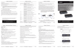
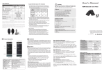
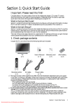
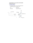
Specifications
Video Resolution (max.)
Extension Distance
Connection
Power Supply
Weight (g)
H x W x D (mm)
DVI Model
Input
Output
Top Panel LEDs
(Power/ Connection) Status
IR Control Jack
Audio Jack (Speaker+ MIC)
Video Resolution (max.)
Extension Distance
Connection
Power Supply
Weight (g)
H x W x D (mm)
Dual Color x 1
Considerations on Duplex Multi-Mode Optical Fiber
Installation
IR Transceiver x 1
IR Receiver x 1
Full HD (1920 x 1080)
WUXGA (1920 x 1200)
1000M (1080p)
800M (1080p)
S-M / M-M Fiber Optics
M-M Fiber Optics
DC 9~12V, 1.5A
440
445
25 x 96 x 130 (each Unit)
Local Unit
Remote Unit
Single-Mode (S-M)
Multi-Mode (M-M)
DVI x 1
N/A
Single-Mode (S-M)
Multi-Mode (M-M)
N/A
DVI x 1
Dual Color x 1
Dual Color x 1
Cable Diameter (micron)
50/125μM
62.5/125μM
9/125μM
Video Signal
1080p 1080i
1080p 1080i
1080p 1080i
Single-Mode
Max. Cable (S-M) model 1000
Length
Multi-Mode
(meter)
800
(M-M) model
1200
450
550
1000
1200
1200
350
450
--
--
Package Contents
2
Operation
Optional:
IR External Sensor Kit
1.8M DVI+Audio / HDMI Cable
Product Description
L1
The LEDs on the Extender Units show the real-time status indicating
the linking and communication between the Local Unit and Remote
Unit. Users can identify the present status through the LED indicator on
the top.
The quality of the output signal will depend largely upon the quality
of video source, cable and display device used. Low quality cables
degrade output signal causing elevated noise levels. Please use the
proper cable and make sure the display device is capable of handling
the resolution and refresh rate selected.
N/A
N/A
1
Yes
1
1
N/A
Yes
Local Unit
DVI
(S-M)/(M-M) Remote Unit
1
N/A
N/A
1
Yes
N/A
1
1
N/A
Yes
Local Unit
1
N/A
N/A
1
Yes
Remote Unit
N/A
1
1
N/A
Yes
Local Unit
HDMI
(S-M)/(M-M) Remote Unit
1
N/A
N/A
1
Yes
N/A
1
1
N/A
Yes
R1
R5
F
pt
rO
ibe
ic s
,
ode, 800
lti - M
Mu
s@
Meter
IR Transceiver
HDCP Video Source
Remote Unit
1920 x 1080 @ 1,000M
1920 x 1200 @ 1,000M
IR Receiver
Use high quality
Video Cable for the
best output signal.
Remote Unit
R8 R7 R6
(For DVI Model ONLY)
Connect to the DVI/ HDMI source
Connect to the DVI/ HDMI monitor
Use Multi-mode optical fiber for the extender
L2 R2 SC-SC Fiber Interface
connection
L3 R3 Reset Button
Video signal reset button
L4 R4 Power Supply
Apply the proper power to the unit
Green: Power On
L5 R5 LED Indicator
Blue: Connect to a powered-on extender unit
Plug the external sensor
L6 R6 IR Control Jack
(L6:Transceiver / R6:Receiver) here
L7 R7 Audio Jack
MIC jack (for DVI model only)
L8 R8 Audio Jack
Speaker jack (for DVI model only)
R1
1920 x 1080 @ 800M
1920 x 1200 @ 800M
RoHS
R2 R3 R4
NOTE: The system will disable the video output signal when it detects
non-HDCP compliant display(s) on playing the HDCP video source. All
the connected output displays MUST be HDCP compliant, when the
video source is HDCP compliant.
L1
1920 x 1080 @ 1,000M
1920 x 1200 @ 1,000M
PP5-MVP822Z-0Z1
Remote Unit
DVI, Multi-Mode (M-M)
(For DVI Model ONLY)
1920 x 1080 @ 800M
1920 x 1200 @ 800M
◘ The final specification is the actual product based.
◘ Features and functions may be added or changed
after the manual was written. Please visit our
website to download the latest version of manual
for reference.
IR Remote Controller
HDCP compliant
Max. Resolution
Extension Distance
Connection Patterns
L2 L3 L4
L8 L7 L6
(optional)
1
N/A
HDMI
(M-M)
x 1 set
L5
IR Receiver
x1
x1
x1
Local Unit
Remote Unit
DVI
(M-M)
1. HDCP compliant monitors with HDMI interface for the HDCP video
source
2. DVI/ HDMI cable
Local Unit
IR Transceiver
x1
x1
x2
System Requirements
Installation
Users can connect the video source to the Local Unit, connect the
monitor to the Local Unit and/or Remote Unit, and use a SC to SC
duplex multi-mode fiber optics cable for the SC-SC fiber port connection
between the Local and Remote Unit. After all device connections are
completed, connect the provided power cord into an appropriate power
source and plug the opposite end into the power connector on the Unit
to power up.
Input
Output
Audio
DVI
DVI
Fiber
Fiber
HDMI
HDMI
Model
Extender Local Unit
Extender Remote Unit
Power Adapter Set
Power Adapter with necessary AC Cord
or
Plug-in Power Adapter
User’s Manual
Multi-mode SC-SC duplex Fiber Optic Cable (for test)
Foot Pad Set
2.Users may need to order appropriate cable lengths conforming to the
application environment; however, the maximum cable length should
not exceed certain meters (refer to the table above); otherwise, the
signal degradation may occur especially for video resolution.
3.Do not exceed the cable bend radius. Fiber optic cable can be broken
when kinked or bent too tightly, especially during pulling.
4.Do not twist the cable. Twisting the cable can stress the fibers.
Tension on the cable and pulling ropes can cause twisting.
5.Don’t look into the ends of any fiber optic cables. Exposure to invisible
laser radiation may result.
6.Follow the cable manufacturer's recommendations. Fiber optic cable
is often custom designed for the installation and the manufacturer
may have specific instructions on its installation.
IR Transceiver x 1
IR Receiver x 1
Input x 1 set
Output x 1 set
Full HD (1920 x 1080)
WUXGA (1920 x 1200)
1000M (1080p)
800M (1080p)
S-M / M-M Fiber Optics
M-M Fiber Optics
DC 9~12V, 1.5A
490
500
25 x 96 x 130 (each Unit)
Before Installation
● Determine where the Local and Remote Unit will be located
● Use SC to SC duplex Multimode fiber optics cable (50/125 or
62.5/125) for the interconnection between Local and Remote Unit
● Make sure that the Fiber cable length is long enough for the
connection between the Local Unit and the Remote Unit to prevent
having to splice fiber. Try to complete the installation in one pull.
● The Extender is HDCP compliant and required to use the HDCPcompliant display when it is connecting to the HDCP video source.
● Never attempt to disassemble or reassemble the enclosure for any
purpose. This may cause personal injury and/or property damage.
● HDTV compatible
● Extend the single-link DVI (HDMI) signal up to 800 meters
@ 1080p far away via fiber optics multi-mode technology
● Support stereo audio (DVI model)
● IR extention available
● Fully compliant with HDMI 1.3b specification (HDMI model)
● HDCP compliant and Blu-ray ready
● Completely free of Electromagnetic Interference (EMI)
Single-Mode
(S-M)
Multi-Mode (M-M)
VIDEO Extender
Features
1.The OM3 multi-mode untwisted-pair fiber optics cable (50/125 and
62.5/125) terminated with SC duplex connectors is recommended to
use for the interconnection between Local Unit and Remote Unit. The
table below shows the specifications.
Cable Type
Caution
Do not stare into beam or view directly into the ends of any
fiber optic cables. Exposure to invisible laser radiation may
result. The laser beam can cause injury to the eye.
D
1
Dual Color x 1
!
● Prior to the installation, ensure to power off all devices that will be
connected to this system.
● Place cables away from fluorescent lights, air conditioners, and
machines that are likely to generate electrical noise
ul
lH
Input
Output
Top Panel LEDs
(Power/ Connection) Status
IR Control Jack
Remote Unit
Single-Mode (S-M)
Multi-Mode (M-M)
N/A
HDMI x 1
Video Cable
Max. 1.8M
HDMI Model
Local Unit
Single-Mode (S-M)
Multi-Mode (M-M)
HDMI x 1
N/A
User's Manual
Video Connector
Local Unit
DVI, Multi-Mode (M-M)
HDMI model does not include Audio port.
(HDMI is a compact audio/ video interface)
F