1
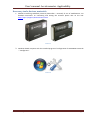
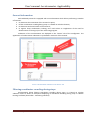
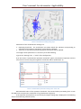
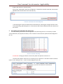
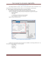
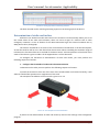
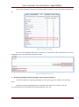
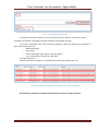
User’s manual. Accelerometer. Applicability. Contents Necessary tools, devices, materials .............................................................................................................. 2 General information ...................................................................................................................................... 3 Filtering coordinates crowding during stops................................................................................................. 3 Determination of driving style ...................................................................................................................... 5 Determination of strike and incline .............................................................................................................. 8 Appendix №1. Accelerometer setting commands ......................................................................................12 Appendix №2. Interpretation of a field of the device status ......................................................................14 SPA “GalileoSky” LLC Page 1 User’s manual. Accelerometer. Applicability. Necessary tools, devices, materials 1. Satellite monitoring GalileoSky terminal (hereinafter – terminal) of one of modifications. For detailed instructions on connecting and setting the terminal please click on the link: http://7gis.ru/support/documentation.html. Picture 1 2. Windows-based computer with the installed program of configuration of GALILEOSKY terminals – "Configurator" Picture 2 SPA “GalileoSky” LLC Page 2 User’s manual. Accelerometer. Applicability. General information Each GalileoSky terminal is equipped with an accelerometer which allows performing a number of functions: 1. 2. 3. 4. to determine the orientation of the terminal in space; to filter coordinates crowding during stops. It is based on vehicles vibration; to determine strike and incline of the terminal; to register sharp accelerations, braking, turns and strikes on roughnesses of the road for determination of driving style in the monitoring program. Indications of the accelerometer are displayed in the “Device” tab of the Configurator. The appearance of accelerometer indications is presented in Picture 3 of this manual. Picture 3. Accelerometer indications in the “Device” tab Filtering coordinates crowding during stops Accelerometer allows filtering coordinates crowding during stops. It is based on vehicles vibration. Picture 4 shows an example of displaying of coordinates crowding during stops in «Wialon Hosting» software (hereinafter - monitoring software). SPA “GalileoSky” LLC Page 3 User’s manual. Accelerometer. Applicability. Picture 4. Coordinates crowding during stops Parameters of the accelerometer settings are: 1. Operating threshold – the acceleration size above which the vibration corresponding to operation of the engine or movement of the vehicle is defined. 2. Time after a stop of the vehicle during which coordinates will be updated. To configure these parameters it is necessary to do the following: а) go to the “Settings” tab -> “Track” of the Configurator; б) in the section "Accelerometer operation threshold" specify a threshold of operation and the time after the vehicle stops, during which coordinates will be updated (Pic. 5). Picture 5. Accelerometer parameters setting in the “Track” tab Recommended value of the operation threshold– from 40 and above proceeding from a ratio that 600 units correspond to acceleration of 1g (acceleration of gravity). If the operation threshold size is set correctly the object during stop is displayed in the following way in the monitoring software (Pic.6). SPA “GalileoSky” LLC Page 4 User’s manual. Accelerometer. Applicability. Picture 6. Filtering of coordinates crowding You can also configure the settings of sensitivity and time for filtering of coordinates crowding during stop by means of commands listed in Table 1 of the Appendix №1. Determination of driving style The terminal can detect abrupt acceleration, braking, sharp turn, and strikes on rough road. To fix the above-mentioned events and send them to the monitoring server it is necessary to perform the following steps. 1. Install the terminal and set its orientation. For correct operation of this function, the terminal should determine its orientation in space relative to the vehicle. Picture 7 shows the orientation by default. For correct operation of the accelerometer the terminal must be placed face up. Picture 7. Default orientation of the terminal If you cannot install the terminal according to Pic. 7, optional installation is acceptable with the following calibration of the orientation. To calibrate the relative orientation of the terminal to the vehicle you will need to do the following: а) set the terminal so that it had a hard link with the vehicle body; SPA “GalileoSky” LLC Page 5 User’s manual. Accelerometer. Applicability. б) place the vehicle on a level surface; в) go to the “Commands” tab of the Configurator and perform shock 0 command, the terminal will determine the direction to the earth (Pic. 8). Picture 8. “Commands” tab of the Configurator г) start driving the vehicle at speed of more than 20 km/h, choosing the straight sections of the road, accelerating and braking and in a few minutes the terminal will determine the direction of the vehicle. 2. Set sending of the data about the driving style To enable sending data about the driving style to the monitoring server it is necessary to select “Driver behaviour (only dynamic archive)” in the “Protocol” tab of the main packet of the Configurator (Pic. 9). Picture 9. “Protocol” tab setting ATTENTION! Driving style data are stored only when the dynamic archive is on. To switch the dynamic archive on it is necessary to set "dynamic" in the field “Archive structure mode” in the “Settings” tab -> “Track” of the Configurator (Pic. 10). SPA “GalileoSky” LLC Page 6 User’s manual. Accelerometer. Applicability. Picture 10. Enabling dynamic archive The settings specified in articles 1 and 2 can be made with the help of commands. List of commands and their meanings are listed in Tables 2, 3 and 4 of Appendix 1 of this manual. 3. Check availability of data about driving style in monitoring software. To check the data about driving style in monitoring software, follow these steps: а) go to the “Messages” tab, specify the object and parameters to generate the report: Monitoring object; Time range; In “Message type” field choose “Data messages”; In the “Parameters” field specify “Raw data”; б) press “Execute” button (Pic. 11); Picture 11. “Messages” tab of monitoring software в) make sure that the data from the terminal are available in monitoring software (Pic. 12). Driving style data are displayed in the following fields: course_accel; braking_accel; turn_accel; vertical_accel. SPA “GalileoSky” LLC Page 7 User’s manual. Accelerometer. Applicability. Picture 12. Driving style data in monitoring software The data received can be used for generating reports on the driving style of the drivers. Determination of strike and incline All devices can determine strike and incline of the terminal. This functionality allows you to set the critical values of the strike and inclination, which can serve as signs of a vehicle crash or other emergency situations. In case of fixation of the above-mentioned signs the terminal indicates this by SMS, phone call or photograph. The strike is considered as an excess of the set threshold of acceleration in the horizontal plane, at that the tenth bit will be set in the field of the device status. When exceeding the maximum angle of inclination the first bit will be set in the field of the device status. Full interpretation of the fields of the status of the device is given in Table 5 of the Appendix No. 2 of this document. To configure the functional of determination of strike and incline, you must perform the following sequence of actions: 1. Configure the thresholds of strike and incline determination To determine the strike you must perform the following sequence of actions: а) install the terminal so that one of the axes of the accelerometer was located vertically, it will allow to exclude false operations on roughnesses of the road. The example of installation of the terminal is given in Pic. 13. Picture 13. The example of terminal installation. b) switch on the determination of strike and incline by means of the settings in the Configurator program. SPA “GalileoSky” LLC Page 8 User’s manual. Accelerometer. Applicability. For this in the “Settings” tab -> “Signaling settings” in the section “Shock and roll detection” set an operating mode and the minimal shock acceleration (Pic. 14). Picture 14. Determination of strike and incline setting in the “Signaling” tab c) set the maximum incline angle and permissible time of exceeding of this angle in the Configurator in the “Settings” tab -> “Signaling settings” in the section “Shock and roll detection” (Pic. 14). 2. Set strike and (or) incline alarm actuation To set the alarm system for strikes and inclinations of the terminal it is necessary to execute the following sequence of actions: а) start the Configurator and go to the “Settings” tab -> “Signaling settings” b) in the section « Shock and roll detection in signaling mode» choose «Mode» (for example, “roll enables alarm”), choose the type of notification and, if necessary, enter the text message (Pic. 15). Picture 15. Setting of parameters of the signaling on strike and incline c) adjust alarm duration in the field "Max time in alarm" (Pic. 16). Picture 16. Alarm duration setting. d) press “Apply” button. SPA “GalileoSky” LLC Page 9 User’s manual. Accelerometer. Applicability. e) go to the “Protocol” tab and tick the field “Status of device” in the main packet settings (Pic. 17) Picture 17. Protocol tab setting f) turn on the signaling mode with the help of «S» command in the “Commands” tab of the Configurator (Pic. 18) or send this command in SMS. Picture 18. Enabling of alarm mode. 3. Check the availability of alarm messages in the monitoring software To check the delivery of signaling messages to the monitoring server, perform the following steps: а) make sure that the signaling mode is activated in the terminal. To do this, send the “ST”command in the "Commands" tab of the Configurator (Pic. 19) SPA “GalileoSky” LLC Page 10 User’s manual. Accelerometer. Applicability. Picture 19. Checking the signaling mode. b) simulate a situation in which one of critical values of strike and (or) an inclination will be exceeded, for example, to provide a terminal inclination angle higher than 20°; c) go to the “Messages” tab in the monitoring software, specify the object and parameters to generate the report (Pic. 11): Monitoring object; Time range; In field “Messages type” choose “Data messages”; In the “Parameters” field specify “Raw data”; Press Execute button. d) make sure alarm messages are received by the monitoring software (Pic. 20). Picture 20. Checking the display of alarm messages in the monitoring software Accelerometer parameters setting is completed; the terminal is ready to operate. SPA “GalileoSky” LLC Page 11 User’s manual. Accelerometer. Applicability. Appendix №1. Accelerometer setting commands Table 1. Accelerometer threshold setting commands Command format Parameters Explanation Example AccSens Sens,TO Sens – accelerometer sensitivity; TO – the time after the vehicle stops, during which coordinates will be updated, [sec]. This function allows you to avoid unnecessary outliers after the vehicle stops. Default value is = 40,300. Sens value equal to 600 is 1g (g –gravitational acceleration) Request: AccSens 40,300 Reply: Accelerometer sensitive: sens = 40,time out=300 Table 2. Command to determine the orientation of the terminal, determination of strike and incline Command format Parameters Shock Mode,Angle,Timeout,ShockSens Mode – strike determination mode: 0 – strike determination is switched off; 1 – strike determination is switched on, X axis is in vertical position; 2 – strike determination is switched on, Y axis is in vertical position; 3 – strike determination is switched on, Z axis is in vertical position. Angle – maximum incline angle [0º-180º], value equal to 180 switches incline determination off; Timeout – maximum allowable time when incline angle exceeded, [sec.] ShockSens – maximum acceleration at exceed of which a strike is detected. 600 points – gravitational acceleration. Explanation Enabling strike and incline determination mode. Example Request: Shock 3,30,5 Reply: Shock: Mode=3,MaxAngle=30,RT=5; Table 3. Internal archive structure changing command Command format Parameters FLASHARCHIVE Dynamic,SendOrder Dynamic – whether the dynamic archive structure is off or on: 0 – the dynamic archive structure is off, all possible data are saved in archive; 1 – the dynamic archive structure is on, only the data selected to be transmitted to the server are saved in archive. SendOrder – order of data transmission from the archive to the server: 0 – the data are sent deep into the archives, the most actual data are sent first, SPA “GalileoSky” LLC Page 12 User’s manual. Accelerometer. Applicability. then the oldest ones; 1 – the data are sent in chronological order. Explanation Example Archive structure setting and the setting of the data transmission order to the server Request: FLASHARCHIVE 1,1 Reply: FLASHARCHIVE:Dynamic=1,StraightSendOrder=1; Table 4. Command enabling driving style data sending Command format Parameters Explanation MainPackBit index,value index – tag number, which will be on or off for transmission to the server; value – 1, if this tag should be transmitted to the server, 0, if this tag should not be transmitted to the server Main packet configuring. Example of Request: MAINPACKBIT 174,1 enabling driving Reply: MainPack2 = 1000000000000000000000000000000000000000000000b style data sending SPA “GalileoSky” LLC Page 13 User’s manual. Accelerometer. Applicability. Appendix №2. Interpretation of a field of the device status Table 5. Interpretation of a field of the device status Bit number Field explanation 0 0 – vibration level corresponds to parking; 1 – to driving (set by AccSens command). 1 0 – incline angle does not exceed the allowable one; 1 – incline level exceeds the allowable one. 2 0 – None of the trusted iButton keys are connected; 1 – one of the recorded to the SD-card iButton keys is connected. 3 0 – there is a SIM card; 1 – GSM modem can’t determine the SIM-card. 4 0 – terminal is outside the Geofence; 1 – terminal is inside the Geofence. 5 0 – voltage of internal source is normal; 1 – lower than 3.7 V. 6 0 – GPS antenna is connected; 1 – disconnected. 7 0 – voltage of internal terminal bus supply is normal; 1 – declined from normal. 8 0 – external supply voltage is normal; 1 – declined from normal (set by powincfg command). 9 0 – vehicle is stopped; 1 – vehicle is started (set by mhours command). 10 0 – vibration level corresponds to the normal movement, 1 – vibration level corresponds to a strike. 11 0 – GPS operates; 1 – GLONASS unit operates. 12 13 Signal quality, range: [0-3]. The less value, the worse communication. 14 0 – signaling mode is off; 1 – on. 15 0 – no alarm; 1 – alarm activated. SPA “GalileoSky” LLC Page 14