1
SC1602MBM—16x2 Characters MODBUS RTU Master LCD
User’s Manual
MODBUS
Slave
Device
R
S
4
8
5
/
2
3
2
Modbus Data
Modbus Query
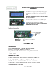
SC1602MBM is a Master Modbus LCD that is programmable to read and display data from any Modbus Slave
device.
It reads up to 4 Bytes data from register 3xxxx or 4xxxx.
•
•
•
•
•
•
•
•
•
RS485 or RS232 communication option
Programmable baud rate and parity bit.
Max. display value : 999,999
Programmable data types : 16 bits Unsigned Integer, 16 bits Signed Integer, 4 Digits BCD, 6 Digits BCD or
32 bits Unsigned Integer.
Programmable polling time 0.1 s to 25.5 s
Response timeout : 50ms
Programmable fixed decimal point ( d.ddddd , dd.dddd, ddd.ddd, dddd.dd or ddddd.d )
Programmable fixed display text
Configuration method: MODBUSMasterLCD software.
Fixed Display Text
Data field
The Data Field and Text Display Area
The data field is the area on the LCD where the received data will be displayed. It can be configured to anywhere
on the 16x2 LCD. The width of the data field is also programmable.
Fixed text area is the text that is permanently displayed after power up. It is programmable.
Display Option
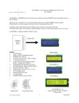
SC1602MBM-YG
www.siliconcraft.net
SC1602MBM-LC-YG
(Double Character Size)
SC1602MBM-B
1
14 June 2010
SC1602MBM—16x2 Characters MODBUS RTU Master LCD
User’s Manual
Connecting the LCD
Configuration Jumper—J4
Transistor Output Header , J5
5V
GND
RS485 Port
LCD Contrast
Adjust
J2
SC1602MBM-YG / B Back
RS485 Port
RS232
Header
TXD ( TTL )
RXD( TTL )
TXD ( RS232 )
RXD ( RS232 )
GND
5V
Configuration Jumper, J4
GND
5V
Transistor
Output
Header, J5
TXD( RS232 )
RXD( RS232 )
GND
LCD Contrast Adjust
SC1602MBM-LC-YG Back View
www.siliconcraft.net
2
14 June 2010
SC1602MBM—16x2 Characters MODBUS RTU Master LCD
User’s Manual
Configure the LCD
Download and install MODBUSMasterLCD software from our website at www.siliconcraft.net/download.htm
Select the correct COM port and module. ( SC1602MBM )
Close J4 jumper and power on the LCD. It should displays “**SETTING MODE**” on the first line.
Click on the “Connect button” and then the “Configure LCD” button to bring up the configuration window.
Configure the LCD to transmit the modbus
command.
[ Slave ID ] [ Function Code ] [ Start Register
Address Hi ] [ Start Register Address Lo ]
[ No. of Points Hi ] [ No. of Point Lo ] [ CRC
Hi ] [ CRC Lo ]
Polling interval is the frequency of which the
command will be transmitted by the LCD.
Data Display Start Location is location on the
LCD screen where the most significant digit
of the received data will be displayed.
0 is the top left corner
31 is the bottom right corner
www.siliconcraft.net
3
14 June 2010
SC1602MBM—16x2 Characters MODBUS RTU Master LCD
User’s Manual
At the text input area , key in the text to be displayed. ^^^^^^ is the data field
area.
Example :
^^^^^^ will be 6 digits wide display area
^^^^.^ will be 5 digits wide with one decimal place
After you had keyed in all the parameters, click on “Send Config Data” .
If the data is received correctly by the LCD, it will display “**SETTING DONE**”.
If there is error during transmission, it will displays “**SETTING ERROR**”.
When the configuration is done properly, power down the LCD and remove jumper J4.
MODBUS Command
[ Slave Address ] [ Function Code ] [ Start Address Hi ] [ Start Address Lo ] [ No of Points Hi ] [ No of Points Lo ]
[ CRC Hi ] [ CRC Lo ]
Above is the structure of the MODBUS command transmitted by the LCD every x X 100ms.
Supported function code is 03 and o4 only.
No of points is either 1 or 2 depending on how you want the LCD to interpret the received
data.
Supported data types are:
Unsigned integer : 2 Bytes ( No of Points = 1 )
Signed integer : 2 Bytes ( No of Points = 1 )
4 Digits BCD : 2 Bytes ( No of Points = 1 )
6 Digits BCD : 4 Bytes ( No of Points = 2 )
Long Integer : 4 Bytes ( No of Points = 2 )
0 to 65535
- 32768 to 32767
0 to 9999
0 to 999999
0 to 999999
Note that maximum display value is 999999. If the data received is more than 999999 the
LCD will display “ —————- “ on the data field.
Alarm Trip Point
This value control the transistor output on J5 pin header. If the data received is greater
than Alarm trip point value, the transistor will be turned on.
The transistor output schematic diagram and connection to a LED example.
Max sink current : 200mA
www.siliconcraft.net
4
14 June 2010
SC1602MBM—16x2 Characters MODBUS RTU Master LCD
User’s Manual
Configuration Example
LCD will transmit this MODBUS command every 1 second ( 10 x 100 ms ) with 9600, 8N1 data
0x01 , 0x04 , 0x00, 0x00 , 0x00, 0x02 , [ CRC Hi ] [ CRC Lo ]
If the response from the Slave Device address 1 is
0x01, 0x04 , 0x04 , 0x00 , 0x01, 0x03, 0x23 , [ CRC Hi ] [ CRC Lo ]
The received data is 0x00010323 ( Hex ) or 66339 ( Decimal )
The LCD display will be like :
www.siliconcraft.net
5
14 June 2010
SC1602MBM—16x2 Characters MODBUS RTU Master LCD
User’s Manual
Mechanical Dimension ( millimeter )
Standard Size Version
Large Characters Version
www.siliconcraft.net
6
14 June 2010
SC1602MBM—16x2 Characters MODBUS RTU Master LCD
User’s Manual
Specification
Power Supply: min 4.5VDC max 5.5VDC ( 5.0VDC nominal )
Current Consumption: 100mA typical ( Standard Size Version )
250mA typical ( Large Character Version )
Operating Temperature: 0ºC to 50ºC
Connection: Screw terminals accept 12 to 26 AWG
Non Volatile Memory Write Cycle: Min 100,000
Non Volatile Memory Data Retention: Min 100 years
Output Maximum sink current: 200mA
LCD
View Angle: 6 o’clock
Characters: 16 x 2
View Area: 64.5mm x 13.8mm ( Standard Size Version )
99 mm x 24 mm ( Large Character Version )
Backlight: Yellow Green or Blue LED
Available Accessories ( Sold Separately )
Aluminum Front Panel Mounting Plate
www.siliconcraft.net
RS232 cable , DB9 Female to P1 Header
7
14 June 2010