1
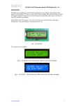
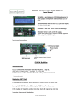
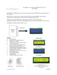
SC2004A—20x4 Characters Serial LCD Display User’s Manual
SC2004A is an intelligence LCD module design to ease
project development that requires a LCD display.
Its RS232 interface board receives and interpret serial data
and output the data to the LCD display accordingly.
SC2004A works with any host controller with serial UART
port.
SC2004A replaces older version SC2004.
Fig 1. SC2004A-YG
Display Option Available
1.
SC2004A Features
•
RS232 or serial TTL interface
•
Controllable LED backlight brightness
•
85 Bytes UART receive buffer eliminates
delay requirement between commands
•
Bar graph drawing commands
•
20 messages storage for easy retrieval, each
20 characters wide.
•
Large Numbers Display Function
•
8 GPIOs individually configurable as input or
output.
•
4x4 Keypad Interface
•
2 Analog Inputs ( 0 to 5V range )
•
8 User’s Define Characters
•
Programmable baud rate 9600/19200 bps
•
9 to 12VDC Power Supply
2.
3.
SC2004A-YG Dark Characters on Yellow Green
LED backlight
SC2004A-B White Characters on Blue LED
backlight
SC2004A-W Dark Characters on White LED
backlight
Fig 2. SC2004A-B
Fig 3. SC2004A-W
Fig 4. Optional Aluminum Panel Mounting Plate
1
www.siliconcraft.net
4/27/2010
SC2004A—20x4 Characters Serial LCD Display User’s Manual
Connecting SC2004A
IO8 ( Column 4 )
IO7 ( Column 3)
IO6 ( Column 2 )
IO5 ( Column 1 )
IO4 ( Row 4 )
IO3 ( Row 3 )
IO2 ( Row 2 )
IO1 ( Row 1 )
COM
P2
Fig 5. GPIO / Keypad Connector
Fig 4: SC2004A Back View
Not Used
Not Used
TXD ( TTL )
RXD ( TTL )
TXD ( RS232 )
RXD ( RS232 )
COM
P1
Fig 7. Mating Connector for P1/P2 ( Molex C-Grid 0.1” )
Fig 8. Connection to RS232 DB9 Connector
Fig 6. Communication Port
Fig. 9 Optional Accessories: RS232 Cable
Communication
Communication with SC2004 is through its UART serial port either RS232 or TTL interface.
8 data bits, no parity , 1 stop bit ( 8,N,1 )
Baud rate is programmable to 9600* bps or 19200 bps.
* Factory default
Displaying texts
SC2004A displays whatever characters it receives from the serial port, starting from the top left corner. Supported
internal characters is listed in Table 1.
2
www.siliconcraft.net
4/27/2010
SC2004A—20x4 Characters Serial LCD Display User’s Manual
Table 1. Supported Characters
Control Characters
0x08
Backspace
0x0B
Cursor Home
0x0C
Next Line
0x0D
Clear Screen
0x0E
Cursor Left
0x0F
Cursor Right
Move cursor one position left and delete the character
Send cursor to top left corner , LCD screen unchanged.
Move cursor to the beginning of the next line.
Clear LCD screen and send cursor home.
Move cursor one position to the left.
Move cursor one position to the right.
Text Display Example
To display
LCD Demonstration
4÷2=2
Send : “LCD Demonstration” , 0x0C, 0x34,0x20 , 0xFD, 0x20, 0x32, 0x3D,0x32
Total : 25 Bytes
3
www.siliconcraft.net
4/27/2010
SC2004A—20x4 Characters Serial LCD Display User’s Manual
User’s Defined Characters
Apart from the character set listed in Figure 11, 8 memory spaces are reserved for user’s defined characters.
Each custom character is 5 x 8 pixels matrix represented by 8 bytes of data.
Figure 10: Example of a Custom Character
Custom character above is represented by
0x04, 0x06, 0x07, 0x04, 0x04, 0x04, 0x04, 0x1F
Custom characters can be defined by sending command
0xFE , 0x64, [ 8 Bytes x 8 Bytes Custom Characters Bitmap ]
Before these custom characters can be displayed, it must be loaded to the LCD memory.
This is done by command 0xFE,0x08.
Send 0x00 through 0x07 to display custom character 0 to 7 respectively.
Note : Graph drawing command shares the same bitmap memory with custom characters on the LCD. Thus, both
cannot be used simultaneously.
Cursor Control
Cursor is the indicator of the current position on the
LCD where the character is to be displayed. By default, the cursor is hidden. To turn it on send command
0xFE,0x01 for underline type cursor or 0xFE,0x02
for block blinking type of cursor
To hide it , send command 0xFE,0x03
Figure 11. Row and Column Positions
Cursor can be moved to any position on the screen by command
0xFE,0x32,[row number],[column number]
Example: to move cursor to row 2, column 10
0xFE,0x32,0x02,0x0A
Delete row
Texts on any row can be cleared by command 0xFE,0x2D,[row number]
Cursor is moved to the beginning of the selected row after execution of this command
Delete column
Texts on any row can be cleared by command 0xFE,0x2E,[column number]
Cursor is moved to the next column at row 3 after execution of this command
4
www.siliconcraft.net
4/27/2010
SC2004A—20x4 Characters Serial LCD Display User’s Manual
LED Backlight Control
The backlight is turn on by command 0xFE,0x06 and turn off by command 0xFE,0x07
Brightness is control with command 0xFE,0x28, [ Brightness level ]
Where brightness level = 50 min, 250 max
Backlight is turn on when the module is powered up.
Texts Messages Storage
20 memory locations is reserved for storage of commonly used messages. Each is 20 characters wide.
Messages can be programmed by user with the command
0xFE, [memory location address] , [ 20 bytes texts including spaces]
Where memory location address is 0xC8 ( 200 Decimal ) for location 0 and 0xDB ( 219 Decimal ) for location 19
respectively.
Messages is retrieved and displayed with command
0xFE,0x34,[ row number where text to be displayed] , [ memory location address 0 to 19 ]
Big Numbers
SC2004 is capable of drawing 4 big numbers each spanning 4 rows by 4 columns.
Initialize big numbers command must be issued before this command can be used. 0xFE , 0x08
Draw big numbers command is 0xFE, 0x63 , [ 4 digits ASCII numbers ].
Supported numbers are 0 to 9 and space ( 0x20 )
To draw numbers “ 2004 “ on the screen. First clear the LCD.
Initialized big number. [ 0xFE,0x08 ].
Send 0xFE,0x63 , 0x32 , 0x30, 0x30 , 0x34
Figure 12 : Draw Big Numbers Example
Analog Ports
0-5VDC
AN 1
0-5VDC
AN 2
Fig 13. Analog Ports Inputs
COM
Analog 1 & 2 measure voltage of 0 to 5V.
Read Analog 1
Command: 0xFE, 0x0B
Response:
0xFA, [ADC Value MSB], [ADC Value LSB]
Read Analog 2
Command: 0xFE, 0x0C
Response:
0xFB, [ADC Value MSB], [ADC Value LSB]
ADC value is 1024 if input is 5V
5
www.siliconcraft.net
4/27/2010
SC2004A—20x4 Characters Serial LCD Display User’s Manual
Bar Graph
Graph can be drawn from left to right or right to left. The
starting point of the graph is the current cursor position.
Initialize horizontal graph command ( 0xFE,0x04 ) must be
issued before this command can be used.
In the example in Figure 15, the starting point of the graph is
at column 10.
Figure 13: Horizontal Bar Graph
To draw the graph at row 0, first set the cursor to row 0, column 10. Then issue the draw left to right graph command
0xFE , 0x2B , [ length of the graph, in this case 26 )
The maximum length of the graph depends on the starting position of the graph. In the example above, maximum
length is 50.
If a new graph is drawn over the existing graph, the existing graph will not be automatically override. This is OK if
the new graph length is greater than the existing one. However, if the new graph is shorter in length, the graph must
be erase first before a new graph is drawn.
Ensure that cursor position is set to the beginning of the graph first.
Figure 14: Vertical Bar Graph
Vertical bar graph can be drawn in any column with row 3 as
bottom of the graph. Maximum height is 32
Before the vertical graph command can be used, initialize
vertical graph command must be issued ( 0xFE, 0x05 )
Vertical graph is draw by command
0xFE,0x33, [column number], [height]
Unlike horizontal graph, drawing a new graph over the existing one will automatically erase the existing graph first.
Note : Custom Characters, Horizontal graph , Vertical Graph and Big Numbers shares the same characters set.
Thus, only one of them can be used at any one time.
6
www.siliconcraft.net
4/27/2010
SC2004A—20x4 Characters Serial LCD Display User’s Manual
GPIO on P2
IO Mode.
Each pin can be configured as input or output .
When configured as input, internal pull up resistor is activated.
When configured as output, each IO is capable of sinking or sourcing 20 mA of current at 5V
Configure GPIO command
0xFE , 0x32 . [ GPIO Direction ]
Each bit in “GPIO Direction “ set the direction of
the GPIO, where “1” set to output and ‘0” set to
input.
To control GPIOs set as output use command
0xFE, 0x2F , [ output ]
“1” to set , “0” to clear . Bit on GPIO set as inputwill be ignored.
LCD will send
0xFC, 0x00 , [ input ]
Fig 15. Tact Switch Connection Example IO 1 configured as input
Fig 16. LED Connection
Example IO 3 configured
as output
when the input is activated.
( Switch pressed )
Keypad Mode
To set P2 header as keypad input, send command
0xFE, 0x30 , 0xFE
Keypress
Response Code
1
2
3
A
4
5
6
B
7
8
9
C
*
0
#
D
0xFC, 0xFE, 0xFF
0xFC, 0xEF, 0xFF
0xFC, 0xFF, 0xFE
0xFC, 0xFF, 0xEF
0xFC, 0xFD, 0xFF
0xFC, 0xDF, 0xFF
0xFC, 0xFF, 0xFD
0xFC, 0xFF, 0xDF
0xFC, 0xFB, 0xFF
0xFC, 0xBF, 0xFF
0xFC, 0xFF, 0xFB
0xFC, 0xFF, 0xBF
0xFC, 0xF7, 0xFF
0xFC, 0x7F, 0xFF
0xFC, 0xFF, 0xF7
0xFC, 0xFF, 0x7F
7
Fig 17. Keypad Connection to P2
IO8 ( Column 4 )
IO7 ( Column 3)
IO6 ( Column 2 )
IO5 ( Column 1 )
IO4 ( Row 4 )
IO3 ( Row 3 )
IO2 ( Row 2 )
IO1 ( Row 1 )
COM
P2
www.siliconcraft.net
4/27/2010
SC2004A—20x4 Characters Serial LCD Display User’s Manual
Saving the user’s settings onto non-volatile Flash Memory
User’s setting :
•
Backlight brightness level
•
Custom Characters
•
Texts Messages
•
P2 Headers Functions
•
Baud rate
Can be made permanent so that its retains the user’s setting even after the module is powered down.
To do this , send the save settings command after you have entered all your settings.
0xFE, 0x20
When settings is saved, the module response with 0xFE, 0x20,0x20 indicating successful save operation.
Changing the Baud Rate
9600 bps
command
0xFE, 0x1E
19200 bps
command
0xFE, 0x1F
Send save settings command. Baud rate will only be changed on the next power up cycle.
SC2004App Software
This software runs on Windows PC designed to test and configure SC2004.
Available for free from www.siliconcraft.net/download.htm
You can use it to create the custom characters, define the stored texts messages and test all the functionality of
SC2004.
Hexadecimal code of all command sent to the LCD will be displayed along with all the responded code from the
LCD.
Figure 18: Communication Monitor from SC2004App Software
Electrical Specification
Power Supply:
Current consumption :
SC2004A-YG
SC2004A-B/W
Operating Temperature :
Storage Temperature:
9 to 12VDC
25mA ( Backlight Off )
Backlight Off
Max 300mA , Min 150mA
Max 50mA , Min 30mA
0ºC to 50ºC
-10ºC to 60ºC
LCD Data:
Viewing Direction:
Character size:
Dot Size:
Dot pitch:
6 o’clock
2.95 x 4.75 mm
0.55 x 0.55 mm
0.60 x 0.60 mm
8
Communication Interface : RS232 / TTL
Maximum input voltage at TTL input : 5.5V
Output High Voltage Level :
5V
Maximum sink/source current at output pin :
20mA
www.siliconcraft.net
4/27/2010
SC2004A—20x4 Characters Serial LCD Display User’s Manual
Command Summary
9
Command
Code ( Hexadecimal )
Code ( Decimal )
Cursor Home
0x0B
11
Move cursor to the beginning of the next
row
0x0C
12
Clear LCD
0x0D
13
Cursor On ( Underline )
0xFE , 0x01
254, 1
Cursor On ( Blinking )
0xFE, 0x02
254, 2
Cursor Off
0xFE, 0x03
254, 3
Initialize horizontal graph
0xFE, 0x04
254, 4
Initialize vertical graph
0xFE, 0x05
254 , 5
Backlight On
0xFE, 0x06
254, 6
Backlight Off
0xFE, 0x07
254, 7
Initialize Custom Characters
0xFE, 0x08
254, 8
Initialize Big Numbers
0xFE, 0x09
254, 9
Read Analog 1 Value
0xFE, 0x0A
254, 10
Read Analog 2 Value
0xFE, 0x0B
254, 11
Set baud rate to 9600 bps
0xFE, 0x1E
254, 30
Set baud rate to 19200 bps
0xFE, 0x1F
254, 31
Save settings
0xFE, 0x20
254, 32
Set Backlight Brightness
0xFE, 0x28 , [ Level ]
254, 40 , [ Level ]
Draw horizontal graph ( left to right )
0xFE, 0x2B , [ length ]
254, 43, [ length ]
Draw horizontal graph ( right to left )
0xFE, 0x2C , [length ]
254, 44 , [length ]
Clear selected row
0xFE, 0x2D, [ row number ]
254, 45, [ row number ]
Clear selected column
0xFE, 0x2E, [column number ]
254, 46, [ column number ]
Set outputs
0xFE, 0x2F, [ output value ]
254, 47, [ output value ]
Set P2 as GPIO
0xFE, 0x30, 0xFF
254, 48, 255
Set P2 as Keypad Inputs
0xFE, 0x30, 0xFE
254,48, 254
Set cursor position
0xFE, 0x32, [ row number ], [ column
number]
254, 50, [ row number ] , [ column number ]
www.siliconcraft.net
4/27/2010
SC2004A—20x4 Characters Serial LCD Display User’s Manual
Command
Code (Hexadecimal)
Code (Decimal)
Draw Vertical Graph
0xFE, 0x33, [ column number] , [height]
254, 51, [column number] , [ height ]
Print stored texts on selected row
0xFE, 0x34, [ row number ] , [ memory
location ]
254, 52 , [row number] , [ memory location ]
Print big numbers
0xFE, 0x63, [ 4 bytes ASCII numbers ]
254, 99, [ 4 bytes ASCII numbers ]
Define Custom Characters
0xFE, 0x64, [ 64 Bytes Bitmap Data ]
254, 100, [ 64 Bytes ASCII Bitmap Data ]
Defines texts messages
0xFE, [ memory location ] , [ 20 Bytes text 254, [ memory location ] , [ 20 bytes text
message ]
message ]
Figure: 19: Mechanical Dimension ( units in mm )
10
Maximum height : 27 mm
www.siliconcraft.net
4/27/2010
SC2004A—20x4 Characters Serial LCD Display User’s Manual
Figure 20 : Mounting Kit dimension ( units in mm )
11
www.siliconcraft.net
Thickness : 1.5 mm
4/27/2010