1
PROTOCOL
PD408 & PD216
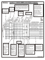
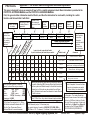
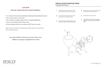
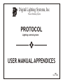
In order to keep a count
of circuits within the
system, enter an item #
in order from 1 upwards.
PD804
{
Here enter any
other circuit
reference number
there may be.
Indicate here if the
load is dimmable
or not, Y for yes, N
for no.
200
A1
Y
500
A1
Y
650
A1
A120
Y
950
A1
A205
Y
1500
B1
A101
2
3
A110
A112
4
5
0 1
0 2
6
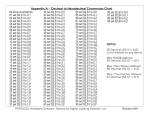
Every set of four circuits has an address, starting
from 1 to 63 which must be set on each dimmer pack.
The system recognizes a hexadecimal expression of
these numbers. Appendix A has a conversion chart
for these numbers.
Y
1
{
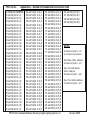
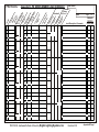
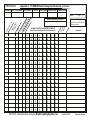
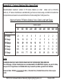
Appendix B - PD SERIES DIMMER LOAD SCHEDULE Explanation
A250
1
2
X
X
Y
1800
B1
Enter total wattage for
the circuit here.
2
5
1
1
Incandescant downlights Dining Room
1
2
Fluorescant Cove Hallway
2
1
Incandescant Chandelier hallway
2
2
Incandescant Landscape Floodlights
1
5
Incandescant Swimming Pool Lights
1
6
Low Voltage Track Dining Room
1
2
In these columns, the primary
control station and switch
control each load should be
entered. This will normally be
the main station that controls
this load by Dimmer, On, Off,
Raise, Lower, Toggle or
Momentary. Every load must
have at least one switch to
perform one or more of these
functions on it.
A
B
Enter Feed Panel
Number here.
The decimal number
of the box is entered
here ( 1 to 63). The
PD804, whilst in one
enclosure is
considered as two
boxes, each with
four ouputs which
are addressed
differently.
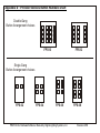
The PD216 utilizes
outputs 1 and 4 in
each box, 2 and 3
shall remain blank.
PD408 utlizes 1, 2, 3
& 4. PD804 uses 1,
2, 3 & 4 from the
first box and 1, 2, 3
& 4 from the second
box.
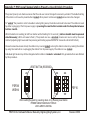
Each PD Unit requires
maximum 2 x 20 amp
breaker feeds on the
same phase. PD216
uses one feed for each
of two outputs. PD408
uses one feed for each
two of four outputs.
PD804 uses one feed
for each four of eight
outputs.
Each PD series Dimmer pack takes
2 x 20 amp feeds to provide power
for the outputs and the internal
logic of the unit.
These two feeds must be on the
same phase in order for the logic to
work correctly. Failure in doing this
will cause the system to cease
operation in a normal manner.
In this column, details
about the load should be
enetered, sych as the
type of load, its location
and a brief description.
Appendix B Page 2