1
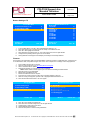
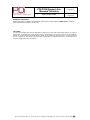
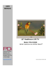
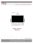
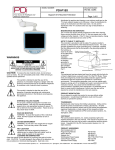
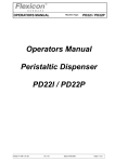
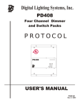
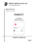
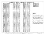
MODEL NUMBER: Document Number: PDI-P19W Support Arm Mounted Television Better Solutions Are Within ReachTM PD196-205R1 Quick Start Guide Page 1 of 8 PRODUCT ACCESSORIES (Not Included with TV) Programming Remote Patient Remote Patient Remote Support Arm ¼” to 6-Pin Jumper Cable ¼” to ¼” Jumper Cable WARNINGS CAUTION: To reduce the risk of electric shock do not remove cover (or back). No user serviceable parts inside. Refer servicing to qualified service personnel. This symbol is intended to alert the user of the presence of uninsulated ‘dangerous voltage’ within the product’s enclosure that may be of sufficient magnitude to constitute a risk of electric shock to persons. This symbol is intended to alert the user of the presence of important operating and maintenance (servicing) instructions in the literature accompanying the appliance. OVERHEAD FALLING HAZARD TV can pose a striking hazard when mounted at an elevated position. Use only PDI mounting brackets, support arms, and appropriate hardware to assure TV will not fall from the mounted position. Failure to do so may cause injury or death. RAIN AND MOISTURE WARNING: To avoid the hazards of fire or electrical shock, DO NOT expose this television to rain or moisture. OXYGEN ENVIRONMENT WARNING: Do not use in any oxygen tent or oxygen chamber. Such use may cause a fire hazard. WET LOCATION Apparatus shall not be exposed to dripping or splashing and no objects filled with liquids, such as vases, shall be placed on the apparatus. PD108-420 PD108-427 (Remote w/ DVD Module) PDI108-421 (Remote w/o DVD Module) PDI-1000 Series PD106-416 PD106-417 NOTE TO CABLE TV INSTALLER This reminder is provided to call the cable TV systems installer’s attention to Article 820-40 of the National Electrical Code. The code provides guidelines for proper grounding and, in particular, specifies that the cable ground shall be connected to the grounding system of the building, as close to the point of the cable entry as practical. Canadian installations shall be properly grounded in accordance with the Canadian Electrical Code, Part 1. MAINTENANCE AND SERVICING The TV does not require periodic maintenance other than cleaning. Never remove the back cover of the TV; this can expose you to high voltage and other hazards. If the TV does not operate properly, unplug it and call an authorized service center or PDI. CLEANING AND DISINFECTION Clean the exterior of this television by removing dust with a lint-free cloth. CAUTION: To avoid damage to the surface of the television, do not use abrasive or chemical cleaning agents. Spot test a new disinfectant by applying test cleaning a non-obvious small spot on the TV’s back cabinet, keypad, and LCD panel. Allow the disinfectant to soak per its instructions and then wipe clean. Do not use the disinfectant if the TV’s surfaces show any sign of discoloration or softening. PRODUCT MODIFICATION Do not attempt to modify this product in any way without written authorization. Unauthorized modification could void the user’s authority to operate this product. TRADEMARKS Manufactured under license from Dolby Laboratories. Dolby and the double-D symbol are trademarks of Dolby Laboratories. All other brand names and product names used in this manual are trademarks, registered trademarks, or trade names of their respective holder. PDi and Better Solutions Are Within Reach are registered trademarks of PDi Communication Systems, Inc., Springboro, Ohio. COPYRIGHT PDI Communication Systems, Inc. claims proprietary right to the material disclosed in this user manual. This manual is issued for user information only and may not be used to manufacture anything shown herein. Copyright 2012 by PDI Communication Systems, Inc. All rights reserved. PDi Communication Systems, Inc. 40 Greenwood Lane Springboro, Ohio 45066 USA PH 937-743-6010 FX 937-743-5664 MODEL NUMBER: Document Number: PDI-P19W Support Arm Mounted Television Better Solutions Are Within ReachTM Quick Start Guide PD196-205R1 Page 2 of 8 Important Safety Instructions PLEASE READ AND KEEP THESE INSTRUCTIONS. OBSERVE ALL WARNINGS AND FOLLOW ALL INSTRUCTIONS CONTAINED IN THESE SAFETY INSTRUCTIONS AND THOSE ON YOUR TV. RETAIN THESE INSTRUCTIONS FOR FUTURE USE. Electrical energy can perform many useful functions. This unit has been engineered and manufactured to assure your safety. However, improper use can result in potential electrical shock or fire hazards. In order not to defeat the safe-guards incorporated on this TV, observe the following basic rules for its installation, use and servicing. Your TV is fully transistorized and does not contain any user serviceable components. Removal of the cabinet cover may expose you to dangerous voltages. Refer all servicing to qualified service personnel. 1. 2. 3. 4. 5. Read these instructions. Keep these instructions. Heed all warnings. Follow all instructions. DO NOT use this TV near water. TV SHALL NOT be exposed to dripping or splashing. No objects filled with liquids, such as vases, shall be placed on the TV. 6. Clean only with dry cloth. For further cleaning, use a soft cloth or paper towel dampened with water. 7. To avoid damage from disinfectants to the surface of the TV, test a small portion of the TV’s cabinet with any new disinfectant to verify that the disinfectant will not discolor or soften the enclosure. 8. DO NOT block any ventilation openings. Install in accordance with the manufacturer’s instructions. 9. DO NOT install near any heat source such as radiators, heat registers, stoves, or other apparatus that produce heat. 10. DO NOT expose this TV to rain or moisture. 11. DO NOT defeat the safety purpose of the polarized or grounding-type plug. A polarized plug has two blades with one wider than the other. A grounding type plug has two blades and a third grounding prong. The wide blade or the third prong is provided for your safety. If the provided plug does not fit into your outlet, consult an electrician for replacement of the obsolete outlet. 12. To prevent injury, this apparatus must be securely attached to the wall in accordance with the installation instructions. TVs can pose a striking hazard when mounted at an elevated position. Installation Precautions USE RECOMMENDED COAX. USE OF ANY OTHER CABLE NUMBER IS NOT RECOMMENDED. 13. Protect the power cord from being walked on or pinched 14. 15. 16. 17. 18. 19. particularly at plugs, convenience receptacles, and the point where it exits from the apparatus. DO NOT use in an oxygen tent or oxygen chamber. Such use may cause a fire hazard. Only use attachments/accessories specified by the manufacturer. Use only with the cart, stand, tripod, bracket or table specified by the manufacturer, or sold with the apparatus. When a cart is used, use caution when moving the cart/apparatus combination to avoid injury from tip-over. Unplug this apparatus during lightning storms or when unused for long period of time. Refer all servicing to qualified service personnel. Servicing is required when the apparatus has been damaged in any way, such as power-supply cord or plug is damaged, liquid has been spilled or objects have fallen into the apparatus, the apparatus has been exposed to rain or moisture, does not operate normally, or has been dropped. DO NOT attempt to modify this product in any way without written authorization. Unauthorized modification could void the user’s authority to operate this product. 1. Any changes or modifications in construction of this television, which are not expressly approved by the party responsible for compliance, could void the user’s authority to operate the equipment. 2. Use only a power source from a CSA Certified / UL Approved Class 2 Power Supply suitable for use in a Health Care Facility. This TV will operate on either DC or AC voltage, range 18 to 32 volts. 3. THIS INSTALLATION SHOULD BE MADE BY A QUALIFIED SERVICE PERSON AND SHOULD CONFORM TO ALL LOCAL CODES. READ AND FOLLOW THE SAFETY INSTRUCTIONS BEFORE ATTEMPTING THIS INSTALLATION. 4. NOTE TO CATV INSTALLER: This reminder is provided to call the CATV system installer’s attention to Article 820-40 of the NEC that provides guidelines for proper grounding and, in particular, specifies that the cable ground shall be connected to the grounding system of the building, as close to the point of cable entry as practical. 5. COAX CABLE SPECIFICATION: Coax cable selection is critical when the TV is powered from a central power supply. Due to long coax cable runs encountered in hospital installations, coax cable employing a solid copper center conductor and copper shield is required. Cable run lengths MUST NOT exceed 150 feet. Required coaxial cable numbers include Alpha 9804C (non-plenum), Belden 9248 (non-Plenum), West Penn 806 (non-Plenum), or West Penn 25806 (Plenum), which have been tested with coax-powered televisions. 6. CLEANING: Clean the exterior of this television by removing dust with a lint-free cloth. For further cleaning, use a soft cloth or paper towel dampened with water. CAUTION: To avoid damage to the surface of the television, do not use abrasive or chemical cleaning agents. 7. DISINFECTING: Do not immerse this TV, rather clean with a soft damp cloth. To avoid damage to the surface of the television, test a small portion of the TV’s cabinet with any new disinfectant to verify that the disinfectant will not discolor or soften the enclosure. 8. WARNING: To avoid the hazards of fire or electrical shock, DO NOT expose this television to rain or moisture. 9. WARNING OXYGEN ENVIRONMENT: Do not use in any oxygen tent or oxygen chamber. Such use may cause a fire hazard. PDi Communication Systems, Inc. 40 Greenwood Lane Springboro, Ohio 45066 USA PH 937-743-6010 FX 937-743-5664 MODEL NUMBER: PDI-P19W Support Arm Mounted Television Better Solutions Are Within ReachTM Quick Start Guide Document Number: PD196-205R1 Page 3 of 8 Installation for 1000 Series Support Arm Safety steps: 1) Always wear safety glasses/goggles to prevent injury from debris. 2) Follow the installation/removal instructions for your existing products. TOOL LIST: 1) P1 or P2, Phillips screw driver 2) Pliers 3) Safety glasses/goggles PARTS LIST for KIT: 1) (3) PD216-001 End Caps 2) (2) PD216-002 Base Covers 3) (2) PD216-003 Elbow Covers 4) (1) PD216-004L Left Base Cover 5) (1) PD216-004R Right Base Cover 6) (2) PD242-248 Nose Cover Spacers 7) (1) PDIPPTL61950 Plastite Screw 8) (8) PD209-004 Painted Cover Screws NOTE: 1) Attach arm to wall bracket and mount TV to arm before beginning cover installation. 2) Arm Safety Brake Pin must be removed from arm nose to install the new Nose Arm Cover. 3) DO NOT DISCARD SAFETY BRAKE PIN. Keep the safety pin for future service of the arm and/or TV. STEP 1. Snap the (3) PD216-001 End Caps into the ends of the arm sections as pictured. There should be 2 in the front section and 1 in the back section. STEP 2. Attach the Base Cover halves using (2) PD209-004 screws. STEP 3. Securely snap the Elbow Covers around the elbow joint. Hook over the top edges of the elbow plates then snap the lower hooks along the bottom edges. When the halves are properly installed there should only be a thin seam visible where the halves meet. STEP 4. Attach the left and right Nose covers to the nose using (4) PD209-004 screws and (2) PD242-248 nose cover spacers as pictured. Loosely fasten the nose cover spacers into the hex bosses of one of the nose covers using (2) PD209004 screws. Slide the PD242-248 spacers thru the hex holes in the sides of the nose. Attach the remaining nose cover to the spacers with the remaining PD209-004. Tighten the (4) PD209-004 screws to secure the nose covers. Now install the PDIPPTL61950 Plastite screw into the nose cover to secure the "bell" around the top of the LCD TV housing. When the halves are properly installed there should only be a thin seam visible where the halves meet. STEP 5. Rotate the TV and move the arm thru its range of travel to check for any inference issues. PDi Communication Systems, Inc. 40 Greenwood Lane Springboro, Ohio 45066 USA PH 937-743-6010 FX 937-743-5664 MODEL NUMBER: Document Number: PDI-P19W Support Arm Mounted Television Better Solutions Are Within ReachTM PD196-205R1 Quick Start Guide Page 4 of 8 PROGRAMMING NOTE: A programming remote control is required to perform all setup operations for the television. The programming remote (Part Number: PD108-420) is NOT packaged with the TV and must be ordered separately. The following instructions assume you have a programming remote, have correctly mounted the TV, and connected a coax cable that provides both Power and RF signal. Channel Setup The TV offers three different programmable channel banks or Service Levels: Free, Basic, and Premium. Only one Service Level is usable at a time. Setup Mode ■ ■ ■ ■ ■ ■ ■ ■ Service Level Picture Sound Channel Setup Features OSD Language Source Setup FM RADIO Setup Position: ▲▼ Exit: SETUP Channel Setup Free ► ► ► ► English ► ► Next: ◄► ■ ■ ■ ■ ■ ■ ■ ■ ■ ■ Signal Auto Program Add/Delete Channels Clear Service Level Copy Service Level Parental Control Power on Channel Channel Lock Channel Memory Override ProIdiom Position: ▲▼ Exit: SETUP Cable STD ► ► ► ► ► ► Disabled Enabled MTI Port Next: ◄► Four different tuning types are available depending upon the healthcare facilities’ signal style. Selection of the correct signal type is required for the TV to recognize all possible channels and before any channel programming can begin. 1. 2. 3. 4. Press the SETUP button to display the SETUP MODE menu. Press the CH▲ / CH▼ button to select CHANNELS. Press VOL◄ or VOL► to activate the menu item. In the CHANNELS menu, press the CH▲ / CH▼ button to select Signal. Press VOL◄ / VOL► to select Air, Cable STD, Cable IRC or Cable HRC. NOTE: Most hospitals use the Cable STD signal style. Auto Program The TV automatically scans each available channel for activity. Channels that display activity are memorized into the selected Service Level. Channel Setup ■ ■ ■ ■ ■ ■ ■ ■ ■ ■ Signal Auto Program Add/Delete Channels Clear Service Level Copy Service Level Parental Control Power on Channel Channel Lock Channel Memory Override Pro:Idiom Position: ▲▼ Exit: SETUP 1. 2. 3. 4. Auto Program Cable STD ► ► ► ► ► ► Disabled Enabled MTI Port Next: ◄► ■ ■ ■ ■ ■ ■ Mode Channel Sequence Additional Digital Signal Free Basic Premium Position: ▲▼ Exit: SETUP Analog Only Interleave A+D None Programmed ► Blank ► Blank ► Next: ◄► Enter the Channel Setup menu. Press ▲ or ▼ to highlight Auto Program. Press ► to select Auto Program. On Mode, press ◄ or ► to set the scope of channel scanning. Analog Only: TV searches for analog channels only. Digital Only: TV searched for digital channels only. Analog and Digital: TV searches for both analog and digital channels. When you choose “Analog Only”, “Additional Digital Signal” is disabled. When you choose “Digital Only” or “Analog and Digital”, then “Additional Digital Signal” is enabled. “Additonal Digital Signal” allows you to scan for additional digital signals on an alternate signal source. Press ▼to highlight Additional Digital Signal and press ► to select either None, Air, Cable Standard, Cable IRC or Cable HRC. PDi Communication Systems, Inc. 40 Greenwood Lane Springboro, Ohio 45066 USA PH 937-743-6010 FX 937-743-5664 MODEL NUMBER: Document Number: PDI-P19W Support Arm Mounted Television Better Solutions Are Within ReachTM Quick Start Guide PD196-205R1 Page 5 of 8 Press ▲ or ▼ to highlight Channel Sequence. Press ◄ or ► to set the Channel Sequence in which the channels are displayed. Interleave A+D: In the order of channel number regardless of the system. All A then D: Digital channels are displayed after all analog channels. 7. Press ▲ or ▼ to highlight the Service Level (Free, Basic, or Premium) you wish to program. The menu displays the current programming status of each level as either Programmed or Blank. NOTE: A programmed service level also can be reprogrammed if desired. 8. Press ► to start auto programming. 9. A confirmation menu will appear before proceeding. Press ▲ to start auto programming. Press ▼ to cancel the operation. The TV now will search all available channels. Auto programming requires several minutes to complete. NOTE: Digital channel auto programming may take longer than 10 minutes to complete. 10. Press SETUP to return to normal TV viewing. 5. 6. SOUND PROGRAMMING The TV’s internal speakers can be disabled requiring the use of a headphone for private listening. commonly used in dialysis clinics and multiple occupancy rooms. This option is Internal Speaker Enable The speaker’s inside the TV’s cabinet can be enabled (turned ON) or Disabled (turned OFF). Sound ■ Balance ■ Minimum Volume ■ Maximum Volume ■ Power on Volume ■ Internal Speaker Enable ■ HDMI 1 Audio Port ■ HDMI 2 Audio Port ■ Composite/S-Video Sound Mode Position: ▲▼ Exit: SETUP 1. 2. 3. 4. 5. Internal Speaker Enabled 0 25 100 Last ► HDMI HDMI 1 L+R 2 Next: ◄► ■ ■ ■ ■ ■ ■ ■ ■ ■ ■ TV Composite Video S-Video Component HDMI 1 HDMI 2 PC-ANALOG FM RADIO Slot 1 Slot 2 Position: ▲▼ Exit: SETUP Enabled Enabled Enabled Enabled Enabled Enabled Enabled Enabled Enabled Disabled Next: ◄► In the SOUND menu, press CH▲ / CH▼ button to select the Internal Speaker Enable menu item. Press VOL◄ / VOL► to activate the menu item. Press the CH▲ / CH▼ button to select the desired Service Level(s) or Sources. Press VOL◄ / VOL► to alternately select Disabled or Enabled to turn OFF or ON the TV’s internal speakers. Press the SETUP button to return to the preceding menu. PDi Communication Systems, Inc. 40 Greenwood Lane Springboro, Ohio 45066 USA PH 937-743-6010 FX 937-743-5664 MODEL NUMBER: Document Number: PDI-P19W Support Arm Mounted Television Better Solutions Are Within ReachTM PD196-205R1 Quick Start Guide Page 6 of 8 Cloning Cloning allows quick programming of a TV from a USB thumb drive. The cloning operation involves first downloading setup information from a programmed host TV to a USB thumb drive and then uploading the setup information to another TV. Cloning also can be used to re-program a programmed TV. Save Settings to USB Cloning Port 1. 2. Turn on the TV. Insert a blank USB thumb drive into the cloning port in the back of the TV. Using the Programming Remote, press SETUP to open the Setup menu. 3. 4. Press the ▲ or ▼ to select Cloning. Press ►to open the Cloning Menu. Setup Mode ■ ■ ■ ■ ■ ■ ■ ■ ■ Service Level Picture Sound Channel Setup Features OSD Language Source Setup FM RADIO Setup Cloning Position: ▲▼ Exit: SETUP 5. 6. 7. Cloning Free ► ► ► ► English ► ► ► Next: ◄► The TV requires 15 seconds to perform the Clone operation. Wait for the Clone menu to reappear. Exit: SETUP Press Channel Up (Yes) to continue. Screen will go black and Red LCD light will flash. LCD light will stop flashing and turn green. TV will reboot and Cloning Main Menu will appear. Press ► to highlight the Save Settings to USB Disk. Cloning Main Menu ■ Download Firmware To TV ■ Save Settings to USB Disk ■ Restore Setting to TV Position: ▲▼ Exit: SETUP 8. 9. 10. 11. Insert USB Flash Drive into TV Cloning Port. Press Channel Up(Yes) to Continue. ► ► ► Next: ◄► Save Settings To USB Model P19W ■ P19LCDC ■ P19W ■ P22LCDC_P ■ P32LCDE ■ P26LCDE ■ P15X ■ CV2200M ■ CV2600M ■ CV3200M ■ CV3700M Position: ▲▼ Exit: SETUP Press ▲ or ▼ to highlight P19W in menu. Press ►to save the settings to the USB drive. The screen will go black, red LCD light will flash. LCD light will stop flashing and turn green and TV will reboot. Cloning Main Menu will reappear and will display the message “Successfully Saved”. PDi Communication Systems, Inc. 40 Greenwood Lane Springboro, Ohio 45066 USA PH 937-743-6010 FX 937-743-5664 ► ► ► ► ► ► ► ► ► ► Next: ◄ ► MODEL NUMBER: Document Number: PDI-P19W Support Arm Mounted Television Better Solutions Are Within ReachTM Quick Start Guide PD196-205R1 Page 7 of 8 Restore Setting to TV Cloning Main Menu ■ Download Firmware To TV ■ Save Settings to USB ■ Restore Setting to TV Disk Position: ▲▼ Exit: SETUP 1. 2. 3. 4. 5. 6. Restore Settings To TV Model P19W ■ P19LCDC ■ P19W ■ P22LCDC_P ■ P32LCDE ■ P26LCDE ■ P15X ■ CV2200M ■ CV2600M ■ CV3200M ■ CV3700M ► ► ► Position: ▲▼ Exit: SETUP Next: ◄► ► ► ► ► ► ► ► ► ► ► Next: ◄► In Cloning Main Menu, press ▲ or ▼ to highlight Restore Settings to TV. Press ► to display a list of previously stored TV setups on the USB thumb drive. Press ▲ or ▼ to highlight the P19W file. Press ►to restore the settings to the TV. The screen will go black, red LCD light will flash. LCD light will stop flashing and turn green and TV will reboot. Cloning Main Menu will reappear and will display the message “Successfully Restored”. Firmware The firmware for the model PDI-P19W TV is field upgradeable. A data file is written to a USB flash drive, connected to the TV’s USB interface cable, and updated using the TV’s menus. Once complete, the TV settings must be reprogrammed. 1. 2. 3. 4. Insert a USB thumb drive into a computer. Open your web browser and go to http://www.pdiarm.com/support/. Click on Firmware& Driver Updates. Download the firmware you need and save it to your desktop. NOTE: Please contact technical support if you have issues downloading the latest firmware. 5. Open the zip file you just downloaded. 6. Extract files to the USB thumb drive. 7. Remove the USB drive from the computer. 8. Insert it into the cloning port of the P19W. (See connections diagram on page 6.) 9. When the cloning menu appears, press ▲ or ▼ to highlight Download Firmware to TV. 10. Press ► and Download Firmware to TV menu appear. Download Firmware to TV Cloning Main Menu ■ Restore Settings to TV ■ Save Settings to USB ► ► ■ Upgrade All ■ Upgrade Main FW to M ■ Download Firmware to TV ► ■ Upgrade I/O to K ■ Upgrade Wireless Audio to W ■ Custom Upgrade Position: ▲▼ 11. 12. 13. 14. 15. Next: ► Back: ◄ ► Position: ▲▼ Press ▲ or ▼ to highlight the Upgrade All. Press ► to select it. Screen will go black, red LCD light will flash. LCD light will turn green and TV will reboot. Cloning Main Menu will reappear. Press the Setup button to exit the Cloning Main Menu. PDi Communication Systems, Inc. 40 Greenwood Lane Springboro, Ohio 45066 USA PH 937-743-6010 FX 937-743-5664 ► N e x t : ► MODEL NUMBER: PDI-P19W Support Arm Mounted Television Better Solutions Are Within ReachTM Quick Start Guide Document Number: PD196-205R1 Page 8 of 8 Additional Information Additional information is available in the user manual. Please visit the company web site at pditv.com or contact PDI. Please request document number: PD196-172R1. DISCLAIMER The author and publisher have used their best efforts in preparing this manual. PDI Communication Systems, Inc. make no representation or warranties with respect to the accuracy or completeness of the contents of this manual and specifically disclaim any implied warranties or merchantability or fitness for any particular purpose and shall in no event be liable for any loss of profit or any other damages. The information contained herein is believed accurate, but is not warranted, and is subject to change without notice or obligation. PDi Communication Systems, Inc. 40 Greenwood Lane Springboro, Ohio 45066 USA PH 937-743-6010 FX 937-743-5664