1
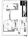
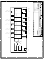
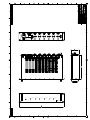
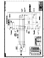
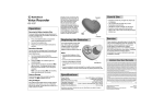
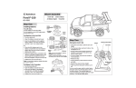
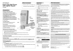
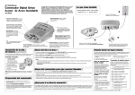
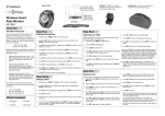
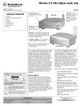
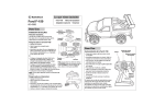
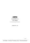
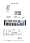
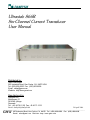
Ultrastab 866R
Six-Channel Current Transducer
User Manual
Distributed by:
GMW Associates
955 Industrial Road, San Carlos, CA 94070 USA
Tel: (650) 802-8292 Fax: (650) 802-8298
Email: [email protected]
Website: http:/www.gmw/com
Manufactured by:
Danfysik A/S
Mollehaven 31
DK 4040 Jyllinge
Denmark
Tel: +45 46 76 81 50 Fax: 45 46 73 15 51
Email: [email protected]
24 April 2006
____________________________________________________________________________
GMW
955 Industrial Road, San Carlos, CA 94070 Tel: (650) 802-8292 Fax: (650) 802-8298
Email: [email protected] Web site: http://www.gmw.com
TABLE OF CONTENTS
PAGE
1. INTRODUCTION AND SPECIFICATIONS.
1.1
1.1.1
1.2
Introduction. ................................................................................................................. 2
Working principle. ........................................................................................................ 3
Warranty........................................................................................................................ 4
2. RECEIVING AND UNPACKING.
2.1
2.2
Receiving the goods. ..................................................................................................... 5
Instructions for unpacking. ........................................................................................... 5
3. INSTALLATIONS.
3.1
3.2
Installation..................................................................................................................... 6
Interlock circuit. ............................................................................................................ 6
4. OPERATING INSTRUCTIONS.
4.1
Switching ON and Operating Instructions. ................................................................... 7
5. THEORY OF OPERATION.
5.1
5.2
5.3
General description of the Electronics .......................................................................... 8
Current transducer 866 & 867....................................................................................... 8
Programming of the output voltage............................................................................... 9
6. MAINTENANCE. ................................................................................................................. 9
APPENDIX A - SALES REPRESENTATIVE AND SERVICE ........................................... 10
APPENDIX B – VOLTAGE OUTPUT MODULES ............................................................ 11
APPENDIX C – SPECIFICATIONS 866R- 09A03 ............................................................ 14
APPENDIX D – DRAWINGS 88729B & 88201G & 89111................................................ 15
APPENDIX E – DRAWINGS 21908-0001-OA, 866R Outline................................................
APPENDIX – DRAWINGS 13908-0000-OA, 866R Schematic.............................................
DANFYSIK A/S - DK-4040 JYLLINGE - DENMARK
DOC.NO. 12A03
2
1.1 INTRODUCTION.
The ULTRASTAB 866R system is based on the very proven 866-600 precision current
transducer technology. In this new configuration, named Model 866R, we have packaged the
modules into a 3 to 6 channel system with a measuring capacity of up to 600A DC or 425A AC
(RMS). The system can be used either as a stand-alone system or as a current range extender on
high performance Power Analysers.
The system is delivered as a complete system, including auxiliary power supply, mounted in a
19” rack mount cabinet, transducer heads type 866-600 or 867-400 or a combinations of both
types and connecting cables.
The basic version is equipped with 3 channels, but can be extended up to totally 6 channels.
The 866R system has a standard analog output of +/- 1V and an analog current output that is
depending on the chosen type of transducer, and the selected maximum primary current, when
the instrument was ordered, please refer to chapter 5.3.
Front view of the Ultrastab 866R with LED status information for the individual channels.
Rear view of the Ultrastab 866R with connectors for the individual Transducers/ channels and
25 pole female D-sub socket for interlock connections. The grounding option is located in the left
side of the cabinet.
DANFYSIK A/S - DK-4040 JYLLINGE - DENMARK
DOC.NO. 12A03
3
1.1.1 Working principle.
The DANFYSIK ULTRASTAB 866R Current Transducer system is a unique design, based on
the zero-flux principle for galvanic isolated precision current measurement.
With the primary current conductor through the transducer head center hole and current flowing,
the electronics will generate a current in the built-in compensation winding, counter-balancing
the primary ampere-turns.
A very sensitive and extremely low noise detector circuit will detect when zero-flux is obtained,
and an analog 0 – max. ±400mA or 0 - ±1V signal will be generated at the output terminals in
direct proportion to the primary current.
The front panels of the modules are equipped with LED’s giving you the information:
-
Power
Normal operation
Transducer connected
DANFYSIK A/S - DK-4040 JYLLINGE - DENMARK
DOC.NO. 12A03
4
1.2
Warranty
DANFYSIK A/S warrants the equipment delivered from the company to be free from any
defects in materials and workmanship for a period of:
12 Months from the date of installation or max. 18 months from the date of shipment.
Whichever is shortest.
Within this warranty period DANFYSIK A/S will repair or replace any defective parts free
of charge either on the customers site or at our factory at our choice.
DANFYSIK A/S will pay or reimburse the lowest two-way freight charges on any items
returned to DANFYSIK A/S or our designated agent/representative provided DANFYSIK
A/S has given prior written authorisation for such return.
This warranty shall not apply to any equipment which our inspection shows to our
satisfaction, to have become defective or unworkable due to mishandling, improper
maintenance, incorrect use, or any other circumstances, not generally acceptable for
equipment of a similar type.
DANFYSIK A/S reserves the right on standard products to make changes in design without
incurring any obligation to modify previously manufactured units.
The foregoing is the full extent of the warranty and no other warranty is expressed or
implied. If no event Danfysik shall be liable for special damage arising from the delivery,
late delivery, or use of the equipment.
If any fault develops the following steps should be taken:
Notify DANFYSIK A/S giving full details of the problems and include Model, Type, Serial
number, and Order number.
On receipt of this information DANFYSIK A/S will send you either service information or
instructions for shipping.
All shipments of DANFYSIK A/S equipment should be made according to our instructions
and shipped in the original or a similar package.
For smaller parts a cardboard carton will be sufficient, providing the parts are wrapped in
plastic or paper and surrounded with at least 10 centimetres of shock-absorbing material.
DANFYSIK A/S - DK-4040 JYLLINGE - DENMARK
DOC.NO. 12A03
5
2. RECEIVING AND UNPACKING.
2.1. RECEIVING THE GOODS
The shipping package and the ULTRASTAB should be thoroughly inspected for signs of obvious
physical damage immediately upon receipt.
All materials in the package should be checked against the enclosed packing list and the list of
standard delivery below. DANFYSIK A/S will not be responsible for any shortages unless
notified immediately.
ULTRASTAB 866R. Standard Delivery:
- Electronics 19 inch crate
- Three Transducer heads type 866-600A or three type 867-400
- Three Connections cables 5m
- AC power cable
- Manual.
2.2. INSTRUCTIONS FOR UNPACKING
The ULTRASTAB is shipped in a cardboard carton.
If the equipment is damaged in any way, a claim should be filed with the shipping agent, and a
full report of the damage should be forwarded to Danfysik A/S or our local agent/representative
immediately upon arrival.
Upon receipt of this report, Danfysik will forward instructions concerning the repair, replacement
or return shipment.
Please include the Type No., Serial No., and Order No. for the ULTRASTAB 866R on any
communication with DANFYSIK or our representative.
DANFYSIK A/S - DK-4040 JYLLINGE - DENMARK
DOC.NO. 12A03
6
3. INSTALLATION
1. Check that the specified AC voltage and current are available and that the ambient
temperature is within the range specified in this manual.
2. Establish the Ground connection according to the local authority regulations and the
requirements of the equipment via the AC power plug.
3. Connection cables:
Mount the provided connection cables between the Electronics crate rear side sockets and the
Transducer Heads. Use channel 1 to 3 as default.
4. Concerning Output terminals on the rear side of the cabinet:
If the Voltage output shall used, the shorting clamp on the Current output must always be
mounted. The value of the internal shunt is written on a label.
If output current is used - i.e. for connecting an external shunt - the shortening clamp must
be opened.
The grounding clamp shall normally be mounted to obtain best noise performance.
5. Check that all cables terminated in plugs are pushed fully home.
6. Transducer head.
The transducer head may be installed in any orientation, but be careful to keep it away from
power transformers, and other units producing significant magnetic stray fields. Please refer
to the “busbar free zone” in the technical specifications of the 866R
If above checkpoints are fulfilled the system is ready for use.
3.2 INTERLOCK CIRCUIT
The interlock circuit is present at a 25 pole D-Sub socket at the rear side of the cabinet.
The output signal can be used in any general safety interlock set up circuit.
There is an Opto coupler output for each channel which are ON at NORMAL OPERATION.
Interlock plug:
Channel 1: pin 12 Collector & pin 11 Emitter
Channel 2: pin 10 Collector & pin 9 Emitter
Channel 3: pin 8 Collector & pin 7 Emitter
Channel 4: pin 6 Collector & pin 5 Emitter
Channel 5: pin 4 Collector & pin 3 Emitter
Channel 6: pin 2 Collector & pin 1 Emitter
DANFYSIK A/S - DK-4040 JYLLINGE - DENMARK
DOC.NO. 12A03
7
VCC
Maximum 5mA
RESISTOR
User sid e
One example of the interlock output
4. SWITCHING ON AND OPERATING INSTRUCTIONS
When the instructions for installation in pos. 3.1 have been completed, the ULTRASTAB 866R
Electronics can be switched ON.
Please note:
If two voltage output is connected to the same instrument e.g. an oscilloscope, the output will not
be valid, due to the internal shorting of the two channels GND.
Any instrument connected to the Voltage output MUST have a differential input to avoid a
grounding loop via power ground.
1. Switch ON the AC power and the green LED – Control Power will be on.
The Green LED - NORMAL OPERATION on the units connected will be "ON"
2 The total assembly is in NORMAL OPERATION, and an analogue current/voltage proportional
to the measured current will be generated by the electronics circuitry and presented at the
output terminals.
NORMAL OPERATION means: Cable connected, measured current is within 115 % of
programmed maximum current and internal aux. power supplies are working.
3. If the Green LED - NORMAL OPERATION is not "ON", please recheck that all connections
are properly made and secured by the screws.
4. If any problem should occur during this operation, please contact our local representative or
Danfysik direct.
5. All performance data refers to max. Current for the type 866-600 or 867-400 transducer head.
In order to obtain maximum accuracy of the instrument, lower currents can be measured by
applying more primary turns through the transducer head and divide the output signal with the
number of turns or program to a lower maximum current. For high sensitivity measurements
it is important to distribute the turns with even space all around on the transducer head.
6. In order to avoid excessive saturation of the iron core in the transducer head, this unit must be
switched on before the actual primary current source is applied.
DANFYSIK A/S - DK-4040 JYLLINGE - DENMARK
DOC.NO. 12A03
8
7. THEORY OF OPERATION.
5.1 GENERAL DESCRIPTION OF THE ELECTRONICS
The ULTRASTAB 866R electronic crate is equipped with a switch mode power supply delivering the
+/-15V to the transducer heads. This power supply covers the following range of mains input voltages:
85 – 264Vac / 47-63Hz .
The build in interlock and Voltage Output module( VOM ) receives the compensation current from the
transducer heads and make it possible to measure the current or the voltage on the internal precision
resistors.
5.2 ULTRASTAB 866-600 & 867-400 CURRENT TRANSDUCERS
The transducers have an arrow sticker on the side face. With the main current flowing in the direction of
the arrow, a positive voltage will be developed across an internal or external Burden resistor.
The transducers can be mounted in any orientation, and the influence from external stray fields is very
low.
Please note: The transducer contains fragile materials in the zero detector assembly, and care should be
taken in handling.
DANFYSIK A/S - DK-4040 JYLLINGE - DENMARK
DOC.NO. 12A03
9
5.3 Programming the output Voltage
The output voltage is factory programmed to match the ordered number of channels and the maximum
current to be measured.
If a need for more channels or other current values is desired, please contact Danfysik or our
representative.
For information on how to field install new Voltage Output modules, please see appendix B.
The output voltage is always +/- 1V at maximum primary current, provided that the correct primary
current has been selected when ordering. The value of the internal shunt is indicated on a label for each
channel.
The configuration of your system is labelled on the lid of the 866R unit and shown in appendix B in this
manual.
6.0 MAINTENANCE
The ULTRASTAB 866R assembly does not require any maintenance under normal operation.
Please note:
Faults within the calibrated components and the zero flux detector can only be repaired by returning
the ULTRASTAB 866R assembly to Danfysik A/S direct or via our local representative.
Failing to follow this procedure will make the warranty null and void.
DANFYSIK A/S - DK-4040 JYLLINGE - DENMARK
DOC.NO. 12A03
10
APPENDIX A. - SALES REPRESENTATIVE AND SERVICE.
DANFYSIK A/S,
Moellehaven 31,
DK-4040 Jyllinge
DENMARK.
Phone No.: +45 46 78 81 50
Fax No.:
+45 46 73 15 51
E-mail: [email protected]
WWW.danfysik.dk
DISTRIBUTORS
EUROPE:
SIGNALTEC GmbH
Dr. Carlo-Schmid-Straße 112
D-90491 Nürnberg
Germany
Telephone: +49 911 5971919
Fax: +49 911 5971920
Email: [email protected]
Web: www.signaltec.com (www.signaltec.de)
USA:
GMW ASSOCIATES,
955 Industrial Road
San Carlos
CA 94070
P.O. Box 2578
Redwood City
CA 94064
Phone No.: (650) 802-8292
Fax No.: (650) 802-8298
E-mail: [email protected]
WWW.gmw.com
INDIA:
TRANSACT INDIA CORPORATION
5/1A, Grants Building
Arthur Bunder Road
Colaba
Mumbai - 400 005
Phone No.: (22) 285 5261
Fax No.:
(22) 285 2326
E-mail: [email protected]
DANFYSIK A/S - DK-4040 JYLLINGE - DENMARKDOC.NO. 866R-12A03 Manual.doc
11
APPENDIX B: Installation of Voltage Output Modules ( VOM ):
If there is a need for adding more channels or changing the maximum current value of the
Ultrastab 866R the following should be done:
Remove the mains power cable from the unit
The lid is removed by unscrewing the two screws on the side of the cabinet.
The new VOM module can now be installed between the ribbon cable and the main circuit
board, please see photo.
Voltage
Output
module
DANFYSIK A/S - DK-4040 JYLLINGE - DENMARKDOC.NO. 866R-12A03 Manual.doc
12
List of available VOM’s:
Product
Description
Part No.
866-VOM75
Voltage Output Module
with ± 10V analog output for ± 75A
81088903
866-VOM150
Voltage Output Module
with ± 10V analog output for ± 150A
81088904
866-VOM300
Voltage Output Module
with ± 10V analog output for ± 300A
81088905
866-VOM600
Voltage Output Module
with ± 10V analog output for ± 600A
81088906
DANFYSIK A/S - DK-4040 JYLLINGE - DENMARKDOC.NO. 866R-12A03 Manual.doc
13
Programming label for ULTRASTAB 866R
Transducer type
866-600
A
Primary current
600A (425A RMS)
B
300A
(210A RMS)
200mA
C
150A
(105a RMS)
100mA
D
75A
(52A RMS)
50mA
A
867-400
Not used
Output Current
400mA
Not used
B
400A
(280A RMS)
200mA
C
200A
(140A RMS)
100mA
D
100A
(70A RMS)
50mA
DANFYSIK A/S - DK-4040 JYLLINGE - DENMARKDOC.NO. 866R-12A03 Manual.doc
ULTRASTAB 866R
3 – 6 Channel Current Transducer System
BASIC SPECIFICATION FOR A SINGLE CHANNEL
Primary current I (max.)
Polarity
Output at max. primary current:
- Current output (screw terminals)
- Voltage output (BNC)
Load capacity:
- Normal load
- Overload (basic function maintained)
- Overload (fault)
Transfer ratio accuracy:
- Current I(max) / 400mA
- Voltage I(max)/1V
Linearity:
- Current mode
- Voltage mode
Measuring / ratio stability:
Current mode:
- v.s. temperature
- v.s. time
Voltage mode:
- v.s. temperature
- v.s. time
Offset:
- Initial
- Drift v.s. temperature
- Drift v.s. time
Noise feedback to main conductor
DC – 50 kHz (RMS)
(Measured on the primary current cable – one turn)
Output noise (RMS):
DC – 10 Hz
DC – 10 kHz
DC – 50 kHz
Slew rate (10-90%)
spec866R_09A03.doc
600ADC / 425A RMS
Bipolar
± 400mA
± 1V
*)
0 – 100%
0 – 110%
500% (0.1 s)
< 2 ppm
< 0,01%
< 1 ppm
< 25 ppm
<0,3 ppm/°C
1 ppm/month
<3 ppm/°C
10 ppm/month
< 25 ppm
< 0,3 ppm/°C
< 2 ppm/month
< 10µV
< 1 ppm
< 10 ppm
< 30 ppm
≥ 10kA / ms
09A03
BASIC SPECIFICATION FOR A SINGLE CHANNEL
Channel separation at max nominal current, and slew
rate at 40kA/ms
0.05% / ÷66dB
Bandwidth (small signal 0.5%) 3 dB
DC to 100 kHz
Busbar free zone to be within linearity specification:
Cylinder shape (diameter x length)
ø 150 x 150 mm
Test voltage transducer head
5 kV AC (RMS)
Cable length electronics measuring head
5m
Operating temperature
10 – 50°C
Storage temperature
0 – 60°C
Input power requirement
Emission complying standard
Immunity complying standard
Operating humidity
85 - 260V, AC, 50/60Hz
max. 100V A
EN 50081-2
EN 50082-2-1995
20 – 80%
Mechanical dimensions:
A. Electronics
Weight
483 x 88 x 250 mm
Approx. 4 kg
B. Transducer (dwg. 88312)
Hole for conductor
Weight (each transducer)
122 x 98 x 65 mm
ø 26 mm
1 kg
All ppm figures refer to max. output.
Specifications are subject to change without notice.
*)
Optional output data:
The 866R can be delivered factory programmed for:
± 200mA / ± 1V at 300A primary current - or
± 100mA / ± 1V at 150A primary current - or
± 50mA / ± 1V at 75A primary current
DANFYSIK A/S ⋅ DK-4040 Jyllinge ⋅ Denmark ⋅ Tel.: +45 46 79 00 00 ⋅ Fax: +45 46 79 00 01
Web: www.danfysik.dk – e-mail: [email protected]
spec866R_09A03.doc
09A03
A
B
5
Power
85-250 VAC
50/60 Hz.
PSU1 -17V
Filter
4
VOM module
VOM module
Channel 2
VOM module
Channel 3
LED Normal operation
Uout +/- 1V
Transducer
LED Normal operation
Uout +/- 1V
Transducer
LED Normal operation
Uout +/- 1V
Transducer
LED Normal operation
Uout +/- 1V
VOM module
Channel 4
2
LED Normal operation
Uout +/- 1V
Transducer
MØLLEHAVEN 31
3
DK-4040 JYLLINGE
DENMARK
TELEPHONE: +45 46 79 00 00
VOM module
Channel 5
2
VOM module
Channel 6
REV. 1
SHEET.
1 OF 1
(820) 89111
DWG.NO.:
DESIGN APP.
PROD APP.
PROJ. ENGR.
DRAWN BY. JB
1
1
Created. Wednesday, September 24, 2003 10:17:53 S I ZE A4
Transducer
E-MAIL: [email protected]
09:22:39
OR DER NO. -------TELEFAX: +45 46 79 00 01
Modified. Friday, September 26, 2003
CUSTM. --------
FILE. T:\PROJEKTER-IGANG\PC STYRET TEST SYSTEM\TEST BOX\866R MAIN SCHEMATIC.DSN
SCHEMATIC
Ultrastab 866R main blockdiagram
Iout -
LED Power
Status/Interlock
LED 866 Powered
Iout +
LED 866 Powered
Iout +
Channel 1
Iout -
LED 866 Powered
Iout +
Main PCB
Iout -
LED 866 Powered
Iout +
C
Iout -
LED 866 Powered
Iout +
LED Normal operation
Uout +/- 1V
3
Iout -
LED 866 Powered
Iout +
PSU1 +15V
4
Iout -
D
5
Transducer
A
B
C
D
CONTROL
POWER
DANFYSIK
NORMAL OPERATION
NORMAL OPERATION
NORMAL OPERATION
NORMAL OPERATION
NORMAL OPERATION
NORMAL OPERATION
866 POWERED
866 POWERED
866 POWERED
866 POWERED
866 POWERED
866 POWERED
1
2
3
4
5
6
CURRENT TRANSDUCER SYSTEM
ULTRASTAB 866 R
R
SN: 100XXXXX
Programming
Transducer type Primary current Output current
A
A
B
C
D
Not in use
A
B
C
D
Not in use
±1V
A
B
C
D
Not in use
A
B
C
D
Not in use
A
B
C
D
Not in use
866-600 DCB
A
B
C
D
Not in use
ANALOG OUTPUT
ANALOG OUTPUT
ANALOG OUTPUT
ANALOG OUTPUT
ANALOG OUTPUT
±1V
±1V
±1V
±1V
±1V
B
866-400 DC
600A
300A
150A
75A
400A
200A
100A
400mA
200mA
100mA
50mA
200mA
100mA
50mA
POWER
85-250V AC/50-60Hz
WARNING!
Do not connect or disconnect
Analog output and/or
Transducer head
with power on
GND
ANALOG OUTPUT
±IOUT
±I OUT
±IOUT
±I OUT
±IOUT
±I OUT
DANFYSIK
UltraStab 866R
Part No: 81088802
Serie No:
CHASSIS
TRANSDUCER 6
TRANSDUCER 5
TRANSDUCER 4
TRANSDUCER 3
TRANSDUCER 2
TRANSDUCER 1
STATUS/INTERLOCK