1
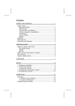
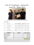
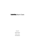
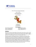
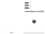
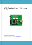
Project Final Report
Project Final Report
Z-MP3
April 23rd, 2010
James Marshall
Project Abstract
The Z-MP3 is a simple mp3 player based on the Z16 micro controller and VS1033d mp3
decoder chip. It is a prototype, developed with “breakout board” components and limited
functionality in a short period of time. It can play mp3s at a bit rate of 64kbits/s from a
SD card, pause, resume, advance to the next track, and display the file name on an LCD.
Status
Success! The Z-MP3 has achieved the base level of functionality required. It serves as
a proof of concept, and would make a suitable jumping off point to build a more robust
player.
That said, some features had to be cut due to time constraints. Mostly these are
secondary features that deal with the user interface: providing more control over the
player and displaying more useful information. For example, displaying the mp3 tag
information (such as artist and title) was not implemented, and neither was volume
control.
The core components are fully implemented as originally specified. This is partly due
to the rather vague specifications in the project proposal, and also due to the straight
forwardness of the project. For example, the mechanism for initiating transfers was never
specified, so there was not deviation from the original specification when polling the data
request pin failed to work. This wiggle room was not intentional, just a natural result of
my inexperience building these systems.
Specification
The Z-MP3 consists of 4 major hardware components: the Zilog Z16 Contest board, a
VLSI mp3 decoder chip, an SD card reader, and a LCD. All of the components besides
the Z16 where incorporated into it's own breakout board that contained supporting
components and the necessary pin outs. This greatly simplifies construction, and the only
passive components that I added were to control the contrast on the LCD.
The Z16 Contest board was by far the most complicated component, but given the
familiarity that most students have with the board and the relatively low popularity of
Zilog micro-controllers, I am not going to go into specifics about the Z16. Instead, I will
discus more generally the minimum specifications that a micro controller would need to
meet to be used in lieu of the Z16. This will also serve to give a good overview of the
system.
April 23rd, 2010
Page 1 of 8
Project Final Report
To interface with the LCD, seven GPIO pins are required. The mp3 decoder and SD
card both use SPI, so six additional pins are required (the mp3 decoder actually requires
two clock signals, one for commands and one for data). The mp3 decoder requires two
additional pins, and 3 more pins are also required for detecting button presses. This leads
us to a requirement of at least 18 GPIO pins. This may of course vary, giving platform or
component choices (for example, using a serial LCD could eliminate many pins).
The software for the Z-MP3 is rather simple, and only requires one hardware interrupt
to coordinate data transfer (more on this later) and to poll for button input. Floating point
libraries where not needed, although an implementation of the c standard libraries was
used, mostly for debugging purposes and to manipulate strings, and could thus be easily
removed.
The code itself is entirely written in c, and thus is potentially portable to other
platforms with the exception of hardware specific segments. However, given that all of
the source code only amounts to 175kB, including comments, it may be wiser to simply
rewrite the program. This has the added benefit of avoiding all of the errors in my code.
(Please keep in mind that this is un-compiled c code, so 175kB is actually much larger
than the assembly generated).
As for the computational speed of the system, requirements are again modest. The
micro controller must be able to transfer data over the SPI connects are at least 100kbits
per second to interface with the SD card. Due to possible limitations of the mp3 decoder,
only mp3s up to about 64kbit per second bit rates can be decoded, so as long as the
controller can manage over 128kbit per second rates, it should be sufficient. However, I
would recommend a more capable controller in case the designer wants to attempt to
decode faster bit rate encoded mp3s.
The issue of mp3 bit rates has to deal with the break out board containing the
VS1033d, not the actual decoder chip itself. The breakout board, produced by Sparkfun,
utilizes a 12.288 MHz oscillator to provide the VS1033d with an external clock. In the
application notes for the VS1001, VS1011, VS1002 and VS1003 chips, it is noted that
with a clock of 12.288 MHz the chip is only able to decode sample rates up to 24kHz and
bitstreams up to 96 kbit/s. This is disappointing given that mp3s typically sampled at
44.1kHz at a bit rate of at least 128 kbit/s (and all the way up to 320 kbit/s). The Z-MP3
was able to play mp3s at 22kHz and 64 kbit/s.
Another problem with the decoder's breakout board was the erratic behavior of the
DREQ pin (data request). The pin did not operate as specified, but would instead oscillate
between a high and low state. Documentation on the problem was difficult to find, but the
suspected cause is that the breakout board does not tie the chip's test bit to a high voltage,
as specified in the datasheet.
With these limitations, and the difficulties I had streaming data, the best option left
was to set an interrupt based on playing a mp3 with a 64 kbit/s bit rate and transfer data
on each interrupt. It would have been preferable to poll the DREQ pin at set intervals to
ensure that data is only sent when the buffer can handle it, but the pin was far to
unreliable. My solution is adequate, although it does produce some sound glitches as
some data is dropped when transmission speed outpaces the buffer.
April 23rd, 2010
Page 2 of 8
Project Final Report
Complaints about the board aside, the VS1033d is very easy to work with. I simply
initialize it, and begin sending mp3 data. The chip takes care of the rest, all the way to
outputting an analog signal powerful enough to drive a set of headphones. Testing can
easily be done with the provided test mode which plays sine curves. One last note about
the component: it requires a 5.0v power source (which is not mentioned in the breakout
board specs, and the chip typically only requires two 3.3 volt sources (separate digital and
analog)).
The SD card was interfaced with using a ET-MINI SD/MMC breakout board. The
component is rather simple, so even though the specification sheet is sparse, it contains
the necessary information. The most important part to pay attention to is the schematic
which show the purpose of four jumpers on the board: pull-ups for the SPI lines. This is
vital information when connecting the component to other SPI components.
The difficulty in communicating with the SD card wasn't actually the hardware, but
the software interface need to talk to the fat32 file system on the SD card itself. We will
look at this in more detail in a later section, but in short there are many fat32 libraries
available (I choose FatFS) which require you to only write the platform specific SPI
operations. The library then provides a standard c interface to the file system.
Finally, I used a Hitachi 44780 compatible LCD module: the Xiamen Amotec
ADM1602K-NSW-FBS/3.3V. This module only requires 3.3v, and has a back light (with
separate power and ground). Interfacing with the module was achieved with 11 GPIO
pins (or only 7 could be used) with a well established protocol. The 44780 standard does
have some quirks, but overall it is a simple and easy standard to work with. And the use
of ASCII values for each character code makes sending data extremely easy.
One does have to be sure to correctly set the contrast by varying the impedance on the
contrast pin. The user should be able to vary this voltage between 0.0v and 1.0v to
control the contrast. The exact amount of resistance required is a function of the amount
of voltage used to run the component, so the datasheet's suggest 10k ohms is far too much
(I believe it was written for the 5.0v version). I found that 3.3k ohms to 6.3k ohms was
sufficient: the voltage range of .85v to > 1.0v was enough that the user could make the
display clear.
That concludes the hardware for the project, so we can now discuss the software. Most
segments of code where tightly coupled to the related hardware, with the goal of
providing as clean of an interface as possible to the controlling aspects of the software.
The top level component is a simple state machine: the program is either paused,
playing music, or advancing to the next track, at which point the next track is played.
Each of these states is triggered by a button push, and the player initializes to the paused
state. Because the state transitions are triggered by button presses, the core of the
program is actually the update loop which polls the input buttons.
When the device is started, initialization routines are run, including setting a timer
interrupt to the correct interval to transfer data between the SD card and mp3 decoder.
This interrupt calls the main update routine, which may transfer data depending on state,
and occasionally polls for button presses. It is with these presses that state transitions are
initiated.
April 23rd, 2010
Page 3 of 8
Project Final Report
Bellow this simple control flow, we have supporting code to interface with the
hardware. The main components are segregated by hardware type: the timer, lcd driver,
button logic, mp3, and disk access. The only component which violates this modularity is
the SPI code, which must be accessible to both the mp3 code and the disk code.
The timer and button logic are the simplest components. The timer sets up one of the
three hardware interrupts available on the Z16 and registers an interrupt service routine.
The ISR simply calls a function pointer when it's run, so when the main program
initializes the timer, it just passes a pointer to the desired update function. The button
code's purpose is to maintain some state to prevent multiple button presses from being
registered (de-bouncing is achieved by simply checking for presses at a long interval).
The LCD code shamefully simple, and given more time would be the easiest place to
improve features quickly. It implements most of the Hitachi 44780 command interface,
and can dumbly print strings to the display. However, I would like to improve it's logic so
that it would be able to wrap or scroll text, or make use of the ability to program custom
characters (such as a play icon, or a pause icon to indicate status). Also, one could change
this code to utilize the LCD module's 4 bit mode, saving 4 GPIO pins.
Next let's look at the SPI code. This code provides hardware specific information
initializing SPI, transferring a single byte, and selecting a slave device. In selecting a
slave, the SPI code ensures that either that is the only active slave, or the function call
will fail. I found that this was invaluable when trying to debug my software; I could tell
immediately if the problem was with contention over the SPI lines.
The SD code and mp3 code both use the SPI code to communicate with their
respective hardware. The SD code was provided by the FatFS project, a small fat16 and
fat32 compatible c library for embedded devices. FatFS provides the standard c interface
to the file system (such as f_open, f_read) and only requires that the hardware specific
communication protocol is implemented. This saved me a great amount of time, as I did
not have to learn about the intricacies of the fat32 file system. In an effort to protect the
data on my SD card, the decision was made to only implement read-only functionality.
However, the c file interface itself is rather complicated, so I decided to abstract out
this details into a set of disk handling functions. The main control loop can simply call
these functions (which also maintain disk state) to open the next file, or transfer data,
without having to be cluttered with the specifics of the operations.
The mp3 code was heavily modified from a similar project I found online. It deals
with initializing, testing, and transferring data to the mp3 decoder. This code could be
much more robust, in order to provide the user with more functionality, such as volume
control or bass and treble control.
The VS1033d actually provides many features that I do not take advantage of. In fact,
it is a capable enough micro controller that it could replace the function of the Z16 board,
and drive the LCD and SD card itself. However, time did not allow me to explore this
avenue.
April 23rd, 2010
Page 4 of 8
Project Final Report
Figure 1: Hardware Schematic for Z-MP3
Figure 2: Hardware block diagram of ZMP3 showing communication interfaces.
April 23rd, 2010
Figure 3: Software block diagram showing
data and command flow (omitting initialize
routines).
Page 5 of 8
Project Final Report
Implementation & Construction
To illustrate the hardware discussed previously, please refer to Figure 1. It shows all
of the physical connections made between components. Not shown are the power and
ground lines for the mp3 decoder, SD card, which require 5.0v and 3.3v respectively.
Power is shown for the LCD, as it is connected to the passive components that control
contrast.
The choice of pins to use on the Z16 was largely arbitrary: any GPIO pins could have
been used (although using the ESPI alternate function simplified the SPI code). The pin
choices for the three smaller modules is for the most part the only available option.
Please note that the audio out jack for the mp3 decoder (represented with a speaker)
should be connected to Left, Right, and GBUF as the ground.
Figure 2 shows the conceptual layout of the hardware according to communication
interface and data flow. The SD and mp3 components both communicate via SPI, and the
thin black line shows the data path of an mp3. The mp3 component has both a data path
(input only) and a two-way command path.
The buttons and LCD are both interfaced with general purpose IO. The Z16 polls the
pins for the buttons, so communication is only one way. For the LCD, a well defined
protocol is followed, and while the majority of data flows from the Z16 to the display, the
communication can be two way.
The software is rather simple, and the previous discussion gives a sufficient overview.
Figure 3 shows the simple layout of components, omitting the buttons (simply polled by
the main routine). For details on initialization, please refer to Main's initialize function;
order is important, but this is due to implementation decisions, not fundamental
restrictions.
Physical construction was a simple matter of connecting the components using a
combination of prototyping boards and wires. From the schematic, we see that four
passive components are required, and these where laid out on the breadboard according to
the schematic. The rest of the connections where made with single wires (and yes, it did
resemble a rat's nest).
The project was assembled piece by piece as the software was developed for it. This
had the added benefit of allowing incremental testing along with the incremental
development. The components where added in the following order:
1. The LCD module. Tested by printing strings to the display.
2. The SD card. Tested by printing out a scan of all files in a directory.
3. The mp3 decoder. Tested by on board testing routines (specifying and playing
sine curves).
At this point all components where working, but only separately. The integration
phase, in which the mp3 decoder would receive data from the SD card and file
information would be printed to the LCD turned out to be a very time consuming step. It
was also at this stage that the timer and buttons where implemented, but these are trivial
April 23rd, 2010
Page 6 of 8
Project Final Report
components and did not present any problems. Testing for the integration step was simply
playing an mp3 clearly.
Retrospective
This project would not have been possible for me to do in this short of a time frame
without the use of breakout boards for the hardware components and the use of the FatFS
library. Writing a library to access a fat32 formatted disk or arranging the correct passive
components to interface with the VS1033d chip would have been projects on their own,
and far less interesting projects at that.
There are some added difficulties to using some one else libraries or components, but
the slightly higher learning curve and the hardware issues I encountered where a small
price to pay for the added convenience. And in the end, despite almost being derailed by
some of the hardware issues, I was able to put together a working mp3 player, which
given my inexperience in this field is a testament to just how helpful these breakout
boards and libraries were.
While the hardware was new to me, I do have experience writing software
applications, which aided me on the software aspect of the project. My final design is
both modular and simple, and more importantly it works. I would have liked to spend
more time on the software to increase the usefulness of the player, but honestly I doubt
that I would have learned nearly as much since once I finished the hardware and the
software interface to it, I had basically finished the most difficult parts.
And those difficult parts taught me volumes. The experience has been largely
demystifying as I learned how hardware works, and yet awe inspiring as I came to grasp
the sheer complexity of modern systems, and the fact that they still work at all.
On a more practical level, as I joked with friends, I learned how to read spec sheets.
Lots of spec sheets. I have a stack of them on my desk right now, and in just a few short
weeks they have become well worn.
That may sound tedious, and it was at times, but it also taught me how to be much
more detail oriented. A mistake about whether a pin is active low or active high can mean
an hour of debugging, so one quickly learns to pick out the important details and
remember them. This is a skill that I never had to develop working in high level
languages that give you a nice stack trace and helpful error messages when code crashes
or doesn't compile.
And speaking of languages, this project greatly increased my skills with c. The
program was by far the largest I have ever had to write in c, and I also had to learn to read
3rd party libraries with FatFS. In my final version, I actually pass a function pointer to the
timer code so that on interrupts the ISR can just make a callback, instead of having to be
tightly coupled with the main function. Earlier versions had to link to main's header file
and call specific functions that way, since I didn't know any other way to implement a
callback.
Knowing what I know now, I would have done two things differently: start earlier and
choose a different decoder chip / breakout board. The start earlier advice is pretty
April 23rd, 2010
Page 7 of 8
Project Final Report
universal for just about every class I take, so that is more of a personal goal to be less of a
procrastinator.
I was disappointed by the decoder chip and the breakout board provided by Sparkfun.
It was frustrating to be limited to such low quality mp3s, and not being able to poll the
DREQ pin forced me to use a kludge just to get the mp3s playing correctly. With a
different breakout board / decoder combination I may have been able to get the player to
a basic level of functionality quicker, at which point I would have been able to implement
more features.
Overall, I enjoyed the project and am proud of the final product. I look forward to
continuing to experiment with embedded systems.
Attachments
Following is a brief listing of attachments:
1. vs1033d.pdf – mp3 decoder specifications.
2. vs1033-v13-new.pdf – mp3 decoder breakout board schematic.
3. vs10XXan.pdf – application notes for previous VLSI mp3 decoders.
4. ADM1602K-NSW-FBS-3.3v.pdf – LCD module specifications.
5. st7066.pdf – LCD controller used by the LCD module specifications.
6. HD44780.pdf – Originally Hitachi LCD controller specifications.
7. MINISD.pdf – SD breakout board specifications.
8. UM0197.pdf – Z16 Contest Kit user manual.
9. PS0220.pdf – Z16 specifications.
In addition to the preceeding attachments, I heavily referenced the following sites:
1. http://elm-chan.org/fsw/ff/00index_e.html – The home of the FatFS libraries used
to interface with the disk.
2. http://frank.circleofcurrent.com/cache/mp3_decoder.htm – Description and code
for an alarm clock that plays mp3s. Uses the VS1033d decoder as well as the
FatFS libraries.
April 23rd, 2010
Page 8 of 8