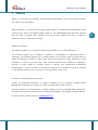
1
WIZ-iRadio User’s Manual (Ver. 1.0) ©2008 WIZnet Inc. All Rights Reserved. For more information, visit our website at www.wiznet.co.kr WIZ-iRadio User’s Manual Document History Information Revision Date Description V1.0 May 1, 2008 Original Document 2 © Copyright 2008 WIZnet Inc. All rights reserved WIZ-iRadio User’s Manual WIZnet’s Online Technical Support If you have something to ask about WIZnet Products, Write down your question on Q&A Board in WIZnet website (www.wiznet.co.kr). WIZnet Engineer will give an answer as soon as possible. 3 Technical Support: [email protected] Sales & Distribution: [email protected] For more information, visit our website at http://www.wiznet.co.kr © Copyright 2008 WIZnet Inc. All rights reserved WIZ-iRadio User’s Manual Table of Contents 1. 2. 3. 4. 5. Overview ................................................................................ 6 1.1. Evaluation Board Package ................................................... 6 1.2. Feature ............................................................................ 7 Hardware description ................................................................ 8 2.1. Board Configuration ........................................................... 8 2.2. Pin Description ................................................................ 10 2.3. Dimension ...................................................................... 12 2.4. Remote Controller ........................................................... 12 Configuration Tool .................................................................. 13 3.1. Description ..................................................................... 13 3.2. How to Use Configuration Tool - Examples ............................ 14 Firmware description .............................................................. 15 4.1. Firmware Structure .......................................................... 15 4.2. Scat File ......................................................................... 15 4.3. Compile Environment & Process......................................... 16 4.4. Firmware Operation Process .............................................. 23 4.5. Server list File ................................................................. 27 Warranty ............................................................................... 28 © Copyright 2008 WIZnet Inc. All rights reserved 4 WIZ-iRadio User’s Manual Figures Figure 1. WIZ-iRadio Board Configuration .................................................................................................8 Figure 2. JTAG Interface ......................................................................................................................................9 Figure 3. Boot Mode Selection Jumper .......................................................................................................9 Figure 4. WIZ-iRadio Modue Pin Descripation ...................................................................................... 10 Figure 5. WIZ-iRadio Module Dimension (unit : mm) ........................................................................ 12 Figure 6. WIZ-iRadio Remote Controller .................................................................................................. 12 Figure 7. WIZ-iRadio Configuration Tool.................................................................................................. 13 Figure 8. App – Scat ......................................................................................................................................... 15 Figure 9. Boot - Scat ......................................................................................................................................... 16 Figure 10. Compile - 1 ..................................................................................................................................... 17 Figure 11. Compile - 2 ..................................................................................................................................... 18 Figure 12. Compile - 3 ..................................................................................................................................... 19 Figure 13. Compile - 4 ..................................................................................................................................... 20 Figure 14. Compile - 5 ..................................................................................................................................... 21 Figure 15. Compile - 6 ..................................................................................................................................... 22 Figure 16. Firmware Operation Process .................................................................................................... 23 Figure 17. server_list.txt ................................................................................................................................... 27 Tables Table 1. WIZ-iRadio Evaluation Board ..........................................................................................................6 Table 2. Software CD Contents ........................................................................................................................6 Table 3. WIZ-iRadio Module Pin Description ......................................................................................... 11 Table 4. Firmware Structure............................................................................................................................ 15 Table 5. Read Configuration Data from EEPROM ................................................................................. 25 Table 6. IR Remote Controller Key Value .................................................................................................. 26 © Copyright 2008 WIZnet Inc. All rights reserved 5 WIZ-iRadio User’s Manual 1. Overview WIZ-iRadio receives and plays the data through Internet protocols from a streaming server. With WIZ-i-Radio, you can play all Internet braodcast without PC. 1.1. Evaluation Board Package WIZ-iRadio Evaluation Board package is composed of below items. Item WIZ-iRadio -EVB Accessory Quantity WIZ-iRadio module 1 WIZ-iRadio Base Board 1 Power Adaptor (5V/500mA) 1 Software CD 1 UTP Cable 1 Remote Controller 1 Table 1. WIZ-iRadio Evaluation Board Directory WIZ-iRadio DOCs Manual Contents WIZ-iRadio User’s Manual (Korean/English) Datasheet All sorts of datasheets Application Note How to use ShoutCast Server HW SW Schematics All sorts of schematics Part List All sorts of part lists Firmware EVB B/D Firmware PC Utility All sorts of Tool Program Table 2. Software CD Contents z Software CD contents can be different according to the version. Before use, check “ReadMe.txt”. © Copyright 2008 WIZnet Inc. All rights reserved 6 WIZ-iRadio User’s Manual 1.2. Feature 1.2.1. Hardware Feauture WIZ - iRadio z MCU : ARM7TDMI 32-bit RISC CPU(STR710FZ2T6) z RAM : 2Mbytes external RAM z ROM : 256Kbytes Flash program memory(ARM7 Internal Flash) z LAN : WIZnet W5100 Hardwired TCP/IP Embedded Ethernet Controller z CODEC : VS1033C z Power Consumption : 175mA WIZ-iRadio Base Board z Power : DC 5V input z LCD : 128 x 64 graphic LCD with Blue Backlight z JTAG I/F : 2 x 10 male box header z SERIAL I/F : 1 x 4 male 2.54mm pin header(GND, RX, TX, VCC) z IR Receiver z AUDIO Output : 3.5Ø stereo phone jack z LAN PORT : RJ45 with Transformer(1CT:1CT), 2LED 1.2.2. Software Feature Play streaming audio from Internet radio station Support Shoutcast server, HTTP, MMS Support DHCP and static IP Firmware update through network © Copyright 2008 WIZnet Inc. All rights reserved 7 WIZ-iRadio User’s Manual 2. Hardware description 2.1. Board Configuration WIZ-iRadio-EVB is composed of a main module and a base board. The main module contains the MCU, RAM, Ethernet Controller, and CODEC that are responsible for the main functions of Internet Radio. In the base board, power for module operation and peripheral devices for input and output are located. 8 Figure 1. WIZ-iRadio Board Configuration z Power Jack : DC 5v INPUT(MIN 500mA), diameter(Φ4.2/Φ1.3) z RESET S/W : Reset Switch. LCD and WIZ-iRadio module will be reset. z JTAG I/F : JTAG interface of MCU. © Copyright 2008 WIZnet Inc. All rights reserved WIZ-iRadio User’s Manual 3.3V 3.3V R13 10K R10 10K R11 10K R12 10K J8 1 3 5 7 9 11 13 15 17 19 /JTRST JTDI JTMS JTCK JTDO /RESET DBGRQS R16 10K 2 4 6 8 10 12 14 16 18 20 R17 HEADER 10x2/SM 10K Figure 2. JTAG Interface z IR receiver : IR receiver module for remote control systems. (Carrier Frequency – 40.0kHz) z Boot mode : JUMPER to select MCU BOOT MODE. Figure 3. Boot Mode Selection Jumper z UART I/F : UART Output port for debugging. z WIZ-iRadio module : The module has 2x14, 2x8 header(2mm pitch) pin to connect to the base board. For details of pin descriptions, refer to chapter 2.2. z Audio Connector : It uses 3.5Φ stereo phone jack and connects to input of speaker. z LAN Connector : It is the port to be connected by UTP cable(RJ45). LAN connector contains two indicator LED and transformer. z SW1, SW2, SW3 : reserved switch z LCD : 128x64 dot LCD with Blue Backlight In order to operate WIZ-iRadio, Power adapter, Lan Cable and Audio Cable must be connected. © Copyright 2008 WIZnet Inc. All rights reserved 9 WIZ-iRadio User’s Manual 2.2. Pin Description The pin description of WIZ-iRadio module is detailed in Figure 4, below. As shown below, ‘J15’ is connected to ‘J5’ of base board, and ‘J14’ to ‘J6’ of base board. J15 3.3V 2 1 3.3V UART_TX 4 3 UART_RX IR_IN 6 5 BOOT_MODE /JTRST 8 7 JTDI LINK_LED 2 1 TXOP JTMS 10 9 JTCK FDX_LED 4 3 TXON JTDO 12 11 /RESET_LCD KEY_0 6 5 GND DBGRQS 14 13 GND KEY_1 8 7 RXIP A0 16 15 /CS_LCD KEY_2 10 9 RXIN /RD 18 17 /WE0 AGND 12 11 GND D1 20 19 D0 AUDIO_RIGHT 14 13 2.5V D3 22 21 D2 AUDIO_LEFT 16 15 AUDIO_GBUF D5 24 23 D4 D7 26 25 D6 GND 28 27 /RESET 10 J14 Figure 4. WIZ-iRadio Modue Pin Descripation Symbol Typ e Pin No. Description 3.3V P J15:1, J15:2 DC 3.3V power supply 2.5V P J14:13 DC 2.5V power supply GND P AGND P J14:12 Analog Ground UART_RX I J15:3 UART receive data input UART_TX O J15:4 UART receive data output BOOT_MODE I J15:5 Boot control input IR_IN I J15:6 IR receiver signal JTDI I J15:7 JTAG data input /JTRST I J15:8 Active low JTAG reset input JTCK I J15:9 JTAG clock input JTMS I J15:10 JTAG mode selection input /RESET_LCD O J15:11 Active low LCD reset signal JTDO O J15:12 JTAG data output DBGRQS I J15:14 Debug mode request input J15:13, J15:28, J14:11 © Copyright 2008 WIZnet Inc. All rights reserved Ground WIZ-iRadio User’s Manual /CS_LCD O J15:15 Active low LCD chip select signal A0 O J15:16 Address 0 for LCD Control /WE0 O J15:17 Active low write enable output /RD O J15:18 D0 - D7 I/O /RESET TXOP Active low read signal for external memory J15:19 – J15:26 Data bus I J15:27 Active low reset signal O J14:1 The differential data is transmitted to the media on the TXOP/TXON signal TXON O J14:3 RXIP I J14:7 The differential data from the media is RXIN I J14:9 received on the RXIP/RXIN signal pair. pair. Active low in link state indicates a LINK_LED O J14:2 good status for 10/100M. It is always ON when the link is OK and it flashes while in a TX or RX state. J14:4 Active low indicates the status of full- FDX_LED O KEY0 – KEY2 I AUDIO_RIGHT O J14:14 Audio right channel output AUDIO_LEFT O J14:16 Audio left channel output AUDIO_GBUF O J14:15 Audio ground buffer J14:6, J14:8, J14:10 duplex mode. Reserved signal Table 3. WIZ-iRadio Module Pin Description © Copyright 2008 WIZnet Inc. All rights reserved 11 WIZ-iRadio User’s Manual 2.3. Dimension 12 Figure 5. WIZ-iRadio Module Dimension (unit : mm) 2.4. Remote Controller Figure 6. WIZ-iRadio Remote Controller © Copyright 2008 WIZnet Inc. All rights reserved WIZ-iRadio User’s Manual 3. Configuration Tool 3.1. Description In order to configure the WIZ-iRadio, the Configuration Tool program should be installed and used. Please download Install file from Software CD or WIZnet homepage (www.wiznet.co.kr) 13 . A B C D E F G H Figure 7. WIZ-iRadio Configuration Tool A. Module list : The Mac Address of all the modules on same subnet are displayed. B. F/W version : It shows the firmware version of WIZ-iRadio module. C. Status : It shows the connection status between module and server. D. IP Configuration Method : It configures network-related parameters of the module.. z Static When using fixed IP,, input local IP, subnet, gateway, and DNS. z DHCP : When module is installed under the dynamic IP environment, select the DHCP. If DHCP is selected, local IP, subnet, gateway and DNS are automatically configured. z Server IP & Port : Server IP and Port can’t be manually input. After selecting a channel at the Channel list, it is connected to the selected site through DNS. Server IP and Port are automatically displayed. © Copyright 2008 WIZnet Inc. All rights reserved WIZ-iRadio User’s Manual z Channel : It displays the list saved in the file “Server_list.txt”. “Server_list.txt” is created in the folder where Configuration Tool program is installed. E. Search : It searches for all modules installed on same subnet. F. Setting : It saves changed configurations. G. F/W upload : It is for upgrading the firmware. H. URLset : It saves changed channel information. 14 3.2. How to Use Configuration Tool - Examples A. Changing Network Information z z z B. Click “Search” button, and select a module at the “Module list”. Configure network setting by changing the parameter values, and click “Setting” button. The module is reset and operates with changed values. Changing Channel Information z z Select a module at the “Module list”. Click [URLse] and “Complete” message is displayed. © Copyright 2008 WIZnet Inc. All rights reserved WIZ-iRadio User’s Manual 4. Firmware description 4.1. Firmware Structure The firmware of WIZ-iRadio is composed of Application and Boot. The role of Boot is for updating through the network. Therefore, JTAG ICE such as MultiICE is not required when developing. In the WIZ-iRadio, STR710FZ2 from STMicroelectronics is used. In the Flash of this MCU, Application and Boot firmware is written according to the memory map (below). Application 0x40000000 ~ 0x40010000 Internet Radio Function Boot 0x40030000 ~ 0x40040000 Used for firmware update through network Table 4. Firmware Structure 4.2. Scat File According to the memory map, the scat files in each App and Boot folders are written. The scat file in the App folder is as below (please refer to Figure 8). Figure 8. App – Scat © Copyright 2008 WIZnet Inc. All rights reserved 15 WIZ-iRadio User’s Manual There are RAM_MODE and FLASH. In the case of RAM_MODE, it is used for operating at the internal RAM after writing the F/W and downloading with JTAG device such as MultiICE. The FLASH is used for operating after writing in the flash memory of STR710FZ2. You can select one of them. For the not-used mode, mark it as commentary. The program starts from 0x400300000 of flash memory at the Boot. The scat file in the Boot folder is as below (please refer to Figure 9). 16 Figure 9. Boot - Scat 4.3. Compile Environment & Process WIZ-iRadio is developed by using RealView and MultiICE of ARM. If the source file has ‘prj’ extension, it is the project file of RealView. -. App : \App\REALVIEW\network.prj -. Boot : \Boot\REALVIEW\network.prj © Copyright 2008 WIZnet Inc. All rights reserved WIZ-iRadio User’s Manual Execute RealView program and open the project file by selecting the menu “ProjectÎOpen project”. If you select “ProjectÎProject properties…”, “Project Properties” window is displayed. In this window, the modified part are shown in blue color. -. *PROJECT -- Source search 17 Figure 10. Compile - 1 -. *COMFILE=arm -- *Source You can add the source here. © Copyright 2008 WIZnet Inc. All rights reserved WIZ-iRadio User’s Manual 18 Figure 11. Compile - 2 © Copyright 2008 WIZnet Inc. All rights reserved WIZ-iRadio User’s Manual -. *COMFILE=arm -- *Preprocessor 19 Figure 12. Compile - 3 -. *ASSEMB:E=arm -- *Source © Copyright 2008 WIZnet Inc. All rights reserved WIZ-iRadio User’s Manual 20 Figure 13. Compile - 4 -. *BUILD -- *Link Advanced Entry and Scatter files should be specified. © Copyright 2008 WIZnet Inc. All rights reserved WIZ-iRadio User’s Manual 21 Figure 14. Compile - 5 The compile is processed after BuildÎCompile. © Copyright 2008 WIZnet Inc. All rights reserved WIZ-iRadio User’s Manual 22 Figure 15. Compile - 6 After finishing compile, “network.axf” file is created in the folder of “REALVIEW\Debug”. In order to change this file to binary format, use ‘fromelf’. You can do it as below. It is created in the file “bin.bat” fromelf -bin -o network.bin network.axf After changing the file “network.axf” file to “network.bin”, if you execute “ROM_Tool.exe” program and input this file, “rom.bin” file is created in the folder of “romfile”. The role of “ROM_Tool.exe” is to add the header file to the binary image. © Copyright 2008 WIZnet Inc. All rights reserved WIZ-iRadio User’s Manual This “rom.bin” file can be updated through network by using Configuration Tool. 4.4. Firmware Operation Process 1) Initialize device a. GPIO b. Clock c. Setting EMI(External Memory Interface) CS1 for W5100, CS2 for external SRAM and CS3 for LCD d. Timer e. DMA request of VS1033 f. SPI interface for VS1033 g. I2C for EEPROM h. LCD 2) Read channel information from Flash 3) Read configuration data from EEPROM 4) Network setting : DHCP or Static 5) Socket open for configuration channel & DHCP channel 6) Check_DHCP_state 7) IR_MainProc 8) Recv_ConfigMsg 9) check socket status Figure 16. Firmware Operation Process © Copyright 2008 WIZnet Inc. All rights reserved 23 WIZ-iRadio User’s Manual 1) Initialize device When power is supplied, all devices are initialized. GPIO is configured and clock is set. In regard to external memory interface, CS1 is connected to W5100, CS2 is to SRAM and CS3 is to LCD. According to this interface, set the ‘wait’ and ‘bus’ size. Timer 0 is used for DHCP request during lease time, and Timer 1 is for operation of IR Remote Controller. VS1033 chip used for decoding of MP3 and WMA is connected to MCU by SPI. The interrupt should be set. EEPROM is used for saving MAC address or IP address. As EEPORM is connected to MCU by I2C, I2C should be set. LCD is connected to the memory BUS. Only RESET of LCD can be controlled by port. As RS of LCD is connected to A0, LCD can be controlled by define as below. When writing command, the RS becomes low, and writing data, the RS becomes High. #define LCDCmdAddress *((volatile u8 *) 0x66000000) #define LCDDataAddress *((volatile u8 *) 0x66000001) 2) Read channel information from Flash The address of Internet radio broadcasting station is saved in the Flash of MCU (0x400C0000). After reading this, it is saved in channel buffer. 3) Read configuration data from EEPROM The sequence of information saved in EEPROM is as below. NAME Byte Description EEP_MAC 6 MAC address EEP_LIP 4 Local IP address EEP_SN 4 Subnet mask EEP_GW 5 Gateway EEP_CUR_CH 2 Current channel number EEP_DHCP 1 DHCP or static EEP_VER 2 F/W version EEP_SIP 4 Server IP address EEP_SPORT 2 Server Port number EEP_STATUS 1 Status EEP_DNSIP 4 DNS server IP address EEP_D_IP 128 URL of Server © Copyright 2008 WIZnet Inc. All rights reserved 24 WIZ-iRadio User’s Manual #define EEP_CONF 0x00 #define EEP_TEST (EEP_CONF) #define EEP_MAC (EEP_TEST+1) #define EEP_LIP (EEP_MAC + 6) #define EEP_SN (EEP_LIP + 4) #define EEP_GW (EEP_SN + 4) #define EEP_CUR_CH (EEP_GW + 4) #define EEP_DHCP (EEP_CUR_CH + 2) #define EEP_VER (EEP_DHCP + 1) #define EEP_SIP (EEP_VER + 2) #define EEP_SPORT (EEP_SIP + 4) #define EEP_STATUS (EEP_SPORT + 2) #define EEP_DNSIP (EEP_STATUS + 1) #define EEP_D_IP (EEP_DNSIP + 4) 25 Table 5. Read Configuration Data from EEPROM 4) Network setting : DHCP or Static If DHCP is configured, the IP address is assigned by DHCP server. Or not, it is initialized with existing IP address. 5) Socket open for configuration channel & DHCP channel UDP is used for communication with Configuration Tool program of PC. A socket opens for this. When using DHCP, the leased IP address should be updated. For this, a socket opens to transmit DHCP request message through UDP. W5100 support 4 hardware sockets. Each sockets are used as below. socket 0 : Streaming (TCP) socket 1 : Configuration (UDP) socket 2 : DNS (UDP) socket 3: DHCP (UDP) The port for communication with Configuration program is as below. The #define REMOTE_SERVER_PORT 49005 // pc #define REMOTE_CLIENT_PORT 49006 // board #define REMOTE_UPDATE_PORT 49003 // board “REMOTE_SERVER_PORT” is the © Copyright 2008 WIZnet Inc. All rights reserved port for PC Configuration program. The WIZ-iRadio User’s Manual “REMOTE_CLIENT_PORT” is the port for the module, and “REMOTE_UPDATE_PORT” is the port for F/W update. 6) Check_DHCP_state The steps of ‘6)~9)’ are the flow of continuous operation related to ‘while loop’. “Check_DHCP_state”. “Check_DHCP_state” is the codes for using leased IP by DHCP requesting at the half of lease time. 26 7) IR_MainProc IR_MainProc is the operation code after by receiving the input of IR remote controller. The key value of IR remote controller can be changed by users. Current Key values are defined as below. #define KEY_POWER 0x62 #define KEY_MUTE 0x82 #define KEY_VOL_UP1 0x60 #define KEY_VOL_UP2 0xA0 #define KEY_VOL_DN1 0x92 #define KEY_VOL_DN2 0xe2 #define KEY_SW_UP 0xE0 #define KEY_SW_DN 0x3A #define KEY_TRE_UP 0x90 #define KEY_TRE_DN 0x78 #define KEY_PC 0xC0 #define KEY_AUX 0x40 Table 6. IR Remote Controller Key Value KEY_POWER : Re-Boot KEY_MUTE : mute KEY_VOL_UP1, KEY_VOL_UP2 : volume up KEY_VOL_DN1, KEY_VOL_DN2 : volume down KEY_PC: channel up KEY_AUX: channel down 8) Recv_ConfigMsg It is the routine to process the packet from Configuration program to change channel or network configuration. 9) check socket status © Copyright 2008 WIZnet Inc. All rights reserved WIZ-iRadio User’s Manual Most of the function of F/W checks the socket status and performs the related activities. If the address of broadcasting station is of domain name, by using DNS protocol, communication with DNS server is processed to acquire real IP address. After connecting to this IP address, it sends the data to check if the server operates with the method of SHOUTCAST or HTTP. In case of MMS, the address starts with ‘mms://’. So, the firmware operates according to MMS method without checking process. 4.5. Server list File 27 Server list file is used at the Configuration Tool. The server information of this file is saved in the Flash of the module. The file format is as below.. z Count = 7 Í The total station number z Name1= station name / It is not required field. z url1Í Address of the Station / The address starts with http:// or “mms://” If this file is modified, Configuration Tool should be re-started. In order to apply the change. Click “URLset” at the Configuration Tool program. Figure 17. server_list.txt © Copyright 2008 WIZnet Inc. All rights reserved WIZ-iRadio User’s Manual 5. Warranty WIZnet Co., Ltd offers the following limited warranties applicable only to the original purchaser. This offer is non-transferable. WIZnet warrants our products and its parts against defects in materials and workmanship under normal use for period of standard ONE(1) YEAR for the WIZ200USB board and labor warranty after the date of original retail purchase. During this period, WIZnet will repair or replace a defective products or part free of charge. Warranty Conditions: The warranty applies only to products distributed by WIZnet or our official distributors. The warranty applies only to defects in material or workmanship as mentioned above in 6.Warranty. The warranty applies only to defects which occur during normal use and does not extend to damage to products or parts which results from alternation, repair, modification, faulty installation or service by anyone other than someone authorized by WIZnet Inc.; damage to products or parts caused by accident, abuse, or misuse, poor maintenance, mishandling, misapplication, or used in violation of instructions furnished by us; damage occurring in shipment or any damage caused by an act of God, such as lightening or line surge. Procedure for Obtaining Warranty Service Contact an authorized distributors or dealer of WIZnet Inc. for obtaining an RMA (Return Merchandise Authorization) request form within the applicable warranty period. Send the products to the distributors or dealers together with the completed RMA request form. All products returned for warranty must be carefully repackaged in the original packing materials. Any service issue, please contact to [email protected] © Copyright 2008 WIZnet Inc. All rights reserved 28