1
Exploding Alarm Clock
Group #10
Branden Maynes
Nathan Johnson
David Baughman
Table of Contents
1. Introduction
1.1.
1.2.
Executive Summary..........................................................................!3
Motivation and Goals........................................................................!4
2. Specifications and Requirements
2.1.
2.2.
2.3.
Hardware Specifications...................................................................!5
Software Specifications....................................................................!6
Block Diagrams.................................................................................!7
3. Estimated Project Schedule............................................................!9
4. Estimated Project Budget................................................................!10
5. Research
5.1.
5.2.
5.3.
5.4.
5.5.
5.6.
5.7.
5.8.
5.9.
5.10.
5.11.
5.12.
5.13.
5.14.
5.15.
Clock.................................................................................................!11
Display..............................................................................................!13
Internet Connection..........................................................................!14
Power................................................................................................!17
Housing.............................................................................................!18
Radio................................................................................................!21
MP3 Decoder....................................................................................!23
Memory Storage and Interface.........................................................!26
Microcontroller..................................................................................!31
Launcher...........................................................................................!35
Wireless Technology for Speakers....................................................!41
Speaker.............................................................................................!42
Battery...............................................................................................!43
Battery Charger.................................................................................!50
Battery Indicator................................................................................!54
6. Design
6.1. Microcontroller..................................................................................!55
6.1.1. Firmware..................................................................................!56
6.2. Power................................................................................................!57
6.3. Clock.................................................................................................!57
6.4. Display..............................................................................................!69
6.5. Internet Connect...............................................................................!60
6.6. Radio................................................................................................!61
6.7. MP3 Decoder....................................................................................!63
6.8. Memory Storage and Interface.........................................................!66
6.9. Launcher...........................................................................................!72
6.10. Wireless Technology for Speakers....................................................!73
6.11. Battery and Charger..........................................................................!74
6.12. Battery Indicator................................................................................!77
6.13. Housing.............................................................................................!88
6.14. Explicit Design Summary..................................................................!80
7. Prototype Plan
7.1.
7.2.
Build and Implementation Strategy...................................................!82
Test Plan...........................................................................................!83
8. Other
8.1.
8.2.
8.3.
Related Projects and Products.........................................................!85
Facilities and Equipment...................................................................!86
Consultants/Subcontractors..............................................................!86
9. Administrative Documentation
9.1.
9.2.
Budget and Financing.......................................................................!88
Project Schedule and Milestone.......................................................!89
10.Project Summary and Conclusions.............................................!91
11.Appendices
11.1. Bibliography..................................................................................….!92
11.2. Figures
Figure 11.2.1...............................................................................…..!95
Figure 11.2.2...............................................................................…..!96
Figure 11.2.3...............................................................................…..!96
Figure 11.2.4...............................................................................…..!96
Figure 11.2.5...............................................................................…..!97
Figure 11.2.6...............................................................................…..!97
Figure 11.2.7...............................................................................….. 98
11.3. Copyright permission........................................................................!99
1. Introduction
1.1. Executive Summary
The Exploding Alarm Clock is meant to be a unique take on an existing
technology. The main design involves a simple alarm clock with enhancements to
make it a new and distinct product that is marketable to a number of different
audiences. The “exploding” feature of the design is handled by spring launching
the speakers from the base, to give the user a reason to get out of bed. This
feature also doubles as a way to have the speakers separate from the base while
in casual listening mode. To give the user more of a variety when selecting
alarms and during casual listening, a USB connection is provided to allow user
music files to be played. This design is very scalable and as a result many
features have been added to the design to increase the user options and
uniqueness. The alarm clock base will also house an LCD screen for information
display that will include time, alarm, and music selections. The overall design
revolves around user friendliness and its many available special features to help
its marketability.
There are a few objectives that needed to be kept in mind throughout the
planning and designing of this project. One of the main objectives was to create a
unique design that has a flexible set of features that will enhance its functionality.
This has provided for other objectives such as making a marketable product that
will draw consumers in with its feature set. It was also important to keep the
project simple when it comes to user interfacing. This was vital to keeping
consumers interested in the product which will help popularity resulting in
increased sales. Another objective, which was stated as what the overall design
revolves around is the user friendliness. If the user can not figure out how to use
the alarm clock and all of its features, then the features mean nothing and the
product has failed. The user friendliness of the final product needs to be high
enough where the users of all ages have no problem interfacing with the alarm
clock and its features. It is also important to provide a technically advanced
product with a simple presentation.
In order to present the final design following all of the specific goals and
objectives the technical aspect of the design needs to be carefully approached
with a consideration to the user. Keeping in mind that the technical side of the
project will need to compliment the user friendliness, a precise technical
approach can be defined and followed. The programming of the microcontroller
will be the key to providing the desired user interface. The program integrates all
of the design modules together as well as providing a simple interface to the
user. With all of these things under consideration, the final design does provide a
technically complex design, while still providing a relatively simple and user
friendly interface.
3
1.2 Motivation and Goals
The motivation for this project was to create a clock that is both fun and
functional to the everyday user. The designers of this clock wanted to create a
unique device to wake the user from slumber. Through the inventive method of
projecting the speakers the user is forced to leave there bed to stop the alarm
from sounding. The designers hope that by getting the user out of bed they will
successfully wake the user and get them started on there day. By allowing the
user to use their own music they can be awakened by whatever sound they want.
It can be something as soothing as ocean waves or as jarring as a death-con
alarm.
The designers goal was to create a device with multiple functions. We hope that
the user can use this clock to play music as they go through the day, to keep
track of time, and to wake them when they need to awake. By giving the clock
multiple functions we make it a worthwhile investment. The designers hope that
the users can also get extra use out of the removal speakers. By making them
wireless the user can take them with them and use them as wireless speakers to
enjoy music even while they are around the house. This will also give them the
ability to have the alarm go off through the speakers when they are not in the
same room as the clock.
Automation is another goal of the designers. Through the internet we hope to
allow the user to set up the clock to automatically adjust date in time when
connected. This way after the power comes back on from a power outage it is
great for the clock to automatically reset the time and its alarms so that the user
doesnʼt have to remember to reset them. This way the user will not miss
deadlines because their clock was wrong or their alarm did not go off. Through a
web application the designer hopes to give the user an easy way to interface with
the device and change settings.
The quality of sound is an important aspect of this product. It is pointless to have
a MP3 player that does not sound good. The best way to enjoy your music is
loud and clear. By using high quality speakers and amplifiers we can achieve
crystal-clear sound. This way the user is getting the most out of the MP3 player
integrated into the clock. Since each speaker is its own entity they will both have
there own amplifier allowing you to use each amplifier and speaker to the fullest.
Making the quality of each element as high is possible is a goal that the
designers hope to achieve.
4
2. Specifications and Requirements
2.1. Hardware Specifications
The Hardware Specifications deal with two major portions: The spring-speaker
system and the size of the total device. The details were decided by the
designers after careful consideration of all the variables that could come into
play. Most of the specifications were logical in nature, such as the length of the
device. No one would want an alarm clock, exploding or not, that is over twenty
inches in length.
•
•
•
•
•
•
•
•
•
•
•
•
•
The length of the total device will be longer than ten inches but no longer
than twenty inches.
There will be three outputs (speakers) for the sound. One on the left, one
on the right and a speaker in the base station.
The speaker in the base station will run the length of the base station, at
the bottom.
The two (left and right) speakers need to be the same size, and have to be
smaller than the central area. A length of more than two inches but no
more than 5 inches has been decided on.
The central area needs to be longer than the speakers are. The panel that
displays the time and such will be on the central area, so the base needs
to be long enough to display that comfortably, as that is where the display
panel that displays the time will be. Greater than five inches, but no more
than ten inches is the size of the base station.
The speakers of the alarm clock will be powered by rechargeable batteries
provided upon “purchase” of the device.
The alarm clock will have the ability to recharge the rechargeable batteries
when the speakers are attached to the base of the alarm clock, and will do
so without any input from the user.
The spring system that propels the alarm clock will be a part of the main
alarm clock body.
The speakers of the alarm clock will be housed in a secure material,
strong enough to keep the contents on the device safe from any damage
that might occur during the landing process.
The entire alarm clock will be housed by a material that is light enough to
make the system easily moveable by the user and so the launching
process
The spring system will be powerful enough to propel the speakers at least
one foot away from the base.
The speakers will work wirelessly up to twenty feet away from the main
alarm clock body.
There will be no more than 7 dials, switches, and knobs on the alarm clock
system.
5
•
•
•
•
•
•
The display on the base will display no more than thirty “characters” at any
given time.
The entire alarm clock device will be controlled by one microcontroller.
The music storage interface will be handled by a MP3 decoder that is
interfaced with the microcontroller.
The Human Machine Interface (HMI) will be handled by the buttons on the
base of the alarm clock and by a remote.
The launcher of the device needs to be usable with the user doing as little
as possible to set it up (other than the normal setting of the alarm clock).
The microcontroller needs to be able to signal the alarm clock to launch
the speakers on its own.
2.2. Software Specifications
The majority of the Software Specifications deal with the systemʼs interactions
with the microcontroller. The designers want the microcontroller, as it is the brains
of the operation, to handle the majority of the functions of running the Exploding
Alarm Clock, be it the MP3 handling or sending the signal to launch the speakers
when the alarm goes off. They also want the system to function with as little
interaction from the user as possible and the specifications reflect that.
•
•
•
•
•
•
•
•
•
•
The alarm clock will need to be programmable when the user is away from
the base.
The Web Application will have the ability to automatically set the time on
the alarm clock, so that in case of a power loss, the clock will be
automatically reset when power is restored.
The firmware for the microcontroller will be written in a way so that it will
be able to handle all of the functions.
All of the HMIs will be written as interrupts into the microcontroller
firmware.
The Web Application will provide a simple graphical user interface, so that
even someone unused to common web technologies will be able to aptly
use it.
The microcontroller will also be programmed to handle displaying the
clock time and other visual processes.
The microcontroller will be programmed to accept data from the internet
connection and use that data to change the clock time and to set the
alarm time.
The microcontroller will be programmed to trigger a series of mechanical
releases.
The microcontroller will need to be able to take the information from a
decoded MP3 and transmit the information to the speakers, be they
connected or detached.
The microcontroller will be able to transmit the track data from the MP3 to
the display.
6
•
The microcontroller firmware will be required to fit within the space allotted
in the microcontroller memory.
2.3. Block Diagrams
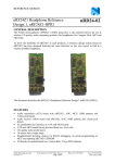
The following are the block diagrams of how the designers would ideally want to
set up the Exploding Alarm Clock Figure 2.3.1. The block diagrams depict how
the speakers connect to the main base station. The block diagrams also show
which parts can be considered related to each other by how they are grouped.
Main Base
Block Diagram
MP3
Decoder
(To Be
Acquired)
Charger for
Speaker
Batteries
(To Be
acquired)
Power for
base
(Research)
Display
(Research)
Microcontroller
(Research)
Transmitter to
speakers
(Research)
AM/FM
Receiver
(To Be
Acquired)
Blue - Wireless Connection to
Base
Red - Speaker Connection to
base for charging
Purple - Speaker and Volume
Control
Charger for
Speaker
Batteries
(To Be
acquired)
Internet
Connectivity
(Research)
Speaker 1
Speaker 2
Speaker Housing
Speaker Housing
Volume
controls
Speaker
(Research)
(To be
acquired)
Wireless
Receiver
(Research)
Battery
Holder
Battery
Holder
(To be
acquired)
(To be
acquired)
Battery
Indicator
Battery
Indicator
(Research)
(Research)
Speaker
Volume
controls
(To be
acquired)
(Research)
Wireless
Receiver
(Research)
Figure 2.3.1
7
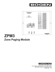
The designers decided to split up the administrative duties in a way that
corresponds with what they had any experience with Figure 2.3.2. The duties are
also split so that they grouped with the part of the system they are involved in
(i.e. all the speaker related duties are grouped together).
Main Base
Administrative
Duties
MP3
Decoder
(To Be
Acquired)
Charger for
Speaker
Batteries
(To Be
acquired)
Power for
base
(Research)
Display
(Research)
Microcontroller
(Research)
Transmitter to
speakers
(Research)
AM/FM
Receiver
(To Be
Acquired)
Charger for
Speaker
Batteries
(To Be
acquired)
Green - David
Pink - Branden
Blue - Nathan
Internet
Connectivity
(Research)
Speaker 2
Speaker 1
Speaker Housing
Speaker Housing
Volume
controls
Speaker
(Research)
(To be
acquired)
Wireless
Receiver
(Research)
Battery
Holder
Battery
Holder
(To be
acquired)
(To be
acquired)
Battery
Indicator
Battery
Indicator
Speaker
Volume
controls
(To be
acquired)
(Research)
Wireless
Receiver
(Research)
(Research)
(Research)
Figure 2.3.2
8
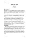
3. Estimated Project Schedule
The follow milestone charts were created before the designers had worked out
the details of how the Exploding Alarm clock would work. As far as they knew,
this wouldʼve been the most efficient way to get this project done.
Milestone Chart
Initial Design Doc
General Research
Final Design Doc
Clock
Launcher
Wireless Reciever
Net Connect for Base
Speaker+Base Connect
USB
Microcontroller
Radio/MP3
Buttons/Dials
Speaker
Volume Control
Battery Holder + Charger
Battery Indicator
Power
Display
Speaker Housing
Base Housing
Website (for clock setting) Design
Website (for Project)
September 1/2
September 2/2
October 1/2
October 2/2
November 1/2 November 2/2 December 1/2
Critical Design Review presentation
Project Documentation
Final Demonstration
Microcontroller
Clock
Power
Display
Buttons/Dials
Radio/MP3
USB
Speaker+Base Connect
Speaker
Speaker Housing
Volume Control
Wireless Reciever
Battery Holder + Charger
Battery Indicator
Launcher
Net Connect for Base
Base Housing
Website (for clock setting)
Chart 3.1
9
4. Estimated Project Budget
FInance Document
Cost
Part
Speakers
$10
Wireless Technology for speakers
$70
Internet technology
$20
MP3 Decoder
$20
Display
$10
Housing
$30
Micro-controller
$50
Power Supply
$20
AM/FM Radio
$10
$240
$300
Budget
This project will be paid for out of the group members pockets. All cost will be divided equally.
Chart 4.1
10
5. Research
5.1. Clock
The most simple, yet extremely important feature of an alarm clock is the actual
clock. In order to get this clock to work properly a number of components need to
effectively interface with one another to create the final clock display. The time
keeping frequency could be taken from the power source, converting to the
correct amount of hertz per second to account for the seconds for the clock.
However, this is not the most accurate solution, so this will not be researched or
used in the final design. A more accurate way of dealing with the time keeping is
to use a Real-Time clock chip. Some of these chips even have a built in crystal to
aid in keeping the accuracy of the oscillation eliminating the need to have an
external one attached. This would be the preferred method as it cuts down on the
number of parts in the design and reduces the overall complexity of the system.
Some microcontrollers include a real-time clock, so they would only need a
crystal added to the circuit to keep time accurately. This feature is not included in
all of the microcontrollers that were researched so it can not be assumed that this
will be the case. Therefore two different cases will be considered for research to
account for the possibilities in the final design. The first being that the
microcontroller does not include an internal clock and needs an external clock IC
and the second is where the microcontroller features an internal clock. The first
caseʼs research involves finding a part that would fit in to the design of the project
while providing the ability to keep time. There are a number of different ICs that
include all of the needed components for running the clock.
DS1307: This particular part is used in conjunction with a crystal oscillator to
handle the time keeping for the alarm clock. The part is added to the system
connected to the microcontrollerʼs I2C port to send the time through I/O pins. The
part has many features that are desirable in the final design of the alarm clock
and some of these features are listed below.
• Real-Time Clock (RTC) Counts Seconds, Minutes, Hours, Date of the
Month, Month, Day of the week, and Year with Leap-Year Compensation
Valid Up to 2100
• 56-Byte, Battery-Backed, General-Purpose RAM with Unlimited Writes
• I²C Serial Interface
• Programmable Square-Wave Output Signal
• Automatic Power-Fail Detect and Switch Circuitry
• Consumes Less than 500nA in Battery-Backup Mode with Oscillator
Running
• Optional Industrial Temperature Range: -40°C to +85°C
• Available in 8-Pin Plastic DIP or SO
The low power device would be a good asset to the design of the project, but the
schematic design needs to be considered in order to integrate the part. The basic
schematic design for this part is provided by the developer website and can be
11
seen below in Figure 5.1.1. The figure shows how it would be interfaced with a
microcontroller, depicted as the CPU in the diagram, and what other connections
need to be made to get the part to function.
Figure 5.1.1
(Reprint with permission from Maxim)
The cost of this part also needs to be considered when deciding a final part. The
price for this particular part is a little high, between $4 and $5, as far as RTCs go.
However, the features and the ease of implementation because of the simple
data sheets and application notes help its case. Integration of this part has some
dependence on the microcontroller that is chosen. If a microcontroller with a builtin real-time clock is picked then this part would be unnecessary. However, if that
feature is not included this would be a good candidate for choosing the final realtime clock controller.
M41ST84W: Another real-time clock chip that is under consideration is from
STMicroelectronics. This particular chip is an I2C serial chip that would be used
along with a crystal oscillator. The features that are included with piece would
help in the design of the alarm clock, mainly the built-in programmable alarm with
interrupt. Some other features that are included are in the list below.
• 400kHz I2C serial interface
• 44 bytes of general purpose NVRAM
• Counters for time and date
• 32kHz oscillator with integrated load capacitance (12.5pF)
• Package is a 16-lead SOIC
With these features and the correct schematic implementation, the alarm clock,
both alarm and time keeping, could be handled. The functionality of the part and
12
the combination of a quartz crystal oscillator would add simplicity to the overall
design. Along with the features that it offers, the cost, which is between $2 and
$3, needs to be considered when selecting a part to be implemented. The next
part that needs to be explored is the needed addition piece for microcontrollers
with built-in real-time clocks.
Crystal Oscillators: The crystal oscillator helps compliment the real-time clock
circuit by offering a precise frequency to provide a stable clock signal. The realtime clock, whether it is built-in to the microcontroller or a separate I2C, needs a
constant frequency so that it can get an accurate time from the frequency. The
seconds are derived by dividing the frequency till you get 1Hz per second, and
then using variations to get the other time components. The crystal oscillators
come in small packages with two pins that can be connected to the circuit to
send the frequency. The price varies depending on the package and the
frequency desired, but it can vary from $1 to $15. They are a simple component
to the system, but very important if accuracy is desired. The frequency needed
depends on the microcontroller or part that is picked, but this will be explored
more in the design section of the clock.
5.2. Display
The display is probably the most important part of the clock. For our design a
digital display of some sort is the most sensible. It will need to be able to display
time as well as other information such as a selected song since the clock will also
function as a mp3 player. Without out the appropriate display many of the
features of this clock are pointless.
Seven Segment Display: Seven segment displays are the most commonly used
displays in digital clocks. The provide the ability to display digits zero through
nine and a the letters a through f. This display is perfect for just displaying time
but it lacks the functionality we need for our design. It lacks the ability to display
all the letters in the alphabet or special characters which are common in song
titles. Its also doesnʼt have the ability to show current clock functions that we will
have like displaying what input the radio is using, if its a.m. or p.m., or if there is
an alarm set.
CFA-635: Another display option is the Crystalfontsz CFA-635. With is on built in
micro-controller, buttons for selecting options, free software for programming,
and built in backlighting it provides many options. It displays twenty characters
and for lines. This includes letters numbers and special characters it is also
capable of displaying graphics. The micro-controller include in this display is
completely reprogrammable allow us the freedom to use it for our purpose. The
only difficulty this may provide is interfacing it with what ever micro-controller we
use to control the main functions of our clock. Mounting brackets are also
available making it easier to build into the design of the clock. Customization of
13
firmware and hardware are also available from the factory. The CFA-635 is
shown below in Figure 5.2.1.
Figure 5.2.1
Reprinted with permission from Crystalfontz
SC2004: Another viable LCD display is the Silicon Craft SC2004. It is a 20x4
character display available in three different color options. The SC2004 has built
in flash memory allowing you to program and store user defined settings and
custom characters. It also allows you to display big numbers. This is great for the
clock function. By setting it display big numbers after a certain amount of time or
when not playing music it will look like a normal clock. The display uses a P3
serial interface to control it. Free software is available for testing the display and
for creating custom characters. All display commands are simply hex codes
readily available in the user manual. There are 3 digital outputs and 3 active low
inputs also built into the display. The digital outputs give us the ability to to use a
cursor to select something on the screen and send the selection out from the
display the main micro controller.
Touchscreen: A touchscreen would be the most flexible option of all. It would
allow for many different things. With a touch screen we could eliminate the need
for any other buttons on the clock. We could use softkeys within the display to do
everything. The downside to the touch scree would be the increased amount of
programming needed. The reliability of the whole system on that part also
increases. If something goes wrong with it then there is no way to do anything
with the clock. Another pro of the touch screen is the ability to display just about
anything we want such as song information, CD covers for songs if they are
available, time, and other important information. The main downfall of a touch
screen is cost because of the high cost we have to worry about something going
wrong with it. If something does go wrong with it or it breaks we may not have the
funds to replace it.
5.3. Internet Connection
One of the features the exploding alarm clock is going to have is the ability to be
set by the user when the user is not home. The only viable way of accomplishing
this is by connecting the main base of the alarm clock to the internet. This section
will not discuss the actual program that sets the clock (see the WebApp section
for more details on this) but will discuss the possible methods for connecting the
14
alarm clock to the internet. There are three possible methods that were thought
of: 1) having a wireless card inside the base of the alarm clock (Wi-Fi) 2) having
a bluetooth connection between the base of the alarm clock and the userʼs home
computer 3) having an Ethernet connection on the base of the alarm clock.
Wi-Fi: Using a wireless internet connection to connect the alarm clock to the
World Wide Web for on-the-go alarm setting has some pros and some cons.
Wireless networks are relatively easy to set up as they are not any more difficult
than a normal network. They would require the user to have a wireless router,
but those can be found at local stores for relatively cheap prices. New consumer
appliances like the Apple iPod, netbook computers, Pocket PCs, printers and
even DVD players are able to connect to wireless networks in the userʼs home.
Knowing that, many of the difficulties in letting the alarm clock connect to the
internet through a wireless Wi-Fi connection have already been solved by many
companies and manufacturers. The distance for a working Wi-Fi connection is
different for every router, though most routers provide about one hundred feet of
unblocked signal. As long as the user kept the alarm clock within that distance
from the router, the alarm clock would be able to recognize the network and
connect to it.
The alarm clock can be connected by having a wireless card installed inside of it
(which would require that whatever housing is used does not block or distort the
signal in any way), or by using one of the USB Wi-Fi dongles that would attach to
a USB port on the alarm clock. A wireless card can be bought for relatively low
prices as can USB dongles. Both average around twenty-five dollars. A company
called Lantronix makes a device that can attach onto a microcontroller in an
embedded system and allow it to have wireless capabilities. While designed
more for using the web in a casual fashion, this would work very well inside the
exploding alarm clock. It is pricey, however, with a MSRP of $299.
There are some serious questions to consider if a Wi-Fi connection is chosen.
Can the alarm access secure networks/would the user have the ability to input
the password for a network? If not, the user would have to be working with an
unsecured network would could leave their computers vulnerable. How are the
different networks displayed? The more complex/numerous the display data
required, the more expensive a LCD that display it will be.
Bluetooth: Another possibility is having a Bluetooth connection between the
base of the alarm clock and the userʼs computer. A “pro” from Bluetooth (that also
applies to Wi-Fi) is the lack of wires. Other than the Bluetooth receivers and
transponders, there is no other connection required. Bluetooth can send data at a
max rate of 3Mbps according to the article
How Bluetooth Works on howstuffworks.com. 3Mbps will be more than needed,
but its good to know that all the data that would be needed to be sent to the
alarm clock could be sent in a mere moment. A Bluetooth signal is moderately
weak, compared to other electronic devices. It is able to project its signal up to
15
about 32 feet. One would assume that the userʼs computer would be in the
bedroom or in the room next to the bedroom, so 32 feet should be sufficient
enough to cover the distance between the alarm clock and the computer.
An interesting aspect of Bluetooth is that up to eight devices can be connected
simultaneously. This will only be useful if the speakers end up being connected to
the base via Bluetooth. That way the alarm clock can be designed with the two
connections between the speakers and the alarm clock base, and then have the
connection between the base and the userʼs computer without worrying about
any data being lost or misread (with misreading meaning data meant for the
speakers being sent to the computer or vice versa). On that same thought,
security can be part of the Bluetooth package as well. Bluetooth devices can
established trusted relationships with other devices and only accept data/send
data to those devices. Unlike other Bluetooth related devices, if used in the
speaker system, the “accept or deny data transfer” method to security would be a
hurt, not a help. It would keep the user from being able to set their alarm clocks
from an away-from-home location and from listening to music in a carefree
manner.
A Bluetooth connection is also an automatic connection so there would be no
worries that the user connected to the wrong network, or that they did not set up
the Wi-Fi connection correctly or anything of that nature. Bluetooth is also
relatively low powered. This will work well for the base of the alarm clock, as
there will be no worries about the drain on the userʼs electricity bill due to some
power hungry system. There are things like shoe sole wear-out sensors and GPS
shoes that are in the works according to an article on bluetooth.com called
Experience Wacky Applications, Bluetooth enabled stethoscopes, Bluetooth
enabled dresses (that light up when the user gets a call) and more are also out
there, so the power drain of Bluetooth on any system can be made very, very
small as evident by these devices.
Ethernet: The final viable method for an internet connection for the base of the
alarm clock is an Ethernet connection. Ethernet is the default method of internet
connection for computers and other stationary internet ready devices. As
Ethernet is a wired technology, the distance between the userʼs modem or router
and the base of the alarm clock is limited. Most Ethernet cables are going to be a
few feet long, though there are some that are made longer. This limit would mean
the user would have to have their router in the same room as their alarm clock.
The Ethernet connection would treat the alarm clock as just another computer
device connected to the network.
There would be no worries about data being lost between all the connections,
since the speaker connections are a wireless technology and the Ethernet is a
wired connection. There is not any way for the speakers wireless connection to
interfere with a wired Ethernet connection the same way that having them all
being the same type of wireless connection can theoretically cause. An Ethernet
16
connection is going to have good security as there is no way of someone outside
of the household (hacker of some sort) to interfere the same way it is
theoretically possible with wireless technologies (like Bluetooth and Wi-Fi).
Fortunately for the design of the alarm clock, almost all microcontroller
companies have some form of an Ethernet shield that allows there
microcontroller to connect to the internet via an Ethernet connection. They are
easy connections that are built for the specific microcontroller. This is helpful
because it means if Ethernet is decided upon as the way to connect to the
internet, then nothing should have to be changed in the microcontroller
department to accommodate this choice.
5.4. Power
Every device built needs to be powered in some way. The power source chosen
needs to be efficient and stable. If the power supply is not stable enough and the
clock loses power frequently the user will never have the correct time and will
constantly have to reset their clock to the appropriate time. This is not ideal in a
clock. Ideally you want your clock to never lose power. So that no matter what
happens when you fall asleep your clocks going to have the right time and your
alarm is going to wake you up when you want it to.There are many ways to
achieve this and some possibilities will be talked about below
Batteries: One of the most common ways of powering an electronic device is
batteries. This mainly for portability. Batteries are easily replaced and allow your
device to function even during a power outage. There are many different battery
options and they are available both rechargeable and non-rechargeable. Since
we are going to be using many different functions with this clock this is not the
most efficient way to power. The speakers are planned to use rechargeable and
will use the main base as a charging station so the will draw a great amount of
power. The main base will also charge whatever device its is playing music from
so that the users device wonʼt have a dead battery every time the need to use it
after using it with their clock.
Although not the most efficient way to power the whole system batteries arenʼt
such a bad thing to have. Bye including batteries as a backup. This could save
many users from waking up late do to a power outage. It is very common that a
power outage and a person loses their all there clock setting such as alarms and
times. By backing up the systems power with rechargeable batteries we can
protect the users from this occurrence. This is also nice for if you want to move
your clock to another location in the house. You can just unplug it move it to
where you want it and then plug it back in and you do not have to worry about
resetting it.
17
Photovoltaics: A readily available power source is the sun. Pumping tons of
energy to earth every day it is a ample power supply for a clock. Photovoltaic
cells are very common currently amongst people trying to go green. It is a very
clean power source. Although great for electrics cars and many outdoor items its
is probably not the best way to power a clock radio that is mainly meant for home
use. It is possible to use photovoltaic cells to charge a battery that will power the
clock but from a designer prospective this isnʼt the most cost effective method. It
would also create more complicated circuitry.
If we were looking to create a self sustaining clock that a person could take
anywhere this is probably the best option. The clock would be completely
portable and you would almost never have to worry about how to power it or
worry about changing batteries or finding some where to plug it in. As long as
there was some sort of sunlight you could basically power the clock anywhere.
AC Power: The easiest and probably most straight forward way to power the
device is AC power from a wall receptacle. This is the most common way that
house hold appliances like a clock are powered. The complication from this
comes in when distributing the right voltages and currents to parts. Aside from
this there are really no downsides to this. The power received from a wall socket
is stable and constant. As long as the user has power in there house they donʼt
have to worry about the clock cutting off.
AC Power adds the least additional cost to the project. The power source is the
wall receptacle. This is an external power source that is already in place in the
users environment. The parts need for the circuitry involved with interfacing this
power supply are very common and inexpensive. This will making getting them
all together an easy process.
In order to make the clock if more efficient we have the option of combing an of
these ideas for power. A common example is the combination of AC power and
batteries. With this even if the user loses power in their house they clock will still
function until the batteries die. This also allows the user to unplug the clock and
move it to another place. During this move the clock will stay on and it wonʼt lose
any information. It also gives the user the ability to take the clock with them
somewhere if needed and they wonʼt need to find some where to plug it in.
5.5. Alarm Clock And Speaker Housing:
PVC: PVC was one of the first materials thought of as housing for the project. It
is the engineering do-all material. PVC is a very cheap material, current prices as
of this writing, put it at about eleven dollars for a one foot by two foot, quarterinch thick sheet. PVC is a very lightly weighted material. The aforementioned
sheet only weighs about four pounds. As shown by the last source, PVC is very
easy to acquire. One need not go far out of oneʼs way to get it. Any local
18
hardware store or an all-around web provider should have PVC in stock in some
form.
PVC does have some downsides, however. Its ability to stand up to intense
pressure is limited. Its ability to stand up to the constant slamming into the
ground for a decent height is limited (the type of situation it might be applied to if
the speakers are being projected off tables) onto hard floors. This has a flip side:
its low strength also means there are no worries of damage to the floor by the
falling speakers. PVC is also easy to shape, so there should be no difficulty in
forming it into the shape of an alarm clock. But PVC is also not an appealing
substance, neither in appearance or texture. It looks cheap, and it feels cheap.
But more important than any of that are the health concerns. PVC is a very
controversial material and whether or not the claims have any merit, a consumer
is not going to want an alarm clock that could possibly hurt their reproductive
systems growth.
Metal: Metal is an understandably generic term, but in this case its meant to be
aluminum, steel and/or iron. Metal is much more expensive than PVC. For a
sheet of aluminum, one foot by one foot and only one-eight of an inch thick it
costs about fourteen dollars, three dollars more than a larger size of PVC. Steel
is even more expensive with it costing two dollars and forty-eight cents for
something that is six inches by eighteen inches but only .008 inches thick. But
something that is thin would not offer the protection that one would go to metal
for and to get that you would have a very heavy housing. While its increased
density would give it a much needed strength to absorb the force of falling to the
floor, make it too strong and it could actually damage the floor.
Like PVC, metal would be very easy to obtain. The local hardware store and
online stores like amazon.com would be the easiest places to find it. Unlike PVC,
metal will be a bit harder to shape, because of its difficulty to cut. But it would
look nice, as the metallic look is very slick. So it would be appealing to the
prospective users to have a metal housing for the alarm clock. A final, and
probably most important, point is the fact that metal blocks signals. The speakers
and base are going to wirelessly communicate with one another and having them
the transmitters and receivers in a metal base may greatly diminish their range.
Wood: Wood was mostly considered because of the aesthetics of it. Wood can
be shaped and formed very easily. Having an alarm clock shaped out of wood
would be very pleasing to the eye. It would give a very old-timey, retro look to the
clock. Wood would be easy to acquire, as most varieties of it are readily
available. Wood is also very, very cheap. A piece of dried dimensional lumber
that is two inches thick, four inches wide and ten feet long is only three dollars
and sixty-two cents.
But an alarm clock that has a two inch thick cover is not going to be very
comfortable for a user to own. With two inches thick all around of just the
19
housing, it would be a very bulky device. However, the wood that a store like
Home Depot would provide would not stand up to the constant dropping to a hard
floor. It would eventually damage the casing and fall apart. It would not damage
the room in anyway though, so that is a plus in the wood category. However,
since it is wood it cannot be very safe to leave them in an environment where,
under bad conditions, sparks could fly.
Glass: Glass is probably the least likely to be used of all the solutions for housing
that were thought of. Glass is moderately expensive. The cheapest place to get
them has some pretty atrocious shipping costs. What would normally be just a
couple of dollars for a few square footage of glass at .1 inch thickness increases
a lot when trying to ship anywhere long distance. Local stores sell glass, but it is
much more expensive, and it is not in usable quantities. Glass is not as light as
PVC is or as wood is either. It would be more difficult for the user to move this
alarm clock or carry around the speakers. And that makes it harder to see glass
as a viable option if it becomes cumbersome for the user. The transparency of
glass does increase its appeal, as see-through objects are very popular.
Glass would be very difficult to mold it to an alarm clock shape. Someone with
extensive training would need to be found to shape and cut the glass, and their
services would not come cheap. And more importantly that that, glass would not
work for the speakers. If someone was to drop something glass from their table,
it would crack, it would shatter and it would break. This alarm needs to be made
to handle more than one time going off.
Plexiglas: Plexiglas is a material with a glass-like transparency, but without the
weakness and extra weight. Plexiglas can be easily bought from local retailers
(though their selections might be small) or from online vendors. A sheet of
Plexiglas one foot by one foot and 1/8 of an inch thickness goes for twenty
dollars. Plexiglas is the material used in WWII era planes to protect the pilots
from bullets, according to Plexiglass Primer, so it should definitely be able to
handle being knocked to the floor every day. Plexiglas is half the weight of
glass , so it is very user friendly. Not only that, but the light weight would make it
good for preventing any room damage from the falling speakers. And because of
its glass-like transparency, it has all the benefits associated with being seethrough. Plexiglas also has the ability to withstand very high temperatures, which
is perfect for something that will be handling electrical parts in close proximity to
one another.
The one negative aspect of Plexiglas is its ability to shape. While not as difficult
as attempting to reform metal, Plexiglas has the strange ability to crack if cut too
slowly (say with a jigsaw) or to have the edges start to melt if cut too quickly. It
would either take multiple attempts to figure out the perfect speed, or someone
would experience with cutting Plexiglas could be hired/volunteer their time.
20
Polycarbonate: Polycarbonates, like Plexiglas, are a form of thermoplastics.
Polycarbonates have all the “pros” of Plexiglas, and in fact, have better versions
of those “pros”. One of the brand names, and the most common form of a
polycarbonate, is called Lexan. Like Plexiglas, Lexan is very impact resistant.
Lexan is able to absorb “the equivalent of 4300 pounds of TNT detonated from
115 feet away”. Anything that can easily withstand TNT should be able to handle
dropping onto a tile floor and/or being hit with the spring system everyday. In a
more common use, Lexan is used in vending machines. That is what the formerly
glass cover is made out of.
It is also flame resistant, which is very good when it comes to housing
electronics. Not that the alarm is expected to actually catch afire, but it is good to
know that it can handle any extreme heat that may be generated by the electrical
parts that make it up. Lexan is also relatively cheap. At Amazon.com, one can get
a one-fourth inch thick, twelve inch by twenty four inch piece of Lexan for a little
over twelve dollars. Compared to the prices of Plexiglas, that is a great deal.
Lexan is also just as easy to obtain as the Plexiglas; it can be found at many
retailers online and at local home improvement stores.
Because Lexan is transparent, like glass and Plexiglas, it will have all the seethrough benefits talked about earlier. But unlike glass and like Plexiglas, Lexan is
a light material, so there are no worries about it being too big or too bulky for the
common user. And because of Lexanʼs strength, thinner pieces of it can be used
while still achieving a high impact resistance. Lexan is also safe in all
environments. Underwriters Laboratory approved Lexan for use in electronic
devices and Lexan meets the FDAʼs requirements for use with food and in the
home.
5.6. Radio
A minor, yet important component of the design is the radio for the alarm and
casual listening. Even though radio is not the most popular music listening choice
it is still an expected feature of an alarm clock, so it will be added to incorporate a
larger audience of consumers. There are a number of available options for using
a radio frequency tuner to implement a radio into the design.
LV24003LP: One of these options is the LV24003LP single-chip FM/AM tuner IC
for portable electronic devices made by Sanyo Semiconductors. This particular
device comes with a number of desirable features that are listed below.
• No external components are necessary
• Fully integrated low IF selectivity and demodulation
• Very high sensitivity due to integrated low noise RF input amplifier
• Low power Standby mode
• 3-wire bus interface including Data, Clock, NR-W
This particular chip is made for mobile device applications but it could be
transferred to the design of this project in an easy way. Omitting some of the
21
unneeded features such as buzzing and the headphone amp could be easily
done by ignoring the pins and not incorporating it into the design. The main
hesitation of this chip is if it does not implement as well as a non mobile chip.
However, looking at the schematic design for the chip in the data sheet shows
promise to the ease of implementation into the final design.
LA181: Another chip that could be considered is very similar to the previously
described chip only this one is not specifically for mobile devices. It is made by
the same company and is called LA181. It has the same features as the other
chip, except for the lack of built in mobile applications. It also is an older chip, but
it is simple in its design and implementation, which could be helpful in interfacing
it with the rest of the design.
SPK-TFM-1010: This part is a breakout board from SparkFun electronics that is
based off of the AR1010 integrated circuit from Airoha. Some of the basic
features included in this part are listed below.
• 3.3V @ 11mA
• 76-108MHz supported
• 100mV audio output
• Stereo output
This part has some pros and cons that are at very significant ends of the
spectrum. The pros of this part are that it is a small chip that can be easily
integrated into the design with no additions other than an antenna and that it can
use a simple command set over I2C or SPI interface. The chip also has the
benefit of allowing direct connection of audio output, because all of the needed
components are contained on the breakout board. The two main cons for using
this board is that it does not include functionality with AM and the cost is relatively
higher then the other chips that were researched. The lack AM radio functionality
is not the biggest of downfalls, being that FM is more popular of a choice. The
cost is also manageable at a $10 price tag. So, overall the pros out way the cons
making this part a good candidate for the final design.
TA8127: One last chip design to consider is the TA8127 by Unisonic
Technologies. After researching all of these different tuner chips it is apparent
that they are all extremely similar. As a result, the TA8127 has about the same
features as the other two. The interesting feature of this chip is its low operating
supply voltage of 1.8V. Deciding which tuner chip to use is a matter of ease of
integration with the rest of the design, and cost. The amount of features is not a
factor in part selection because of the lack of extra features that could be added,
so in other words, the bare minimum is all that is needed. The tuner is not the
only thing we need to complete the FM/AM circuit. The antenna is what picks up
the signals to send to the tuner and is therefore crucial to the circuit. The antenna
finds the modulated sine waves in the air and sends them to the receiver so that
they can be demodulated and converted to playable data. The antenna is simple,
yet important to the radioʼs design because with out one the receiver would not
be able to pick up the modulated waves unless it was close to the transmitter. An
22
antenna can be a simple stick of metal that is attached to the antenna-in port of
the module. However, for this design a simple radio antenna purchased from any
electronics store will be sufficient. One example is the Pyramid 3800 AM/FM
antenna, which is around 10 dollars. One other thing that needs to be added is
the HMI for the radio control. The HMI is discussed in the MP3 decoder sections
and the same information can be applied to this section. The only difference is
that it the controls will be tied to the radio instead of MP3 controlling. Choosing
the parts for this design is as simple as picking a simple part that is easily
implemented into the design.
5.7. MP3 Decoder
A key component to the Exploding Alarm Clock design is the ability to play MP3
music files as the alarm and for casual listening. In order to do this the MP3 files
are taken from the mass media device and passed to the MP3 decoder so that
they can be decoded and passed to the digital to analog converter and then on to
the speakers for output. The reason this is necessary is because MP3 files are
encoded in lossy data compression so that the files are smaller. The storage of
the files becomes smaller because of compression, but they need to be decoded
when being accessed for playing. The MP3 decoder is implemented through an
MP3 decoder chip, or MP3 decoding software on a programmable chip such as a
microcontroller. There are a few possible options for MP3 decoding for our
design.
AT32UC3B: The first involves using the AT32UC3B chip, which is further
described in the Memory Storage and Interface section. This microcontroller chip
would enable the interfacing of USB and SD cards as well as implementing an
MP3 decoder in software. The great thing about implementing the MP3 decoder
in software with this chip is that the software already exists on the developerʼs
website in an application note. Modifications would have to be made but the
general layout and decoding is already coded. This would ease the pain of
writing a decoder from scratch which would be very difficult because of the
extensive knowledge of the encoding process of MP3ʼs that would need to be
known. Some of the things that would need to be added in order to make the
MP3 decoding process complete include adding a user interface code and parts
for playback selection. Although this is not exactly part of the MP3 decoding
process, it still is important to give the user the option to select which MP3 to
play, and also give a play pause feature. Using the AT32UC3B for MP3 decoding
would give us the option to add buttons to the general input/output pins and
modify the software code to use these inputs as playing commands. Another
option would be to send the data to the main microcontroller and attach the user
commands to that microcontroller instead of the one that does the MP3
decoding. Regardless of the actual routing of the data, the user needs to be able
to have the control over the MP3 data being decoded. The different kinds of user
input devices will be discussed at the end of this section, after other MP3
decoders are reviewed.
23
VS1033: Another MP3 decoder that shows promise is VSLIʼs VS1033 MP3
codec IC. This particular chip has some very interesting features that would make
it a powerful addition to the design of the alarm clock. Some of these features are
listed below.
• Built in decoder for MP3/AAC/WMA/MIDI
• Streaming support for MP3 and WAV
• Bass and treble controls
• On-chip stereo DAC with no phase error between channels
• Available interface for external DAC
• Software to edit the 8 general purpose input/output pins
• Low-power operation, including separate operating voltages for analog,
digital and I/O
Implementing this chip would be easy enough, because it just receives the data
from the storage device and then passes on the decoded information on to the
speakers, because of the on-chip DAC. The on-chip DAC would probably be
sufficient for the digital to analog conversion so it would replace an external chip
reducing the amount of parts needed in the final design. It would also be wise to
consider this chip because of the different formats that it is capable of decoding,
which give the consumer more of an incentive to purchase because of the
versatility.
BU9438KV: Another worthy component is the BU9438KV by Rohm
Semiconductor. This chip is very versatile much like the VS1033 because of its
ability to decode a number of different formats. What sets this chip apart is the
built in function of reading from USB and SD. This would eliminate the need to
come up with another interface for memory storage and cut down on parts
needed. There are a number of features that would be useful to this design that
are included in the BU9438KV arsenal. Some of the features are listed below.
• USB and SD memory audio play function built in
• USB 2.0 Full-speed host controller contained
• SD memory card controller contained (SD/SDHC/miniSD/microSD/MMC)
• Decoder included for MP3/WMA/AAC
• Integrated LDO to eliminate the need for an external core power supply
• Integrated PLL to eliminate the need for an external crystal
• On-chip DAC
• Built in LED support
The chip comes in a VQFP64 package, meaning it has 64 lead pins. The data
sheet provided by the producer website is very simple and easy to understand
which helps in the choosing process because some of the data sheets for the
other options are full of unnecessary data making them more difficult to decipher.
STA013: One last MP3 decoder that could potentially be used in the final design
is the STA013 Chip. This chip is older compared to the other chips that have
been researched, but that also helps with the amount of examples available on
the internet. The chip just has the standard MP3 decoding option and needs to
24
be configured with an external DAC in order to do the proper conversions for
audio playback. The main reason to use this particular chip would be to keep it
simple. The chip has the bare minimum for MP3 decoding and is very simple to
implement. Obviously the user might like the choice of having more then just
MP3 for a file format choice, so this chip may not be the best choice. Also, the
fact that the other chips looked at have such features as built in USB and SD
interfaces, as well as a built in DAC could lead the project to use a different
decoder for the final design. Simplicity is not always the best way to go when
thinking about marketing a product, because consumers always want the latest
and greatest with the most features. The part selection process will take in all of
the factors, such as cost, features, ease of implementation, and ease of user
interface integration, in order to pick the best part for this project.
Human-Machine Interface: Another important part of the MP3 process is the
Human-Machine interface so that the user can control the playing of the songs.
There are a number of ways this could be accomplished all to the same effect,
just different process. One possibility would be the implementation of buttons
integrated into the circuit as switches. These switches would let the input/output
pin, which are receiving a constant voltage, go to ground when ever the buttons
are pushed. This would act as an event to the handler and processed depending
on what the input was tied to. For example, if there was a button for the input to
the play/pause button and the button was pushed, the input would go to ground
and the software for the handler would interpret that as a play/pause function and
then process it as such. These switches are the very basic form of user interface
and therefore are cheap and easily implemented. A couple of buttons would need
to be purchased so that each function could be implemented. There are other
alternatives however that need to be considered. Another option is using a
keypad that has all of the switches on a PC board already and can be connected
to a microcontroller to send the signals for pressed buttons. This configuration is
the same as the button/switch configuration just with more of them consolidated
on to one board. The main problem with this is finding a non-customized keypad
that would fit the amount of buttons needed for implementation. Customized
keypads could be purchased but the amount of time and money spent in
acquiring one does not seem worth it. A specific number of buttons is better
handled by purchasing individual push button switches. The last possible solution
that will be discussed is an infrared remote control. This could be implemented
along with one of the other designs to enhance the user options. The Exploding
Alarm Clockʼs overall design includes casual listening functionality with the
speakers detached. The user would probably appreciate the ability to switch
songs, change the volume, and pause the song with out pressing the buttons on
the base. This is important because the user may not be close to the base when
using the MP3 player, perhaps across the room. This could be implemented by
using an IR receiver connected to a microcontroller to handle the process
received. The remote is the easy part of the implementation because any IR
remote can be configured to work with the IR receiver. An IR receiver typically
consists of the optical lens and 5 lead pins. An example of an IR receiver can be
25
seen in Figure 5.7.1, which displays the TSOP853 made by Vishay
Semiconductors. The 5 lead pins on the bottom of the part correspond to three
different grounds, a supply voltage, and a data out.
Figure 5.7.1
(Image courtesy of Vishay Intertechnology, Inc.)
The receiver sends the output through the data out pin to the microcontroller
where it can process the commands accordingly. These are just some examples
of the user interface to the MP3 player portion of the design. The final selection
process of the implementation will take in to consideration the cost, ease of
implementation, user friendliness, and integration of software in the design.
5.8. Memory Storing and Interfacing
With the ability to play music files in place, the alarm clock will need a place
where it can store the files. The key issue is to find a device interface that can
hold music files and pass them to the MP3 decoder for playback. There are a few
options available to us, all within consideration for the caliber of this project.
These options include USB flash memory, SD card memory, and iPod
connectivity and playback. All of these options would be used to store music files
for playback for the alarm, and for casual listening. To clarify, iPod connectivity
would be through the standard iPod cable, which ends in USB, and enable the
use of the iPod as normal with the sound producing from the base and speakers
of the alarm clock. They would also need a standardized convention or method to
pass information to the MP3 decoder, which is technically called the interface. All
of these conventions have their pros and cons and need to be weighed heavily to
pick the best media for this design.
IPod: To start with a difficult one, iPod playback for this particular implementation
seemed unattainable for this scale of project. Appleʼs need to control the market
for iPod related products has led them to produce an authentication chip that is
required to decode the interface for the iPod. Popular Mechanics Magazine had
an article about the chip and the grief of dealing with Appleʼs desire to dominate
the market that explained what the chip did. This excerpt is from that article, “The
chip works like a silicon key that unlocks streaming video functionality on
26
iPhones and iPods and generally authorizes the devices to work with approved
accessories. The advent of the “auth chip” made it impossible for any third-party
company to produce iPod-compatible gadgets without dealing first with Apple—
the only company selling the chip.”1 This chip is bought by third party companies
for a steep price, not to mention the royalties included in producing an Apple
related product. An attempt was made to contact Apple in regards to receiving
one of these chips for educational purposes, but the request was never
answered. All designs of iPods, excluding the Touch, can be used as a mass
storage device, so in reality an iPod could be used through USB to play music
files. However, it would not play the files that were put on the device through
iTunes, the media player for adding music to the iPod. The songs that would play
are those that were manually added with drag and drop to the file system.
However, there are microcontrollers found to handle MP3 decoding that claim it
can be used to interface with the iPod, iTouch, and iPhone. Also, pin schematics
for the standard connection to the new iPods have been found on the internet
and could therefore be used to implement a connection and interface. The pin
printout of the standard iPod connector is shown in Figure 11.2.1 in the
appendix. With the pin configuration and description, it is possible to disassemble
a standard iPod connector and modify it to fit the needs of this project. However,
it is important to know which pin is which so that you connect to the write ones.
The pin layout for the physical connector is seen in Figure 11.2.2 in the
appendix. It shows the physical location of the pin in relation to the back side of
the connector. With the ability to design a custom cable and have all of its pins
mapped and described, the iPod can be interfaced to the design using a PIC
microcontroller. A PIC, or peripheral interface controller, will act as an information
buffer between the storage device or media player, and the MP3 decoder. These
are a prime choice for interfacing because of the cost and simplicity of
programming. They are programmed using any of the programming languages
that are available with PIC compilers. Some examples of these are C, Basic, and
Pascal. This groups strong point is in programming with C so that is the compiler
language to be used if this is to be implemented. After the program is written and
compiled it needs to be passed to the PIC using a programmer. The programmer
will either be purchased or borrowed from the lab. There are obviously numerous
other choices for interfacing out there, such as the AT32UC3B0256 made by
Atmel®. This microcontroller is a very tempting choice as it would potentially
have the capability of interfacing with all of the choices, iPod, USB, and SD.
Atmel® also provides application notes that are sample programs to guide you
through the steps of programming the microcontroller to do what you need it to
do. The application note that would be pertinent to this design would not include
the interfacing for the iPod, but it would not be extremely challenging to add that
on to the program. The good thing about this application note is that it includes
the interfacing for the USB flash drive and the SD card, so that all three of the
choices could be implemented with little effort. It also includes MP3 decoding,
which would cut down on the number of parts needed to implement this design.
The software architecture for this design is shown in Figure 5.8.1 and displays
the flow of the software application.
27
Figure 5.8.1
(Reprinted with permission from Atmel)
The diagram shows how the information is passed through the application
including MP3 decoding and the mass storage interface. The iPod feature is
shown as not delivered, but the option is available, so it could be implemented.
One of the factors that need to be kept in mind when choosing which chip to
interface with is cost. The cost of the PIC can range anywhere from $2 to $12
depending on the speed and amount of RAM. The Atmel® chip is around $8, but
the fact that this chip would act as the interface and the decoder needs to be
taken into account. Both of these options will be kept in mind when deciding a
final design solution for interfacing. As a result, connection of the iPod for music
playback is feasible and will be considered as an option for the music playback
feature of this project, which will be discussed in the design portion of this
section.
USB: The next option available for implementation is through USB flash memory.
The implementation of a USB interface for the storing and reading of files from a
flash drive would prove to be useful and user friendly, as well as allow for mass
storage devices such as simple music players that use the mass storage device
class along with FAT file system to be used for playing music. The selection of
the MP3 decoder determines how difficult the implementation of USB flash
memory would be. Older MP3 decoders do not come with the proper interface to
deal with USB data transfer, but chips are now available with the interface for
USB already built in to the decoder. The chips with the interface already
integrated would be preferable as to reduce the number of parts and the
complexity of the overall design. One step further would be to get a
28
microcontroller that dealt with the MP3 decoding as well as the data transfer and
connectivity of the USB flash drive. These are being greatly considered as they
would reduce parts, and complexity. An example of one of these microcontrollers
is the AT32UC3B0256 made by Atmel®, which is described in the iPod section
above this section. The Atmel® chip would be useful as it comes with the
application note that includes the interface to the USB, as well as the MP3
decoder. This would be useful as it reduces the number of parts in the design as
well as the amount of code that needs to be written. The code obviously needs to
be edited to fit the parameters of the projects design, but the overall ground work
would be there through the application note. Another solution to interfacing with
the USB is to use a PIC microcontroller, like discussed in the previous section.
The PIC needs to be implemented with software written to interface with the
USB, which would need to include the mass storage class. Application notes
could possibly be found on this to help with the coding, but it depends on what
PIC you get. The Atmel® still seems like the better option for interfacing because
of the features it provides. USB would seem a more logical decision for memory
storage because of cost, user friendliness, capacity, lifetime, and durability. The
cost of USB storage devices is decreasing while the amount of storage is
increasing. Kingston just recently announced the release of a 256 gigabyte flash
drive for around $900. The price may seem a little steep, but the price of smaller
size flash drives has decreased as a result of the advancement in technology.
This is just an example of how much the technology changes in such a short
time. Now someone can buy an 8 gigabyte USB flash drive for around $15. This
makes it a financially wise choice for memory storage as it is feasible to expect
consumers to purchase the alarm clock and a separate USB drive for memory, if
by rare chance they do not own several already. Though most consumers would
find it irrelevant, USB flash drives have a high reusability in the spectrum of write/
erase cycles and data retention. Some flash drives allow up to 1 million write/
erase cycles which would add to the reusability of the product by allowing data to
be changed numerous times. Also, most USB flash drives have ten year data
retention making them last long enough without replacement. Another redeeming
benefit of using USB is the transfer speeds. Even though they are not as fast as
hard disks, typical drives claim a speed of 30 megabytes per second for reading.
The writing is not as fast and is usually about half of the read. This is faster then
some of the alternatives such as lower end SD cards. However, SD cards have
other attributes that would lead them to be a good choice for implementation in
this project.
SD Memory Card: An interesting alternative for memory storage is the Secure
Digital memory card. This memory card has a relatively low cost and high storage
capacity. The regular SD standard has a storage capacity of up to 4 gigabytes.
This has been improved upon in result to the improvement of the storage
technology, in the form of two newer standards. The currently prominent standard
is the SD High Capacity, or SDHC, which has a capacity of up to 32 gigabytes.
Physically these SDHC cards are capable of capacities up to 2 terabytes, but the
standard limits them to 32 gigs. This will eventually change in the recently
29
announced SD extended capacity standard, or SDXC, which has yet to be
completely standardized and produced. Of course there are other types of SD
cards such as the miniSD and the microSD, but these do not have any changes
from the regular cards except for the physical dimensions and can easily be used
with standard SD slots with the use of adapters. For this particular project it
would be beneficial to implement the SD 2.0 standard if it were to be used as a
form of memory storage. The 2.0 standard includes compatibility with SDHC
cards as well as backward compatibility for the regular SD cards. The speed of
the convention varies depending on the card, but can range anywhere from .9
megabytes per second for basic cards, 10 megabytes per second for some
SDHC, and around 30 megabytes per second or higher for high end cards.
These speeds are based on the cardʼs maximum read times while the write times
are usually slower. Using this popular implementation of memory storage would
seem useful as it is already a common because of itʼs many other applications in
cell phones, digital cameras, and game consoles. The interface is tricky part of
implementation for the memory transfer, and for the SD card there are three
different modes for transferring. One-bit mode is transfer mode for SD that has
separate channels for data and commands. Four-bit mode uses some extra pins
to send more then the one-bit mode. SPI mode is specific for microcontrollers
and a more simplistic form of the SD protocol. The device for transfer will
determine which transfer protocol will be used, so the final decision will be
elaborated on in the design portion. However, more than likely the SPI will be
used because of the choices narrowed down for transferring. So far the main two
options for the transfer are the PIC microcontroller and the Atmel®
microcontroller chip described in the previous sections. These both would be
easy enough to use for interfacing with the SD card. Out of all of the choices for
memory storage SD cards seems to be the easiest to implement because of the
sheer number of examples and software application notes out there. SD is
implemented in many applications as a memory storage unit, and therefore there
is a lot of documentation on how to code the interface. The most common chip
used to interface with SD is the PIC microcontroller but this does not mean that
the Atmel® microcontrollerʼs implementation would be any less difficult. Because
of the application note that can be downloaded to go along with the Atmel® chip,
interfacing it with the SD standard is simple. Still the favor is put upon the Atmel®
chip because of its ability to interface with USB, iPod, and SD. It also stands out
from the PIC because it can be used as a MP3 decoder as well. If the Atmel®
chip is used in the final design, it would be possible to implement all three of the
memory storage choices, because of the interfacing options that come with the
chip. Another interesting candidate for the interfacing portion of the memory
storage units is the MP3 decoder BU9438KV made by Rohm Semiconductor.
The full specification of the part is discussed in the MP3 decoder section, but the
main reason it could be used for interfacing is discussed here. The chip comes
with a built in interface for USB and SD card reading of music files. This would
prove to be very useful as it would eliminate the need to program the chip
heavily. The sheer ease of implementation makes it a very worthy candidate for
implementation. When choosing a final medium for storage things that need to be
30
kept in mind is the storage capacity, transfer rates, cost, interface
implementation, user friendliness, and durability. All of these things will be
considered when implementing the final design.
5.9. Microcontroller
The microcontroller is perhaps the most important component of the design, as it
acts as the brain. The main functions it serves are telling the other components
what they need to do and handling the data flow from one unit to the next. They
also provide the connection and interface between the different modules and
provide the user with the ability to program it to do what ever the user desires.
For the design of the project it is necessary to find a component that can handle
all of the different functions required, such as, running a clock, LED screen
output, and sending and receiving data in order to perform tasks such as
launching the speakers and setting the time. The amount of things that need to
be handled in the specific design might call for the use of more than one
microcontroller to control different parts of the clock. Even though it would be
possible to use one microcontroller for the whole design, breaking things into
modules each with their own microcontroller might help to reduce the complexity
of the overall design and cut down on debugging troubles. Before the decision of
how many microcontrollers are going to be used, different microcontroller chips
need to be explored to see the options and varieties that will help implement the
clock in its final design.
PIC24FJ256GA10: The PIC microcontrollers are known for their simplicity and
ease of integration into complex and simple designs. Naturally these would be
explored when dealing with the selection process of the microcontroller for this
project. The first PIC that was researched was the PIC24FJ256GA10 family of
chips. The reason this is considered a family is because this is the general term
given to the set of microcontrollers where the only difference is the pin count. The
difference in pin count results in different amounts of available ports. A pin
package, either 64, 80 or 100, will be chosen depending on the amount of pins
needed in the final design. The chip has some desirable features that need to be
put in to consideration for the final design of this project. The key specifications
pertinent to the project are listed below.
• 16-bit architecture that has CPU speeds of 16 MIPS
• Program memory of 256 KB to providing ample room for the program
• For the lowest pin package: 53 I/O pins
• Built-in power managed modes for optimum low power running
• EEPROM emulation capable to eliminate the need for separate EEPROM
component in the circuit design
• Supports Capacitive Touch applications incase Touch screen is
implemented
The chip would support all of the needed peripherals with no problem, as well as,
run the clock and other necessary functions. This powerful chip is possibly
overkill for the projectʼs needs, but this leaves no doubt that the part is capable of
31
handling the needed processes and functions that would be required. The chip is
roughly $6 so the cost of this unit is not particularly a cause for dismissal. An
alternative to using a chip that might be to powerful for the design would be to
use a smaller version of the same chip. The PIC24FJ64GA series is about the
same chip only with a smaller instruction memory of 64 KB. Because of the
nature of the project, and the size of programming space needed, this might be a
better solution. The price of this chip is smaller but only by $2, so the price
difference is relatively negligible, unless youʼre looking at it from a business
direction. Regardless of which actual chip in the PIC24FJ family is to be used,
they will be greatly considered for use in the final design. The main reasons are
the ease of implementation, the large amounts of tutorials and examples for PIC
MCUs, and the power of the actual microcontroller. There are however other
microcontrollers that need to be considered.
AT32UC3B: The AT32UC3B was considered for the interfacing option of the USB
and SD card. However, this chip could be used in the overall control of the
system. The microcontroller specifications seem to give off the impression that
this part would be very capable in controlling the system. A selection of the
important specifications is listed below.
• Performs at 1.38 DMIPS/MHz
• Includes a Memory Protection Unit
• 7 Peripheral DMA Channels which improves speed for peripheral
communication
• Internal High-Speed Flash of 256K Bytes
• Internal High-Speed SRAM of 32K Bytes
• USB 2.0 Full/Low Speed and On-the-Go
• 64-pin TQFP/QFN which includes 44 general purpose input/output pins
• Single 3.3V Power Supply or Dual 1.8V-3.3V
The part website also provides a large amount of material on application notes
and different implementation techniques that might be useful when programming
the microcontroller. The data sheets for this part are very long and technical,
making it difficult to sift through and find what is needed, making this part slightly
less appealing. However, if it were to be implemented into the final design the
chip would be sufficient in controlling all of the peripherals and interfacing the
separate modules together. The cost of this chip is around $10 per chip, which is
considerably higher than the PIC chips explained previously. When considering a
part for the final design this chipʼs speed and available application notes will be
remembered. There is however one more microcontroller that needs to be
researched before making the final decision.
MSP430: This particular microcontroller is a very promising candidate for the
final part selection and design. The MSP430 is a 16-bit microcontroller made by
Texas Instruments and has some revolutionary features that may aid in the
design of this project. The key feature that it boasts is the ultra-low power
architecture that extends battery life for battery based applications. The power
specifications that it enhances are listed below.
32
• µA RAM retention
• 0.7 µA real time clock mode
• 165 µA/MIPS
The part also has some built in integration for peripherals that would be useful
when implementing the different modules with the microcontroller. The full list of
specifications for this part includes many things that will benefit the overall design
of the project. The important aspects from the specifications are listed below.
• 16-bit ADC and DAC
• LCD driver built in
• Supply voltage supervisor
• DMA controller
• Real-Time Clock and built in watchdog timer
The cost of the part depends on the size of the chip and the features added but
can range from $4 to $10. It also needs to be noted that this part has a lot of
material online, such as application notes and tutorials which could help with
programming the microcontroller and putting together the final design. One of the
best features about going with this chip is the programming tool that is available.
The programming and debugging of the microcontroller is a very important part in
deciding which microcontroller to use.
Development Tools: The development tools are used to program the
microcontroller with the programmerʼs code. It can also be used as a test and
debug interface, to make sure the component works properly with the added
code. All of the tools provide some way to connect the part to a computer so that
code can be dumped or debugging can be worked through. Some of the bigger
more extravagant tools have LCD screens to display debugging output, which
could be useful when you need to see the data output in order to determine
whether the device is working properly. The PIC microcontrollers can be
interfaced with the Explorer 16 Development board. The board includes a
number of features that would be crucial to developing the microcontroller to
work in the project.
• Includes PIC24FJ128GA010 and the dsPIC33FJ256GP710 DSC Digital
Signal Controller PIMs (100-pin version) or the PIC24FJ64GA004 PIM
(44-pin version).
• Alpha-numeric 16 x 2 LCD display
• Interfaces to MPLAB ICD 2, MPLAB REAL ICE, USB, and RS-232
• Includes Microchip's TC1047A high accuracy, analog output temperature
sensor
• Expansion connector to access full devices pin-out and bread board
prototyping area
• Full documentation CD includes user's guide, schematics and PWB layout
Figure 5.9.1 below shows the size and amount of tools and functionality
available when using this as a tool. The main drawback to this using this as a
development tool is the price of $130. There is a possibility that the board could
be received as a sample for free, but that is yet to be determined via waiting on
an email from the producer.
33
Figure 5.9.1
(Reprint with permission from Microchip)
This board will only work with PIC24 microcontrollers, so if the AT32UC3B chip is
chosen as the microcontroller for this project, then a different evaluation board
will need to be acquired. The Atmel piece needs to be interfaced using a specific
board from the developer. The board for this particular microcontroller is the
EVK1101, which is made only for the UC3B chips. This board allows the
programmer to interface the microcontroller chip with a computer as well as a
number of other peripherals via the evaluation board. The peripherals that are
capable of being interfaced from the board are JTAG, Nexxus, USART, USB,
TWI, and SPI. The board also includes a MMC and SD card reader. This tool is
very important to developing the AT32UC3B, but the cost once again is a factor.
This tool kit costs up to $80, making it a cheaper alternative then the PIC tool, but
still high never the less. The development method for the MSP430 is a very
interesting and promising tool for the scope of this project. The development tool
eZ430-F2013 includes the software and hardware required all contained on a
small USB accessible board. The whole unit can be seen in Figure 5.9.2,
showing the versatility and compactness that the part has. Using this would
enable the programmers to easily interface with the computer to dump code and
debug. On top of compact and convenience issues, the tool offers many
favorable features that would complement the design process of the
microcontroller. A few of these features are listed below.
• eZ430-F2013 development tool including a USB debugging interface and
detachable MSP430F2013 target board
• LED indicator
• 14 user accessible pins
• eZ430 debugging and programming interface supports development with
all 2xx Spy Bi-Wire devices (MSP430F20xx, F21x2, F22xx)
• Removable USB stick enclosure
• Includes IAR Kickstart and Code Compose Essentials Core Edition which
include an assembler, linker, source-level debugger and limited C-compiler
34
Figure 5.9.2
(Reprinted with permission from Texas Instruments)
This tool helps make the microcontroller from Texas Instruments more desirable.
The eZ430-F2013 is small and easy to implement, and the cost is at a very
impressive $20. The development tool is almost more impressive than the
microcontroller that it is used to develop, but this will be kept in mind when the
final decision for which microcontroller will be used in the project.
5.10. Launcher:
Vibration: Vibration, of the cell phone variety, is a very simple technique. Unlike
some of the other techniques in this section, it only requires a few parts, and can
be put together by a novice. You need three parts: a small dc motor, a gear, and
a small weight. First, you connect the motor to the gear. Next, you place the
weight on the gear, off center. The weight can be relatively small, but preferably
over thirty grams. When the motor runs, it turns the gear. Because the weight on
the gear is off center, it causes the vibrations when the gear is being turned.
Figure 5.10.1 shows the weight and gear system of a Tickle-Me-Elmo toy. The
vibration system of a Tickle-Me-Elmo works exactly like that of the vibration
system in a phone. It has a gear (bottom) and an off-center weight (top). As the
weight spins, the weight “jiggles” it causing the vibration.
35
Figure 5.10.1
(Reprinted with permission from Howstuffworks.com)
This could work as a possible method for moving the speakers when the alarm is
going off. There are some issues however. One issue would be trying to get the
right amount of movement, preferably enough to move the speakers off a table.
That can be manipulated with the size of the weight and the motor speed. The
motor speed alone could go even surpass 10000 RPMs. Another issue would be
dealing with the power needs of having a motor in each speaker. The power
source of the speaker would have to be great enough to power the motor without
losing the ability to power the speaker output and the wireless receiver in each
speaker.
Another issue is noise. While it does seem strange to worry about noise when
you are talking about a speaker, but it can be a serious issue. If the noise from
the vibration is too loud, the speaker output will have to be increased, which in
turns requires more power. And if the sound of the speakers is increased to
compensate for the sound of the vibration, is it too loud for safe usage? These
are some of the issues that using vibration causes.
!
Fan System: Another possibility for the movement of the speakers is a fan
system in the main section of the alarm clock. The way a fan system would work
is pretty much common sense. A “fan” blows air. In this case, there would be too
fans in the base of the alarm clock that blow air towards the speakers. The
speakers would have to unhook from the base when the alarm goes off, perhaps
by some sort of electronic latch system and the fans would propel them across
the table/nightstand/etc.
36
This was an early idea considered for the system, but it was quickly shot down.
There are two many dangers and flaws with using a fan system to move the
speakers. First would be the power for the fans needed to move the speakers.
Either the speaker would have to be very light weight or the fans would need to
very high powered. The speakers can only be so light. If we make it too light, it
will not offer any protection and if it is not light enough, there is a chance that the
fans cannot move them.
And the fan would also have to fit within the main section of the alarm clock, so it
would only be able to be within a couple of inches in diameter. This, of course,
decreases the amount of “air power” it is able to output. Logically, it does not
make any sense for a fan that small to be able to push speakers of any size very
far. The only to possibly account for that is just to increases the speed of the fan.
But how fast it too fast? We do not necessarily want something moving at 20,000
RPM, assuming the system would even be able to handle something moving that
fast.
The danger, as melodramatic as that sounds, is very much real. Having two
spinning blades is a big risk when dealing with someone who has just woken up.
The blades would have to be dulled, and even then, if a hand or a finger touched
them it would be very painful. True, they would be awake, but maiming the user
is not part of this alarm clockʼs design. It would also be a hazard if the owner of
the alarm clock had a pet that could get to the spinning blades. One method of
solving this problem would be to coat the blades in a protective covering, but that
would add to their weight, reducing the speeds they could spin and in turn,
reducing their air output. Another workaround would be to put some sort of mesh
like covering over the opening, between the fan and the speaker. This would
protect the user from the fan. However, this would complicate the connection
between the speaker and the base of the alarm, as it would have to be
configured around/through the mesh.
Dyson is currently selling a fan that would solve at least one of the problems with
a fan system. Their fans have no blades. So the dangers of physical damage to
the user are gone. This technology would work well for us except for two caveats:
it is new technology so the price is quite steep, at $299.99 per fan unit (and we
would need two) and the smallest system the sell is ten inches, which is far too
large to fit inside the base of the alarm clock.
!
Pressurized Gas: Another method to launch the speakers from the base is to
use a pressured gas system. This would work similarly to way a paintball gun
fires a paintball. A canister of gas is set up inside the main base of the alarm
clock, and the alarm clock is “cocked” a minute before the alarm is set to go off.
When the alarm goes off, the gas is released and the pressure forces the
speakers away from the main section of the alarm clock. This is actually very
37
similar to the water system in a way, but without the required clean-up every time
the alarm goes off.
!
A CO2 canister used to power a paintball gun Figure 5.20.2
Figure 5.10.2
(Reprinted with permission from Paintball Equipment Wikipedia)
Using a canister of pressured gas to launch the speakers would give the
explosive effect that something called an Explosive Alarm Clock is looking for, so
that is a plus for this idea. However, finding a canister that fits within the alarm
clock will be difficult as most of the canisters are the same size, and made to fit
on a paintball gun. Let us say, for the sake of argument, that a canister of the
proper size exists. As the picture above shows, these canisters are not supposed
to be used in temperatures above 130o F. How could it be guaranteed that the
temperature would not get too hot for the canister? How could it be guaranteed
that the user of the alarm clock was not in some sort of danger? Because of the
size of any canister, it would be very close to the electronics inside the alarm
clock, thereby increasing the temperature.
Getting a system inside the alarm clock to control the release of the gas would
not be that hard. A paintball gun uses a rod and a valve covering, when the rod is
pressed back (as when the trigger is pulled) it pushes against the valve tube.
This pressure opens the “lips” of the valve tube, allowing the gas to escape.
Implementing a similar system inn the alarm clock could be done with just a valve
controlled by the microcontroller of the alarm clock. The alarm goes off, the valve
is opened by 3 seconds, and then the valve is closed.
Water: Another method for moving the speakers is using water. The idea is to
use a “water gun” like effect to push the speakers away from the main base of
the alarm clock. Pressure builds up in the main section and when it is released,
the concentrated blasts are enough to move the speakers around the room. This
would work in a water gun like fashion, using the “super soaker” mechanisms as
a blueprint. We would have a main reservoir of water that is refilled by the user
every night when setting the alarm. The reservoir is connected to two pipes that
38
point to each speaker. The pipes are clamped off at the end, to keep the water
from dripping and/or shooting out before the appropriate time.
As the time gets nearer for the alarm to go off, the system begins to compress
the reservoir container. A compression system would obviously have to be built to
compress the water reservoir. This builds up pressure in the container in which
the water is now trying to escape. It cannot go out the endpoints because those
have been blocked off. When the alarm goes off, the clamps are released and
the water pressure does itʼs best to equalize with the pressure of the outside
world. The water is shot out of the main part of the alarm clock and it pushes the
speakers away.
Again, this has some downsides. The most obvious is water. It will be
everywhere. There is no way the alarm clock would be able to keep the water in
a specific location. It could be aimed, the same way a water gun would be, but it
would still drip from the starting location to the target. Another worry would be
keeping the water from messing with the circuitry of the alarm clock. It would also
be a hassle for the user to have to refill the water every night when setting the
alarm and to have to clean the water up every morning after the alarm goes off.
And there would, of course, be the danger of having a puddle of water around
someone who is not full awake. There would be some danger of slipping and
falling.
A picture of the Super Soakerʼs “bladder”, part of the Constant Pressure System Figure 5.10.3
Figure 5.10.3
(Reprinted with permission from howstuffworks.com)
Another downside is the compression system. The alarm clock body would have
to be big enough to hold the water reservoir at its fullest point and hold the
39
system that would squeeze the reservoir (the compression system). The moving
parts would take up a bit of room, and may push the alarm clockʼs size past a
comfortable range. No one would want to buy an alarm clock that was ten inches
tall just so it could douse their room in water everyday at six AM. It makes no
sense for someone to want that, so it makes no sense for someone to make that.
Spring: The final method choice for propelling the speakers away from the main
section of the alarm clock is via a spring. The spring would be compressed
whenever the speakers are attached to the base of the alarm clock. The alarm
clock innards would be in the center region of the base, leaving some room for
the spring to go into the clock. When the alarm goes off, the speakers will be
unlatched from the base, and then springs will be released. In their attempts to
get back to their uncompressed lengths, the springs will fly towards the speakers,
using all their force to propel the speakers outward.
Obviously, a spring on its own will not get the speakers very far. But if it is
attached to a square plate of some sort, when the spring is released, the plate is
pushed against the speakers and it gives it a fuller, even push. The plate idea is
reminiscent of the board game “Perfection” from Milton Bradley. In that game,
when the timer runs out the board is sprung up in the air. So like the situation just
described, it would be a spring connected to a large, plate like material. The timer
in the alarm clockʼs case is, of course, the alarm going off.
Another possibility in using a spring as a propellant is attaching a bearing to the
end of the spring. When the spring is released from compression, the bearing will
hit and press against the speakers, propelling them. That way it keeps a square
plate from being needed. However, since the force from the spring would be
concentrated, the speakers would have to be impact resistant enough to hold up
against the constant daily pressure in the same spot from the bearing. Just like
no one would want a speaker that breaks when it hits the floor, no one wants a
speaker that beaks when it gets pushed away from the main base of the alarm.
But again, like all the other possibilities, there are some kinks that need to be
worked out. First is the power the spring puts out. It needs to be powerful enough
to push the speakers, preferably push them a fair distance away from the main
base of the alarm. The spring needs to be long enough to gain this sort of power.
But itʼs not like the spring length can just be increased without any limitations. It
can only be as long as the base of the alarm clock is long. Not only that, but its
length is also determined by what is “in the way”. For example, if the alarm clock
base is 6 inches long, the spring cannot necessarily be 6 inches long. If the
circuitry is part of the alarm, which it very well should be, it would be taking up
some of those 6 inches. The spring would either have to be placed that it goes
above or below the innards of the alarm clock, or be shortened so that it does not
reach them.
40
Another issue is how many springs to use. Since there will be two speakers, two
springs might have to be used. Using two springs, however, multiplies the danger
of hitting some internal part of the alarm clock with the spring. Or there could be
a single rod, with two spring endpoints. That way the rod is stationary; itʼs a
constant aspect. The two springs on the end are the points that get compressed,
and they follow the same pattern of compression as talked about earlier. It should
work with either method (the plate or the bearing). Preferably, the area that is
solid and non-compressible would be the part that is around the innards of the
alarm clock. That way the design would not have to worry about changing
dimensions of objects when planning what goes where.
5.11. Wireless Technology for Speakers
For the exploding alarm clock to have any success at all the speakers have to be
able to be removed from the base without any connection to the base. For this to
be possible the speakers need to be wireless. To transmit audio wirelessly some
some sort of wireless transmitter and receiver are needed. Two common ways
are radio frequency and bluetooth.
WT32 Bluetooth Audio Module: The WT32 bluetooth module has many
features that are ideal for this project. Since it is designed specifically for audio it
makes it a great component for us to use. This part can be used for both
transmitting and receiving so with three of them we can create out whole wireless
speaker system. By setting one in source mode we can transmit a stereo audio
signal and then using one in sync mode at each speaker we can receive left and
right audio to the appropriate speaker.
The pre-installed firmware on this device always for easy configuring the device
to do what we need. It is easy to use and plenty of guidance is available on the
manufactures website. Since it uses Advanced Audio Distribution Profile it will
allow the modules in sync mode to sync with any device that also uses this audio
profile for bluetooth. This will allow for the user to use the speakers without the
base station as a set of portable wireless speakers.
Zoom iHiFi 4370 Transmitter/Receiver: Is another option for wirelessly
transmitting the audio. This device uses the audio jack of a music player and
transmits the audio. This is probably not a good device for us to use because it
would be a separate part and would be hard to actually build into our clock. In
most cases the audio jack is nowhere near the usb port and we would need both
ports for the system to function. Since we need data from the usb port to be able
to display information on the scree we need to be able to easily access all the
information through one port. Therefore usb is the best access.
nRF24Z1 Transceiver for Audio Streaming: The nRF24Z1 is a 36 pin wireless
audio package. This device is capable of producing up to a 4Mbit/s RF link. For
41
our implementation this is plenty of bandwidth. Since we are only streaming
simple mp3 files. The downside to this device is that it is meant for transmitting
data not receiving it so we would have to find a separate receiver to use at the
speakers. Although it receivers are abundant it makes implementation harder
since we will need to learn how to use to separate device as apposed to learning
to use one device and it handling everything within the system it is used in.
5.12. Speakers:
Choosing the correct speaker is a key step in this project. Not only does it affect
the sound quality of the speaker it affects how the speaker is projected. Size and
weight are extremely important. The larger the speaker the more powerful the
projection method will need to be. The weight of the speaker affects how strong
the method of projection should be. So picking a speaker that is lightweight at the
same time as being efficient is key to success.
iHome iHM77 “Capsule Speakers”: One option is the iHome iHM77 Capsule
speakers. They include amplified speakers and a built in rechargeable battery.
This will allow for simplified circuitry in the speaker section of the clock. The
capsule speakers have a mini-usb out that allows for charging and audio output.
Through this the designers can interface the speakers to both power to recharge
them from the base and whatever method we use to wireless transmit audio to
them.
The speakers are approximately 1.42” x 2.09” x 2.09” and way about 1.92 oz
according to the product description on the apple website. There small size and
light weight make them a great option for use. They also will fit nicely into
whatever casing we use for the whole system. This way we can fit the speakers,
the wireless module, and any power we need into one sleek case. Size and
simple mini usb interface are shown in Figure 5.12.1 below.
42
Figure 5.12.1
(Reprinted with permission from notebooks.com)
The cost of these speakers is also relatively low for whats include. For fifty
dollars we get everything within the speaker system including amplifiers for each
speaker, a rechargeable battery and the mini usb port. In order to build it
ourselves the designers would have to buy everything need for the circuity in the
speakers, the speaker itself and the amplifier.
BXR1220: The BXR1220 portable speakers by Altec are another cheaper option
for speakers. They are powered by usb and they use an auxiliary jack for audio.
Since they donʼt have individual auxiliary ports on each speaker and are
connected to each other by a wire, changes would have to be made to the
speakers to make them two separate parts. This would make it harder to make
them into to separate wireless speakers.
These speakers are also slightly larger than the then the previous option but not
by enough for it to have a huge affect on the design. Although the lack the
flexibility of the first option they are sill a viable option for use in the design for the
speaker section. Since it is cheaper it might be worthwhile because it will make it
easier to stay within our budget. They changes that need to be made are minimal
and is mainly just breaking them up into two separate speakers that do not
depend on each other.
5.13. Battery:
Since the speakers are going to be able to be split from the main base, they need
to have some sort of battery power. The point of shooting out the speakers is to
force the user to get up to stop the sound, not just to teach them to unplug the
43
main base to stop the sound. Because of that, the speakers need to be able to
last a lengthy amount of time unplugged from the main base of the alarm clock
without sacrificing the speakerʼs capabilities to play music/the alarm sound. But
the batteries also have to be able to fit within the speakerʼs housing.
There are two main options of a battery pack system to go with. One is the
disposable type. The user can continue to supply batteries of their own choosing
whenever the batteries in the speaker run down. The speakers will be designed
to run on whatever battery type is chosen to be powerful enough. The second is
that the alarm clock will come with a rechargeable battery of some sort (either
something like rechargeable AAs or cell phone style Lithium-ion battery). It was
decided early on that this project wanted to include the ability to charge batteries
placed in the speaker. The alarm clock idea needs to be novel and useful to the
user, not a never ending source of cost. So the research discussion will focus on
the second part. There are five main chemical types of batteries. They are Nickelcadmium, Nickel-metal-hydride, Lead-acid, Lithium-ion and Alkaline.
Nickel-Cadmium: Nickel-cadmium is the oldest of these technologies and has a
moderately low energy density. Nickel-cadmium is useful when the designer
wants longevity, high discharge rate and a good temperature range. Nickelcadmium is used in devices like power tools, and two-way radios. It does,
unfortunately, contain toxic materials so disposal of the Nickel-cadmium batteries
after they wear out is an issue. Nickel-cadmium batteries prefer faster pulse
charging, as opposed to slower DC charging.
Isidor Buchmann, founder of Cadex Electronics, even says that “Nickel-cadmium
is the only battery type that performs well under rigorous load condition”. Nickelcadmium does not like being used only a little bit and then sitting in a charger for
a while. This may hurt its ability to be used in the alarm clock, unless it can
somehow be guaranteed that the user of the alarm will be constantly detaching
the speakers and using the alarm clock as a media player. If it does sit like that,
eventually the cell plates on the battery crystallize (which is called memory in
battery lingo) and the battery loses performance. But Nickel-cadmium is cheap,
and so it becomes a trade-off between what it can do and how much it costs.
The following table shows the advantages and limitations of the nickel-cadmium
battery.
Data taken from Batteryuniversity.com
Advantages of Nickel-cadmium batteries:
• Fast and simple charge, even after prolonged storage.
• High number of charge/discharge cycles - if properly maintained, nickelcadmium provides over 1000 charge/discharge cycles.
• Good load performance - nickel-cadmium allows recharging at low
temperatures.
44
•
•
•
•
•
•
Long shelf life - five-year storage is possible. Some priming prior to use
will be required.
Simple storage and transportation - most airfreight companies accept
nickel-cadmium without special conditions.
Good low temperature performance.
Forgiving if abused - nickel-cadmium is one of the most rugged
rechargeable batteries.
Economically priced - nickel-cadmium is lowest in terms of cost per cycle.
Available in a wide range of sizes and performance options - most nickelcadmium cells are cylindrical.
Limitations of Nickel-cadmium batteries:
• Relatively low energy density.
• Memory effect - nickel-cadmium must periodically be exercised
(discharge/charge) to prevent memory.
• Environmentally unfriendly - nickel-cadmium contains toxic metals. Some
countries restrict its use. • Relatively high self-discharge - needs recharging after storage
Nickel-metal-hydride: Another type, Nickel-metal-hydride (NiMH), has a higher
energy density than Nickel-cadmium, with up to 40% higher than nickel-cadmium
but its cycle life (which is the total number of charge and discharge cycles the cell
can sustain before it no longer works as designed) is reduced. Nickel-metalhydride does not contain any toxic materials, so disposal is not a problem like it is
with Nickel-cadmium. In fact, the lack of toxic materials is part of what has made
nickel-metal-hydride batteries as popular as they are. Nickel-metal-hydride
batteries are used in cell phones and some laptops. However, nickel-metalhydride batteries are not at good as nickel-cadmium under heavy loads or higher
temperatures. The following table shows the advantages and limitations of the
nickel-metal-hydride battery.
Data taken from Batteryuniversity.com
Advantages of Nickel-metal-hydride batteries:
• 30-40% higher capacity than standard nickel-cadmium. Nickel-metalhydride has potential for yet higher energy densities.
• Less prone to memory than nickel-cadmium - fewer exercise cycles are
required.
• Simple storage and transportation - transport is not subject to regulatory
control.
• Environmentally friendly - contains only mild toxins; profitable for recycling.
Limitations of Nickel-metal-hydride batteries:
• Limited service life - the performance starts to deteriorate after 200-300
cycles if repeatedly deeply cycled.
45
•
•
•
•
•
•
Relatively short storage of three years. Cool temperature and a partial
charge slows aging.
Limited discharge current - although nickel-metal-hydride is capable of
delivering high discharge currents, heavy load reduces the battery's
cycle life.
More complex charge algorithm needed - nickel-metal-hydride generates
more heat during charge and requires slightly longer charge times than
nickel-cadmium. Trickle charge settings are critical because the battery
cannot absorb overcharge. High self-discharge - typically 50% higher than nickel-cadmium. Performance degrades if stored at elevated temperatures - nickel-metalhydride should be stored in a cool place at 40% state-of-charge.
High maintenance - nickel-metal hydride requires regular full discharge to
prevent crystalline formation. nickel-cadmium should be exercised
once a month, nickel-metal-hydride once in every 3 months.
Lead-acid: Lead-acid is the third main type of battery. Lead-acid batteries are
very weighty and are “most economical for larger power applications where
weight is of little concern…hospital equipment, wheelchairs, emergency lighting
and UPS systems”. They have a slow typical charge time (up to 16 hours) but the
battery periodically has to be fully charged. The need to be fully charged every
now and then should not cause a problem, as the user would keep the speakers
(and therefore the batteries) attached to the base while they sleep. This would
give around 8 hours, not including any time in the day that they were not using
the speakers. They are cheap and get the job done, at the expense of weight and
portability.
Like Nickel-cadmium, Lead-acid batteries contain toxic materials and therefore
disposal is a problem. In this case, the toxicity is due to high contents of lead (as
is obvious from the name) and the possibility of leaking lead acid. Lead-acid
batteries have a very low energy density and that makes their usage in portable
devices limited. The probability of lead-acid batteries coming out on top in the
decision on what battery type to use is slim, as they are huge. A lead-acid battery
is the battery that is sitting in almost every car at this moment. They are big, and
they are heavy and compared to a similarly weighted battery of any other type,
they have a low energy density.
The “sealed lead acid” and the “valve-regulated-lead-acid” were developments
made within the past few decades that keep “the battery from reaching its gasgenerating potential during charge” which keeps the leakage down to a minimum.
This would keep part of the danger of using a lead-acid battery in the speakers
down to a minimum. And in even newer technology, like the Absorbed Glass Mat
Batteries, have very little to no leakage, much more efficient than even the VRLA
or SLA batteries. The AGM batteries are also much more durable, able to handle
a lot of shock and vibration, which is something that being in the speakers will
46
cause them to experience a lot of. The following table shows the advantages and
limitations of the lead-acid battery.
Data taken from batteryuniversity.com
Advantages of lead-acid batteries:
• Inexpensive and simple to manufacture. • Mature, reliable and well-understood technology - when used correctly,
lead-acid is durable and provides dependable service.
• The self-discharge is among the lowest of rechargeable battery systems.
• Capable of high discharge rates.
Limitations of lead-acid batteries:
• Low energy density - poor weight-to-energy ratio limits use to stationary
and wheeled applications.
• Cannot be stored in a discharged condition - the cell voltage should never
drop below 2.10V.
• Allows only a limited number of full discharge cycles - well suited for
standby applications that require only occasional deep discharges.
• lead content and electrolyte make the battery environmentally unfriendly. • Transportation restrictions on flooded lead acid - there are environmental
concerns regarding spillage.
• Thermal runaway can occur if improperly charged.
Lithium-ion: The final type of battery is the Lithium-ion battery type. It is the most
recently developed of the batteries types. There are three different types of
Lithium-ion batteries: Lithium-ion-cobalt, Lithium-ion-manganese and Lithium-ionphosphate. They offer high energy density with a low relative weight. Lithium-ion
batteries have an energy density double that of nickel-cadmium. The cycle life is
also equal to or greater than that of Nickel-metal-hydride. And there are also no
worries about memory (crystallization) in Lithium-ion batteries. However, because
of the instability of the Lithium-ion cells, they would need to have a protection
circuit to keep them within the appropriate range of values in load, temperature
and voltage.
Data taken from batteryuniversity.com
Advantages of Lithium-ion batteries:
• High energy density - potential for yet higher capacities.
• Does not need prolonged priming when new. One regular charge is all
that's needed.
• Relatively low self-discharge - self-discharge is less than half that of
nickel-based batteries.
• Low Maintenance - no periodic discharge is needed; there is no memory.
• Specialty cells can provide very high current to applications such as power
tools.
47
Limitations of Lithium-ion batteries:
• Requires protection circuit to maintain voltage and current within safe
limits.
• Subject to aging, even if not in use - storage in a cool place at 40% charge
reduces the aging effect.
• Transportation restrictions - shipment of larger quantities may be subject
to regulatory control. This restriction does not apply to personal carry-on
batteries. (See last section)
• Expensive to manufacture - about 40 percent higher in cost than nickelcadmium.
• Not fully mature - metals and chemicals are changing on a continuing
basis.
There are also Lithium-ion-polymer batteries. It uses a dry solid polymer
electrolyte with some gelled electrolyte added to counter the low conductivity of
the polymer. Their energy density is slightly lower than what a normal Lithium-ion
battery can put out, but they can be shaped to a wafer-thin form. They cost a bit
more to manufacture than standard Lithium-ion batteries, which will in turn raise
the price of purchasing these batteries.
Data taken from batteryuniversity.com
Advantages of Lithium-ion-polymers:
• Very low profile - batteries resembling the profile of a credit card are
feasible.
• Flexible form factor - manufacturers are not bound by standard cell
formats. With high volume, any reasonable size can be produced
economically.
• Lightweight - gelled electrolytes enable simplified packaging by eliminating
the metal shell.
• Improved safety - more resistant to overcharge; less chance for electrolyte
leakage.
Limitations of Lithium-ion-polymers:
• Lower energy density and decreased cycle count compared to lithium-ion.
• Expensive to manufacture.
• No standard sizes. Most cells are produced for high volume consumer
markets.
• Higher cost-to-energy ratio than lithium-ion Using Lithium-ion batteries of any sort comes with some considerable worries/
danger involved. In the past few years, there have been plenty of horror stories
about Lithium-ion batteries in computers or in portable media devices have
exploded or caught fire. There were incidents where a Lithium-ion battery in a
cell phone released gases that burned a manʼs face, computer and cell phones
48
that exploded and caught fire to peopleʼs legs, etc. Obviously, putting the user in
such a dangerous situation is something definitely has to be avoided. A small
issue in the manufacturing process can spell big danger for the user of the
battery, such as small metal particles coming in contact with other parts of the
battery.
Lithium-ion batteries come with a protection cell to keep the above image from
happening to anyone. It limits the current path from the cell if the voltage gets too
high, or if the skin temperature of the device rises to an unsafe level. It releases
gas (in a controlled manner) if the pressure gets too high. There is also a solid
state switch in case the charge voltage in any cell of the Lithium-ion battery
reaches 4.3V. And if the internal cell pressure rises, there is a circuit interrupt
device open the electrical path if an excessively high charge voltage is the cause.
So the Lithium-ion batteries do come with protection against cell issues, but how
will those protections hold up again the constant slamming against the floor by
the speakers? In order to safely use a Lithium-ion battery, the safeguards
protecting the safeguards have to be top-notch. The batteries will have to be
made shockproof, maybe being held in place by some sort of secure frame in
order to take no damage from the fall.
Alkaline: The final category of batteries is the Alkaline battery. It has a low cost
compared to many of the other batteries and was created for use in consumer
goods. Rechargeable Alkalines have been used in many home entertainment
devices, flashlights and other general consumer products. They do well being
recharged when at above 50% which is acceptable for the alarm clock, because
most of the drain of the batteries will come from the daily alarm clock use and
less from using the alarm clock as a stereo system. It makes sense that the
average person will use their alarm clock five days a week (during an average
work week), but may be using the stereo feature once or twice during that same
week.
A rechargeable Alkaline loses a bit of its charge every time it is recharged (the
first time being the most drastic change, and every following time being minimal).
Rechargeable Alkaline batteries usually settle around 60% of the manufacturerʼs
rated capacity. And as stated before, the more discharge you have, the less the
next charge will be. So as long as the user is not constantly completely draining
the battery, it should last. The load capability of the rechargeable Alkaline system
is only 400mA. Most other battery types provide a lower load current than that,
when it has been coupled with a lower internal resistance, provides for higher
quality power output. Alkaline is also the lowest price system, but is more costly
in the long run if the user is fully discharging the battery each time.
Recharging it before it is completely drained helps save money and cycles. As
Isidor Buchmann puts it, “Cost savings are realized if the batteries are never fully
discharged but have a change to be recharged often”. If the batteries are
continuously fully discharged, it would be more cost efficient just to have the user
49
of the alarm clock buy new disposable batteries every time they die. Also,
rechargeable Alkaline batteries do not use any toxic metals, and therefore
disposal of them (when they do finally die) is not an issue.
Data taken from batteryuniversity.com
Advantages of the Alkaline battery:
• Inexpensive - can be used as a direct replacement for non-rechargeable
(primary) cells.
• More economical than non-rechargeable - allows several recharges.
• Low self-discharge - can be stored as a standby battery for up to 10 years.
• Environmentally friendly - no toxic metals used, fewer batteries are
discarded.
• Maintenance free - no need for cycling; no memory.
Limitations of the Alkaline battery:
• Limited current handling - suited for light-duty applications like portable
home entertainment, flashlights.
• Limited cycle life - for best results, recharge before the battery gets too
low.
5.14. Battery Charger:
As stated in the battery section, the alarm clock will eventually have the capability
to charge the batteries that power the speakers. Now as obvious as it sounds,
the type of batteries chosen will determine the type of charger. This is important
as the chargers for the differing batteries types work differently. Obviously what
charges a pair of rechargeable AAs, AAs, and etcetera is not going to work for
something that charges your typical cell phone or laptop computer battery.
Battery chargers made to charge any specific type of battery will have a few
things in common with one another, however.
First, the charger will have to start working without any input from the user of the
alarm clock. The charging system needs to work regardless if the user clicks the
right switch or pushes the right button combination. Second, the charger needs to
be able to tell when the battery is fully charged, and stop it from getting any more
power from the charging system. A system that does this solves two problems: 1)
stops the user from having to continuously check the charging system to see if it
is finished 2) stops the system from overcharging the batteries (and possibly
causing damage to the battery or the alarm clock system).
Another thing the charger system needs to do is only charge the battery once it
reaches a certain point. If all the user does it unhook the battery powered
speakers from the base for 10 seconds, it should not need to call the charging
system the next time they are plugged in. A possible solution for this is to set a
power limit for the charger system. In other words, set it up so that the charger
50
only charges once the battery passes a certain threshold of lost power. For
instance, if the threshold was seventy percent, the charger would not charge if
the battery was first plugged in at seventy-four percent, but would start charging
a battery if it was plugged in at sixty-nine percent. An issue with this is, of course,
how does the system know if the seventy-six percent the battery is currently at is
a starting point or is a middle point in a charging session that started at fifty
percent. Those are the details about what the charger needs to do regardless of
what format/style/charge of batteries are decided upon for the alarm clock
speakers.
Nickel based chargers: When it comes to charging a nickel-based battery there
are three types of chargers. There is the slow charger, the quick charger, and the
fast charger. Their respective charging speeds are ordered as they were written,
from slowest to speediest. These apply to both Nickel-cadmium and Nickelmetal-hydride rechargeable batteries.
Data taken from Battery University
•
•
•
Slow Charger - Also known as 'overnight charger', the slow charger
applies a fixed charge of about 0.1C* (one-tenth of the rated capacity) for
as long as the battery is connected. Charge time is 14-16 hours. Slow
chargers are found in cord-less phones, portable CD players and other
consumer goods.
Quick Charger - Also knows as rapid charger, this charger serves the
middle range, both in terms of charging time and price. Charging time is
3-6 hours. The charger switches the battery to trickle charge when ready.
Quick-chargers are used for cell phones, laptops and camcorders. Fast Charger - Designed for nickel-based battery, the fast charger fills a
pack in about one hour. Fast charging is preferred because of reduced
crystalline formation on the cells (memory). Accurate full-charge detection
is important. When full, the charger switches to topping and then trickle
charge. A fast charger battery can get a Nickel-cadmium battery charged
up to seventy percent in just a few minutes. Fast chargers are used for
industrial devices such as two-way radios, medical devices and power
tools.
Nickel based batteries with a higher than normal capacity have a high resistance
and due to that, they tend to heat up at a higher rate than standard capacity
batteries when charged in a fast charge system. Also, if a fast charger is chosen,
it needs to have the ability to lower the charge being sent to the battery after the
first 70% is charged. After the first 70% the battery gradually loses the ability to
accept charge, and so the charger must change to a trickle charge to complete
the charging process. A nickel based charger can only handle being used in
temperatures ranging from 45oF to 113oF, with the more extreme ends causing
less capability in the ability to charge. Those temperatures are hard to beat, but
51
that some precautions would have to be taken for winter in the northern areas of
the world.
If a Nickel-metal-hydride battery is chosen, a slow charger is a bad idea. Close to
impossible to be more precise. At the low currents of a slow charger, a charger
wonʼt be able to properly read the full charge state and therefore relies on a
timer. A timer is a bad choice when it comes to batteries, as the timer does not
know how much charge is in the battery or if the battery has lost capacity and
can hold less than it initially could. All it knows is that it has to charge for a set
amount of time no matter what. This will very easily lead to overcharging,
something that should be avoided. The Nickel-metal-hydride charger would also
need to check for the full charge voltage by more than just a charge reader.
Voltage while charging Nickel-metal-hydride tends to fluctuate, so the charger
has to check for full charge using a combination of voltage, rate-of-temperatureincrease, temperature, a timer, and NDV (negative delta V- a drop in battery
voltage due to overage).
Lead-acid chargers: Lead-acid battery chargers are similar to Lithium-ion
chargers in that voltage limiting is used instead of current limiting, like in Nickel
based chargers. The charge time is longer than that of Nickel based battery
chargers and Lithium-ion battery chargers, at about fourteen hours for a full
charge. If the charger is multi-stage, it must apply these three stages: 1) a
constant current of about 1A is applied to the battery. When the battery reaches
seventy percent (about 5 hours), 2) the charge current “is gradually reduced as
the cell is being saturated”. This takes another 5 hours and ends when the
battery reaches full charge. Full charge is determined when the “voltage has
reached threshold and the current has dropped to 3% of the rated current or has
leveled off.” Then 3) the topping charge is applied, which is just charge to
compensate for the batteryʼs self-discharge.
Graph of the voltage/current of a Lead-acid battery/applied to a battery during the charging
process. Figure 5.14.1
52
Figure 5.14.1
(Reprinted with permission from batteryuniversity.com)
The voltage limit can be chosen by the designer of the charger. If the voltage limit
is between 2.3V and 2.35V per cell, the battery has a longer maximum service
life, battery is cool during charge, and the temperature of the room can be
greater than 30oC, but the charge time is slower, capacity readings are
inconsistent and it needs a topping charge for safe use. If the voltage limit is
between 2.4V and 2.45V per cell, the charge time is faster, the readings are
consistent and less chance of danger without a topping charge, but the room
temperature must be lower and the battery may not reach the voltage limit. It
seems like the higher charge would be easier for the user, as most houses are
not going to be at the 30oC temperature range, and thatʼs the only real worry
when it comes to the higher voltage limit. A lead-acid charger can handle
temperatures between 45oF and 122oF.
Lithium-ion chargers: As talked about in the battery section, Lithium-ion
batteries are dangerous. As such, there arenʼt many ways to charge them (like
there are for the Nickel based batteries). For your average Lithium-ion battery
charge there are three stages. First stage is the application of the maximum
charge current. This is done until the cell voltage limit is attained. This point is
usually reached in a little over an hour. Then, during stage 2, the charge current
is slowly decreased as the voltage rises to meet the full charge point. At stage 3,
where the full charge point is met, the charging current is shut off and every now
and then a topping charge is applied.
Graph of the voltage/current of a Lithium-ion battery/applied to a battery during the charging
process. Figure 5.14.2
53
Figure 5.14.2
(Reprinted with permission from batteryuniversity.com)
The total charge time is about 3 hours with a charge current less than 1C. If the
charge current is increased (say to something greater than 1C) the maximum cell
voltage is reached quicker, but the topping charge than takes longer. There are
some Lithium-ion chargers out there that say they can fast charge a Lithium-ion
battery. What they do is skip stage 2 and go straight to topping charge, so the
first hour of the charge just gets it to the seventy percent that is reached after
stage 1 of a normal charger. But because of the lack of stage 2, the stage 3
portion of the charging (topping process) takes a lot longer.
The Lithium-ion charger chosen would have to be very accurate in its ability to
tell when the full charge is reached. Lithium-ion batteries get very unstable when
overcharged. Their unstable leads to dangerous scenarios for the user of the
alarm clock, and should be avoided at all costs. But the good thing about Lithiumion batteries is that the monitoring process is simpler than that of Nickel
Cadmium. The charger has only 2 things to monitor: the current voltage (and
cutting the current off when the voltage hits a certain point) and “the current
saturations at full current.” A Lithium-ion charger can only be used at
temperatures between 32oF and 113oF. Anything beyond those extremes
exposes the users to extreme danger from the battery. Fortunately, those
temperatures are hard to come by in a house, but that does make it hard for
those in the northern parts of the world during winter.
5.15. Battery Indicator:
Since the speakers will have their own portable power supplies, they need some
way of informing the user when the batteries need recharging. There are two
ways to go about this: 1) a system can be implemented that tells the user what
battery power is remaining at all times or 2) a system that only notifies when
54
power is low. System one can be implemented in a few different ways: there can
be the specific percentage of battery power left, or the general idea of battery
power left.
The former requires a system that can read tell details about the power
remaining in the battery at regular intervals. The second requires a general
knowledge of where the power is at. Using system two, the charge checking
system can be simplified to only check momentarily and notify only when the
battery changes from a good battery level to a low battery level. Both of these do
not have to be constantly checking; there can be a time limit between checks so
as to limit power drain. That leads to the biggest worry when it comes to a battery
indicator: power drain. A battery indicator that wears down the battery its
indicating for is not what is wanted. There needs to be a fair tradeoff between
how often the power levels are checked, and how much power it drains. In other
words, the power left in the battery needs to be checked just enough that the
user is not unaware of a low battery and no more than that. This is important
because “draining excessive battery current in the circuit…can lead to permanent
battery damage.”
The battery indicator would also have to be close to somewhat close to accurate.
Whatever method is chosen for displaying the battery, the user needs to know
within a reasonable amount of time, when the battery needs to be charged again.
If the battery indicator is indicating a good battery level, the user may opt to keep
it from charging in order to listen to music. But if it dies on them within a few
minutes because the system is not accurate enough, they are going to be highly
disappointed in the alarm clock. What good is a battery indicator that does not
work?
A battery indicator that exemplifies simplicity is the one on the Xbox 360
controllers. It is just a LED light but when the battery low it flashes every few
minutes to alert the user. It does not take up a lot of battery power as it is not
flashing continuously, and it only check every few minutes (which is why it only
flashes every few minutes). This is something that the speakerʼs battery indicator
will strive to be. Simplicity and usefulness combined.
6. Design
6.1. Microcontroller
The microcontroller is perhaps the most important component of the design. It is
crucial that a microcontroller is picked that can handle all of the peripherals
needed for the design of the alarm clock. Other things that need to be considered
are cost, ease of implementation, ability to reduce complexity, and ease of
programming. The chip that had the best features and fit the design requirements
for this project the best was the PIC24FJ256GA106. The microcontroller had all
55
of the needed functionalities so it was picked for the final design. Some of the
important features that come with the chip are listed below.
· 16-bit architecture that has CPU speeds of 16 MIPS
· Program memory of 256 KB to providing ample room for the program
· For the lowest pin package: 53 I/O pins
· Built-in power managed modes for optimum low power running
· EEPROM emulation capable to eliminate the need for separate EEPROM
component in the circuit design
· Built-in real-time clock that will cut down on needed parts
The microcontroller needed a number of things in order for it to function properly,
such as power, proper connections, HMI, and firmware.
Power: The required power for this part is specifically stated in the data sheet
and reference guide. The supply voltage range is given as 2.0 volts to 3.6 volts.
However, the microcontroller takes in a number of different voltages so that it has
power to all of the different embedded components. The main voltage which goes
to the pin labeled VDD is regulated by the range VDDCORE to 3.6 volts. The lower
bound of this range is given as a range of 2.0 volts to 2.75 volts. There are a few
other voltages that were considered but they are relatively trivial to be explained
here and were considered only when actually building the circuit.
Connections: The connections to the microcontroller were made via the lead
pins so that all of the different modules and peripherals and voltages could be
sent to the microcontroller. The majority of the HMI peripherals were handled by
the general I/O pins, and processed using software. The proper connections
were made to all I2C devices through the corresponding pins of the
microcontroller.
HMI: All of the HMI that was used is discussed in other sections of this paper.
The main concern with the HMI in this section is that it is properly interfaced with
the microcontroller. The connections can be seen in the figure above, and the
processing will be made in the programming of the microcontroller. Most of the
HMI are button presses, which are handled as interrupts to the microcontroller
software. These interrupts are processed according to what pin the interrupt will
come from. How the microcontroller was programmed to do this is discussed in
the firmware section.
6.1.1 Firmware:
The programming of the microcontroller was done in C, as it is the most familiar
to the programmers. The software was written using Microsoft Visual Studio and
Microchipʼs MPLAB IDE. Once the software was completed, it was ported on to
the microcontroller and tested using the evaluation board that was discussed in
the research section. The debugging and testing phase was completely done on
the evaluation board. The software for the microcontroller handles a large
number of actions, each having to do with interfacing the modules together. All of
56
the HMI actions are processed and executed through the software. The transfer
of data will also be handled through the software, as well as hardware via the
connections of the lead pins. Because of the microcontroller having an
embedded real-time clock, all of the alarm and clock functions are handled by
software. The alarm can be set by the user and when triggered will send an
interrupt to the handler which will then be processed by the software. A final write
of code for the firmware is included in the appendix of this document.
6.2. Power
Powering the whole system is the most complicated part of the whole design.
Since each element needs itʼs own VCC or VDD it is necessary to make sure that
power is distributed correctly throughout the system so that no parts get fried.
Distributing the correct power is a matter of taking the 120 V provided from a
standard wall outlet and breaking it down to what we need. Since the outlet puts
out a AC current the designers used a 12 V power supply that takes in a 120 V
AC voltage and produces a 12 V DC voltage.
There are a lot of things that the designer needed to look at when using this AC
to DC converter. They needed to make sure that they are not pulling to much
current from the device because if they do then the device will fail. Once the
correct DC voltage is obtained the designers then needed to take this power and
distribute it correctly. The power need but each device is specified in each parts
data sheet. Matching these to the correct current in power will keep the parts
from getting destroyed.
Once everything is powered correctly then making the interconnections between
each part is a whole lot easier. Without powering the device correctly it will not
work at all and the project will be a failure. Incorrectly implementing the power
and destroying parts will greatly increase the cost of the product so doing it
correctly the first time is essential to keeping cost low.
The power supply that was created for this project was a variable power supply
that took in 12 volts and converted it to the voltage needed for the design. The
voltage output was set to 5 volts to power the USB connector for the projectile
connection. The 5 volts provided was stepped down to 3.3 volts using zener
diodes to use for the other peripherals.
6.3. Clock
This section is very dependent on which microcontroller was picked for the final
design. The microcontroller selected was the PIC24FJ256GA106, which includes
a built-in hardware real-time clock. This means that the clock was programmed
via the microcontroller, as well as the alarms being programmed and handled by
57
the microcontroller. The only extra component that needed to be supplied was
the crystal oscillator to supply the frequency. The required frequency for the realtime clock and calendar module of this microcontroller is 32.768 kHz. This crystal
was connected to the microcontroller via the oscillator input pins. The
microcontroller was programmed to allow the user to set the clock and alarm
through the use of momentary button switches.
HMI: The user will need to set the clock and the alarm through use of simple
push buttons. These buttons are mounted to the housing, and the signals will be
sent to the general I/O pins of the microcontroller. The buttons that were used for
this were found on SparkFun Electronicsʼ website. The size and shape of the
button can be seen in Figure 6.3.1. There were three buttons to cover hours,
minutes, and alarm.
Figure 6.3.1
(Reprinted with permission from SparkFun Electronics)
Depending on the functionality that the designers wish to present to the user,
more or less buttons will be used in the final design. This will be amended in
future versions of this document.
The majority of design for the clock went into the designing of the microcontroller
because the microcontroller is what houses and controls the clock. Some of the
designing can be seen in the schematic portion, like the connecting of the crystal
and the HMI as well as all of the outputs for the screen, which is described in its
on section. Therefore, most of the clock design will be described in further detail
in other sections of this paper as described above. The schematic for the
interface of the HMI and the crystal to the microcontroller can be seen in Figure
6.3.1 below.
58
/
/
4,
4
5
%
,
5
%
,
18
.1##203201#$/!$0$3"
18
.1##203201#$/!$0$3"
9
$
$*+,%-.%
4
4
4
4
4
4
45
/
4,
4
/
4-
4-
/1.
/.1
4*
-0
-0
-0 /
4!,
4!%
4!
4-%
4-
4-5
64
4-
/
/
4.,
4.
4.
4.
4.
4.
4
%
%
%
%
%
,
,5
,
,%
,,
,
,
,
,
,
4!
4!
4!
4!
4!
4*
4*
!0/4!/24!
4
4%
4,
4
4
4
4
/
4
4
,
%
5
,
%
18
/
.1##203201#$/!$0$3"
-0
-0
/
/
5
,
%
5
4.%
4.
"/
"/
4.5
4.
#
#2
/
/
#7
#$
4.
4.,
4*
4*,
-0
Figure 6.3.2
Schematic for microcontroller with crystal and HMI for clock
6.4 Display
The display chosen for use in the project is the Silicon Craft SC2004. This
display receives data from the microcontroller serially and displays it to the
!"#$%&'(')
screen. It is programmed to show big numbers
as time after a certain period of
time that the clock is left alone or when music is not playing. The SC2004 has the
ability to display normal alpha numeric characters and special characters.
All the commands sent to the display are simple hex commands. Things such as
cursor controls, backlight controls, and delete commands all have there own
preset hex code for easy implementation. Custom characters can also be created
for use on the display. This will allow us to display anything we need to display on
screen.
Software for testing and programming the display is available through the
manufacturerʼs website. It show what instructions are being sent to the display
and what response is returned from the display. This was essential to learning
what commands to send to the display to display the correct things to the screen.
That way we could test everything out before we interface the display with the
whole system.
59
6.5 Internet Connection
The decision was made for the alarm clock to connect to the internet via an Ethernet
connection. This saves the designers (and the users) from worrying about data being
lost by a poor connection. It saves the worry of data being sent to the wrong location as
is theoretically possible if there were multiple Bluetooth connections happening within
the alarm clock base, its speakers, and the computer. Also, Ethernet is an established
technology. Unlike Bluetooth and Wi-Fi, which are relatively newer by comparison,
Ethernet has been around for a while. Technologies involving Ethernet have already
been created and tested and proven and implemented in many different ways by many
different people and it would not have to be designed or redesigned for the alarm clockʼs
needs. Choosing Ethernet was choosing to accept what other people have done and use
that knowledge to improve the alarm clock. Ethernet was a conservative choice of safety
and reliability over new wireless networks.
The microcontroller decided on is one of the PIC microcontrollers from the company
Microchip. The PIC brand of microcontrollers (minus the new PIC32 models) do not
come with a Ethernet connection straight out of the box. Because of this an additional
part had to be bought and attached to the microcontroller to make this connection
between the Ethernet data and the microcontroller. The ENC28J60 is the specific
Ethernet controller that was decided on by the design group. It has a MAC module that
allows the Ethernet controller to conform to IEEEʼs 802.3 standards, which means it
should work with any of the alarm clock userʼs home network. It is built to work on its
own, but it has a Serial Peripheral Interface bus (technically a SPI serial interface) so it
can connect to other electronic devices.
Below is a schematic done by someone (DJ Delorie) who had to interface the
ENC28J60 with some other Microchip parts (a larger version is seen in the
appendix). Microchipʼs website offers a similar schematic that has less detail than
what DJ Delorie did, as it is more of a generic image. Needless to say, this
schematic is what the design for the exploding alarm clock was planned to look
like. All the parts are clearly labeled, as to what measurement they are and what
they are connected to. The pins on the left side are the connection between the
microcontroller and the Ethernet controller. The right side is the connection
between the Ethernet controller and the actual Ethernet cable. This will complete
the Ethernet interface. The needed resistors and capacitors and other minor
parts (again, whose measurements are already given in the schematic) could be
easily be purchased at a store like Radioshack or sites like allelectronics.com or
mouser for a relatively small price.
Unfortunately, when the time came for the designers to implement this internet
connectivity, time and costs constraints prevented it from being realized. Were
more time and money to be given, the designers would have gladly added the
internet connectivity to the exploding alarm clock..
60
Schematic of a circuit using the ENC28J60 Figure 6.5.1.
Figure 6.5.1
Permission pending
6.6. Radio
In order to implement the radio in to the design, a simple FM tuner chip was
added to the circuit, along with an antenna to receive signals. The part that was
found to fit into the design the best was the SPK-TFM-1010 from SparkFun
Electronics. The breakout board had the best features and a reasonable price, as
well as the most unique design at of all of the researched parts. The main reason
this part was chosen was the fact that it had everything it needed built-in to the
breakout board, except an antenna. The loss of AM functionality was regarded as
negligible, because having the FM radio was sufficient for this project as radio is
not the main focus.
Power: This part came with a data sheet that holds valuable information about
connecting the board to a circuit. The power is an important part of designing a
circuit, because it is what makes the circuit work. However, it can also damage
the system if used incorrectly. The supply voltage is given in the data sheet as a
range to stay within. The range to stay within is 2.5 volts to 3.6 volts. The voltage
that was supplied to this part depends on the power supply chosen, which is
described in another section.
61
Connections: The connections for this part are relatively simple because of the
small number of pins. The part only has 10 external pins, some of which do not
need to be connected depending on what kind of interface that is being used.
The first pin is the antenna pin, and was connected to a simple wire to help pick
up signal. An actual antenna was going to be used, but for this project it is not
necessary for the main function of the alarm clock. The second is not connected,
while the third and fourth pins go to the speakers. Then pin 5 goes to ground
while pin 6 is set to the supply voltage. Pins 7 and 8 handle the interfacing, and
vary depending on which type of interfaced is used. This was decided and added
to the final schematic at the end of the design phase. The last two pins connect
to the microcontroller, 9 goes to the clock and 10 goes to the data line. The
schematic for this part being interfaced is shown in Figure 6.6.1 below.
#/$
/
46
3
157$ -75
457$
-7"/
2
,/
.
$*0
1
13
1
1
1
1
1
.
1
1
.
1,
1,3
.7.-7
1*3
2
3
3
3
32
3
3
3
33
,/
.
,/
%
%*+
,-
#$
.
1-
1-2
#.
#.
1-
1-
$
$5
.
.
$6
$%
1-
1-
1*
1*
,/
,/
.
,/ .
1"
1"
1"2
1,
1,2
1,
41
1,
.
.
1-
1-
1-3
1-
1-
1-
#/$
2
3
2
3
3
3
,/
1
3
2
3
.
1
.
1"
1"3
1"
1"
1"
1*
1*
"/.1",
.51"
12
1
1
1
13
1
1
,/
3
2
3
.
78
Figure 6.6.1
Schematic of the Radio
HMI: The controls for the radio are very similar to that of the MP3 player, with
some minor adjustments. The main changes will take place in the coding of the
microcontroller to account for the different mode. Obviously the buttons do
different things, such as the track seeking buttons will now seek through the radio
frequency. However, the general layout and scheme of things are exactly the
!"#$%&'(')
same. The microcontroller is aware of what mode it is in, either radio or MP3, and
62
changes the outcomes of button presses accordingly. The schematic with the
HMI included can be seen in Figure 6.6.2.
#/$
4"
4"
4"
4"
4"
4*
4*
"/.4",
.04"
41
4
4
4
4
4
4
/
67
408$ -80
5
608$
-8"/
1
,/
.
,/
#$
.
$*3
.2
.
#/$
,/
,/ .
4"
4"
4"1
4,
4,1
4,5
64
4,
.
.
4-
4-
4-
4-
4-
4-
%
%*+
,-
4
4
4
4
4
4
45
.
4
4
.
4,
4,
.8.-8
4*
5
1
5
1
.
.0
,/
$01$-
,/
.
-8$$0/9"$
.
-9
,/
,/
.
1
5
1
5
4-
4-1
#.
#.
4-5
4-
$
$0
.
.
$7
$%
4-
4-
4*
4*
4
1
5
,/
4
%4
4
.
,/
5
1
.
8:
-9
,/
Figure 6.6.2
Schematic of the Radio + HMI
!"#$%
&'(')
6.7. MP3 Decoder
The selection of the MP3 decoder took in to account a number of desired
features and limitations that were required for this project. There is a need for
interfacing with USB and SD cards, as well as playing MP3 encoded files. It
would also benefit the final design to include other compatible file formats to give
the user versatility when choosing music files to use. The MP3 decoder chosen
offers all of these and more. The BU9438KV from Rohm Semiconductor has
everything that this project needs, along with some extra features that will benefit
the user. The main feature that pushed this chip to the top was the built-in
interface with USB and SD, that would reduce complexity in the final design. It
also comes with a built-in DAC to eliminate the need for an external one, so that
the MP3 decoder can be directly interfaced with the speakers. When
63
implementing this chip into the final design, there were a number of important
things that need to be considered.
Power: The supply voltages are very important to the design of the chip,
because without them the chip will not function at all. However, it is also of
utmost importance that the right voltage is sent to the chip, so that it is not
overloaded, or does not receive enough. The specifications for the voltages are
given in the data sheet of the part. The range that is given for the supply voltage
is 3.0 to 3.6 volts. The preferred setting for the power would be around 3.3V,
which is what this project uses. This is supplied via the power supply circuit that
is described in the power section. Not only does the chip need power to the main
voltage-in but it also needs power to all of the different components involved.
There are a number of warnings concerning the power of the system that need to
be heeded when setting up the circuit. The power supply might cause a current
rush when it is first turned on, causing a small delay in the IC, if two or more
power supplies are used. This delay will not do much to effect the circuit in a
serious way, but it needs to be noted with the built system. Also, the data sheet
has warnings stating the need to keep the ground lower then all of the other
voltages.
Connections: The chip is interfaced with a number of different peripherals in
order to assure that the transfer of data flows correctly. The chip is connected to
the SD card slot and USB slot, which are both described in the Memory storage
and Interfacing section. The pin printout aided in connecting these to the proper
leads. Also, because of the built-in DAC, this chip was able to connect directly to
the speakers. These connections were made through the outputs of the
embedded DAC. The microcontroller sends data signals to the MP3 chip to tell it
when and what to do. The microcontroller receives some of these commands
through the use of HMI, which gets direct commands from the user. The HMI will
be discussed later in this section as it directly relates to the MP3 functioning. The
microcontroller sends its data through the use of general I/O pins and the MP3
decoder receives the information in the same manner. The power supply also
needed to be connected in order for the chip to work, but this is explained in the
previous subsection. All of the proper connections for the MP3 decoder chip can
be seen in the schematic diagram in Figure 6.7.1.
64
-
)
*
3
3+
39
3
33
3)
3*
3
3
3
)
4
./
./ -
43
4
49
4.
4.9
4.+
64
4.
-
-
4'3
4')
4'*
4'
4'
4'
"
")123.'
4)
4*
4
4
4
4
4+
-
43
4
-
4.
4.*
-('
-'(
41*
)+
)9
)
)3
))
)*
)
)
)
*
*+
*9
*
*3
*)
**
-
4'
4'9
-
-
4'+
4'
!
!8
-
-
!,
!"
4')
4'3
41)
413
5
./
./
-
9
+
*
)
3
9
+
*
*
*
)
*
*
)
3
9
+
*
)
3
./
4)
4*
4
4
4
41
41
/-4.
-84
49
4
43
4)
4*
4
4
4
-
./
)+
)9
)
)3
))
)*
)
)
)
*
*+
*9
*
*3
*)
**
-
9
+
*
)
3
9
+
*
*
*
+
9
3
)
*
"4<
8
./
,
-
./
"
)
;
;
"6
;
;
0*-*
./
(!
-
6 8
- 8
4 8
-
-766
58(!766
5"/766
!!766
-766
-841"
45!"
-
('7
('7
('
"
'()*+,-
!!*
-"8
78/
78
76,
7"
7
-
!!)
!!36,8(!
-7
!!
!!9
!!+
!!
-
4!5
676 -
67
*
678(!
67-86
67 6 :
67(!,!
!!
!!
,:748;
/.
,:748;'(:
,:748;*6
,:748;)
,:786 ,:786 ,:786*67
/
-
3
)
*
9
+
*
)
3
-
-"8
!
8
-
!!9
!!
!!3
!!)
-7
!!*
!
',
64,
!!
!!
!!
!!
)
*
3
3+
39
3
33
3)
3*
3
3
3
)
-
./
./
Figure 6.7.1
Schematic Capture for MP3 and peripherals
!"#$%$&
HMI: The human-machine interface allows the user to send commands to the
microcontroller, letting the user control what the machine will do. For this
particular design, specifically the MP3 controlling, simple momentary push
switches work perfectly for allowing the user to input commands from the base.
An infrared remote system will be also used to account for use from distances
that would make using the buttons on the base a nuisance. The push buttons
used in the design are a set from SparkFun Electronics that come with a mini
button pad for 4 regular momentary push buttons and 1 directional pad. The
PCB, which can be seen in Figure 6.7.2, was directly mounted to the housing
and connected to the microcontroller for data transfer. The PCB came separately
from the buttons, but all together it ended up costing around $7 which is not bad
for the amount of buttons and functionality that was received.
Figure 6.7.2
(Reprint with permission from SparkFun Electronics)
The left most buttons, which resemble up and down buttons, are used for volume
control. The directional button in the middle is used for menu browsing, and play/
pause functions. The last buttons on the right is used for track seeking. The
remote control portion of the user control will be handled by the infrared receiver
65
,
3
3#
3
3
3
2
2*
25
23
22
2
2#
2
2
2
-.
-.
()!!4.9!
#
,/
"6
,
,
,4
-.
!45#!(
-.
-.
-.
+6
+6
+6#
+6
3
2
#
+
+,
+#
,
;
;
*
5
3
2
#
#
#*
#5
#3
#2
#
##
6(3
6(5
,
,
6(*
6(
!
!4
,
,
!+
!"
6(
6(2
60
602
7
*
5
3
2
#
"6<
4
-.
+
,
-.
"
-.
"
"0123-(3
6
6#
6
6
6
6
6*
,
62
6
,
6-
6-#
,)(
,()
60#
5
*
#
2
3
5
*
#
#
#
#
,
-. ,
62
63
65
6-3
6-5
6-*
86
6-
,
,
6(2
6(
6(#
6(
6(
6(
-.
-.
6
#
2
3
5
*
#
2
3
(9
"8
;
;
/#,#
-.
6
6#
6
6
6
60
60
.,6,46
65
63
62
6
6#
6
6
6
,
6#
*
5
3
2
#
#
#*
#5
#3
#2
#
##
)(
"
()#*+,
)!
,
8 4
, 4
6 4
,
,988
74)!988
7".988
!!988
,988
,460"
67!"
,
)(9
)(9
5
*
#
2
3
5
*
#
#
#
,
6(*
6(
!
!4
!+
!"
6(
6!7
898 ,
89
#
894)!
89,48
89 8 :
89)!+!
!!
!!
+:964;
.+:964;():
+:964;#8
+:964;
+:948 +:948 +:948#89
.
!!#
,"4
94.
94
98+
9"
9
,
!!
!!28+4)!
,9
!!3
!!5
!!*
!!
,
2
#
5
3
*
#
2
3
,
,"4
!
4
,
!!5
!!3
!!2
!!
,9
!!#
!
(+
86+
!!
!!
!!
!!
3
3#
3
3
3
2
2*
25
23
22
2
2#
2
2
2
,
that was discussed in the research portion. This does connect to the general
purpose I/O pins of the microcontroller so that the data can be received and
interpreted by the microcontroller. The programming of these interpretations was
relatively simple because the actions are the same as the buttons on the base.
To complement the IR system, an existing IR remote from a car stereo system
that was previously purchased by a group member was used to save on cost and
time constraints of building one from scratch. Adding the infrared receiver and
buttons to the schematic was the easy part. This can be seen in the updated
schematic in Figure 6.7.3. The actual programming of the buttons and remote
and their resulting functions falls under the category of programming. The
microcontroller and will be discussed in another section.
(9#
#
-.
Figure 6.7.3
Schematic Capture for MP3 and peripherals and HMI
!"#$%&%'
6.8. Memory Storing and Interfacing
The final design of the memory storage and interfacing for the project is
discussed in the following paragraphs. The decision was ultimately decided by
weighing the pros and cons of each media and interface, and searching for the
one that fit our needed criteria the best. The criteria considered included cost,
user friendliness, ease of implementation, efficiency, and speed. Another factor
that helped decide which storage media to use for this project is the actual
interface chosen. With the Atmel® chip described in the research portion for this
topic, there is a possibility to use all of the storage mediums that were discussed
and put up for consideration. If all of the selections are used for the final
implementation then we give the consumer a chance to pick the media format
66
that they want. Some of things to keep in mind when designing the base housing
for the clock is to account for all of the ports needed to accommodate all of the
different kinds of storage devices if it is decided to use all of them in the final
implementation. Even if all of the storage devices are not used the two best
solutions for interfacing seems to be the AT32UC3B0256 made by Atmel® and
the BU9438KV. The first part of this section will discuss the main reasons why to
use the AT32UC3B and the BU9438KV will be discussed after that. The final part
of this section will discuss which chip the final design holds.
AT23UC3B: The AT32UC3B chip is small enough to fit into our design, and has
the capabilities of interfacing with all of our possible storage devices. It also
comes with application notes, provided by the Atmel® website that would help
program the microcontroller to act as an MP3 decoder and an interface to the
storage media. In fact, the application note has the interface already laid out for
SD flash cards and USB mass storage flash drives. The main changes that will
be made to the program are the user controller process, which will be changed
from key commands to buttons and dials, and the addition of iPod support. The
user control changes entail linking the buttons and switches to the proper pins.
The addition of the iPod controls could prove to be difficult, because it involves a
large change to the programming of the application to the chip. It also involves
creating a customized cable which will be done by following the pin print outs and
descriptions found in the research section. The AT32UC3B0256, or AT32UC3B
as it will be henceforth called, is a chip that can provide an already built in
interface for USB and SD cards through the application note provided. The block
diagram in Figure 6.8.1 shows the general idea of what the chip does in
reference to interfacing the storage media and outputting sound. The reason that
it shows the output as going straight to an amplifier is because of the built-in MP3
decoder through the use of the application note. The controller in this diagram
will be replaced with buttons and dials, and the GUI will be replaced with a
display on the face of the clock, that will show minimal information about what
song is playing, and what storage media it is using. Also, the headset in this
diagram will be replaced with the speakers for the alarm clock. The rest of the
inputs shown, such as the clock and the SDRAM, will be handled by the main
microcontroller, which is discussed in its own section of this paper.
67
Figure 6.8.1
(Reprint with Permission from Atmel)
As for the chip itself, the features included are listed below.
· Performs at 1.38 DMIPS/MHz
· Includes a Memory Protection Unit
· 7 Peripheral DMA Channels which improves speed for peripheral
communication
· Internal High-Speed Flash of 256K Bytes
· Internal High-Speed SRAM of 32K Bytes
· USB 2.0 Full/Low Speed and On-the-Go
· 64-pin TQFP/QFN which includes 44 general purpose input/output pins
· Single 3.3V Power Supply or Dual 1.8V-3.3V
With all of these specifications in mind, the implementation of the microcontroller
in the design is feasible. The pin print out and descriptions are necessary to map
the connections correctly so that the components interface with the
microcontroller properly. The pin print is supplied in the design specifications for
the part when it is purchased. Figure 11.2.3 in the appendix shows the physical
layout of the pins so that it is possible to physically attach the connections
properly. The dot in the bottom left corner signifies the actual dot on the chip, so
that it can be used as a reference part to know where the pins start counting.
With the pins displayed spatially, descriptions are required to determine what
needs to be tied to the pins. The data sheet for the part also had this available.
The pin descriptions are shown in Figure 11.2.4 in the appendix and contain
valuable information on how to connect the microcontroller to the peripherals and
other needed devices, such as voltages, and grounds. Combined with the pin
68
print out, the description table will enable the design of a block diagram for this
specific application in the project. Not all of the pins will be used for the design
because we are using this multipurpose microcontroller for one specific
application. The important thing to note when viewing this pinout is that all of the
pins labeled GND need to be grounded, and all of the voltages need to have the
proper voltages in order for the chip to function properly. Even with all of the pin
descriptions, there is still a need to interface the chip with the computer for
software development and debugging. This is handled through the use of a
development board. They act as an interface to the PC so that the user can
export their software that they have written and compiled to the board. The board
will also act as a debugging test unit, so of them even have LCD read outs to
display debugging data. This is an essential tool to getting the microcontroller to
do what you want it to do. The development board will be discussed further in the
microcontroller section of this paper.
BU9438KV: The other chip in question is the BU9438KV decoder chip. This is
mainly an audio decoder but it comes with the interface for USB and SD cards
built in. So like the AT32UC3B, it would combine the interfacing and the decoding
into one. The ease of implementation between the two chips is strikingly different.
The audio decoder comes with all of the interfacing and decoding preloaded and
therefore needs minor tweaking to get the chip working for the design. The
documentation that goes along with this chip is also another selling point
because of its simplicity and lack of unnecessary data, like the AT32UC3B. The
pinout and the pin description are needed for the implementation and can be
seen in Figure 6.8.2. The figure also shows all of the integrated parts of the
circuit, showing that it has the capability of handling all of the needed functions
for the design.
69
Figure 6.8.2
(Reprint with permission from Rohm Semiconductors)
Using these schematics the final design can be made to interface the USB and
SD card correctly. The two interface designs in question both have their pros and
cons and can be used for USB and SD. Ultimately the choice goes to the option
that is easiest to implement and has the best features. That chip would be the
BU9438KV, which was implemented in the final design of this project.
USB Socket: Another important part for the interfacing portion is the actual USB
socket. This socket was attached to the board and connected to the
microcontroller so that the USB can send its data through the chip. To do this the
pin print out for the USB connector socket was needed so that the connections
could be made correctly. The pin print out shown in Figure 11.2.5 in the
appendix, along with the physical layout, enabled correct implementation of the
USB interface. The part needed to make this possible is called a USB Type-A
female connector. They are very inexpensive and are composed of a USB socket
with 4 lead connections. This part was found for only 57 cents and its number is
HWS10492. Along with the USB socket is the socket for SD card reading.
70
./
1""$2
"343#-"
"34
"345+$
"34-53
"34#3#7
"34+$,$
$"$
$"$
,"74159!/.
,"74159*+7
,"741593
,"74159
#
,"7453#
,"7453#
,"7453"34#/
$"$
-%5
45/
45
43,
4%
4
-
$"$
$"$3,5+$
-4
$"$8
$"$6
$"$
#$"$
#-
%
*+
,-
#+$"
#-
3#5
-#5
1#5
#-
-433
25+$433
2%/433
$"$433
-433
-51":%
1"2$%
#-
+*4
+*4
6
8
6
8
2
9
9
6
8
%1;
5
./
,
-
./
%
./
!%"3
9
9
0-
6
8
6
-
6
8
8
+*
-%5
$5"
-
$"$6
$"$8
$"$
$"$
-4
$"$
#$#
*,
31,
$"$
$"$
$"$
$"$
8
8
8
8
8
6
8
-
SD Card Socket: If SD was to be implemented as a feature for mass storage of
music files then it needs to be physically interfaced to the microcontroller through
the use of a socket. This socket is very similar to the USB socket except that it is
for SD cards, and the pin count is different. The pinout of a SD card is shown in
Figure 11.2.6 in the appendix. The figure also shows the physical layout of the
pins in reference to the SD card itself. The pinout table shows the pin
descriptions for two different modes of the SD card, SD mode and SPI mode.
The mode that is used for this implementation is the SPI mode which has
separate serial in and serial out. With all of these designs and pin print outs, it is
possible to implement a schematic design that shows the components connected
together. The schematic, seen in Figure 6.8.3, shows how the hardware was
interfaced, specifically through wires connecting the pieces dealing with the mass
storage of MP3 files with the microcontroller. This block diagram was used to
implement a final design diagram and eventually the final working prototype.
./
Figure 6.8.3
71
6.9. Launcher
It was decided that the speakers are launched by a spring system. The spring
gives the best “explosive” effect compared to all the other possibilities. It has no
clean-up after the alarm like the water pressure launching system would. There is
no extra purchases needed, as in the case of the gas pressured launching
system. A spring launched system would be more powerful than a fan launcher
system (and certainly much less noisy), and without the threat of one or more
spinning blades that could injure the user of the alarm clock.
With a spring system, a spring was obviously needed. The best choice was going
to be a compression spring. The “power” from the spring comes from the
pressure on the spring, keeping in place. When the pressure is released, the
spring flies forward with its full force. It was decided that we would use a
Beryllium Copper compression spring. It is resistant to corrosion, resistant to
fatigue, and is non-magnetic. The spring has a spring constant of 11.6 inch
pounds, an uncompressed length of 1.58 inches, and a compressed length of .
504 inches. Using Hookeʼs law (F= -k*x), the force this spring exerts when
released from compression can be calculated. K is 11.6 inch pounds and x is
1.58 inches - .504 inches, which results in 1.076 inches. 1.076 inches * 11.6 inch
pounds is 12.4816 pounds. This is a good amount of pressure, enough to move
the speakers a good distance across a table, or wherever it is that they are
situated. At the end of the spring is a one inch by one inch square piece of wood,
the same thickness as that of the housing (one-eighth of an inch). This helps
concentrate the force from the expanding spring to a point of the designerʼs
choosing. It also helps focus the point of the force on the speaker (as the square
piece of wood will hit the speaker when the spring is released). The square piece
also helps when the user is attempting to reset the system. It gives them a point
to concentrate the pressure of their pushing on. Not only that, but it will protect
the user from any spring related injury, as the only “endpoint” of the spring is
attached to the piece of wood and inaccessible to the user.
The speakers, in order to increase the distance they move when they are struck
by the spring, one idea was to have miniature wheels at the bottom of the
housing. When the speakers are struck, the wheels will cause the speakers to
roll further along the path of the springʼs force. Not only that, but it will save the
table (or platform) that the alarm clock is on from any damage from the speakers
being pushed across them (scratches and the like). These wheels will have to be
embedded into the housing (in order to prevent them from just popping off when
they hit the ground. Tiny slits would be made in the bottom of the speaker
housing to hold the two wheels per speaker. However, these wheels were
excluded from the final design.
The alarm clock “stops” (as in the alarm stops going off) when the contacts from
the power supply to the battery charger are connected. The system sends a
72
signal to the MCU telling it that the speakers are attached, once both contacts
(one from each speaker) are connected to the base of the alarm clock. The base
of the alarm clock also has a small protrusion on each side, ever so minutely
angled up, to set the speakers on. This fixes the issue that some users may have
of the speakers rolling when not in use. The angle will keep the speakers from
rolling back, and keep the connection between the contacts from being lost. This
is also the reason that the speakers will be shorter than the base section. It
allows for the speakers to “fit in” the space left over between the protrusion and
the top of the base. It would look better to have the base taller than the speaker
than to have the speakers taller than the base.
There is obviously a way to keep the spring from immediately expanding once
the user stops putting pressure on it. The way decided on, for simplicityʼs sake, is
a solenoid system. There will be two three inch metal ram connected to the base
of the alarm clock, one on each side. They will not be directly connected to the
top of the base as they need to have room to move up and down. There will be a
small low powered solenoid inside the base of the alarm clock. It is a small (no
longer than three inches) and light weight (only 1.6 ounces) solenoid, perfect for
use in an embedded system such as this. This solenoid will be connected to the
metal ram and when the alarm goes off, the metal ram is pulled in by the
solenoid. The solenoid is connected to the metal ram via springs.
The solenoid receives a signal from the microcontroller to turn on when the alarm
goes off. This pulls the ram in and lets the wedge go, allowing the spring to push
the wedge up. This will launch the speaker from its platform. The solenoid stops
getting power within a few seconds, so the ram wonʼt have the time to start to
head in the downward direction (as that would cause it to hit the elongated
spring). When the user goes to reset the alarm clock device, he (or she) will
press the speaker against the spring, compressing it. When the speaker and the
spring are pushed back as far as they will comfortably go, the metal ram blocks
the wedge, keeping the spring set in place.
6.10 Wireless Technology for Speakers
The designers decided to use bluetooth for wirelessly transmitting the audio to
the speaker. The device that was chosen to implement this is the WT32
Bluetooth Audio Module. By setting one WT32 to source mode the designers
were able to transmit a stereo audio signal of audio. Then the designers placed
one WT32 at each speaker in sync mode. The ones in sync mode picked up the
streamed data and passed it along to the speakers.
In order to pass on this data the receivers send the information they get over usb
to the speakers. The wireless devices use the A2DP to transmit audio from one
device to the next. This device also has an internal battery so that it can be
connected to a battery charger. That way once removed from the base, the
73
wireless speakers continue to function without the need of an extra battery. The
design for the battery charger is provided on the Blue Giga website.
Using the pinout in Figure 6.10.1 the designers hooked up each element for the
transmitter in the base station. The designers connected audio in left and audio
in right from the MP3 decoder. The designers created the battery charging
circuitry each WT32 uses and connect them to the VDD_CHG and VDD battery
pins. For connecting to the speakers the designers used the USB_D - and
USB_D + pins. This allows for easy and quick connection to the speakers.
Everything else for this device is controlled by the software that comes with the
device.
Figure 6.10.1
(Reprint with Permission from Bluegiga)
6.11. Battery and Charger
The battery type that will do the best work and be the easiest to work with is the
Alkaline battery. However, the choice of Alkaline presents a problem:
rechargeable Alkaline technology is almost non-existent. A quick google search
74
shows that most of what is out there is people talking about recharging
disposable Alkalines, not rechargeable ones. So unfortunately, that takes
rechargeable Alkalines out of the equation. Lithium-ion batteries are powerful. In
fact, they are some of the most powerful batteries out there. They also donʼt have
to deal with any memory issues like other battery types. But Lithium-ion batteries
also are expensive. Not only that, but they present a danger to the user of the
alarm clock. A Lithium-ion charger would be expensive as well, because it has to
be accurate in its readings. More accurate than that or Nickel based, or Leadacid chargers, due to the inherent instability involved with Lithium-ion
technologies.
Lead-acid batteries are in use and are a mature technology. Therefore, there a lot
of applications using lead-acid batteries, and they are popular, but they are also
very big. Their main use is as car batteries and that doesnʼt sit well as a
consumer application, like powering the speakers in an alarm clock. The battery
would end up being larger than the entire system! Its charge time is long at 14
hours, but there is no added complexity in the recharging process like there are
with some of the other battery types.
What that leaves is Nickel-based batteries. Nickel-based batteries are quite
mature, being one of the oldest types out there. They have three types of
chargers, so there will be more choice there. Their price is not bad, but their
energy density is not that great either. Nickel-cadmium charges fast, has a
decent battery life, and a pretty long lasting overall life. However, they contain
toxic materials so their usage has to be handled with care. They also have
memory issues, so that has to be taken into consideration. Nickel-metal hydride
batteries have a very complex charging process, so any designs would have to
make sure to take all the charging limits into account. They also take a bit longer
to charge than Nickel-cadmium. But the energy density is larger than Nickelcadmium and it doesnʼt have any toxic chemicals in its make up (like Nickelcadmium does). In the “pro” category, Nickel-metal-hydride batteries have less to
worry about when it comes to memory, so there is less chance of the battery
suddenly “forgetting” how much energy it can actually store.
The design for the system is best suited with a rechargeable Nickel-metalhydride battery. Nickel-metal-hydride batteries come in all sizes and shapes (like
disposable alkalines). So the next decision is how much power is needed to
power the speakers. The style of the battery (AAA or AA etc) is not important
because all that matters is the energy density. The same density can be found in
either shape. You can even get C batteries that are just high density AAs with a
casing. To be safe, the choice for a battery should be 2500 mAh AA rechargeable
Nickel-metal-hydride battery. That is a good mAh number (it is a little less than
that of an Alkaline AA battery); that should last far longer than any user would be
using the battery for.
75
Each AA Nickel-metal-hydride battery has a voltage of about 1.2 V. So putting
three of these batteries in series would give the equivalent of a 2500 mAh 3.6 V
battery. The speakers are essentially large wireless headphones. Other portable
speaker systems use four AA Alkalines (with a voltage of about 6V) to power an
entire system. The alarm clock speakers only have to power the individual
speakers and the wireless receiver. The wireless receiver is pretty light on the
power needed, as things like Bluetooth headsets are able to go for extended
periods of use on a battery small enough to fit in the headset.
In fact, the simplest explaination on how this charger and battery system works is
that of a cordless phone. Most cordless phones have a battery pack system that
is okay for use for a minute, or for an hour. It gets recharged every time it is back
on the base station. The cordless phone scenario has some similarities with the
alarm clock idea. As stated, they both had battery packs that need recharging.
Both only need to be charged when connected to the base station. Both of them
have valid uses that take a few moments, or can take multiple hours. And both of
them have a signal that is transmitted from the base to the cordless parts that is
output through a speaker system.
The controller chipset that was used for the battery charger is the MAX712
controller from MAXIM-IC. This was used for one very simple reason: there arenʼt
really any other charger controllers out there. Yes, there are some, but the
MAX712 is the only one that has valid resources for it (and there are many
examples out there of complete circuits used for battery charging purposes). In
fact, one of the applications of this chip is in cordless phone charger systems. It
charges both types of Nickel based batteries, so just incase the Nickel-metalhydride battery did not work out, there is still a chance that the system would
have still worked. The MAX712 does fast charging and trickle charging, without
any input from the user (or any set up by the designers). It uses zero voltage
change to determine when to end fast charge and temperature to determine if the
battery has been overcharged. The MAX712 also is smart enough not to start
charging if the temperature of the batteries is too high. If the batteries had just
been used (and were therefore heated up), the charger would not immediately
start charging them; It would wait until they cooled down.
Below is the generic operating circuit that MAXIM provides for use of the
MAX712 controller. The designers used this circuit as the design for the charger
for the alarm clock. The only “change” that was added on was the power input
from the base of the alarm clock, as opposed to straight to a wall cube. Most of
the design had already been determined for optimal use by MAXIM. There are a
few parts that the alarm clock designers had to determine, Rsense, R1, and Ifast
(the current used during fast charge). Ifast is equal to the battery capacity (mAh)
over the charge time (hours). The battery capacity is 2500 mAh and the charge
time, for safetyʼs sake, should be 4.4 hours (the max charge time). That gives
2500 mAh/4.4 hours, which equals 568.182 mA. The R1 voltage is given by the
minimum wall cube voltage – 5V over 5mA, so with a wall cube voltage of 6V (the
76
minimum that works with this chip), that would give a value of 1K Ohms to the R1
re25sistor. Finally, there is Rsense. Its equation is determined by .25V divided by
Ifast. .25V/568.182mA equals .44 Ohms.
The illustration below is a typical design circuit using the MAX712 chip. Figure 6.11.1
Copyright Maxim Integrated Products (http://www.maxim-ic.com). Used by permission
Figure 6.11.1
6.12. Battery Indicator
Next in the design process is the battery indicator light. MAXIM-IC provided yet
another set of technology that will help with the exploding alarm clock. They have
a product called the MAX9030, a single comparator. The MAX9030 is a small
device, and uses very little power. Only .05μA is used in shutdown mode and
35μA when in active mode. So there are no worries about a low battery LED that
furthers the low battery condition. The MAX9031 is a valid alternative, if for some
reason the 9030 model is suddenly unavailable. The only thing that makes it
different is its lack of shutdown.
77
MAXIM-IC has already designed a circuit that turns on a LED when the battery
voltage falls below a certain threshold. It is set up to use a very low amount of
power, and to be simple to connect to a larger circuit. The image below is the
circuit that MAXIM has designed, and the circuit that will be built for the alarm
clockʼs low battery indicator. There are six parts whose values are specific to the
design of the alarm clock, R1, R2, R3, R4, R5, and C1. Using the following
equations, every one of those variables can be solved for. Duty Cycle= tON/(tON +
tOFF), V(t) = V(1 - e-t/RC),
tON = -R5Cln(1 - VTRIPHI/VOUT), VTRIPHI = VOUT[R3(R1 + R2)]/[R3(R1 + R2) + R1R2],
and VTRIPLO = VOUT[R3R2]/[R3(R1 + R2) + R1R2]. Vout is set to be VDD, and a good
data cycle (one provided by MAXIM-IC) is 2.5%. Using .025 as the duty cycle, it
can be found that tON=.0256*tOFF. They use values of 1V for VTRIPLO and 2V
VTRIPHI. From there, and using some standard numbers, you can find/decide that
C1=.1μF, R1=R2=R3=1M Ω, R4=3.6M Ω and R5=91K Ω.
The illustration below is a typical design circuit using the MAX9030 chip. Figure 6.12.1
Copyright Maxim Integrated Products (http://www.maxim-ic.com). Used by permission
Figure 6.12.1
6.13. Housing
It was decided on that the material that should house the alarm clock should be
the Polycarbonate brand Starboard. Starboard is easy to procure, as it can be
bought from any local home improvement store as well as many online retailers.
More important than its price is its durability. Starboard is one of the most impact
resistant materials out of the ones considered for the alarm clock housing. That
was the factor that was weighted the heaviest in the decision of materials.
Starboard will not break no matter what damage is done to it by the constant
78
pressure of dropping the speakers onto the floor. It is also can be a transparent
material, so itʼll look good as a consumer product.
The Starboard housing is in 3 major parts: The section for the left speaker, the
section for the base, and the section for the right speaker. Since the three parts
of the alarm clock are three separate parts, so is the housing. The two speakers
are exactly the same, as there is no difference between them. It was discussed
how to properly “connect” the different pieces of Starboard that will make up the
sides of each part. Generally, the speakers and the base were put together in the
same fashion. The base is a rectangle shaped piece of Starboard that is
connected to the “walls” of that part by a screws and dremeling. This process
“cuts” the Starboard edges and combines them together. This will give a
smoother looking device.
The top of all the pieces is connected with screws. The screws entered through
the “walls” of the section and entered into the “ceiling” piece of Starboard. This
was done in order to make the innards of the base and the speakers accessible
even after final construction. Otherwise a) the designers would not be able to fix
any possible errors that come up in the testing and implementation phases (as
the parts would be inaccessible to the designers) b) the users would be unable to
repair anything or replace the batteries or anything of that nature were something
to go wrong with the alarm clock. It is always possible that a part was bad and it
does no good to have the alarm clock set up in such a way that one wrong part
means the clock has to be thrown away. Therefore the ceiling piece was smaller
by two times the size of the thickness of the pieces of Starboard so that it fit
within the wall pieces.
The Starboard to that was used for the alarm clock housing was decided to be
one-eighth of an inch thick. It doesnʼt seem like that thickness would offer much
in the way of impact resistance, but for Starboard that is a decent amount.
Starboard is still a very strong material, even at one-eighth of an inch. Since
Starboard is heavier than plastic, using as little of it as possible is good for weight
purposes (a lighter device is a better device). A smaller weight means the
speakers can be launched further when the alarm goes off. Also, the thinner it is,
the cheaper it is. It would be saving the designers and the users some money by
using a thin piece of Starboard rather than a thick one.
There are some differences between the housing for the speakers and that for
the base, mostly due to the structure of the launching and charging systems. The
base has no sections on the side. To be more specific, there are no walls on the
base where the speakers connect. This allows for easier access of the launching
system on the speakers (See the Launching System Design section for more
details on this). The speakers also have small slits in them in order to implement
the power usage of the battery charger system. The conductors of the charger
system “poke” through the speaker housing and connect to the power output in
the base when the speakers are connected to the base. The way a cordless
79
phone connects to the base is a similar method. The speakers themselves also
are shorter by about ½ an inch than the base is, in order to accommodate the
launcher system.
6.14. Explicit Design Summary
The Exploding Alarm Clock involves a technically complex design, while offering
a user friendly interface to introduce a unique flexible device that will produce a
marketable product. The design of the product incorporates a number of different
modules in hardware that are interfaced together using software handled by the
microcontroller. The microcontroller is the brain of the system that takes in all of
the data lines from the modules and process them through the designers specific
commands implemented through a coded firmware.
The microcontroller chosen by the design group, which is the PIC24FJ256GA106
from Microchip, is powerful enough to handle all the tasks of the Exploding Alarm
Clock. Along with providing the interface for the modules, the microcontroller also
doubles as the real-time clock for the implementation of the clock feature. This is
complimented by a crystal oscillator which provides a frequency that is
arithmetically altered to produce a proper clock signal. The signal will then be
processed by the microcontroller and sent to the LCD screen.
The LCD screen that is used in the project is the SerLCD. The display is
connected directly to the microcontroller so that the data being sent to the LCD
from different modules is handled as processes through the microcontroller. All of
these processes are controlled by the microcontroller and programmed by the
designers accordingly. This display provides the user with the ability to see the
time, alarm settings, and information about the media selected and playing. The
information about the media is sent from the actual media device to the
microcontroller and then on to the display.
The media handler is an MP3 player from Sandisk. The Sansa M240 is used to
take in media files from a USB connection to a PC. The USB is directly interfaced
with the player, as this is one of the built-in functions provided. This option is
used in the final design to give the user more functionality out of the product. The
files will be taken from the userʼs selected storage area and decoded through the
player. The signal will then be sent to the microcontroller to be processed and
sent on to the Bluetooth and eventually the speakers for audio output ideally.
The prototype did not offer this Bluetooth function but instead sent the audio from
the player directly to the speakers through a wired connection. Before going on to
these components, the second media option will be described.
The Bluetooth transmitter takes the audio coming from a USB mp3 device or the
onboard memory of the clock that has been decoded by the mp3 decoder and
transmits the audio signal in stereo to the left and right speakers. The transmitter
will stream all of the audio information out to the two receivers, one at each
80
speaker. The Bluetooth module being used for transmission and receiving are the
WT32. The WT32 will be put in source mode for transmitting and Sink mode for
receiving through the firmware that comes installed on chip.
At the receiver end of the Bluetooth connection the receivers send out their
obtained data and send it via USB to the speakers. The iHome iHM79 speakers
that the designers are using have a mini USB port for both power and data.
Thorough this port it is able to charge and take in data from the Bluetooth
receiver. This design is replicated in both speakers so that one can take in the
left speaker signal and the other can take in the right speaker signal. This allows
for full stereo audio from the base station. In order for the speakers to continue to
have battery, they are replaced to the base via USB to enter a charging state.
This is the ideal case that would have been implemented had the Bluetooth
module not failed. The speakers are still in the design but they do not have a
Bluetooth audio source.
The battery models that were chosen for the projectile are Nickel-metal-hydride
batteries. They have a decent battery life, and a good amount of energy density.
Their life is also pretty good. It is not the best battery type, in terms of efficiency,
but what is lacks in power it makes up for in safety and cost. It is less powerful
than a Lithium-ion battery, but there are no worries of it exploding when hit.
Nickel-metal-hydride also doesnʼt have the environmental worries of the Nickelcadmium, but with more than its power. The battery is used to signal the
microcontroller that the projectile is replaced on the base. The small voltage that
runs through the USB lines from the battery to the microcontroller is enough to
trigger the interrupt and stop the alarm.
All of these modules will be complimented through the use of human-machine
interfacing parts. There are momentary switch buttons which were found through
the SparkFun Electronics website that are used to give the user control over the
alarm clock and its many functions. The button pressed is sent to the
microcontroller as interrupt signal calls, causing the microcontroller to process
the necessary functions accordingly. Some of the different buttons that are used
in the final design involve a set of momentary switch buttons to handle the alarm
setting functions and MP3 functions.
The housing for the alarm clock and for the speakers is made from a readily
available plastic material called starboard. With the help of James Baughman,
the one-eighth inch thick starboard will be able to be formed into an “alarm clock
shape”. The shaping included a chemical wielding process that allows for a
smoother look to the alarm clock. Starboard is strong and very impact resistant,
while still being much lighter than glass. The lightness of the housing is good,
because the speakers are launched from the area where the base is. There is a
spring system inside the base of the alarm clock. The Beryllium Copper spring, at
1.58 inches uncompressed, is small enough to easily fit within the base of the
alarm clock. The spring is attached to a 1 inch by 1 inch piece of starboard in
81
order to focus the springʼs energy on a single point. When the alarm is set off, the
solenoid is pulled in allowing the stopper to get the full force of the spring. When
the spring system is being reset, the user pushes the speaker against the spring.
When the spring is as fully compressed as it can get, the solenoid catches and
the spring is locked in its compressed state.
The final design of the system can be seen in Figure 11.2.7 below. The
schematic shows how all of the parts are connected and interfaced.
7. Prototype Plan
7.1 Build and Implementation Strategy
The following was the original guideline that was used to construct the building
and implementation strategy. After the completion of the research and design
phases of the Senior Design project, the group will move onto to ordering/
purchasing and receiving the parts. For more information on that part of the
process, read the “Test Plan” section. The parts will start to be assembled,
starting with the microcontroller. The group would like to test the microcontroller,
make sure they have a good understanding of how it works, and to get a feel for
how to do things with it (such as connect other pieces). The clock firmware would
then be loaded onto the microcontroller. At the same time the firmware testing is
being done, the display will be set up as well, so that the tests done for the clock
will be visible to the design group. At the same time as those are being done, the
group will also start to work on the physical implementation of the launcher. The
launcher will be built as a separate entity first, to work out any kinks, before being
modified and attached to the microcontroller. This is given a large portion of time,
as the launcher is a complicated mechanism, and far more “mechanical” than
anything the group has built before.
Next up will be the speakers. There isnʼt a lot to “building them” but they will be
set-up and prepared for connection via the launcher system. Next the power will
be implemented. Setting up the power is a complex process, so it will given a
longer portion of time than some of the other building sections. When the power
system is being built, the Radio, USB, SD, and MP3 components will be
implemented. The MP3 decoder will be attached to the microcontroller, as will the
FM receiver. They can all be built at the same time because the USB, SD, and
MP3 are all the same part, and the FM receiver goes along with them. Once
those are done, the next part will be implementing the buttons and dials. Using
the buttons, the firmware can be checked again, to make sure selections can be
made.
As the buttons are being connected, the speaker and base connect system will
be implemented and tested as well. Since the MP3 section and the speaker
sections have been finished at this point, the connection between the base of the
82
alarm clock and the speakers can be tested with actual music, and that way if
any errors arise, the section can be fixed as necessary. The battery charger
system will also be built at this point. As one team member is testing out the
sound output, the other can be working on getting the battery charger set up and
finding the best implementation for it. As the charger building is coming to a
close, the battery indicator will be built and can be examined by using the base to
speaker connect until the batteries are drained (which is possible because of the
order the things were built).
The next portion of the exploding alarm clock to be worked on is the internet
connection for the microcontroller. Geoff Huston, the subcontractor for the web
application, will come in after this and take the next one or two weeks to work on
developing the web application, working in concert with the team as the internet
connection section is finalized. The volume control for the speakers will also be
built at this point, as will be the housing construction. The team will take their
designs of the housing to Paul Anderson, who will use the equipment in the
Machine Lab to build the housing to the design teamʼs specifications. The design
will be mounted into the housing, and the alarm clock will be tested extensively in
its new form.
7.2 Test Plan
The following was the original guideline that was used to construct the test plan.
When it comes to the design of the exploding alarm clock, so of the devices can
be easily tested on their own, others need to be tested within a system of other
parts. The designers tried their best to create a test plan that takes each partsʼ
needs into account. The clock, display and microcontroller will all be tested in
one session. The microcontroller can be tested on its own, but for time and for
simplicities sake, it was thought that combining as many tests into one as
possible would be the best plan. After the microcontroller is programmed with the
clock firmware, and the display is set up, the display can be checked. If the
display shows the current time at the correct size, and the time continues to
update at the correct rate, and continues to show the correct time for one hour,
then those parts will pass this part of the testing. One hour was chosen as the
limit just to show that the seconds, minutes, and hours are all counted and shown
correctly.
To test the launcher system, first it will be tested outside the alarm clock system,
just to make sure the mechanics of it are appropriate. The motor will be sent a
signal, and if the gears turn properly and the metal “deadbolt” is raised, the
spring should expand and “push out” to its full form. After that it will be hooked up
into the main system and the test will be to get the alarm clock to send the signal
to the launching system only when the alarm has gone off. After that, the
speaker, power, USB, Radio, SD and MP3 sections of the exploding alarm clock
should be tested. To test the USB, SD, Radio and MP3 and the speaker sections,
83
the team can set up a SD card with some MP3 files and on, and set up a flash
drive with some MP3 files and test to make sure there is the proper sound output
from it. The radio is tested by the same manner, the radio can be turned on, and
if the sound can be heard then the radio section passes. The test for the power
system is to see if it can handle the power for the setup of the microcontroller
with the MP3 decoder on it. The alarm clock can be left running for a period of
time, with the alarm being set for a certain time between that. If it all seems to be
working (and nothing gets too warm, or anything bad like that), the parts will pass
the test.
Next the button and dials will be attached to the microcontroller and they will be
tested by having one of the members attempt to change some settings with
them. If the buttons do the changes they are supposed to, and the changes seem
to hold (as in, the change isnʼt temporary), then the button section will be moved
to the pass category. Next up is the speaker and base connection testing. This
one is very simple. The speakers will be moved to a distant position and the MP3
or radio devices will be turned on and the sound will be checked for at both the
speakers. It will also be tested at the switch between outputs (such as radio to
SD) to make sure there are no errors in the sound output when switching, like
some sort of noise pollution. The battery charger and battery indictor will be
tested next. If the battery is left on in the speaker, in an attempt to run it down,
the indictor light should eventually run down. If the light doesnʼt come on within a
respectable amount of time, the batteries can be removed and their voltage
tested with a multi-meter to see if itʼs below/above the threshold of the battery
indictor. If it is below, the battery indicator circuit will be rechecked, with careful
attention paid to the resistors that determine the point at which the light goes off.
The batteries will be reattached, and if the light goes off (as it should at this
point), then the indictor will pass the test.
The battery charger will be tested next, after the indicator is tested. Once the
battery is drained (as tested by the indictor), the speaker system will be hooked
back up to the main base of the alarm clock, and the charger system will be
tested. The speakers will be left connected to the system for two hours. After that
the batteries will be tested with a multi-meter. If their voltage has not increased
since the point they were plugged in, the battery charger system is not working.
The battery charger system will be checked against the design specifications to
make sure that everything built as it should have been. If it appears to be correct,
the connections will be re-checked, and the batteries will attempt to be charged
again. If it works, the test has been passed by the battery charger.
Next up on the testing schedule is the internet connection for the base and the
web application. They will be tested in unison, because their behavior is
interconnected. The alarm clock will be connected to the router via the Ethernet
connection. The design team will login to the web application and attempt to set
the new alarm time. It will be tested with the alarm clock already being set, and
then again with no alarm time set. If the alarm time is updated to the proper time,
84
then the internet connection will be considered a success. The web application
will be tested on its own, for the web only sections of it. The login and sign-up
section will be tested to make sure the website keeps a record of who has signed
up already.
The final two sections to test are the housing of the speakers and the alarm
clock, and the volume control on the speakers. The speaker controlled volume is
of minimal importance, so if it does not work, it may stay that way. The speakers
will be set to play music, and it will be checked to see if the dials on the speakers
do actually change the volume of the output. The housing will be tested by
latching it closed, and launching the speakers by setting off the alarm. The rest of
the system will also be tested at this point, to make sure there are no errors that
come up from the implementation of the entire system. The alarm will be set
online (and then again manually), the different methods of alarm will be checked,
and the speakers will be launched. If all goes according to plan, the system
should be in perfect working condition.
8. Other
8.1. Related Projects:
While researching this project the designers stumbled upon a few other projects,
some done by other senior design groups, others done for design competitions
and some just done for fun. One of them is an alarm clock using a PIC
microcontroller. Another is a PIC based alarm clock with internet capabilities, and
the third is an alarm clock with some battery based components. None of them
were exactly what the exploding alarm clock is, but some of them have a lot of
similar parts and were helpful in coming up with the design of the exploding
alarm clock.
Thomas, of the website thouters.be, posted an alarm clock that he built using the
PIC brand of microcontrollers as the brains of it. He used the PICʼs timer 0
interrupt (an interrupt service routine that gets called when timer 0 overflows) to
keep track of time. Thomasʼ alarm clock has a menu system that the user can go
through to set the clock time, set the alarm time, or start a countdown. It uses 4
push buttons for the control of the alarm clock. The display also has the ability to
portray the time (and other characters) in multiple sizes: where the time takes up
the whole screen or where the time is just a small portion of the screen. It
connects to the userʼs PC via a serial port to get the initial time (if the user
doesnʼt want to set it themselves). Like the exploding alarm clock project, this
once uses a PIC microcontroller. Other than that, and the fact that it is an alarm
clock, there arenʼt many other similarities.
D.J. Delorie, of the website delorie.com, entered his project in a competition
sponsored by Microchip. He built an alarm clock that connects to the internet to
85
get the time as soon as it is powered on, it can be set by remote access and it
can stream MP3s for the alarm sound. It uses the ENC28J60 for the Ethernet
connection and an MP3 decoder chip for decoding the MP3s. Like the exploding
alarm, D.J.ʼs alarm clock connects to the internet to determine the proper time. It
uses the ENC28J60 chip to do so, like the exploding alarm clock. And like the
exploding alarm clock design, it can be set remotely. This project is very similar to
the base of the exploding alarm clock design, and was very helpful as some
details had already been working out by D.J. Delorie that the design team was
wondering how to do (like what Ethernet controller works well with the PIC
microcontrollers).
The final related project was a battery powered alarm clock designed by
Reynolds electronics. Reynolds electronics used a Serial Timekeeping Chip (the
DS1307) as the brains of the clock portion, and the ATMEL AT90C2051 as the
microcontroller. Their alarm clock also uses four pushbutton switches to set the
clock and the alarm time. Like the exploding clock, it uses batteries for certain
functions and it has pushbuttons allowing the user to set the time and to set the
alarm. Unlike the other two, it does not compare as easily to the exploding alarm
clock. Some useful code from this is that the buzzer can be set to turn off
whenever the designers want (as opposed to a set time).
8.2. Facilities and Equipment:
There are mainly two facilities that were used for the designing and building of
the exploding alarm clock. The first one is the Carpenter Shop of the Imperial
Point Medical Center. With the help of James Baughman, the head of the
Carpenter Shop almost anything could be constructed from base material using
the equipment in the shop. For example, the housing for the alarm clock was built
in this lab, provided that we brought the materials in. Anything of a more physical
nature could have also been built in the Carpenter Shop, provided the designs
were detailed enough. The other location is the Senior Design Lab, provided to
UCF senior design students by UCF. It provided the design group with the
electronic instrumentation that was needed to test the alarm clock as its being
built. It has things like function generators, multi-meters, breadboards and
oscilloscopes. It also has various resistors and other miscellaneous parts, so on
the off chance that some resistor (to use resistors as an example) didnʼt seem to
be working, it could be replaced to see if the resistor is bad, or it could have been
changed out to see if another valued product might work better.
8.3. Consultants/Subcontractors:
It was decided early on that subcontractors and consultants would be used as
little as possible. The difficulty of attempting to explain what the project is all
about in enough detail that they wouldnʼt need constant supervision and doing so
in enough time that the designers would still have time to build the rest of the
86
alarm clock is what wasnʼt liked. That, and the budgetary resources needed to
hire a subcontractor are something this group doesnʼt have a lot of. That being
said, there were two subcontractors/consultants that were found to be acceptable
to the creation of the Exploding Alarm Clock: Geoff Huston as a consultant for the
launching system, Charles Lord as a consultant for the launching system, James
Baughman as a subcontractor for the Housing section of the project and QMS as
a subcontractor for the dead bugging of the chips.
Geoff Huston is an upperclassman undergraduate college student at the
University of Central Florida majoring in Computer Science. He has experience
with many programming projects, and has personally built many electronic
projects. That is why Geoff was approached for consultation Launching System
part of the Alarm Clock creation. Geoff is a friend of the design team, and
therefore a rapport has already been established between him and the group.
Charles Lord is an engineer at Siemens and works with the design of systems all
day long. Through some mutual acquaintances of the design team, Mr. Lord was
exposed to the project and gladly offered his assistance. James Baughman is a
carpenter at Imperial Point Medical Center. As such, he has experience with the
more mechanical side of things, something the designers of this project are
lacking. Since he is the father of one of the designers, he was willing to offer
whatever services we needed. QMS, Quality Manufacturing Services, was a
company that regularly assisted Senior Design groups with getting their chips on
boards. The designers of the Exploding Alarm Clock used their services when
necessary. All the consultants and subcontractors worked for affordable (if not
free) rates. They know that Senior Design is a tough time for the designers and
that the SD groups cannot afford big expenses. Mr. Huston, Mr. Lord and Mr.
Baughman all offered their services for free, and QMS charged only for the parts
required.
87
9. Administrative Documentation
9.1 Budget and Financing
Up to this point in time we have spent $489.56. This is a little more then our originally
budget do to high shipping cost and a few incorrect purchase. The table bellows what has
currently been spent and what it has been spent on.
Final Budget
Function
Part
Manufacturer
Vender
Price
Quanity
Cost
Ad4 decoder
14-D
Somo
SparkFun Electronics
$50.00
1
$50.00
Bluetooth
WT32 Bluetooth® Audio Module
Bluegiga
Semiconductorstore.com
$44.00
3
$132.00
Crystal
Oscillator
CFS206
Citizen
All Spectrum Electronics
$4.00
1
$4.00
Demo Board
Explorer 16
Microchip
Microchip
$141.90
1
$141.90
Display
Serial LCD
Sparkfun Electronics
SparkFun Electronics
$25.00
1
$25.00
Football
Nerf
Nerf
Target
Launcher
Spring
McMasterCarr
McMasterCarr
Launcher
Solenoid
Guardian Electric
Microcontroller
PIC24FJ256GA106
Microchip
Miscellaneous
Shipping, etc.
Various
MP3 Decoder
BU9438KV
Power Supply
Various Parts
Programmer
Push Button
$5.00
1
$5.00
$16.00
1
$16.00
Skycraft
$2.98
1
$2.98
Microchip
$6.14
3
$18.42
Various
$225.91
1
$225.91
Rohm Semiconductor
Digi-Key
$30.50
1
$30.50
Various
Various
$71.43
1
$71.43
Pickit3
Microchip
Microchip
$34.58
1
$34.58
COM-00097,COM-08996
SparkFun Electronics
SparkFun Electronics
$0.77
11
$8.45
Push Button
PCB
COM-08963
SparkFun Electronics
SparkFun Electronics
$1.95
1
$1.95
SD Socket
PRT-00136
SparkFun Electronics
SparkFun Electronics
Speakers
iHome iHM79
Apple Inc.
Apple Inc
USB Cables
PC USB AA Cable
USB Connector
HWS10492
Phoenix Enterprises
$3.95
1
$3.95
$49.95
1
$49.95
Allelectronics.com
$4.95
2
$9.90
Phoenix Enterprises
$0.57
1
$0.57
Total
$832.49
Table 9.1.1
88
9.2. Project Schedule and Milestone
The follow milestones were set up in such a manner as to ensure that everything
was done in a proper time. The sections were also set up so that what was felt to
be more important was accomplished first. On top of making the designers feel
like they would be getting work done, the early sections are important to the
overall design of the project and getting them done means the project works. For
instance, a working clock is more important than proper housing. If the clock
doesnʼt work, the project doesnʼt work. If the housing isnʼt proper, the clock still
works. Finally, the last reason for the structure of the milestone is so that all of
the designersʼ different strengths could be utilized at the same time. There will be
no moments where one of the designers has nothing to do.
Fall Semester
September 1/2
September 2/2
October 1/2
October 2/2
November 1/2 November 2/2 December 1/2
Initial Design Doc
General Research
Final Design Doc
Clock
Launcher
Wireless Reciever
Net Connect for Base
Speaker+Base Connect
USB
Microcontroller
Radio/MP3
Buttons/Dials
Speaker
Volume Control
Battery Holder + Charger
Battery Indicator
Power
Display
Speaker Housing
Base Housing
Website (for clock setting) Design
Formatting/Fixing/Combining
Table 9.2.1
89
Spring Semester
January 2/2
February 1/2
February 2/2
March 1/2
March 2/2
April 1/2
April 2/2
Project Documentation
Microcontroller
Clock
Display
Launcher
Speaker
Power
Radio
USB/SD/MP3
Buttons/Dials
Speaker+Base Connect
Battery Charger
Battery Indicator
Net Connect for Base
Website (for clock setting)
Housing
Volume Control
Final Demonstration
Critical Design Review presentation
Combining the paper
Final Tests
Table 9.2.2
90
10. Project Summary and Conclusion
The research and design stage of the project proved to be a more difficult task
that anticipated but the final design described in this paper should prove to be
exactly what is needed to construct the alarm clock. The designers have
developed an alarm clock that has projectile speakers that are launched when
the alarm is triggered. The speakers will play the user selected alarm sound
wirelessly until they are returned to the base. The user options for alarm sounds
include user selected music files. All of the interfacing commands are available to
the user through buttons on the housing.
There are a few issues that the designers ran in to when it came time to the
building of the Exploding Alarm Clock. One of the concerns of the designers was
that it was difficult to properly distribute power from the power supply to each
individual component. The complexity of this task seemed to be beyond the
scope of the designersʼ knowledge, however, when it came time to build the
circuit the testing helped in figuring out how to do this. Another concern that the
designers had was the launcher mechanism. It was unclear how the solenoid
system was going to perform, but this was confronted and figured out when the
actual system was built and tested. The spring was also cause for concern, as it
was also unclear whether it would function as expected. All of these things were
tested when the system was built, and correct solutions were implemented to
create the working prototype. The last concern dealt with the actual connection of
the parts for the designing of the circuit. The complexity of combining all of the
parts and having them interface correctly did cause the designers some grief, but
through research and testing the design was completed.
Through the research and design for this project the designers established a
foundation for the final building of the Exploding Alarm Clock. The research gave
the designers a set path to take for the design of the system. It also provided a
number of different secondary plans to follow incase anything from the initial
strategy failed. Through the testing and building phases a final design and
working prototype was completed.
91
11. Appendices
11.1 Bibliography
1. Johnson, Joel. “How the "Apple Tax" Boosts Prices on iPod & iPhone
Accessories”. Popular Mechanics. July 10, 2008.
2. "How does a vibrating cell phone or pager work?." 28 April 2000. HowStuffWorks.com. <http://www.howstuffworks.com/question368.htm> 21
October 2009.
3. Wexler, Sarah Z. “THE PHONE THAT TOUCHES YOU BACK.” Popular
Science April 2007: 52-53. <http://books.google.com/books?
id=apqd0YXTtkMC&pg=PA52&dq=vibration+works+phone
+tech#v=onepage&q=&f=false>
4. Harris, Tom. "How Water Blasters Work." 05 July 2001. HowStuffWorks.com. <http://entertainment.howstuffworks.com/waterblaster.htm> 22 October 2009
5. Paintball Equipment. <http://en.wikipedia.org/wiki/Paintball_equipment> Oct
23 2009
6. Harris, Tom. "How Paintball Works." 22 May 2001. HowStuffWorks.com.
<http://entertainment.howstuffworks.com/paintball.htm> 23 October 2009.
7. Clark, Josh. "Is your vinyl siding killing you?." 16 November 2007. HowStuffWorks.com. <http://home.howstuffworks.com/home-improvement/
repair/vinyl-siding-lethal.htm> 26 October 2009.
8. Steel SAE1010 <http://www.amazon.com/Steel-SAE1010-Rolled-NumberFinish/dp/B000FPD6CO/ref=sr_1_3?
ie=UTF8&s=industrial&qid=1256614072&sr=1-3> Oct 27 2009
9. Glass Cages < http://www.glasscages.com/?sAction=ViewCat&lCatID=42>
Oct 27 2009
10. Professional Plastics < http://www.professionalplastics.com/PLEXIGLASSACRYLICSHEET-EXTRUDED> Oct 28 2009
11. Plexiglas Primer < http://www.eplastics.com/Plastic/Plastics_Library/
Plexiglass-Primer-and-History-of-PlexiglasAcrylic;jsessionid=0a0101441f4313f0a751e8c249c187d1a207fbf16a25.e3eS
c3uNaNuTe34Pa38Ta38Qaxz0> Oct 28 2009
12. Regal Plastics <http://www.regal-plastics.com/lexan.html> Oct 29 2009
92
13. Vending machines <http://www.enotes.com/how-products-encyclopedia/
vending-machine> Oct 29 2009
14. Lexan <http://www.amazon.com/Clear-Polycarbonate-Sheet-250-Thick/dp/
B000FPC3Z0/ref=sr_1_2?ie=UTF8&s=industrial&qid=1256864078&sr=8-2>
Oct 29 2009
15. Lexan Consumer Benefits <http://www.sabic-ip.com/gep/Plastics/en/
ProductsAndServices/ConsumerBenefits/lexan.html> Oct 29 2009
16. Pro Glass Windows <http://proglasswindows.com/> Oct 29 2009
17. Valdes, Robert. "How Xbox 360 Works." 29 November 2006. HowStuffWorks.com. <http://electronics.howstuffworks.com/xbox-threesixty.htm> 30 October 2009.
18. Low Battery Indicator <http://www.maxim-ic.com/appnotes.cfm/an_pk/1872>
Oct 30 2009
19. Whats the best battery? <http://www.batteryuniversity.com/partone-3.htm>
Nov 3 2009
20. The nickel-based battery, its dominance and the future < http://
www.batteryuniversity.com/partone-4.htm> Nov 3 2009
21. Can the lead-acid battery compete in modern times? < http://
www.batteryuniversity.com/partone-6.htm> Nov 3 2009
22. Is Lithium-ion the ideal battery? < http://www.batteryuniversity.com/
partone-5.htm> Nov 4 2009
23. Will the reusable alkaline battery have a future? < http://
www.batteryuniversity.com/partone-7.htm> Nov 6 2009
24. Belkin Wireless G Router <http://www.amazon.com/Belkin-Wireless-GRouter-Cable-Gateway/dp/B00008ZPJU/ref=sr_1_32?
ie=UTF8&s=electronics&qid=1257725980&sr=1-32> Nov 8 2009
25. SMC EZ Connect <http://www.amazon.com/SMC-SMCWPCI-GConnect-2-4GHz-Wireless/dp/B000A0K4M4/ref=sr_1_14?
ie=UTF8&s=electronics&qid=1257727578&sr=1-14> Nov 8 2009
26. WiPort <http://www.lantronix.com/device-networking/embedded-deviceservers/wiport.html> Nov 8 2009
27. Brain, Marshall, and Tracy V. Wilson. "How WiFi Works." 30 April 2001. HowStuffWorks.com. <http://computer.howstuffworks.com/wirelessnetwork.htm> 08 November 2009.
93
28. Franklin, Curt, and Julia Layton. "How Bluetooth Works." 28 June 2000. HowStuffWorks.com. <http://electronics.howstuffworks.com/bluetooth.htm> 08 November 2009.
29. Experience Wacky Applications <http://www.bluetooth.com/Bluetooth/
Experience/On_The_Cutting_Edge.htm> Nov 11 2009
30. Wacky Applications <http://www.bluetooth.com/Bluetooth/Experience/
On_The_Cutting_Edge.htm> 11 Nov 2009
31. Charging Nickel-based batteries <http://www.batteryuniversity.com/
partone-11.htm> 12 Nov 2009
32. Pic Alarm Clock< http://www.thouters.be/PicAlarmClock> 12 01 09
33. Microchip 16 bit Embedded Control Design Contest < http://
www.circuitcellar.com/microchip2007/winners/second.html > 12 01 09
34. AT89C2051 Clock <http://www.rentron.com/at89c205.htm > 12 01 09
35. http://pinouts.ru/
36. Atmel.com
37. http://www.vishay.com/
38. http://www.rohmelectronics.com/
39. SparkFun.com
40. Microchip.com
41. Ti.com
42. “CFA635-TFE-KU1.” Crystalfontz Liquid Crystal Display. 2009. 11-19-09.
<http://www.crystalfontz.com/products/character_lcd_displays.html>
43. SC2004—20x4 Characters Serial LCD Module. 2009. 11-20-09. <http://
www.siliconcraft.net/pdf/SC2004%2020x4%20Characters%20Serial%20LCD
%20Module.pdf>
44. “BXR1220.” Altec Lansing. 2009. 12-1-09. <http://www.alteclansing.com/
index.php?file=north_product_detail&iproduct_id=bxr1220>
45. “WT32 Bluetooth Audio Module.” BlueGiga. 2009. 12-1-09. <http://
www.bluegiga.com/WT32_Bluetooth_Audio_Module>
46. “nRF24Z1 Transceiver for Audio Streaming” Nordic Semiconductor. 2009.
12-8-09. <http://www.nordicsemi.com/index.cfm?
obj=product&act=display&pro=86#>
94
11.2 Figures
Figure 11.2.1
95
Figure 11.2.2
Figure 11.2.3
Figure 11.2.4
96
Figure 11.2.5
Figure 11.2.6
97
+++
444
,,,
+
+
+
4
4
4
/0
/0
/0
/0
$
$
)*
+,-.
)*
+,-.
"*#!
"*#!
"*#!
".
".
".
7"5
7"5
7"5
."5
."5
."5
8"5
8"5
8"5
".
".
".
.:77
.:77
.:77
95*#:77
95*#:77
95*#:77
9$0:77
9$0:77
9$0:77
#!#:77
#!#:77
#!#:77
.:77
.:77
.:77
.58!2$
.58!2$
.58!2$
8!9#$
8!9#$
8!9#$
".
".
".
*):
*):
*):
*):
*):
*):
,
,
,
4
4
4
+
+
+
+
+
+
+,
+,
+,
+
+
+
+4
+4
+4
+
+
+
+
+
+
++
++
++
.
.
/0
/0
9
9
+++
+++
)*##50:!#
)*##50:!#
):
):
444
+++
+++
=
=
)
8
8)
.
.
8!
8!
8!
8!4
8!4
8!4
8!
8!
8!
8/4
8/4
8/4
8/
8/
8/
8/,
8/,
8/,
78
78
78
8/
8/
8/
.
.
.
.
.
.
8)
8)
8)
8)
8)
8)
8)+
8)+
8)+
8)
8)
8)
8)
8)
8)
8)
8)
8)
*>
*>
5#58
5#58
/0
/0
7 "07!8
7
"07!8
444
+++
8
8
.
/0 .
/0
+++
444
,,,
+
+
+
4
4
4
$+
$+
/0
/0
/0
/0
/0
/0
8
8
8
8+
8+
8+
8
8
8
8
8
8
8
8
8
8
8
8
8,
8,
8,
.
.
.
8
8
8
8
8
8
.
.
.
8/
8/
8/
8/+
8/+
8/+
.*)
.*)
.*)
.)*
.)*
.)*
82+
82+
82+
+
+
+
++
++
++
,
,
,
4
4
4
+
+
+
+
+
+
+,
+,
+,
+
+
+
+4
+4
+4
+
+
+
.
.
/0
/0
>
>
>
>
>
>
>
,
>
,
>
,
>
>
>
>
4
>
4
>
4
>
>
>
>
>
>
>
+
>
+
>
+
>
>
>
>
>
>
>
>
>
>+
>+
>+
>+,
>+,
>+,
>+
>+
>+
>+4
>+4
>+4
>+
>+
>+
>+
>+
>+
>++
>++
>++
>+
>+
>+
>+
>+
>+
"0#
"0#
+++
/0
/0
0
0
0
"0#
"0#
"0#
777-
"#
"#
"#
*>
*>
*>
85*#
)*5
85*#
85*#)*5
)*5
$8
$8
.
.
,,,
444
/0
/0
/0
/0
)*##50650*#$.!$0$6"
)*##50650*#$.!$0$6"
*>
*>
*>+
*>+
#5+#)
#5+#)
/0
/0
/0
.5
.5
.5
.
.
.
.
.
.
75*#
)*!0
75*#
75*# )*!0
)*!0
/0
/0
/0
.
.
/0
/0
#26
#26
#26
.
.
.
.
)*##50650*#$.!$0$6"
)*##50650*#$.!$0$6"
*>
*>
)*##50650*#$.!$0$6"
)*##50650*#$.!$0$6"
>
>
>
>
>
>
>+
>+
>+
>
>
>
>
>
>
>4
>4
>4
>
>
>
>,
>,
>,
>
>
>
>
>
>
>
>
>
>
>
>
>+
>+
>+
>
>
>
>
>
>
>4
>4
>4
>
>
>
.
.
":5::7
":5::7
":5::7
":5:0:7
":5:0:7
":5:0:7
"/0
"/0
"/0
":5::8
":5::8
":5::8
":5:0:8
":5:0:8
":5:0:8
":$0:0:7
":$0:0:7
":$0:0:7
":$0::7
":$0::7
":$0::7
"/0
"/0
"/0
":$0:0:8
":$0:0:8
":$0:0:8
":$0::8
":$0::8
":$0::8
$:)$"
$:)$"
$:)$"
"/0
"/0
"/0
.: //
/
.:
.:
.:)"##
.:)"##
.:)"##
7!
7!
7!
$:5$
$:5$
$:5$
$:$5
$:$5
$:$5
$:7$:7$:7$:0)
$:0)
$:0)
/0
/0
/0
"0#+
"0#+
.8!/:!0"
.8!/:!0"
.8!/:!0"
/0
/0
/0
/0
/0
/0
/0+
/0+
/0+
"$5
"$5
"$5
"$5
"$5
"$5
$5
$5
$5
$5
$5
$5
$
$
$
$5+
$5+
$5+
*):6
*):6
*):6
*):1
*):1
*):1
$
$
$
$5
$5
$5
*"8#:89
*"8#:89
*"8#:89
*"8#:#9
*"8#:#9
*"8#:#9
.:$5
.:$5
.:$5
>82
>82
>82
82
82
82
/0
/0
/0
/0!0,34
!0,34
/0
/0
$
$
$
234/)4
$
234/)4
/0
/0
"0#
"0#
0?
0?
0?
":5::7
":5::7
":5::7
":5:0:7
":5:0:7
":5:0:7
"/0
"/0
"/0
":5::8
":5::8
":5::8
":5:0:8
":5:0:8
":5:0:8
":$0:0:7
":$0:0:7
":$0:0:7
":$0::7
":$0::7
":$0::7
"/0
"/0
"/0
":$0:0:8
":$0:0:8
":$0:0:8
":$0::8
":$0::8
":$0::8
$:)$"
$:)$"
$:)$"
"/0
"/0
"/0
.: //
/
.:
.:
.:)"##
.:)"##
.:)"##
7!
7!
7!
$:5$
$:5$
$:5$
$:$5
$:$5
$:$5
$:7$:7$:7$:0)
$:0)
$:0)
/0
/0
/0
/0
/0
>
>
>
>
>
>
>+
>+
>+
>
>
>
>
>
>
>4
>4
>4
>
>
>
>,
>,
>,
>
>
>
>
>
>
>
>
>
>
>
>
>+
>+
>+
>
>
>
>
>
>
>4
>4
>4
>
>
>
.
.
/0
/0
>
>
>
>
>
>
>
,
>
,
>
,
>
>
>
>
4
>
4
>
4
>
>
>
>
>
>
>
+
>
+
>
+
>
>
>
>
>
>
>
>
>
>+
>+
>+
>+,
>+,
>+,
>+
>+
>+
>+4
>+4
>+4
>+
>+
>+
>+
>+
>+
>++
>++
>++
>+
>+
>+
>+
>+
>+
666
11
1
"7
"7
":5::7
":5::7
":5::7
":5:0:7
":5:0:7
":5:0:7
"/0
"/0
"/0
":5::8
":5::8
":5::8
":5:0:8
":5:0:8
":5:0:8
":$0:0:7
":$0:0:7
":$0:0:7
":$0::7
":$0::7
":$0::7
"/0
"/0
"/0
":$0:0:8
":$0:0:8
":$0:0:8
":$0::8
":$0::8
":$0::8
$:)$"
$:)$"
$:)$"
"/0
"/0
"/0
.: //
/
.:
.:
.:)"##
.:)"##
.:)"##
7!
7!
7!
$:5$
$:5$
$:5$
$:$5
$:$5
$:$5
$:7$:7$:7$:0)
$:0)
$:0)
/0
/0
/0
"0#
"0#
.8!/:!0"
.8!/:!0"
.8!/:!0"
/0
/0
/0
/0
/0
/0
/0+
/0+
/0+
"$5
"$5
"$5
"$5
"$5
"$5
$5
$5
$5
$5
$5
$5
$
$
$
$5+
$5+
$5+
*):6
*):6
*):6
*):1
*):1
*):1
$
$
$
$5
$5
$5
*"8#:89
*"8#:89
*"8#:89
*"8#:#9
*"8#:#9
*"8#:#9
.:$5
.:$5
.:$5
>82
>82
>82
82
82
82
/0
/0
/0
8!!#
8!!#
8!!#
*"8#:08#
*"8#:08#
*"8#:08#
*"8#:0#
*"8#:0#
*"8#:0#
$5,
$5,
$5,
$5
$5
$5
$54
$54
$54
$5
$5
$5
$5
$5
$5
:$0
:$0
:$0
:5*#
:5*#
:5*#
:;0
:;0
:;0
:7:7:7-
.
.
.77
.77
.77 .77
.77
.77 .
.
.
8)$"
8)$"
8)$" .
.
+
+
+
.5
.5
.5
5
5
5
5
5
5
.5
.5
.5
."
."
."
+
+
+
+
+
.8!/:!0"
.8!/:!0"
.8!/:!0"
/0
/0
/0
/0
/0
/0
/0+
/0+
/0+
"$5
"$5
"$5
"$5
"$5
"$5
$5
$5
$5
$5
$5
$5
$
$
$
$5+
$5+
$5+
*):6
*):6
*):6
*):1
*):1
*):1
$
$
$
$5
$5
$5
*"8#:89
*"8#:89
*"8#:89
*"8#:#9
*"8#:#9
*"8#:#9
.:$5
.:$5
.:$5
/0
/0
/0
/0
/0
8!!#
8!!#
8!!#
*"8#:08#
*"8#:08#
*"8#:08#
*"8#:0#
*"8#:0#
*"8#:0#
$5,
$5,
$5,
$5
$5
$5
$54
$54
$54
$5
$5
$5
$5
$5
$5
:$0
:$0
:$0
:5*#
:5*#
:5*#
:;0
:;0
:;0
:7:7:7>,
>,
>,
>
>
>
>
>
>
>
>
>
>
>
>
>+
>+
>+
>
>
>
>
>
>
>4
>4
>4
>
>
>
>,
>,
>,
>
>
>
>+
>+
>+
/0
/0
>,
>,
>,
>
>
>
>
>
>
>
>
>
>
>
>
>+
>+
>+
>
>
>
>
>
>
>4
>4
>4
>
>
>
>,
>,
>,
>
>
>
>+
>+
>+
.1
.1
8
8
.
.
>
>
>
>
>
>
>+
>+
>+
>
>
>
>
>
>
>4
>4
>4
>
>
>
>,
>,
>,
>
>
>
>
>
>
>
>
>
>
>
>
>+
>+
>+
>
>
>
>
>
>
>4
>4
>4
>
>
>
=
=
,
,
, .
.
.
.
.
/0
/0
8!!#9
8!!#9
8!!#9
!7:7".!
!7:7".!
!7:7".!
!7:+
!7:+
!7:+
!7:5*#
!7:5*#
!7:5*#
!7:.57
!7:.57
!7:.57
!7:"7";
!7:"7";
!7:"7";
!7:*#-#
!7:*#-#
!7:*#-#
#!#
#!#
#!#
#!#
#!#
#!#
-!;:85< 0/
0/
-!;:85<
-!;:85<
0/
-!;:85<)*;
-!;:85<)*;
-!;:85<)*;
-!;:85<+7
-!;:85<+7
-!;:85<+7
-!;:85<
"
-!;:85<
"
-!;:85<
"
-!;:57"
-!;:57"
-!;:57"
-!;:57"
-!;:57"
-!;:57"
-!;:57+!7:"0
-!;:57+!7:"0
-!;:57+!7:"0
/0
/0
):+
):+
/0
/0
/0
/0
7!"
7!"
7!" 4
4
7!)
7!)
7!) 4
.
.
.#9
.#9
.#9 #5*#1
#5*#1
#5*#1 4
4
4
#5*#6
#5*#6
#5*#6 ,
,
.#9
.#9
.#9 ,
/0
/0
84
84
/0
/0
8
8
/0
/0
.
.
/0
/0
.89
.89
.89
#$01
#$01
#$01
#$06
#$06
#$06
.89
.89
.89
>82
>82
>82
82
82
82
/0
/0
8!!#
8!!#
8!!#
+++ 7-5*#
7-5*#
7-5*#
$0#
$0#
$0#
$
$
$
444 5
5
5
,,, -
-
-.
-
-.
-+
-+
8,
8,
.
.
8
8
.
.
".
".
".
".
".
".
8),
8),
8),
8)
8)
8)
#
#
#
#5
#5
#5
.
.
.
.
.
.
####$
#$
#$
8)
8)
8)
8)
8)
8)
82
82
82
82
82
82
-8
-8
-8
-8
-8+
-8+
-8
-8
.
.
8+
8+
4
4
4
4+
4+
4+
4
4
4
4
4
4
4
4
4
,
,
,
4
4
4
+
+
+
8)4
8)4
8)4
8)
8)
8)
.
.
*)
*)
.
.
4
4
4
4+
4+
4+
4
4
4
4
4
4
4
4
4
,
,
,
4
4
4
+
+
+
.$5
.$5
.$5
#5!
#5!
#5!
.
.
.
#!#
#!#
#!#
#!#4
#!#4
#!#4
#!#
#!#
#!#
#!#
#!#
#!#
.:
.:
.:
#!#+
#!#+
#!#+
"#"
"#"
"#"
)))787878#!#
#!#
#!#
#!#
#!#
#!#
#!#
#!#
#!#
#!#
#!#
#!#
#!#+
#!#+
#!#+
.$5
.$5
.$5
:50
:50
:50
:5
:5
:5
:7:7:7:$
:$
:$
:
:
:
.
.
.
#!#
#!#
#!#
#!#7-5*#
#!#7-5*#
#!#7-5*#
.:
.:
.:
#!#4
#!#4
#!#4
#!#
#!#
#!#
#!#,
#!#,
#!#,
"#!#
"#!#
"#!#
".
".
".
,
,
,
+
+
+
4
4
4
,
,
,
+
+
+
+
+
+
+
+
+
,,,
444
+++
$8=
$8=
$8=
5
5
5
/0
/0
/0
.
.
.
/0
/0
/0
$
$
$
8),
8),
8)
8)
#
#
#5
#5
###$
#$
8)
8)
.
.
8!
8!
8!
8!+
8!+
8!+
8!
8!
8!
8!
8!
8!
8!
8!
8!
82
82
82
82
82
82
!0.8!/
!0.8!/
!0.8!/
.58!
.58!
.58!
8
8
8
84
84
84
8
8
8
8
8
8
8+
8+
8+
8
8
8
8
8
8
/0
/0
/0
8!!#
8!!#
8!!#
*"8#:08#
*"8#:08#
*"8#:08#
*"8#:0#
*"8#:0#
*"8#:0#
$5,
$5,
$5,
$5
$5
$5
$54
$54
$54
$5
$5
$5
$5
$5
$5
:$0
:$0
:$0
:5*#
:5*#
:5*#
:;0
:;0
:;0
:7:7:7-
<
<
<
<
<
<
$!7
$!7
$!7
<
<
<
<
<
<
,
,
,
+
+
+
4
4
4
,
,
,
+
+
+
+
+
+
+
+
+
>,
>,
>,
>
>
>
>
>
>
>
>
>
>
>
>
>+
>+
>+
>
>
>
>
>
>
>4
>4
>4
>
>
>
>,
>,
>,
>
>
>
>+
>+
>+
1+.+
1+.+
/0
/0
>
>
>
>
>
>
>
,
>
,
>
,
>
>
>
>
4
>
4
>
4
>
>
>
>
>
>
>
+
>
+
>
+
>
>
>
>
>
>
>
>
>
>+
>+
>+
>+,
>+,
>+,
>+
>+
>+
>+4
>+4
>+4
>+
>+
>+
>+
>+
>+
>++
>++
>++
>+
>+
>+
>+
>+
>+
.
.
/0
/0
666
"7
"7
11
1
.
.
/0
/0
Figure 11.2.7
98
11.3. Copyright Permission
Vishay:
from Post, Andrew <[email protected]>
Gentlemen:
Yes, permission granted. Please be sure to use the following citation:
"Images courtsey of Vishay Intertechnology, Inc."
Thank you and best regards,
Andrew Post Andrew W. Post
Senior Manager, Global Communications
Vishay Intertechnology, Inc.
63 Lancaster Ave.
Malvern, PA 19355-2120
USA
Phone: +1 610.251.5287
Fax: +1 610.889.0935
Mobile: +1 610.316.6791
[email protected]
www.vishay.com Sent: Monday, November 30, 2009 10:30 AM
Subject: Permission to use Images
- Hide quoted text To Whom it May Concern:
I would like to request permission to use some of your pictures in a technical
paper being written for a Senior Design project at the University of Central
Florida by myself and my group members. All images will be properly cited and
documented if permission is given. Thank you for your time and cooperation.
David Baughman
Branden Maynes
Nathan Johnson
Computer and Electrical Engineering
University of Central Florida
99
Battery University:
Email from Battery University:
Dear Branden:
I herewith grant you permission to use material from BatteryUniveristy.com for
your project as part of your study.
Good luck with the project,
Isidor Buchmann
Cadex Electronics Inc.
>>> Branden Maynes <[email protected]> 2009-10-31 4:53:34
pm >>>
Hello, my name is Branden Maynes. I'm a senior computer engineering student
at the University of Central Florida in Orlando, Florida. My group and I are
currently working on our senior design project and as part of it, we're doing some
research on batteries. We were wondering if we could use the tables/figures/
pictures on your batteryuniversity.com site in our report. We would of course cite
whatever we use and we would not edit or change anything. Thank you in
advance for your help.
-Branden Maynes
100
Atmel:
From De Caro, Michael <[email protected]>
David,
You may use the images with proper acknowledgement of ownership by Atmel.
Regards,
Michael
Paintball Equipment Wikipedia Page
From the Wikipedia Page: I, the copyright holder of this work, hereby release it
into the public domain. This applies worldwide.
In case this is not legally possible,
I grant any entity the right to use this work for any purpose, without any
conditions, unless such conditions are required by law.
101
Proglass Windows
Email between Branden Maynes and ProGlassWindows
HI Branden,
Hi Please feel free to use the image that you want . I would like it if you
did a attachment to my web site so I could have it for our use. If you need any
other pics let me know.
Bob
-----Original Message----From: Branden Maynes [mailto:[email protected]] Sent: Thursday, October 29, 2009 9:51 PM
To: [email protected]
Subject: use of pictures
Hi, my name is Branden Maynes. I'm a senior computer engineering student at
the University of Central Florida, and as part of my Senior Design project, I'm
doing some research on Lexan. I was looking for examples of Lexan being used
and I stumbled upon your site. I was wondering if I could use the bird's eye view
photo of the Ford Racing Mustang on the "formed windows" page of your website
as part of my report? I will, of course, cite your webpage as the source of your
page. Thank you in advance for your assistance.
-Branden Maynes
102
How Stuffworks
From the HOWSTUFFWORKS FAQs
I am a student and would like to use one of your articles in my research project.
Can I have your permission to do so?
We are happy to grant permission to use our material for noncommercial,
nonprofit, educational purposes. We ask that you not alter the images or content
from the way they appear on our site, and that you cite HowStuffWorks as your
source.
103
Notbooks.com Permission
From:
Subject:
Date:
To:
Xavier Lanier <[email protected]>
Re: Permission
November 30, 2009 10:07:03 PM EST
Nathan Johnson <[email protected]>
Yup, go for it. Good luck with your project.
Best,
Xavier
On Nov 30, 2009, at 7:04 PM, Nathan Johnson wrote:
Yes I'm a senior at the University of Central Florida. We are designing a mp3 alarm clock and are looking at using the iHome iHM77 “Capsule
Speakers” as speakers for our clock. So I was wondering if I could use the pictures you took of them. So I need the pictures to show size mainly.
Thank You,
Nathan Johnson
On Nov 30, 2009, at 10:00 PM, Xavier Lanier wrote:
Hi Nathan,
Thank you for being curteous and asking permission. I'm sure we can let you use them as long as it's for non-commercial use.
Could you please tell me about your project, what photos you want to use and where they'll be seen?
Also, can you tell me what grade/year you're in and what school you're attending?
Best,
Xavier
On Nov 30, 2009, at 5:45 PM, Nathan Johnson wrote:
To whom it may concern,
I was wondering who I would need to talk to to get permission to use images from your site in a project for school. So if you could just get back to
me or forward this on to who it needs to get to it would be much appreciated. Thank you for your time.
Nathan Johnson
104
Crystalfontz Permission
From:
Subject:
Date:
To:
Jean Agte <[email protected]>
Re: Website
November 24, 2009 6:41:21 PM EST
Nathan Johnson <[email protected]>
Thanks and good luck. I will look over your project when you send me the link.
Jean
On Mon, Nov 23, 2009 at 2:28 PM, Nathan Johnson <[email protected]> wrote:
We have to put together a website for the final project. so i'll send you a link to that.
On Nov 23, 2009, at 5:21 PM, Jean Agte wrote:
Hi Nathan,
Yes, you have our permission to use the CFA635 photos and documents for your senior project. If it's not too much trouble, it would be fun for us to
see your final paper. Would you mind emailing us a copy of your finished paper?
Thanks and good luck!
Jean
Jean Agte, COO
Crystalfontz America, Incorporated
12412 East Saltese Avenue
Spokane Valley, WA 99216-0357
[email protected] http://www.crystalfontz.com
voice (509) 892-1200 fax (509) 892-1203 US toll-free (888) 206-9720
--- Please consider the environment before printing this e-mail. Thank you. ---
On Mon, Nov 23, 2009 at 12:07 PM, Nathan Johnson <[email protected]> wrote:
Specifically information on the CFA-635 but any information I used would be used in a paper I'm writing for my senior design project. We are
designing a clock and need to find an appropriate display for it and we need to have specifics about parts we are using. So we need images to
show size. and specific details of how the device could be used in our design.
Nathan Johnson
On Nov 23, 2009, at 1:28 PM, Jean Agte wrote:
Nathan Johnson:
Thank you for your interest in Crystalfontz. I wish you the best on your senior project.
In order to give you the permission you request, I need some more information. Please provide more specific details on what images and
documents you are asking to use. Also, please specify if where the images/documents will reside.
Let me know if you have questions.
Jean Agte, COO
Crystalfontz America, Incorporated
12412 East Saltese Avenue
Spokane Valley, WA 99216-0357
[email protected] http://www.crystalfontz.com
voice (509) 892-1200 fax (509) 892-1203 US toll-free (888) 206-9720
--- Please consider the environment before printing this e-mail. Thank you. --From: Nathan Johnson <[email protected]>
Date: Mon, Nov 23, 2009 at 5:28 AM
Subject: Website
To: [email protected]
To Whom it may concern
I am a student at UCF and I need to find out if i can get permission to use images and documents from your site for my senior design project.
Thank you for your time.
Nathan Johnson
105
All Electronics Permission
From:
Subject:
Date:
To:
"Woolf Kanter" <[email protected]>
RE: Website
November 11, 2009 1:43:30 PM EST
<[email protected]>
Please feel free to use spec sheets and images
Woolf Kanter
All Electronics Corp
www.allelectronics.com
800-826-5432 - fax 818-781-6847
Please consider the environment before printing this e-mail
-----Original Message----From: Nathan Johnson [mailto:[email protected]]
Sent: Tuesday, November 10, 2009 12:28 PM
To: Mail User
Subject: Website
I was emailing to find out if I could have permission to use images and spec sheets from your website for my senior design project at the University of
Central Florida.
Nathan Johnson
106
Bluegiga Permission
Bluegiga - Bluegiga Legal Notice for using www.bluegiga.com
12/2/09 3:08 PM
MEETING
CONTACT
PURCHASE
SEARCH :
Legal Notice
Please read carefully these terms and conditions before accessing and using this Internet Site
By accessing Bluegiga's World Wide Web pages ("the Site") you agree to the following terms. Please notice that you
are not allowed to access or use the Site if you do not agree to the following terms.
1. LIMITED RIGHTS OF USE
Reproduction, transfer, distribution or storage of part or all of the contents of the Site is prohibited without the prior
written consent of Bluegiga. Modification of the contents is prohibited. You may, however, store in your computer or
print copies of extracts from the Site for your personal use only. The use of press releases, news and other
documents classified as public is permitted in public communications if the source of information is mentioned.
2. NO WARRANTIES
EXCEPT AS EXPRESSLY PROVIDED OTHERWISE IN A WRITTEN AGREEMENT BETWEEN YOU AND
BLUEGIGA, THIS SITE, AND ALL MATERIALS AND SERVICES ACCESSIBLE THROUGH THIS SITE ARE
PROVIDED "AS IS" AND "AS AVAILABLE" WITHOUT WARRANTY OF ANY KIND, EITHER EXPRESS OR IMPLIED,
INCLUDING, BUT NOT LIMITED TO, THE IMPLIED WARRANTIES OF MERCHANTABILITY OR FITNESS FOR A
PARTICULAR PURPOSE, OR THE WARRANTY OF NON-INFRINGEMENT.
WITHOUT LIMITING THE FOREGOING, BLUEGIGA MAKES NO WARRANTY THAT (i) THE SERVICES AND
MATERIALS WILL MEET YOUR REQUIREMENTS; (ii) THE SERVICES AND MATERIALS WILL BE
UNINTERRUPTED, TIMELY, SECURE, OR ERROR-FREE; (iii) THE RESULTS THAT MAY BE OBTAINED FROM
THE USE OF THE SERVICES OR MATERIALS WILL BE EFFECTIVE, ACCURATE, OR RELIABLE; (iv) THE
QUALITY OF ANY PRODUCTS, SERVICES, OR MATERIALS PURCHASED OR ACCESSIBLE BY YOU THROUGH
THE SITE WILL MEET YOUR EXPECTATIONS; AND (v) ANY ERRORS IN THE SOFTWARE OBTAINED FROM OR
USED THROUGH THE SITE, OR ANY DEFECTS IN THE SITE, ITS SERVICES OR MATERIALS, WILL BE
CORRECTED.
THIS SITE COULD INCLUDE TECHNICAL OR OTHER MISTAKES, INACCURACIES, OR TYPOGRAPHICAL
ERRORS. BLUEGIGA MAY MAKE CHANGES TO THE MATERIALS AND SERVICES AT THIS SITE, INCLUDING
THE PRICES AND DESCRIPTIONS OF ANY PRODUCTS LISTED HEREIN, AT ANY TIME WITHOUT NOTICE. THE
MATERIALS OR SERVICES AT THIS SITE MAY BE OUT OF DATE, AND BLUEGIGA MAKES NO COMMITMENT
TO UPDATE SUCH MATERIALS OR SERVICES.
THE USE OF THE SERVICES OR THE DOWNLOADING OR OTHER USE OF ANY MATERIALS THROUGH THE
SITE IS DONE AT YOUR OWN DISCRETION AND RISK AND WITH YOUR AGREEMENT THAT YOU WILL BE
SOLELY RESPONSIBLE FOR ANY DAMAGE TO YOUR COMPUTER SYSTEM, LOSS OF DATA, OR OTHER
HARM THAT RESULTS FROM SUCH ACTIVITIES. BLUEGIGA ASSUMES NO LIABILITY FOR ANY COMPUTER
VIRUS OR OTHER SIMILAR SOFTWARE CODE THAT IS DOWNLOADED TO YOUR COMPUTER FROM THE
SITE OR IN CONNECTION WITH ANY SERVICES OR MATERIALS OFFERED THROUGH THE SITE. NO ADVICE
OR INFORMATION, WHETHER ORAL OR WRITTEN, OBTAINED BY YOU FROM BLUEGIGA OR THROUGH OR
FROM THE SITE SHALL CREATE ANY WARRANTY NOT EXPRESSLY STATED IN THE TERMS OF USE.
3. LIMITATION OF LIABILITY
IN NO EVENT, INCLUDING, WITHOUT LIMITATION, NEGLIGENCE, SHALL BLUEGIGA, ITS SUBSIDIARIES,
AFFILIATES, AGENTS, OFFICERS, DIRECTORS, EMPLOYEES, PARTNERS, OR SUPPLIERS BE LIABLE TO YOU
OR ANY THIRD PARTY FOR ANY SPECIAL, PUNITIVE, INCIDENTAL, INDIRECT, DIRECT OR CONSEQUENTIAL
DAMAGES OF ANY KIND, OR ANY DAMAGES WHATSOEVER, INCLUDING, WITHOUT LIMITATION, THOSE
RESULTING FROM LOSS OF USE, DATA, OR PROFITS, WHETHER OR NOT BLUEGIGA HAS BEEN ADVISED
OF THE POSSIBILITY OF SUCH DAMAGES, AND ON ANY THEORY OF LIABILITY, ARISING OUT OF OR IN
CONNECTION WITH THE USE OF OR THE INABILITY TO USE THIS SITE, ITS SERVICES, OR MATERIALS, THE
STATEMENTS OR ACTIONS OF ANY THIRD PARTY ON OR THROUGH THE SITE, ANY UNAUTHORIZED
ACCESS TO OR ALTERATION OF YOUR TRANSMISSIONS OR DATA, ANY INFORMATION THAT IS SENT OR
RECEIVED OR NOT SENT OR RECEIVED, ANY FAILURE TO STORE OR LOSS OF DATA, FILES, OR OTHER
CONTENT, ANY SERVICES AVAILABLE THROUGH THE SITE THAT ARE DELAYED OR INTERRUPTED, OR ANY
WEB SITE REFERENCED OR LINKED TO FROM THIS SITE.
4. COPYRIGHT NOTICE
The contents of the Site are Copyright © Bluegiga 2001-2008. All rights reserved.
5. TRADEMARKS
The trademarks, logos, and service marks ("the Marks") displayed on this Site are the property of Bluegiga or other
third parties. You are not permitted to use the Marks without the prior written consent of Bluegiga or such third party
http://www.bluegiga.com/legal_notice-1
Page 1 of 2
107
Pinouts.ru Permission
Handbook of hardware pinouts, cables schemes and connectors layouts @ pinouts.ru
12/8/09 7:08 PM
Handbook of hardware pinouts, cables schemes and connectors layouts
Ads by Google
Computer Pinouts
Buses and Slots pinouts
Memory cards/modules
ISA, USB...
SIMM, DIMM,...
Misc motherboard connectors
IRDA, cooler,...
Videocards connectors
VGA, DVI,...
Computer multimedia pinouts
audio,video...
Power supply connectors
ATX, WTX,...
Network connectors pinouts
VGA to S Video Cables
9 Pin Cable
VGA to HDTV
Composite Video Cables
We are collecting information about hardware interfaces of modern and obsolete devices, including pinouts of ports,
expansion slots, and other connectors of computers and different digital devices. This information is essential for everyone
who wants to investigate insights of modern computer hardware, explore ways it's works, design devices with computer
connection.
Our handbook includes more than 1000 documents :
Pinouts of computer hardware components, internal connectors, buses and input/output ports (i.e. PC Serial port
pinout, PCI Bus ).
Recent forum questions
>> Huawei 3g Modem or any
USB Modem
>> Need vodafone 850 crystal
pinouts please!!!!
>> HDMI to DVI and RCA
Audio
>> Internet source for mini-b
with a 4-x pure short to
standard usb - Suggestions?
Are you able to help?
Pinouts and brief information about some common computer hardware interfaces (such a RS232 interface, USB,
ATA/IDE).
UTP, AUI,...
Input peripherals pinouts
Pinouts of audio/video connectors (i.e. S-Video connector or VGA connector pinout)
Serial interfaces pinouts
Pinouts of cellular phones, consumer audio/video hardware and over devices (i.e. Nokia Pop port pinout)
Search @ pinouts.ru
Sample query: rs-232
>
titles only
keyboard, mouse,...
RS232, RS422,...
Parallel interfaces pinouts
ECP, IEE1284
Harddisk connectors pinouts
Schemes of computer peripherals and other devices cables and converters (i.e. USB to RS232 serial converter
schematic)
ATA, SCSI,...
Layout and numbering scheme of common and device-specific connectors
Various storage connectors
floppy, tape, cd-rom,...
All documents are free and available online in english and russian languages.
Connectors of Devices
Alternatives
Forum
Show all pinouts
Cellular phones / A-N
Alcatel, LG, Motorola,....
Cellular phones / Nokia
Nokia pop -port, 3110, 8810, ...
Cellular phones / O-W
Panasonic, Samsung,....
PDA and similar devices
GPS receivers
Show connectors of
- everything
- cell phones
- devices
- standard interfaces
Palm, iPAQ,...
Garmin, Lowrance,...
Digital cameras
Nikon, Canon,...
Other portable devices
MP3 players, Radio,...
Computer peripheral devices
The hardware covered by our project includes modern (PC, Apple Macintosh,...) and obsolete (Atari, Commodore, MSX,...)
SUBMIT new pinout!
computers, mobile phones and some other devices (like GPS units, PDA,...).
switch to russian
Most of documents have been created from public-available internet sources (with link(s) to origin(s) included). Feel free to
contact webmaster if you believe that any of this publications affects your author's rights.
You are welcome to ask any questions about pinouts, connectors and wiring at the forum. Here is a list of some
abbreviations used.
Content of this site is a result of collective work. Something left uncovered? You may add new pinouts to this
collection! Submit your information to pinout helper and webpage will be created with help of YOUR knowledge.
Feel free to correct existing documents, add explanations, fix errors, suggesting related links at this forum (don't forget to
include title of document(s) affected).
In addition, you may submit your suggestions and comments via guestbook.
UPS,...
Videogames connectors
Please, link to us if our information was useful for you!
Audio/video hardware
I'm grateful to Joakim Ogren and Hardware Book team for Hardware Book project and a lot of information.
Nintendo, Sega
SCART, VTR,...
Car interfaces
OBD, OBD II,...
Cables & Adapters Schemes
Cellular phones cables
Nokia, Siemens,...
Standard interfaces converters
USB to RS232,...
Different devices cables
GPS, calculator,...
Serial ports cables
Modem, Nullmodem,...
Parallel ports cables
printers, LapLink,...
Input devices adapters
PS/2, DIN,...
Audio/Video cables & adapters
S -VHS, SCART,...
Network cables schemes
Storage cables
UTP, AUI,...
IDE, ESDI,...
Loopback adapters schemes
Checkit, Norton,...
Copyright © 2000-2009 by pinouts.ru team.
No any portion of this webpage may be reproduced in any form without providing a visible html link to this page.
http://pinouts.ru/
Page 1 of 1
108
Sparkfun
SparkFun Electronics - Contact
Home
12/8/09 7:13 PM
Customer Service
Search
search
Products
News
Tutorials
Products
New Products
Top Sellers
Featured Products
Home |
Tutorials
Forum
Distributors
About Us
Contact
Your cart is empty
SparkFun Electronics
6175 Longbow Drive
Suite 200
Boulder, CO 80301
Feeds
We do not have a store front. You must place your order online before you can pick up an
order!
For technical questions about a specific product, please see our Technical Assistance page.
For help with issues using the SparkFun website please email :website at sparkfun dot com
You can also converse in real time with SparkFun employees and customers using IRC by connecting to
irc.freenode.net and joining the #sparkfun channel.
Breakout Boards
Cables
Cellular
Classes
Components
Development Tools
Dings and Dents
Gift Certificates
GPS
Kits
LCDs
Port-O-Rotary
Programmers
Prototyping
Robotics
We do not take phone orders. Please feel free to order online at any time! For problems with an order
or shipment please email: customerservice at sparkfun dot com
If you have an urgent inquiry you may also contact us directly at:1-303-284-0979 (No phone orders
please!)
Product Photos: SparkFun product photos may be used without permission for educational purposes
(research papers, school projects, etc.). However, permission must be granted for commercial use and
proper credit to SparkFun must be given. For inquiries about the use of our product photos or permission
to use them, please contact marketing at sparkfun dot com.
Please Note: Your order cannot be processed until we receive*both* your PO document *and* SparkFun
order number. It may take up to 3 business days from receipt before processing is complete and we are able
to ship.
Products
Product Changes
Comments
Resources
Official SparkFun IRC Channel
Custom PCBs
Open Circuits
Currency
Display prices in
US Dollar
Australian Dollar
British Pound
Euro
Feedback
What's on your mind?
To become an established Net30 customer, please email a request to fun at sparkfun dot com.
SFE Widgets
Driving Directions:
Tools
News
Canadian Dollar
Purchase Orders: For established Net30 customers: Use our website to create the order, choosing
'Purchase Order' as the payment type at checkout. Once your order has been submitted, please fax your PO
to 303-443-0048, making sure to reference your SparkFun order number on the document.
Sensors
Swag
Contact
Check out GoogleMaps for great directions
http://www.sparkfun.com/commerce/static.php?name=contact_us
Page 1 of 2
109
Texas Instruments Permission
Texas Instruments - Terms of Use
12/8/09 7:16 PM
Contact Us | TI Worldwide: United States | my.TI Login
All Searches
Search by Keyword
GO
Search by Part Number
GO
SITE TERMS OF USE
The information, material and related graphics available on this site
("Materials") are provided by Texas Instruments Incorporated ("TI"). The
following terms govern use of this site. By using this site you agree that
you have read and understood these terms and agree to be bound by
these terms, and to comply with all applicable laws and regulations
regarding use of this site. If you do not agree to these terms, do not use
this site.
TI operates this site from its offices within the United States. TI makes no
representations that the Materials referenced on this site are appropriate
or available for use in other areas of the world. Those who access this site
from locations outside the United States are responsible for compliance
with applicable local laws. Any claim relating to this site or use of this site
will be governed by and interpreted in accordance with the laws of the
State of Texas, without reference to its conflict-of-laws principles. Any
dispute arising out of or related to your use of this site will be brought in,
and you hereby consent to exclusive jurisdiction and venue in, the state
and federal courts sitting in Dallas County, Texas. You agree to waive all
defenses of lack of personal jurisdiction and forum non-conveniens and
agree that process may be served in a manner authorized by applicable
law or court rule.
TI reserves the right to make changes to this site and to these terms at
any time. Any change in these terms will be prospective only, unless
retroactive effect is legally required. Your continued use of this site will
constitute your acceptance of any new or amended terms.
USE RESTRICTIONS
The Materials contained on this site are protected by copyright laws,
international copyright treaties, and other intellectual property laws and
treaties. Except as stated herein, these Materials may not be reproduced,
modified, displayed or distributed in any form or by any means without
TI's prior written consent..
TI grants permission to download, reproduce, display and distribute the
Materials posted on this site solely for informational and non-commercial
or personal use, provided that you do not modify such Materials and
provided further that you retain all copyright and proprietary notices as
they appear in such Materials. TI further grants to educational institutions
(specifically K-12, universities and community colleges) permission to
download, reproduce, display and distribute the Materials posted on this
site solely for use in the classroom, provided that such institutions identify
TI as the source of the Materials and include the following credit line:
"Courtesy of Texas Instruments". Unauthorized use of any of these
Materials is expressly prohibited by law, and may result in civil and
criminal penalties. This permission terminates if you breach any of these
terms and conditions. Upon termination you agree to destroy any
Materials downloaded from this site.
WARRANTIES AND DISCLAIMERS
TI intends for the Materials contained on this site to be accurate and
reliable. These Materials may, however, contain technical inaccuracies,
typographical errors or other mistakes. TI may make corrections or other
changes to these Materials at any time. TI and its suppliers reserve the
right to make corrections, modifications, enhancements, improvements
and other changes to its products, programs and services at any time or
to discontinue any products, programs, or services without notice.
THE MATERIALS ON THIS SITE ARE PROVIDED "AS IS". TI AND ITS
RESPECTIVE SUPPLIERS MAKE NO REPRESENTATIONS ABOUT THE
SUITABILITY OF THESE MATERIALS FOR ANY PURPOSE AND DISCLAIM
ALL WARRANTIES AND CONDITIONS WITH REGARD TO THESE
MATERIALS, INCLUDING BUT NOT LIMITED TO, ALL IMPLIED
WARRANTIES AND CONDITIONS OF MERCHANTABILITY, FITNESS FOR A
PARTICULAR PURPOSE, TITLE AND NON-INFRINGEMENT OF ANY THIRD
PARTY INTELLECTUAL PROPERTY RIGHT.
YOU ACKNOWLEDGE AND AGREE THAT THE APPLICATION NOTES,
REFERENCE DESIGNS AND OTHER SUCH DESIGN MATERIALS INCLUDED
HEREIN ARE PROVIDED AS AN EXAMPLE ONLY AND THAT YOU WILL
EXERCISE YOUR OWN INDEPENDENT ANALYSIS AND JUDGMENT IN YOUR
USE OF THESE MATERIALS. TI ASSUMES NO LIABILITY FOR YOUR USE OF
THESE MATERIALS OR YOUR PRODUCT DESIGNS OR ANY APPLICATIONS
ASSISTANCE PROVIDED BY TI.
TI DOES NOT WARRANT OR REPRESENT THAT ANY LICENSE, EITHER
EXPRESS OR IMPLIED, IS GRANTED UNDER ANY PATENT RIGHT,
COPYRIGHT, MASK WORK RIGHT, OR OTHER INTELLECTUAL PROPERTY
RIGHT OF TI COVERING OR RELATING TO THESE MATERIALS OR ANY
COMBINATION, MACHINE, OR PROCESS TO WHICH THESE MATERIALS
RELATE OR WITH WHICH THESE MATERIALS MAY BE USED.
http://www.ti.com/corp/docs/legal/termsofuse.htm?DCMP=TIFooterTracking&HQS=Other+OT+footer_terms
Page 1 of 2
110