1
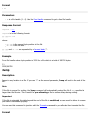
Voltage on any pin
-0.5V to Vcc+0.5V
Maximum Operating Voltage 6.0V
WARNING Exceeding values beyond these absolute maximum values may cause permanent damage to
the device and/or card! Operating at absolute maximum rating conditions for extended periods may
affect device and/or card reliability.
DC Characteristics
Parameter
Power Supply Current
Icc: Idle, Vcc=5V, No card
Icc: Idle, Vcc=3V, No card
Icc: Idle, Vcc=5V, w/card
Min
Typ
Max
Icc: Idle, Vcc=3V, w/card
11 15
5.5 8
12 40+ 1)
6
30+ 2)
Icc: Active (R/W), Vcc=5V
25
Logic Input Low
-0.5
Logic Input High
0.6 Vcc 6)
Logic Output Low @ Vcc=5V
Logic Output Low @ Vcc=3V
Logic Output High @ Vcc=5V 4.0
Logic Output High @ Vcc=3V 2.2
250 3)4)
Units
mA
mA
mA
mA
mA
0.2 Vcc 5) V
V
0.7
V
0.5
V
V
V
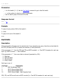
1), 2), 3)
Because card active and idle current values vary widely from brand to brand, a maximum cannot
be determined. Please refer to your card manufacturers specifications for read/write current consumption
values.
4) This is the maximum current that the on-board LDO regulator will supply. Cards that require more power
than this are not supported.
5) “Max” means the highest value where the pin is guaranteed to be read as low.
6) “Min” means the lowest value where the pin is guaranteed to be read as high.
Timing Characteristics
Parameter
Min Typ Max
Units
Serial Speed
2400
460800 bps
Power up delay: no card
200
ms
Power up delay: w/card 200 250 400+ ms
Card initialization time 1) 30 80 200+2) ms
2)
Card communication timing will vary widely from brand to brand depending on many factors.
This is the amount of time taken to initialize a card after insertion and a command has been sent, but
before the command has been executed.
1)
Communications Protocol
Description