1
User’s
Manual
ADMAG AXF Series
FOUNDATION Fieldbus Communication Type
Magnetic Flowmeter
IM01E20F02-01E
IM01E20F02-01E
Yokogawa Electric Corporation
1st Edition
CONTENTS
CONTENTS
1.
INTRODUCTION ............................................................................................ 1-1
Regarding This Manual ................................................................................. 1-1
1.1 Safe Use of This Product .................................................................... 1-2
1.2 Warranty .............................................................................................. 1-3
1.3 Combination Remote Flowtubes ......................................................... 1-3
1.4 ATEX Documentation .......................................................................... 1-4
2.
HANDLING CAUTIONS ................................................................................ 2-1
2.1
3.
Installation of an Explosion-Protected Instrument .............................. 2-1
2.1.1 CENELEC ATEX (KEMA) Certification ........................................ 2-1
2.1.2 FM Approval ................................................................................. 2-3
2.1.3 CSA Certification .......................................................................... 2-4
2.1.4 IECEx Certification ....................................................................... 2-6
2.1.5 TIIS Certification ........................................................................... 2-7
ABOUT FIELDBUS ....................................................................................... 3-1
3.1
3.2
Outline ................................................................................................. 3-1
Internal Structure of AXF .................................................................... 3-1
3.2.1 System/network Management VFD ............................................. 3-1
3.2.2 Function Block VFD ..................................................................... 3-1
3.3 Logical Structure of Each Block .......................................................... 3-1
3.4 Wiring System Configuration .............................................................. 3-2
4.
GETTING STARTED ..................................................................................... 4-1
4.1
4.2
4.3
4.4
4.5
4.6
4.7
5.
Connection of Devices ........................................................................ 4-1
Host Setting ......................................................................................... 4-2
Bus Power ON .................................................................................... 4-3
Integration of DD ................................................................................. 4-3
Reading the Parameters ..................................................................... 4-3
Continuous Record of Values ............................................................. 4-4
Generation of Alarm ............................................................................ 4-4
CONFIGURATION ......................................................................................... 5-1
5.1
5.2
5.3
5.4
5.5
Network Design ................................................................................... 5-1
Network Definition ............................................................................... 5-1
Definition of Combining Function Blocks ............................................ 5-2
Setting of Tags and Addresses .......................................................... 5-3
Communication Setting ....................................................................... 5-4
5.5.1 VCR Setting .................................................................................. 5-4
5.5.2 Function Block Execution Control ................................................ 5-5
5.6 Block Setting ....................................................................................... 5-5
5.6.1 Link Object ................................................................................... 5-5
5.6.2 Trend Object ................................................................................. 5-6
5.6.3 View Object .................................................................................. 5-6
5.6.4 Function Block Parameters ........................................................ 5-11
FD No. IM 01E20F02-01E
1st Edition: June 2006(KP)
All Rights Reserved, Copyright © 2006, Yokogawa Electric Corporation
i
IM 01E20F02-01E
CONTENTS
6.
EXPLANATION OF BASIC ITEMS............................................................... 6-1
6.1
6.2
6.3
6.4
6.5
6.6
7.
Outline ................................................................................................. 6-1
Setting and Changing Parameters for the Whole Process ................ 6-1
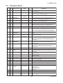
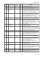
Transducer Block Parameters ............................................................ 6-2
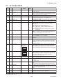
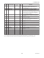
AI Function Block Parameters ............................................................ 6-4
DI Function Block Parameters ............................................................ 6-7
Integral LCD Indicator ......................................................................... 6-8
6.6.1 Flow Data Display ........................................................................ 6-8
6.6.2 Display Modes ............................................................................ 6-10
IN-PROCESS OPERATION .......................................................................... 7-1
7.1
7.2
Mode Transition .................................................................................. 7-1
Generation of Alarm ............................................................................ 7-1
7.2.1 Indication of Alarm ....................................................................... 7-1
7.2.2 Alarms and Events ....................................................................... 7-1
7.3 Simulation Function ............................................................................. 7-2
8.
DEVICE INFORMATION ............................................................................... 8-1
8.1
8.2
9.
DEVICE STATUS ................................................................................ 8-1
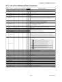
Status of each parameter in failure mode .......................................... 8-4
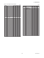
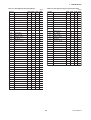
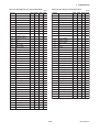
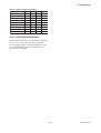
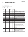
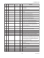
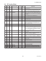
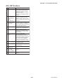
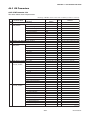
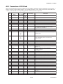
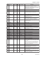
PARAMETER LISTS ..................................................................................... 9-1
9.1
9.2
9.3
9.4
Resource Block ................................................................................... 9-1
Transducer Block ................................................................................ 9-4
AI Function Block ................................................................................ 9-9
Dl Function Block .............................................................................. 9-11
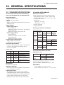
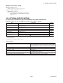
10. GENERAL SPECIFICATIONS .................................................................... 10-1
10.1 STANDARD SPECIFICATIONS ....................................................... 10-1
10.2 OPTIONAL SPECIFICATIONS ......................................................... 10-2
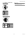
10.3 TERMINAL CONNECTION ............................................................... 10-3
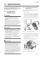
11. MAINTENANCE ........................................................................................... 11-1
11.1 Components Replacement ................................................................ 11-1
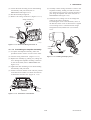
11.1.1 Integral Flowmeter Amplifier Replacement ................................ 11-1
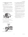
11.1.2 Remote Converter Amplifier Replacement ................................ 11-3
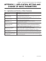
APPENDIX 1. APPLICATION, SETTING AND CHANGE
OF BASIC PARAMETERS ........................................................ A-1
A1.1
A1.2
A1.3
A1.4
A1.5
A1.6
Applications and Selection of Basic Parameters ................................ A-1
Setting and Change of Basic Parameters .......................................... A-2
Setting the AI Function Block ............................................................. A-3
Setting the Transducer Block .............................................................. A-4
Setting the Integrator (IT) Function Block ........................................... A-5
Setting the DI Function Block ............................................................. A-5
ii
IM 01E20F02-01E
CONTENTS
APPENDIX 2. INTEGRATOR (IT) BLOCK ....................................................... A-6
A2.1 Schematic Diagram of Integrator Block .............................................. A-6
A2.2 Input Process Section ......................................................................... A-7
A2.2.1 Determining Input Value Statuses ............................................... A-7
A2.2.2 Converting the Rate ..................................................................... A-7
A2.2.3 Converting Accumulation ............................................................. A-8
A2.2.4 Determining the Input Flow Direction ........................................... A-8
A2.3 Adder ................................................................................................... A-8
A2.3.1 Status of Value after Addition ...................................................... A-8
A2.3.2 Addition ......................................................................................... A-9
A2.4 Integrator ............................................................................................. A-9
A2.5 Output Process ................................................................................. A-11
A2.5.1 Status Determination .................................................................. A-11
A2.5.2 Determining the Output Value .................................................... A-12
A2.5.3 Mode Handling .......................................................................... A-13
A2.6 Reset ................................................................................................. A-13
A2.6.1 Reset Trigger .............................................................................. A-13
A2.6.2 Reset Timing .............................................................................. A-13
A2.6.3 Reset Process ............................................................................ A-14
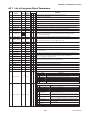
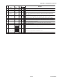
A2.7 List of Integrator Block Parameters .................................................. A-15
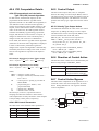
APPENDIX 3. ARITHMETIC (AR) BLOCK ..................................................... A-17
A3.1 Schematic Diagram of Arithmetic Block ........................................... A-17
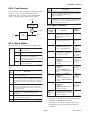
A3.2 Input Section ..................................................................................... A-18
A3.2.1 Main Inputs ................................................................................. A-18
A3.2.2 Auxiliary Inputs ........................................................................... A-18
A3.2.3 INPUT_OPTS ............................................................................. A-19
A3.2.4 Relationship between the Main Inputs and PV .......................... A-19
A3.3 Computation Section ......................................................................... A-20
A3.3.1 Computing Equations ................................................................. A-20
A3.3.2 Compensated Values ................................................................. A-20
A3.3.3 Average Calculation ................................................................... A-20
A3.4 Output Section .................................................................................. A-20
A3.4.1 Mode Handling ........................................................................... A-21
A3.4.2 Status Handling .......................................................................... A-21
A3.5 List of the Arithmetic Block Parameters ........................................... A-22
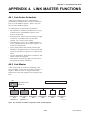
APPENDIX 4. LINK MASTER FUNCTIONS ................................................... A-24
A4.1 Link Active Scheduler ....................................................................... A-24
A4.2 Link Master ........................................................................................ A-24
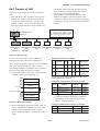
A4.3 Transfer of LAS ................................................................................. A-25
A4.4 LM Functions ..................................................................................... A-26
A4.5 LM Parameters .................................................................................. A-27
A4.5.1 LM Parameter List ...................................................................... A-27
A4.5.2 Descriptions for LM Parameters ................................................ A-29
A4.6 FAQs ................................................................................................. A-31
iii
IM 01E20F02-01E
CONTENTS
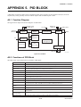
APPENDIX 5. PID BLOCK .............................................................................. A-32
A5.1 Function Diagram .............................................................................. A-32
A5.2 Functions of PID Block ..................................................................... A-32
A5.3 Parameters of PID Block .................................................................. A-33
A5.4 PID Computation Details ................................................................... A-35
A5.4.1 PV-proportional and -derivative Type PID (I-PD) Control
Algorithm .................................................................................... A-35
A5.4.2 PID Control Parameters ............................................................. A-35
A5.5 Control Output ................................................................................... A-35
A5.5.1 Velocity Type Output Action ....................................................... A-35
A5.6 Direction of Control Action ................................................................ A-35
A5.7 Control Action Bypass ....................................................................... A-35
A5.8 Feed-forward ..................................................................................... A-36
A5.9 Block Modes ...................................................................................... A-36
A5.9.1 Mode Transitions ........................................................................ A-36
A5.10 Bumpless Transfer ............................................................................ A-37
A5.11 Setpoint Limiters ............................................................................... A-37
A5.11.1 When PID Block Is in Auto Mode ............................................ A-37
A5.11.2 When PID Block Is in Cas or RCas Mode ............................... A-37
A5.12 External-output Tracking ................................................................... A-37
A5.13 Measured-value Tracking .................................................................. A-37
A5.14 Initialization and Manual Fallback (IMan) ......................................... A-38
A5.15 Manual Fallback ................................................................................ A-38
A5.16 Auto Fallback .................................................................................... A-38
A5.17 Mode Shedding upon Computer Failure ........................................... A-39
A5.17.1 SHED_OPT .............................................................................. A-39
A5.18 Alarms ............................................................................................... A-39
A5.18.1 Block Alarm (BLOCK_ALM) ..................................................... A-39
A5.18.2 Process Alarms ........................................................................ A-39
A5.19 Example of Block Connections ......................................................... A-40
A5.20 View Object for PID Function Block ................................................. A-40
APPENDIX 6. SOFTWARE DOWNLOAD ....................................................... A-42
A6.1
A6.2
A6.3
A6.4
A6.5
A6.6
A6.7
A6.8
A6.9
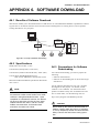
Benefits of Software Download ......................................................... A-42
Specifications .................................................................................... A-42
Preparations for Software Downloading ........................................... A-42
Software Download Sequence .......................................................... A-43
Download Files .................................................................................. A-43
Steps after Activating a Field Device ................................................ A-44
Troubleshooting ................................................................................. A-45
Resource Block’s Parameters Relating to Software Download ....... A-45
System/Network Management VFD Parameters Relating to
Software Download ........................................................................... A-47
A6.10 Comments on System/Network Management VFD Parameters
Relating to Software Download ........................................................ A-48
REVISION RECORD
iv
IM 01E20F02-01E
1. INTRODUCTION
1.
INTRODUCTION
This manual is for the ADMAG AXF Series Magnetic
Flowmeter Remote Converter FOUNDATION fieldbus
Communication Type. The FOUNDATION fieldbus
communication type is based on the same ADMAG
AXF technology used in the BRAIN/HART communication type, and is similar to the communication types
in terms of basic performance and operation. This
manual describes only those topics that are required for
operation of the FOUNDATION fieldbus communication
type. For information on the installation, wiring, and
maintenance of AXF series magnetic flowmeter, refer
to the user’s manual for each model (IM 01E20D0101E or IM 01E20C02-01E).
WARNING
Indicates a potentially hazardous situation which,
if not avoided, could result in death or serious
injury.
CAUTION
Indicates a potentially hazardous situation which,
if not avoided, may result in minor or moderate
injury. It may also be used to alert against
unsafe practices.
As far terminal connection, refer to Page 10-3 of this
manual.
Regarding This Manual
• This manual should be passed on to the end user.
IMPORTANT
• The contents of this manual are subject to change
without prior notice.
Indicates that operating the hardware or software
in this manner may damage it or lead to system
failure.
• All rights reserved. No part of this manual may be
reproduced in any form without Yokogawa’s written
permission.
• Yokogawa makes no warranty of any kind with
regard to this manual, including, but not limited to,
implied warranty of merchantability and fitness for a
particular purpose.
NOTE
Draws attention to information essential for
understanding the operation and features.
• If any question arises or errors are found, or if any
information is missing from this manual, please
inform the nearest Yokogawa sales office.
• The specifications covered by this manual are
limited to those for the standard type under the
specified model number break-down and do not
cover custom-made instruments.
• Please note that changes in the specifications,
construction, or component parts of the instrument
may not immediately be reflected in this manual at
the time of change, provided that postponement of
revisions will not cause difficulty to the user from a
functional or performance standpoint.
FOUNDATION is a registered trademark of Fieldbus
FOUNDATION.
• The following safety symbols are used in this
manual:
1-1
IM 01E20F02-01E
1. INTRODUCTION
1.1
• The protective grounding must be connected
securely at the terminal with the
mark to avoid
danger to personnel.
Safe Use of This Product
For the safety of the operator and to protect the
instrument and the system, please be sure to follow this
manual’s safety instructions when handling this
instrument. If these instructions are not heeded, the
protection provided by this instrument may be impaired. In this case, Yokogawa cannot guarantee that
the instrument can be safely operated. Please pay
special attention to the following points:
(c) Operation
• Do not open the cover until the power has been off
for at least 10 minutes. Only expert engineer or
skilled personnel are permitted to open the cover.
(d) Maintenance
• Please carry out only the maintenance procedures
described in this manual. If you require further
assistance, please contact the nearest Yokogawa
office.
(a) Installation
• Installation of the magnetic flowmeter must be
performed by expert engineer or skilled personnel.
No operator shall be permitted to perform procedures relating to installation.
• Care should be taken to prevent the build up of dust
or other materials on the display glass and the name
plate. To clean these surfaces, use a soft, dry cloth.
• The magnetic flowmeter is a heavy instrument. Be
careful that no damage is caused to personnel
through accidentally dropping it, or by exerting
excessive force on the magnetic flowmeter. When
moving the magnetic flowmeter, always use a trolley
and have at least two people carry it.
(e) Explosion Protected Type Instrument
• Users of explosion proof instruments should refer
first to section 2.1 (Installation of an Explosion
Protected Instrument) of this manual.
• When the magnetic flowmeter is processing hot
fluids, the instrument itself may become extremely
hot. Take sufficient care not to get burnt.
• The use of this instrument is restricted to those who
have received appropriate training in the device.
• Where the fluid being processed is a toxic substance, avoid contact with the fluid and avoid
inhaling any residual gas, even after the instrument
has been taken off the piping line for maintenance
and so forth.
• Take care not to create sparks when accessing the
instrument or peripheral devices in a hazardous
location.
• Do not apply excessive weight, for example, a
person stepping on the magnetic flowmeter.
(f) Modification
• Yokogawa will not be liable for malfunctions or
damage resulting from any modification made to this
instrument by the customer.
• All procedures relating to installation must comply
with the electrical code of the country where it is
used.
(b) Wiring
• The wiring of the magnetic flowmeter must be
performed by expert engineer or skilled personnel.
No operator shall be permitted to perform procedures relating to wiring.
• When connecting the wiring, check that the supply
voltage is within the range of the voltage specified
for this instrument before connecting the power
cable. In addition, check that no voltage is applied
to the power cable before connecting the wiring.
1-2
IM 01E20F02-01E
1. INTRODUCTION
1.2
Warranty
1.3
• The warranty shall cover the period noted on the
quotation presented to the purchaser at the time of
purchase. Problems occurring during the warranty
period shall basically be repaired free of charge.
Combination Remote
Flowtubes
IMPORTANT
• The AXFA14 Magnetic Flowmeter Converter
should be used in combination with the following remote flowtubes:
AXF002-P to AXF400-P
Other flowtubes (size 500 to 2600 mm) cannot
be combined with the AXFA14 converter.
• If any problems are experienced with this instrument, the customer should contact the Yokogawa
representative from which this instrument was
purchased or the nearest Yokogawa office.
• If a problem arises with this instrument, please
inform us of the nature of the problem and the
circumstances under which it developed, including
the model specification and serial number. Any
diagrams, data and other information you can
include in your communication will also be helpful.
CAUTION
In case of combination with the explosion proof
type remote flowtube (AXFC-P) for
CENELEC ATEX, IECEx certification, please see
the manual IM 01E20D01-01E. The construction
of the instrument, installation, external wiring,
maintenance, and repair are strictly restricted,
and non-observance or negligence of these
restriction would result dangerous condition.
• The party responsible for the cost of fixing the
problem shall be determined by Yokogawa following an investigation conducted by Yokogawa.
• The purchaser shall bear the responsibility for repair
costs, even during the warranty period, if the
malfunction is due to:
- Improper and/or inadequate maintenance by the
purchaser.
- Malfunction or damage due to a failure to handle,
use, or store the instrument in accordance with the
design specifications.
- Use of the product in question in a location not
conforming to the standards specified by
Yokogawa, or due to improper maintenance of the
installation location.
- Failure or damage due to modification or repair by
any party except Yokogawa or an approved
representative of Yokogawa.
- Malfunction or damage from improper relocation
of the product in question after delivery.
- Reason of force majeure such as fires, earthquakes,
storms/floods, thunder/lightening, or other natural
disasters, or disturbances, riots, warfare, or
radioactive contamination.
1-3
IM 01E20F02-01E
1. INTRODUCTION
1.4
ATEX Documentation
SF
This procedure is only applicable to the countries in
European Union.
Kaikkien ATEX Ex -tyyppisten tuotteiden käyttöhjeet
ovat saatavilla englannin-, saksan- ja ranskankielisinä.
Mikäli tarvitsette Ex -tyyppisten tuotteiden ohjeita
omalla paikallisella kielellännne, ottakaa yhteyttä
lähimpään Yokogawa-toimistoon tai -edustajaan.
GB
All instruction manuals for ATEX Ex related products
are available in English, German and French. Should
you require Ex related instructions in your local
language, you are to contact your nearest Yokogawa
office or representative.
P
Todos os manuais de instruções referentes aos produtos
Ex da ATEX estão disponíveis em Inglês, Alemão e
Francês. Se necessitar de instruções na sua língua
relacionadas com produtos Ex, deverá entrar em
contacto com a delegação mais próxima ou com um
representante da Yokogawa.
DK
Alle brugervejledninger for produkter relateret til
ATEX Ex er tilgængelige på engelsk, tysk og fransk.
Skulle De ønske yderligere oplysninger om håndtering
af Ex produkter på eget sprog, kan De rette
henvendelse herom til den nærmeste Yokogawa
afdeling eller forhandler.
F
Tous les manuels d’instruction des produits ATEX Ex
sont disponibles en langue anglaise, allemande et
française. Si vous nécessitez des instructions relatives
aux produits Ex dans votre langue, veuillez bien
contacter votre représentant Yokogawa le plus proche.
I
Tutti i manuali operativi di prodotti ATEX
contrassegnati con Ex sono disponibili in inglese,
tedesco e francese. Se si desidera ricevere i manuali
operativi di prodotti Ex in lingua locale, mettersi in
contatto con l’ufficio Yokogawa più vicino o con un
rappresentante.
D
Alle Betriebsanleitungen für ATEX Ex bezogene
Produkte stehen in den Sprachen Englisch, Deutsch
und Französisch zur Verfügung. Sollten Sie die
Betriebsanleitungen für Ex-Produkte in Ihrer
Landessprache benötigen, setzen Sie sich bitte mit
Ihrem örtlichen Yokogawa-Vertreter in Verbindung.
E
Todos los manuales de instrucciones para los
productos antiexplosivos de ATEX están disponibles
en inglés, alemán y francés. Si desea solicitar las
instrucciones de estos artículos antiexplosivos en su
idioma local, deberá ponerse en contacto con la
oficina o el representante de Yokogawa más cercano.
S
Alla instruktionsböcker för ATEX Ex (explosionssäkra)
produkter är tillgängliga på engelska, tyska och
franska. Om Ni behöver instruktioner för dessa
explosionssäkra produkter på annat språk, skall Ni
kontakta närmaste Yokogawakontor eller representant.
NL
Alle handleidingen voor producten die te maken
hebben met ATEX explosiebeveiliging (Ex) zijn
verkrijgbaar in het Engels, Duits en Frans. Neem,
indien u aanwijzingen op het gebied van
explosiebeveiliging nodig hebt in uw eigen taal,
contact op met de dichtstbijzijnde vestiging van
Yokogawa of met een vertegenwoordiger.
GR
ATEX Ex
, .
Ex Yokogawa .
1-4
IM 01E20F02-01E
2.
2.
HANDLING CAUTIONS
HANDLING CAUTIONS
2.1.1
2.1 Installation of an ExplosionProtected Instrument
CENELEC ATEX (KEMA) Certification
WARNING
If a customer makes a repair or modification to an
intrinsically safe or explosionproof instrument and the
instrument is not restored to its original condition, its
intrinsically safe or explosionproof construction may
be compromised and the instrument may be hazardous
to operate. Please contact Yokogawa before making
any repair or modification to an instrument.
Only trained persons use this instrument in
industrial locations.
(1) Technical Data
(Integral Flowmeter)
*AXF002C – AXF400C
Applicable Standard:
EN 50014, EN 50018, EN 50019,
EN 50020, EN 50028, EN 50281-1-1,
EN 60529, EN 61010-1
Certificate: KEMA 03ATEX2435
WARNING
• Magnetic flowmeters with the model name
AXFC and AXFA14C are products which
have been certified as explosion proof type
instruments. Strict limitations are applied to the
structures, installation locations, external wiring
work, maintenance and repairs, etc. of these
instruments. Sufficient care must be taken, as
any violation of the limitations may cause
dangerous situations.
Be sure to read this chapter before handling
the instruments.
For explosion proof type instrument, the description in this chapter is prior to other description in this user's manual.
For TIIS flameproof type instruments, be sure
to read “INSTALLATION AND OPERATING
PRECAUTIONS FOR TIIS FLAMEPROOF
EQUIPMENT” at the end of user’s manual
IM 01E20D01-01E or IM 01E20C02-01E.
CENELEC ATEX (KEMA) Flameproof Type
Group: II
Category: 2G
EEx dme [ia] IIC T6...T3
Electrode Circuit Um: 250 Vac/dc
Maximum power supply voltage: 250 Vac/130 Vdc
Excitation Circuit: 140V max
Enclosure: IP66, IP67
Temperature Class:
Temperature
Class
T6
Maximum Process
Temperature
Minimum Process
Temperature
+70°C (+158°F)
–40°C (–40°F)
T5
+85°C (+185°F)
–40°C (–40°F)
T4
+120°C (+248°F)
–40°C (–40°F)
T3
+130°C (+266°F)
–40°C (–40°F)
T0801.EPS
Ambient Temp.: –40°C to +60°C (–40°F to +140°F)
CENELEC ATEX (KEMA) Type of Protection
“Dust”
Group: II
Category: 1D
Electrode Circuit Um: 250 Vac/dc
Maximum power supply voltage: 250 Vac/130 Vdc
Excitation Circuit: 140V max
Enclosure: IP66, IP67
Maximum surface temperature:
WARNING
The terminal box cover and display cover is
locked by special screw. In case of opening the
cover, please use the hexagonal wrench attached.
The covers of explosion proof type products are
locked. Use the attached hexagonal wrench to
open and close the cover. Before opening the
cover, be sure to check that the power of
flowmeter has been turned off. Once the cover is
closed, be sure to re-lock the product.
Be sure to lock the cover with the special screw
using the hexagonal wrench attached after
tightening the cover.
Maximum Surface
Temperature
Maximum Process
Temperature
T75°C (+167°F)
+70°C (+158°F)
T85°C (+185°F)
+85°C (+185°F)
T100°C (+212°F)
+120°C (+248°F)
T110°C (+230°F)
+130°C (+266°F)
T0802.EPS
Ambient Temp.:–40°C to +60°C (–40°F to +140°F)
2-1
IM 01E20F02-01E
2.
(Remote Converter)
HANDLING CAUTIONS
(3) Installation
Applicable Standard:
EN 50014, EN 50018, EN 50281-1-1,
EN 60529, EN 61010-1
Certificate: KEMA 03ATEX2435
WARNING
• All wiring shall comply with local installation
requirements and local electrical code.
• In hazadous locations, the cable entry devices
shall be of a certified ATEX flameproof type,
suitable for the conditions of use and correctly
installed.
• Unused apertures shall be closed with suitable
flameproof certified blanking elements. (The
plug attached is flameproof certified.)
CENELEC ATEX (KEMA) Flameproof Type
Group: II
Category: 2G
EEx d IIC T6
Maximum power supply voltage: 250 Vac/130 Vdc
Excitation Circuit: 140V max
Enclosure: IP66, IP67
Ambient Temp.: –40°C to +60°C (–40°F to +140°F)
(4) Operation
CENELEC ATEX (KEMA) Type of Protection
“Dust”
Group: II
Category: 1D
Maximum power supply voltage: 250 Vac/130 Vdc
Excitation Circuit: 140V max
Enclosure: IP66, IP67
Maximum surface temperature: T75°C (+167°F)
Ambient Temp.: –40°C to +60°C (–40°F to +140°F)
WARNING
• After de-energizing, delay 20 minutes before
opening.
• Take care not to generate mechanical spark
when access to the instrument and peripheral
devices in hazardous locations.
(2) Electrical Connection
The type of electrical connection is stamped near the
electrical connection port according to the following
codes.
(5) Maintenance and Repair
WARNING
The instrument modification or parts replacement
by other than authorized representative of
Yokogawa Electric Corporation is prohibited and
will void the certification.
(Integral Flowmeter)
Screw Size
ISO M20x1.5 female
ANSI 1/2NPT female
Marking
M
A
(6) Data Plate
(Integral Flowmeter)
VDC
mm
12W
50/60Hz 30VA 12W
mA (0-750 Ω)
H
VDC 0.2A MAX.
MPa MAX.
(Remote Converter)
Screw Size
ISO M20x1.5 female
ANSI 1/2NPT female
VAC
L
F0801.EPS
˚C
˚C
Marking
M
A
*2) 0344
*4) 0038
2G
1D
Made in
No.: KEMA03ATEX2435
EEx dme [ia] C T6...T3
ENCLOSURE: IP66, IP67
ELECTRODE CIRCUIT Um: 250Vac/dc
*3)
Tamb: –40 TO +60 °C
TEMP. CLASS
T6 T5 T4
T3
WARNING
User’s Manual
MAX.PROCESS TEMP.(˚C) +70 +85 +120 +130
MAX. SURFACE TEMP. T75°C T85°C T100°C T110°C
FOR DUST-PROOF
TOKYO 180-8750 JAPAN
MODEL: Specified model code
SUFFIX: Suffix codes of the model code
STYLE: Specified style code
SIZE: Nominal size of apparatus
METER FACTOR: Sensor constant number of apparatus
SUPPLY: Power supply voltage of apparatus
OUTPUT: Output signal of apparatus
FLUID TEMP.: Fluid temperature of apparatus
FLUID PRESS: Fluid pressure of apparatus
AMB. TEMP., Tamb: Ambient temperature
No.: Manufacturing serial number *1)
CE: CE marking
II 2G: Group II Category 2 Gas atmosphere
II 1D: Group II Category 1 Dust atmosphere
F1201.EPS
2-2
IM 01E20F02-01E
2.
2.1.2
No.: KEMA 03ATEX2435:
EC Type Examination certificate number
EEx dme[ia]IIC T6...T3: Protection type and temp. class
ELECTRODE CIRCUIT Um: Voltage of electrode circuit
ENCLOSURE: Enclosure protection code
(Integral Flowmeter)
*AXF002C – AXF400C
Applicable Standard:
FM3600, FM3610, FM3615,
FM3810, ANSI/NEMA 250
Explosion proof for Class I, Division 1, Groups A,
B, C & D.
Dust-ignition proof for Class II/III, Division1,
Groups E, F & G.
Intrinsically safe (electrodes) for Class I, Division 1,
Groups A, B, C & D.
“SEAL ALL CONDUITS WITHIN 18 INCHES”
“WHEN INSTALLED IN DIV. 2, SEALS NOT
REQUIRED”
*1) The third figure from the last shows the last one
figure of the year of production. For example, the
year of production of the product engraved as
follows is year 2003.
No. F261GA091 313
↑
Produced in 2003
*2) The identification number of the notified body :
0344 KEMA Netherland
*3) The product-producing country
*4) In case of the sizes of 2.5 to 25mm (0.1 to 1.0
in.) , “0038” is not described.
Electrode Circuit Um: 250 Vac/dc
Maximum power supply voltage: 250 Vac/130 Vdc
Excitation Circuit: 140V max
Enclosure: NEMA 4X
Temperature Code: T6
Refer to following table;
(Remote Converter)
mA (0-750 Ω)
VDC 0.2A MAX.
MODEL
AMB.TEMP.
SUFFIX
˚C
TAG NO.
NO.
STYLE
COMB.NO.
SUPPLY
VAC
0344
*2)
VDC 12W
50/60Hz 30VA 12W
2G
1D
Temperature
Code
No.: KEMA 03ATEX2435
EEx d C T6
ENCLOSURE: IP66, IP67
Tamb: –40 TO +60 °C
MAX.SURFACE TEMP.: T75°C
FOR DUST-PROOF
WARNING
Made in
FM Approval
(1) Technical Data
WARNING: Warning to apparatus
YOKOGAWA TOKYO 180-8750 JAPAN :
Name and address of manufacturer
OUTPUT
HANDLING CAUTIONS
T6
User’s Manual
*3)
TOKYO 180-8750 JAPAN
Maximum Process
Temperature
Minimum Process
Temperature
+70°C (+158°F)
–40°C (–40°F)
T5
+85°C (+185°F)
–40°C (–40°F)
T4
+120°C (+248°F)
–40°C (–40°F)
T3
+130°C (+266°F)
–40°C (–40°F)
T27-1.EPS
MODEL: Specified model code
SUFFIX: Suffix codes of the model code
STYLE: Specified style code
SUPPLY: Power supply voltage of apparatus
OUTPUT: Output signal of apparatus
AMB. TEMP., Tamb: Ambient temperature
No.: Manufacturing serial number *1)
Ambient Temp.: –40°C to +60°C (–40°F to +140°F)
(Remote Converter)
Ambient Temp.: –40°C to +60°C (–40°F to +140°F)
Applicable Standard:
FM3600, FM3615, FM3810, ANSI/NEMA 250
Explosion proof for Class I, Division 1, Groups A,
B, C & D.
Dust-ignition proof for Class II/III, Division 1,
Groups E, F & G.
“SEAL ALL CONDUITS WITHIN 18 INCHES”
“WHEN INSTALLED IN DIV. 2, SEALS NOT
REQUIRED”
CE: CE marking
II 2G: Group II Category 2 Gas atmosphere
II 1D: Group II Category 1 Dust atmosphere
No.: KEMA 03ATEX2435:
EC Type Examination certificate number
EEx d IIC T6: Protection type and temp. class
ENCLOSURE: Enclosure protection code
WARNING: Warning to apparatus
YOKOGAWA TOKYO 180-8750 JAPAN :
Name and address of manufacturer
Maximum power supply voltage: 250 Vac/130 Vdc
Excitation Circuit: 140V max
Enclosure: NEMA 4X
Temperature Code: T6
Ambient Temp.: –40°C to +60°C (–40°F to +140°F)
*1) The third figure from the last shows the last one
figure of the year of production. For example, the
year of production of the product engraved as
follows is year 2003.
No. F261GA091 313
↑
Produced in 2003
*2) The identification number of the notified body:
0344 KEMA Netherland
*3) The product-producing country
2-3
IM 01E20F02-01E
2.
2.1.3
(2) Installation
HANDLING CAUTIONS
CSA Certification
(1) Technical Data
WARNING
(Integral Flowmeter)
*AXF002C – AXF400C
Applicable Standard:
For CSA C22.2 Series;
C22.2 No 0, C22.2 No 0.4, C22.2 No 0.5,
C22.2 No 25, C22.2 No 30, C22.2 No 94,
C22.2 No 157, C22.2 No 1010.1
For CSA E79 Series;
CAN/CSA-E79-0, CAN/CSA-E79-1,
CAN/CSA-E79-7, CAN/CSA-E79-11,
CAN/CSA-E79-18
Certificate: 1481213
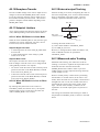
• All wiring shall comply with National Electrical
Code ANSI/NFPA 70 and Local Electrical
Code.
• In hazardous locations, wiring to be in conduit
as shown in Figure 8.2.1.
• When installed in Division 2, “SEALS NOT
REQUIRED”
(3) Operation
For CSA C22. 2 Series
Explosion proof for Class I, Division 1, Groups A,
B, C & D.
Dust-ignition proof for Class II/III, Division 1,
Groups E, F & G.
Intrinsically safe (electrodes) for Class I, Division 1,
Groups A, B, C & D.
“SEAL ALL CONDUITS WITHIN 50 cm OF THE
ENCLOSURE”
“WHEN INSTALLED IN DIV. 2, SEALS NOT
REQUIRED”
WARNING
• “OPEN CIRCUIT BEFORE REMOVING COVERS.”
• “SEALS ALL CONDUITS WITHIN 18 INCHES”
in hazardous locations.
• When installed in Division 2, “SEALS NOT
REQUIRED”
• Take care not to generate mechanical spark
when access to the instrument and peripheral
devices in hazardous locations.
Electrode Circuit Um: 250 Vac/dc
Maximum power supply voltage: 250 Vac/130 Vdc
Excitation Circuit: 140V max
Enclosure: Type 4X
Temperature Code:
(4) Maintenance and Repair
WARNING
The instrument modification or parts replacement
by other than authorized representative of
Yokogawa Electric Corporation is prohibited and
will void the approval of Factory Mutual Research Corporation.
Temperature
Code
Maximum Process
Temperature
Minimum Process
Temperature
T6
+70°C (+158°F)
–40°C (–40°F)
T5
+85°C (+185°F)
–40°C (–40°F)
T4
+120°C (+248°F)
–40°C (–40°F)
T3
+130°C (+266°F)
–40°C (–40°F)
T27-1.EPS
HAZARDOUS LOCATIONS
Conduit
Ambient Temp.: –40°C to +60°C (–40°F to +140°F)
Sealing Fitting
For CSA E79 Series
Flameproof for Zone 1, Ex dme [ia] IIC T6...T3
Intrinsically safe (electrodes), Ex ia IIC T6...T3
Magnetic Flowmeter
Electrode Circuit Um: 250 Vac/dc
Maximum power supply voltage: 250 Vac/130 Vdc
Excitation Circuit: 140V max
Enclosure: IP66, IP67
Temperature Code:
18" (457 mm) Max.
F1202.EPS
Figure 2.1.2.1 Conduit Wiring
Temperature
Code
Maximum Process
Temperature
Minimum Process
Temperature
T6
+70°C (+158°F)
–40°C (–40°F)
T5
+85°C (+185°F)
–40°C (–40°F)
T4
+120°C (+248°F)
–40°C (–40°F)
T3
+130°C (+266°F)
–40°C (–40°F)
T0807.EPS
Ambient Temp.: –40°C to +60°C (–40°F to +140°F)
2-4
IM 01E20F02-01E
2.
(Remote Converter)
HANDLING CAUTIONS
• In hazadous locations, the cable entry devices
shall be of a certified flameproof type, suitable
for the conditions of use and correctly installed.
• Unused apertures shall be closed with suitable
flameproof certified blanking elements. (The
plug attached is flameproof certified.)
Applicable Standard:
For CSA C22.2 Series;
C22.2 No 0, C22.2 No 0.4, C22.2 No 0.5,
C22.2 No 25, C22.2 No 30, C22.2 No 94,
C22.2 No 1010.1
For CSA E79 Series;
CAN/CSA-E79-0, CAN/CSA-E79-1,
Certificate: 1481213
(3) Operation
For CSA C22.2 Series
For CSA C22.2 Series
Explosion proof for Class I, Division 1, Groups A,
B, C & D.
Dust-ignition proof for Class II/III, Division 1,
Groups E, F & G.
“SEAL ALL CONDUITS WITHIN 50 cm OF THE
ENCLOSURE”
“WHEN INSTALLED IN DIV. 2, SEALS NOT
REQUIRED”
WARNING
WARNING : OPEN CIRCUIT BEFORE REMOVING COVER.
OUVRIR LE CIRCUIT AVANT
D’ENLEVER LE COUVERCLE.
• Take care not to generate mechanical spark
when access to the instrument and peripheral
devices in hazardous location.
Maximum power supply voltage: 250 Vac/130 Vdc
Excitation Circuit: 140V max
Enclosure: Type 4X
Temperature Code: T6
Ambient Temp.: –40°C to +60°C (–40°F to +140°F)
For CSA E79 Series
WARNING
WARNING : AFTER DE-ENERGIZING, DELAY
20 MINUTES BEFORE OPENING.
APRÉS POWER-OFF, ATTENDRE
20 MINUTES AVANT D’OUVRIR.
• Take care not to generate mechanical spark
when access to the instrument and peripheral
devices in hazardous locations.
For CSA E79 Series
Flameproof for Zone 1, Ex d IIC T6
Maximum power supply voltage: 250 Vac/130 Vdc
Excitation Circuit: 140V max
Enclosure: IP66, IP67
Temperature Code: T6
Ambient Temp.: –40°C to +60°C (–40°F to +140°F)
(2) Installation
(4) Maintenance and Repair
For CSA C22.2 Series
WARNING
WARNING
The instrument modification or parts replacement
by other than authorized representative of
YOKOGAWA Electric Corporation or
YOKOGAWA Corporation of AMERICA is
prohibited and will void Canadian Standards
Explosionproof Certification.
• All wiring shall comply with Canadian Electrical
Code Part I and Local Electrical Codes.
• In hazardous location, wiring shall be in conduit
as shown in Figure 8.3.1.
WARNING : SEAL ALL CONDUITS WITHIN
50cm OF THE ENCLOSURE’.
UN SCELLEMENT DOIT ÉTRE
INSTALLÉ À MOINS DE 50cm DU
BOÎTIER.
• When installed in Division 2, “SEALS NOT
REQUIRED”
HAZARDOUS LOCATIONS
Conduit
Sealing Fitting
Magnetic Flowmeter
For CSA E79 Series
50 cm Max.
WARNING
F0803.EPS
Figure 2.1.3.1 Conduit Wiring
• All wiring shall comply with local installation
requirements and local electrical code.
2-5
IM 01E20F02-01E
2.
2.1.4
IECEx Certification
HANDLING CAUTIONS
(Remote Converter)
Applicable Standard:
IEC60079-0: 2004, IEC60079-1: 2003,
IEC61241-0: 2004, IEC61241-1: 2004,
IEC60529: 1999 + Edition 2.1: 2001
Certificate: IECEx KEM 05.0018
WARNING
Only trained persons use this instrument in
industrial locations.
IECEx Flameproof Type
Ex d IIC T6
Maximum power supply voltage: 250 Vac/130 Vdc
Enclosure: IP66, IP67
Ambient Temp.: –40°C to +60°C (–40°F to +140°F)
(1) Technical Data
(Integral Flowmeter)
*AXF002C – AXF400C
Applicable Standard:
IEC60079-0: 2004, IEC60079-1: 2003,
IEC60079-7: 2001, IEC60079-11: 1999,
IEC60079-18: 2004,
IEC61241-0: 2004, IEC61241-1: 2004,
IEC60529: 1999 + Edition 2.1: 2001
Certificate: IECEx KEM 05.0018
IECEx Type of Protection “Dust”
Ex tD A21 IP6x T95°C
Maximum power supply voltage: 250 Vac/130 Vdc
Excitation Circuit: 140V max
Enclosure: IP66, IP67
Maximum surface temperature: T95°C (+203°F)
Ambient Temp.: –40°C to +60°C (–40°F to +140°F)
IECEx Flameproof Type
Ex demb[ia] IIC T6...T3
Electrode Circuit Um: 250 Vac/dc
Maximum power supply voltage: 250 Vac/130 Vdc
Excitation Circuit: 140V max
Enclosure: IP66, IP67
Temperature Class:
Temperature
Class
Process Temperature
T6
–40°C to +70°C (–40°F to +158°F)
T5
–40°C to +85°C (–40°F to +185°F)
T4
–40°C to +120°C (–40°F to +248°F)
T3
–40°C to +130°C (–40°F to +266°F)
(2) Installation
WARNING
• All wiring shall comply with local installation
requirements and local electrical code.
• In hazardous locations, the cable entry devices
shall be of a certified IECEx flameproof type,
suitable for the conditions of use and correctly
installed.
• Unused apertures shall be closed with suitable
flameproof certified blanking elements. (The
plug attached is certified as the flameproof and
IP66 or IP67 as a part of this apparatus.)
• In case of ANSI 1/2 NPT plug, ANSI hexagonal
wrench should be applied to screw in.
T0809.EPS
Ambient Temp.:
PFA Lining; –40˚C to +60˚C (–40˚F to +140˚F)
Ceramics Lining; –15˚C to +60˚C (+5˚F to +140˚F)
IECEx Type of Protection "Dust"
Ex tD A21 IP6x T95˚C, T105˚C, T120˚C, T130˚C
Electrode Circuit Um: 250 Vac/dc
Maximum power supply voltage: 250 Vac/130 Vdc
Excitation Circuit: 140V max
Enclosure: IP66, IP67
Maximum surface temperature:
Maximum Surface
Temperature
Process Temperature
T95°C (+203°F)
–40°C to +70°C (–40°F to +158°F)
T105°C (+221°F)
–40°C to +85°C (–40°F to +185°F)
T120°C (+248°F)
–40°C to +120°C (–40°F to +248°F)
T130°C (+266°F)
–40°C to +130°C (–40°F to +266°F)
(3) Operation
WARNING
• After de-energizing, delay 20 minutes before
opening.
• Take care not to generate mechanical spark
when access to the instrument and peripheral
devices in hazardous locations.
(4) Maintenance and Repair
WARNING
T0810.EPS
Ambient Temp.:
PFA Lining; –40˚C to +60˚C (–40˚F to +140˚F)
Ceramics Lining; –15˚C to +60˚C (+5˚F to +140˚F)
The instrument modification or parts replacement
by other than authorized representative of
Yokogawa Electric Corporation is prohibited and
will void the certification.
2-6
IM 01E20F02-01E
2.
2.1.5
TIIS Certification
CAUTION
•
•
The model AXFC magnetic flowmeter and
AXFA14C magnetic flowmeter remote converter
with optional code JF3, which has obtained
certification according to technical criteria for
explosion-protected construction of electric
machinery and equipment (Standards
Notification No. 556 from the Japanese Ministry
of Labor) conforming to IEC standards, is
designed for hazardous areas where
inflammable gases or vapors may be present.
(This allows installation in Division 1 and 2
areas)
To preserve the safety of flameproof equipment
requires great care during mounting, wiring, and
piping. Safety requirements also place
restrictions on maintenance and repair activities.
Users absolutely must read “INSTALLATION
AND OPERATING PRECAUTIONS FOR TIIS
FLAMEPROOF EQUIPMENT” at the end of
user’s manual IM 01E20D01-01E or
IM 01E20C02-01E.
•
•
•
•
HANDLING CAUTIONS
Um=250VAC 50/60Hz, 250VDC,
Uo=250V*, Io=3.37mA*, Po=0.211W
*Uo and Io are rms value.
Ignition and Explosion Class of gas or vapour: IIC T4
Ambient Temperature: –20 to 60°C (power supply code 1)
: –20 to 50°C (power supply code 2)
Fluid Temperature: 120°C max
Electrode Circuit: 250 V AC/DC
Maximum power supply voltage: 250V AC/130V DC
Grounding: JIS Class C(grouding resistance 10Ω or
less) or JIS Class A(grounding resistance 10Ω
or less)
(Remote Converter)
• Certificate: C16678
• Construction: Ex d IIC T6
: Explosion proof
• Ignition and Explosion Class of gas or vapour: IIC T6
• Ambient Temperature: –20 to 60°C (power supply code 1)
: –20 to 50°C (power supply code 2)
• Maximum power supply voltage: 250V AC/130V DC
• Grounding: JIS Class C(grouding resistance 10 or
less) or JIS Class A(grounding resistance 10
or less)
WARNING
In case that ambient temperature exceeds 50°C,
use heat-resistant cables with maximum allowable temperature of 70°C or above.
(1) Technical Data
(Integral Flowmeter)
WARNING
Certificate:
Lining
Integral Flowmeter
PFA
Lining
Ceramics
Lining
2.5 (0.1)
C16630
C16645
5 (0.2)
C16630
C16645
10 (0.4)
C16630
C16645
15 (0.5)
C16630
C16646
25 (1.0)
C16631
C16647
32 (1.25)
C16632
—
40 (1.5)
C16633
C16648
50 (2.0)
C16634
C16649
65 (2.5)
C16635
—
Size: mm
(inch)
80 (3.0)
C16636
C16650
100 (4.0)
C16637
C16651
125 (5.0)
C16638
—
150 (6.0)
C16639
C16652
200 (8.0)
C16640
C16653
250 (10)
C16641
—
300 (12)
C16642
—
350 (14)
C16643
—
400 (16)
C16644
—
* In case of TIIS Flameproof type, a remote
flowtube is available for combined use with the
AXFA14 only.
(2) Wiring Installation
For the external wiring of flameproof types, use a
flameproof packing adapter approved by Yokogawa
(refer to Figure 2.1.5.1) or cable wiring using a
flameproof metal conduit (refer to Figure 2.1.5.4 and
“INSTALLATION AND OPERATING PRECAUTIONS FOR TIIS FLAMEPROOF EQUIPMENT” at
the end of user’s manual IM 01E20D01-01E or
IM 01E20C02-01E.).
T33.EPS
• Construction: Ex de[ia] IIC T4
: Converter ; Explosion proof
Flowtube ; Increased Safety and
Intrinsically Safety(ia)
Electrode ; Intrinsically Safety(ia)
2-7
IM 01E20F02-01E
2.
(2-1) Wiring Cable through Flameproof Packing Adapter
CAUTION
Before fighting, confirm cable length from
terminal to flameproof packing adapter when
setting. Once it is tightened, loosening and retightening may damage its sealing performance.
WARNING
For the TIIS flameproof type with wiring using a
flameproof packing adapter, wire cables through
the packing adapters approved by Yokogawa
(optional code G12 or G14).
16.5(0.65)
18(0.71)
L
F
G
*Packing
(Choose from the table below
depend on cable outside diameter) T2
(a) Loosen the locking screw and remove the terminal
box cover.
(b) Measure the cable outer diameter in two directions
to within 0.1 mm.
(c) Calculate the average of the two diameters, and use
packing with an internal diameter nearest to this
value (see Figure 2.1.5.1).
(d) Screw the flameproof packing adapter into the
terminal box until the O-ring touches the wiring
port (at least 6 full turns), and firmly tighten the
lock nut.
(e) Insert the cable through the union cover, the union
coupling, the clamp nut, the clamp ring, the gland,
the washer, the rubber packing, and the packing
box, in that order.
(f) Insert the end of the cable into the terminal box.
(g) Tighten the union cover to grip the cable. When
tightening the union cover, tighten approximately
one turn past the point where the cable will no
longer move up and down.
Proper tightening is important. If it is too tight, a
circuit break in the cable may occur; if not tight
enough, the flameproof effectiveness will be
compromised.
(h) Fasten the cable by tightening the clamp nut.
(i) Tighten the lock nut on the union cover.
(j) Connect the cable wires to each terminal.
Unit : mm
(Approx. inch)
T1
Adapter body(M. Screw)
O-Ring
Packing case
Hexagon socket set screw
Packing *
Hexagon socket set screw
O-Ring
C
O-Ring
Washer
Union nut
Packing gland
Clamp ring
Clamp nut
O-Ring
B.coupling
Cable(user's scope)
D
Dimension
Packing diameter Identification Weight
kg
mark
F
G
(lb)
39 94.5 8.0 to 10.0 (0.31 to 0.39) 10.0(0.39) 20.0 16 8-10 0.26
G 1/2 G 1/2 35
(1.38) (1.54) (3.72) 10.0 to 12.0 (0.39 to 0.47) 12.0(0.47) (0.79) 16 10-12 (0.57)
T1
T2
C
D
L
Cable outer diameter
F0809.EPS
Figure 2.1.5.1 Flameproof Packing Adapter
• Apply a nonhardening sealant to the terminal box
connection port and to the threads on the flameproof
packing adapter for waterproofing.
• The same wiring as described below is required for
all of the terminal box connection ports.
Flameproof
packing adapter
Flexible metal conduit
Wiring metal
conduit
Tee
HANDLING CAUTIONS
Wrench
Lock nut
Union coupling
Clamp nut
Clamp ring
Apply a non-hardening
sealant to the threads
for waterproofing.
Gland
Washer
Cable
Drain plug
Rubber packing
Wrench
Union cover
Lock nut
F0810.EPS
Figure 2.1.5.2 Typical Wiring Using Flexible Metal Conduit
Packing box
Adapter body
Follow the procedure for flameproof packing adapter
setting. (refer to Figure 2.1.5.3)
O-ring
Apply a nonhardnening sealant to
the threads for
waterproofing.
F0811.EPS
Figure 2.1.5.3 Installing Flameproof Packing Adapter
2-8
IM 01E20F02-01E
2.
HANDLING CAUTIONS
(2-2) Cable Wiring Using Flameproof Metal
Conduit
• A seal fitting must be installed near the terminal box
connection port for a sealed construction.
• Apply a non-hardening sealant to the threads of the
terminal box connection port, flexible metal conduit
and seal fitting for waterproofing.
• The same wiring as described below is required for
all of the terminal box connection ports.
Non-hazardous
area
Hazardous area
Flameproof
heavy-gauge
steel conduit
Tee
Drain plug
Flameproof flrxible
metal conduit
Gas sealing
device
Apply a non-hardening
sealant to the threads
of these fittings for
waterproofing
Seal fitting
After wrining, impregnate the
fitting with a compound to seal tubing.
F0812.EPS
Figure 2.1.5.4 Typical Wiring Using Flameproof Metal
Conduit
2-9
IM 01E20F02-01E
3. ABOUT FIELDBUS
3.
ABOUT FIELDBUS
3.1 Outline
Fieldbus is a widely used bi-directional digital communication protocol for field devices that enable the simultaneous output to many types of data to the process
control system.
The AXF Series Fieldbus communication type employs
the specification standardized by The Fieldbus Foundation, and provides interoperability between Yokogawa
devices and those produced by other manufacturers.
Fieldbus comes with software consisting of AI, DI, IT,
AR and optional PID function blocks that enable the
flexible implementation of systems.
For information on other features, engineering, design,
construction work, startup and maintenance of
Fieldbus, refer to “Fieldbus Technical Information” (TI
38K03A01-01E).
(4)DI function blocks (two)
• Limit switches for the flow rate and adhesion alarm,
warning.
(5)IT function blocks (two)
• Add two main inputs and integrate them for output.
(6)AR function block
• Switches two main inputs of different measurement
ranges and combines the result with three auxiliary
inputs through the selected compensation function to
calculate the output.
(7)PID function block (optional)
• Performs the PID control computation based on the
deviation of the measured value from the setpoint.
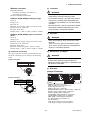
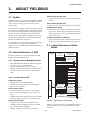
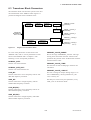
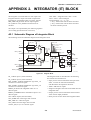
3.3 Logical Structure of Each
Block
3.2 Internal Structure of AXF
AXF
Fieldbus
The AXF contains two Virtual Field Devices (VFD)
that share the following functions.
System/network management VFD
PD Tag
Communication
parameters
Node address
VCR
Function block
execution schedule
3.2.1 System/network Management VFD
Link Master
• Sets node addresses and Physical Device tags (PD
Tag) necessary for communication.
• Controls the execution of function blocks.
• Manages operation parameters and communication
resources (Virtual Communication Relationship:
VCR).
Function block VFD
PID function
block (option)
AR function
block
IT function
block
IT function
block
3.2.2 Function Block VFD
AI function
block
(1)Resource block
• Manages the status of AXF hardware.
• Automatically informs the host of any detected
faults or other problems.
Sensor
DI function
block
(2)Transducer block
• Converts the flow sensor output to the volumetric
flow rate signal, and transfers to the AI function
block.
• Transfers limit switch signals to DI function blocks.
• Adhesion diagnosis levels are set and monitored.
(3)AI function blocks
• Condition raw data from the transducer block,
including scaling and damping (with a first-order
lag), and allow input simulation.
• Outputs volumetric or mass flow rate signals.
Sensor
input
SENSOR
Transducer block
DI function
block
Block tag
Block tag
Parameters
Parameters
Output
OUT_D
Resource block
Block tag
Parameters
F0301.EPS
Figure 3.1 Logical Structure of Each Block
Setting of various parameters, node addresses, and PD
Tags shown in Figure 3.1 is required before starting
operation.
3-1
IM 01E20F02-01E
3. ABOUT FIELDBUS
3.4 Wiring System Configuration
The number of devices that can be connected to a
single bus and the cable length vary depending on
system design. When constructing systems, both the
basic and overall design must be carefully considered
to achieve optimal performance.
3-2
IM 01E20F02-01E
4. GETTING STARTED
4.
GETTING STARTED
Fieldbus is fully dependent upon digital communication protocol and differs in operation from conventional 4 to 20 mA transmission and the BRAIN
communication protocol. It is recommended that
novice users use field devices in accordance with the
procedures described in this section. The procedures
assume that field devices will be set up on a bench or
in an instrument shop.
Refer to Yokogawa when making arrangements to
purchase the recommended equipment.
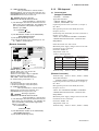
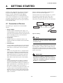
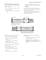
Connect the devices as shown in Figure 4.1. Connect
the terminators at both ends of the trunk, with a
minimum length of the spur laid for connection.
The polarity of signal and power must be maintained.
Fieldbus power
supply
4.1 Connection of Devices
The following are required for use with Fieldbus
devices:
• Power supply:
Fieldbus requires a dedicated power supply. It is
recommended that current capacity be well over the
total value of the maximum current consumed by all
devices (including the host). Conventional DC
current cannot be used as is.
• Host:
Used for accessing field devices. A dedicated host
(such as DCS) is used for an instrumentation line
while dedicated communication tools are used for
experimental purposes. For operation of the host,
refer to the instruction manual for each host. No
other details on the host are given in this manual.
HOST
Terminator
Terminator
F0401.EPS
Figure 4.1 Cabling
NOTE
• Terminator:
Fieldbus requires two terminators. Refer to the
supplier for details of terminators that are attached
to the host.
• Field devices:
Connect Fieldbus communication type AXF (Refer
to section 10.3 terminal connection). Two or more
AXF devices or other devices can be connected.
AXF
No CHECK terminal is used for Fieldbus communication AXF. Do not connect the field indicator
and check meter.
Before using a Fieldbus configuration tool other than
the existing host, confirm it does not affect the loop
functionality in which all devices are already installed
in operation. Disconnect the relevant control loop from
the bus if necessary.
IMPORTANT
Connecting a Fieldbus configuration tool to a
loop with its existing host may cause communication data scrambling resulting in a functional
disorder or a system failure.
• Cable:
Used for connecting devices. Refer to “Fieldbus
Technical Information” (TI 38K03A01-01E) for
details of instrumentation cabling. For laboratory or
other experimental use, a twisted pair cable two to
three meters in length with a cross section of
0.9 mm2 or more and a cycle period of within 5 cm
(2 inches) may be used. Termination processing
depends on the type of device being deployed. For
AXF, use an M4 screw terminal claw. Some hosts
require a connector.
4-1
IM 01E20F02-01E
4. GETTING STARTED
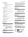
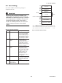
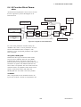
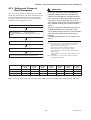
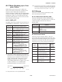
4.2 Host Setting
0x00
To activate Fieldbus, the following settings are
required for the host.
0x0F
0x10
Not used
0x13
0x14
Bridge device
LM device
V(FUN)
IMPORTANT
Unused
Do not turn off the power immediately after
setting. When the parameters are saved to the
EEPROM, the redundant processing is executed
for an improvement of reliability. If the power is
turned off within 60 seconds after setting is
made, the modified parameters are not saved
and the settings may return to the original
values.
V(FUN)V(NUN)
V(NUN)
BASIC device
0xF7
0xF8
Default address
0xFB
0xFC
Portable device address
0xFF
Note 1: Bridge device: A linking device which brings data from one
or more H1 networks.
Note 2: LM device: with bus control function (Link Master function)
Note 3: BASIC device: without bus control function
F0402.EPS
Table 4.1 Operation Parameters
Symbol
Parameter
Figure 4.2 Available Address Range
Description and Settings
V (ST)
Slot-Time
Indicates the time
necessary for immediate
reply of the device. Unit of
time is in octets (256 µs).
Set maximum specification
for all devices. For AXF,
set a value of 4 or greater.
V (MID)
Minimum-Inter-PDUDelay
Minimum value of
communication data
intervals. Unit of time is in
octets (256 µs). Set the
maximum specification for
all devices. For AXF, set a
value of 4 or greater.
V (MRD) Maximum-ReplyDelay
The worst case time
elapsed until a reply is
recorded. The unit is Slottime; set the value so that
V (MRD) V (ST) is the
maximum value of the
specification for all
devices. For AXF, the
setting must be a value of
12 or greater.
V (FUN) First-Unpolled-Node
Indicate the address next
to the address range used
by the host. Set 015 or
greater.
V (NUN) Number-ofconsecutiveUnpolled-Node
Unused address range.
T0401.EPS
4-2
IM 01E20F02-01E
4. GETTING STARTED
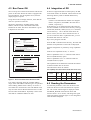
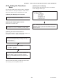
4.3 Bus Power ON
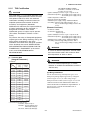
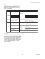
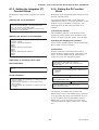
4.4 Integration of DD
Turn on the power of the host and the bus and also the
power for the AXF. Where the AXF is equipped with
an LCD indicator, first all segments are lit, then the
display begins to operate.
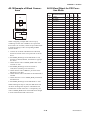
If the host supports DD (Device Description), the DD
of the AXF needs to be installed. Check if host has the
following directory under its default DD directory.
Using the host device display function, check that the
AXF is in operation on the bus.
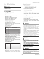
The device information, including PD tag, Node
address, and Device ID, is described on the sheet
attached to the AXF. The device information is given
in duplicate on this sheet.
DEVICE INFORMATION
Device ID
PD Tag
Device Revision
Node Address
Serial No.
Physical Location
:
:
:
:
:
:
594543000BXXXXXXXX
FT2001
1
0xF4
XXXXXXXXXXXXXXXXX
594543\000B
(594543 is the manufacturer number of Yokogawa
Electric Corporation, and 000B is the AXF device
number, respectively.)
If this directory is not found, the DD of the AXF has
not been included. Create the above directory and copy
the DD file (0m0n.ffo, 0m0n.sym) (m, n is a numeral)
into the directory. ‘0m’ in the file name shows the
device revision, and ‘0n’ shows the DD revision. If
you do not have the DD or capabilities files, you can
download them from our web site:
http://www.yokogawa.com/fld
Once the DD is installed in the directory, the name and
attribute of all parameters of the AXF are displayed.
Note:
Off-line configuration is possible by using capabilities
files.
Our Device Description Files and Capabilities Files available at
http://www.yokogawa.com/fld (English) or
http://www.yokogawa.co.jp/Sensor/fieldbus/fieldbus.htm (Japanese)
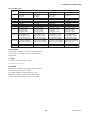
AXF has two capabilities levels, “1” and “2”.
Select “Capabilities level = 1” when the AXF doesn’t
have LC1(PID function) option.
DEVICE INFORMATION
Device ID
PD Tag
Device Revision
Node Address
Serial No.
Physical Location
:
:
:
:
:
:
Select “Capabilities level = 2” when the AXF has
LC1(PID function) option.
594543000BXXXXXXXX
FT2001
1
0xF4
XXXXXXXXXXXXXXXXX
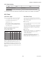
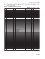
The capabilities level defines the kind and the number
of function blocks that can be used.
The table below shows the relation.
Note:
Our Device Description Files and Capabilities Files available at
http://www.yokogawa.com/fld (English) or
http://www.yokogawa.co.jp/Sensor/fieldbus/fieldbus.htm (Japanese)
The capability level and function blocks that can be used
F0403.EPS
Figure 4.3 Device Information Sheet Attached to AXF
If no AXF is detected, check the available address
range. If the node address and PD tag are not specified
when ordering, default value is factory set. If two or
more AXFs are connected at a time with default value,
only one AXF will be detected from the host as AXFs
have the same initial address. Separately connect each
AXF and set a different address for each.
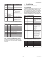
Capabilities
Level
AI
DI
IT
AR
PID
1
1
2
2
1
0
2
1
2
2
1
1
T0402.EPS
4.5 Reading the Parameters
To read AXF parameters, select the AI block of the
AXF from the host screen and read the OUT parameter. The current selected signal is displayed. Check
that MODE_BLOCK of the function block and
resource block is set to AUTO, and change the signal
input and read the parameter again. A new designated
value should be displayed.
4-3
IM 01E20F02-01E
4. GETTING STARTED
4.6 Continuous Record of Values
If the host has a function that continuously records the
indications, use this function to list the indications
(values). Depending on the host being used, it may be
necessary to set the schedule of Publish (the function
that transmits the indication on a periodic basis).
4.7 Generation of Alarm
Generation of an alarm can be attempted from AXF.
Block alarm, Output limit alarm, and Update alarm are
informed to the host. When generating alarm, a Link
Object and a VCR Static Entry need to be set. For
details of Link Object and VCR Static Entry, refer to
section 5.6.1 Link object and section 5.5.1 VCR
Setting.
4-4
IM 01E20F02-01E
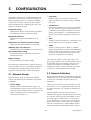
5. CONFIGURATION
5.
CONFIGURATION
This chapter describes how to adapt the function and
performance of the AXF to suit specific applications.
Because multiple devices are connected to Fieldbus, it
is important to carefully consider the device requirements and settings when configuring the system. The
following steps must be taken.
(1)Network design
Determines the devices to be connected to Fieldbus
and checks the capacity of the power supply.
(2)Network definition
Determines the tag and node addresses for all
devices.
(3)Definition of combining function blocks
Determines how function blocks are combined.
(4)Setting tags and addresses
Sets the PD Tag and node addresses for each device.
(5)Communication setting
Sets the link between communication parameters
and function blocks.
(6)Block setting
Sets the parameters for function blocks.
The following section describes in sequence each step
of this procedure. The use of a dedicated configuration
tool significantly simplifies this procedure. Refer to
Appendix 6 when the AXF is used as Link Master.
5.1 Network Design
Select the devices to be connected to the Fieldbus
network. The following are essential for the operation
of Fieldbus.
• Power supply
Fieldbus requires a dedicated power supply. It is
recommended that current capacity be well over the
total value of the maximum current consumed by all
devices (including the host). Conventional DC
current cannot be used as is.
• Terminator
Fieldbus requires two terminators. Refer to the
supplier for details of terminators that are attached
to the host.
• Field devices
Connect the field devices necessary for instrumentation. The AXF has passed the interoperability test
conducted by The Fieldbus Foundation. In order to
properly start Fieldbus, it is recommended that the
devices used satisfy the requirements of the above
test.
• Host
Used for accessing field devices. A minimum of one
device with the bus control function is needed.
• Cable
Used for connecting devices. Refer to “Fieldbus
Technical Information” for details of instrumentation
cabling. Provide a cable sufficiently long to connect
all devices. For field branch cabling, use terminal
boards or a connection box as required.
First, check the capacity of the power supply. The
power supply capacity must be greater than the sum of
the maximum current consumed by all devices to be
connected to Fieldbus. The maximum current consumed for the AXF is 15 mA. The cable used for the
spur must be of the minimum possible length.
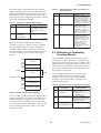
5.2 Network Definition
Before connection of devices with Fieldbus, define the
Fieldbus network. Allocate PD Tag and node addresses
to all devices (excluding such passive devices as
terminators).
The PD Tag is the same as the conventional one used
for the device. Up to 32 alphanumeric characters may
be used for definition. Use a hyphen as a delimiter as
required.
The node address is used to specify devices for
communication purposes. Because this data is too long
for a PD Tag, the host uses the node address in place
of the PD Tag for communication. A range of 20 to
247 (or hexadecimal 14 to F7) can be set. The device
(LM device) with bus control function (Link Master
function) is allocated from a smaller address number
(20) side, and other devices (BASIC device) without
5-1
IM 01E20F02-01E
5. CONFIGURATION
bus control function allocated from a larger address
number (247) side respectively. Place the AXF in the
range of the BASIC device. When the AXF is used as
Link Master, place the AXF in the range of the LM
device. Set the range of addresses to be used to the LM
device. Set the following parameters.
Table 5.2 Operation Parameter Values of the AXF to be
Set to LM Devices
Symbol
V (ST)
Parameters
Slot-Time
Table 5.1 Parameters for Setting Address Range
Symbol
Parameters
Description
V (FUN) First-Unpolled-Node
Indicates the address next
to the address range used
for the host or other LM
device.
V (NUN) Number-ofconsecutiveUnpolled-Node
Unused address range
V (MID) Minimum-Inter-PDUDelay
Not used
0x0F
0x10
Bridge device
LM device
V(FUN)
Unused
V(FUN)V(NUN)
Minimum value of
communication data
intervals. Unit of time is in
octets (256 µs). Set the
maximum specification for
all devices. For AXF, set a
value of 4 or greater.
T0502.EPS
5.3 Definition of Combining
Function Blocks
The input/output parameters for function blocks are
combined. As required, they can be combined with the
input of the control block. The setting is written to the
AXF link object. See “Block setting” in Section 5.6 for
the details. It is also possible to read values from the
host at proper intervals instead of connecting the AXF
block output to other blocks.
0x00
0x13
0x14
Indicates the time
necessary for immediate
reply of the device. Unit of
time is in octets (256 µs).
Set maximum specification
for all devices. For AXF,
set a value of 4 or greater.
V (MRD) Maximum-Reply-Delay The worst case time
elapsed until a reply is
recorded. The unit is Slottime; set the value so that
V (MRD) V (ST) is the
maximum value of the
specification for all
devices. For AXF, the
setting must be a value of
12 or greater.
T0501.EPS
The devices within the address range written as
“Unused” in Figure 5.1 cannot be used on a Fieldbus.
For other address ranges, the range is periodically
checked to identify when a new device is mounted.
Care must be taken to keep the unused device range as
narrow as possible so as to lessen the load on the
Fieldbus.
Description and Settings
V(NUN)
BASIC device
0xF7
0xF8
Default address
0xFB
0xFC
The combined blocks need to be executed synchronously with other blocks on the communications
schedule. In this case, change the AXF schedule
according to the following table. The values in the
table are factory-settings.
Table 5.3 Execution Schedule of the AXF Function Blocks
Portable device address
Index
0xFF
Parameters
F0501.EPS
Figure 5.1 Available Range of Node Addresses
To ensure stable operation of Fieldbus, determine the
operation parameters and set them to the LM devices.
While the parameters in Table 5.2 are to be set, the
worst-case value of all the devices to be connected to
the same Fieldbus must be used. Refer to the specification of each device for details. Table 5.2 lists AXF
specification values.
Setting (Enclosed is
factory-setting)
Cycle (MACROCYCLE)
period of control or
measurement. Unit is 1/32
ms. (16000 = 0.5 s)
269
(SM)
MACROCYCLE_
DURATION
276
(SM)
FB_START_ENTRY.1 AI1 block startup time.
Elapsed time from the start
of MACROCYCLE specified
in 1/32 ms. (0 = 0 s)
277 to FB_START_ENTRY.2 No setting
to
289
(SM) FB_START_ENTRY.14
T0503.EPS
5-2
IM 01E20F02-01E
5. CONFIGURATION
A maximum of 30 ms is taken for execution of AI
block. For scheduling of communications for combination with the next function block, the execution is so
arranged as to start after a lapse of longer than 30 ms.
In no case should function blocks of the AXF be
executed at the same time (execution time is overlapped).
Figure 5.3 shows an example of schedule based on the
loop shown in Figure 5.2.
5.4 Setting of Tags and
Addresses
This section describes the steps in the procedure to set
PD Tags and node addresses in the AXF. There are
three states of Fieldbus devices as shown in Figure 5.4,
and if the state is other than the lowest
SM_OPERATIONAL state, no function block is
executed. AXF must be transferred to this state when
an AXF tag or address is changed.
LIC100
EJX
UNINITIALIZED
(No tag nor address is set)
Tag clear
FIC100
LI100
INITIALIZED
(Only tag is set)
AXF
#1
Address clear
FI100
FC100
Figure 5.2 Example of Loop Connecting Function Block of
the AXF with Other Instruments
IN
LIC100
BKCAL_IN
CAS_IN
BKCAL_OUT
FIC100
FC100
IN
FI100
OUT
F0504.EPS
Figure 5.4 Status Transition by Setting PD Tag and Node
Address
Macrocycle (Control Period)
LI100
OUT
Address setting
SM_OPERATIONAL
(Tag and address are retained, and
the function block can be executed.)
F0502.EPS
Communication
Schedule
Tag setting
BKCAL_IN BKCAL_OUT
Unscheduled
Communication
Scheduled
Communication
F0503.EPS
Figure 5.3 Function Block Schedule and Communication
Schedule
AXF has a PD Tag (FT2001) and node address (244,
or hexadecimal F4) that are set upon shipment from the
factory unless otherwise specified. To change only the
node address, clear the address once and then set a new
node address. To set the PD Tag, first clear the node
address and clear the PD Tag, then set the PD Tag and
node address again.
Devices whose node addresses have been cleared will
have the default address (randomly chosen from a
range of 248 to 251, or from hexadecimal F8 to FB).
At the same time, it is necessary to specify the device
ID in order to correctly specify the device. The device
ID of the AXF is 594543000Bxxxxxxxx. (The
xxxxxxxx at the end of the above device ID is a total
of 8 alphanumeric characters.)
When the control period (macrocycle) is set to more
than 4 seconds, set the following intervals to be more
than 1% of the control period.
- Interval between “end of block execution” and “start
of sending CD from LAS”
- Interval between “end of block execution” and “start
of the next block execution”
5-3
IM 01E20F02-01E
5. CONFIGURATION
5.5 Communication Setting
Table 5.4 VCR Static Entry
Subindex
To set the communication function, it is necessary to
change the database residing in SM-VFD.
Parameter
1
FasArTypeAndRole
Indicates the type and role of
communication (VCR). The
following 4 types are used
for AXF.
0x32: Server (Responds to
requests from host.)
0x44: Source (Transmits
alarm or trend.)
0x66: Publisher (Sends AI
block output to other
blocks.)
0x76: Subscriber (Receives
output of other blocks
by PID block.)
2
FasDllLocalAddr
Sets the local address to
specify VCR in AXF. A range
of 20 to F7 in hexadecimal.
3
FasDllConfigured
RemoteAddr
Sets the node address of the
called party for
communication and the
address (DLSAP or DLCEP)
used to specify VCR in that
address. For DLSAP or
DLCEP, a range of 20 to F7
in hexadecimal is used.
Addresses in Subindex 2
and 3 need to be set to the
same contents of the VCR
as the called party (local and
remote are reversed).
4
FasDllSDAP
Specifies the quality of
communication. Usually, one
of the following types is set.
0x2B: Server
0x01: Source (Alert)
0x03: Source (Trend)
0x91: Publisher/Subscriber
5
FasDllMaxConfirm
DelayOnConnect
To establish connection for
communication, a maximum
wait time for the called
party's response is set in
ms. Typical value is 60
seconds (60000).
6
FasDllMaxConfirm
DelayOnData
For request of data, a
maximum wait time for the
called party's response is
set in ms. Typical value is
60 seconds (60000).
7
FasDllMaxDlsduSize
Specifies maximum DL
Service Data unit Size
(DLSDU). Set 256 for Server
and Trend VCR, and 64 for
other VCRs.
8
FasDllResidual
ActivitySupported
Specifies whether
connection is monitored. Set
TRUE (0xff) for Server. This
parameter is not used for
other communication.
5.5.1 VCR Setting
Set VCR (Virtual Communication Relationship), which
specifies the called party for communication and
resources. AXF has 33 VCRs whose application can be
changed, except for the first VCR, which is used for
management.
AXF has VCRs of four types:
Server(QUB) VCR
A Server responds to requests from a host. This
communication needs data exchange. This type of
communication is called QUB (Queued Usertriggered Bidirectional) VCR.
Source (QUU) VCR
A Source multicasts alarms or trends to other
devices. This type of communication is called QUU
(Queued User-triggered Unidirectional) VCR.
Publisher (BNU) VCR
A Publisher multicasts AI block output to another
function block(s). This type of communication is
called BNU (Buffered Network-triggered Unidirectional) VCR.
Subscriber (BNU) VCR
A Subscriber receives output of another function
block(s) by PID block.
A Server VCR is capable to responding to requests
from a Client (QUB) VCR after the Client successfully
initiates connection to the Server. A Source VCR
transmits data without established connection. A Sink
(QUU) VCR on another device can receive it if the
Sink is configured so. A Publisher VCR transmits data
when LAS requests so. An explicit connection is
established from Subscriber (BNU) VCR(s) so that a
Subscriber knows the format of published data.
Each VCR has the parameters listed in Table 5.4.
Parameters must be changed together for each VCR
because modification of individual parameters may
cause inconsistent operation.
Description
9
FasDllTimelinessClass Not used for AXF.
10
FasDllPublisherTime
WindowSize
Not used for AXF.
11
FasDllPublisher
SynchronizaingDlcep
Not used for AXF.
T0504-1.EPS
5-4
IM 01E20F02-01E
5. CONFIGURATION
Subindex
Parameter
5.6 Block Setting
Description
Set the parameter for function block VFD.
12
FasDllSubsriberTime
WindowSize
13
FasDllSubscriber
Not used for AXF.
SynchronizationDlcep
14
FmsVfdId
Sets VFD for AXF to be
used.
0x1: System/network
management VFD
0x1234: Function block
VFD
15
FmsMaxOutstanding
ServiceCalling
Set 0 to Server. It is not
used for other applications.
16
FmsMaxOutstanding
ServiceCalled
Set 1 to Server. It is not
used for other applications.
17
FmsFeatures
Supported
Indicates the type of
services in the application
layer. In the AXF, it is
automatically set according
to specific applications.
Not used for AXF.
5.6.1 Link Object
A link object combines the data voluntarily sent by the
function block with the VCR. The AXF has 40 link
objects. A single link object specifies one combination.
Each link object has the parameters listed in Table 5.6.
Parameters must be changed together for each VCR
because the modifications made to each parameter may
cause inconsistent operation.
Table 5.6 Link Object Parameters
Subindex
T0504-2.EPS
33 VCRs are factory-set as shown in the table below.
Table 5.5 VCR List
Index
(SM)
VCR
Number
293
1
For system management (Fixed)
294
2
Server (LocalAddr = 0xF3)
295
3
Server (LocalAddr = 0xF4)
296
4
Server (LocalAddr = 0xF7)
297
5
Trend Source (LocalAddr = 0x07,
Remote Address=0x111)
298
6
Publisher for AI (LocalAddr = 0x20)
299
7
Alert Source (LocalAddr = 0x07,
Remote Address=0x110)
300
8
Server (LocalAddr = 0xF9)
301 to 315 9 to 33
Factory Setting
Parameters
Description
1
LocalIndex
Sets the index of function
block parameters to be
combined; set “0” for Trend
and Alert.
2
VcrNumber
Sets the index of VCR to
be combined. If set to “0”,
this link object is not used.
3
RemoteIndex
Not used in AXF. Set to “0”.
4
ServiceOperation
Set one of the following.
Set only one each for link
object for Alert or Trend.
0: Undefined
2: Publisher
3: Subscriber
6: Alert
7: Trend
5
StaleCountLimit
Set the maximum number
of consecutive stale input
values which may be
received before the input
status is set to BAD. To
avoid the unnecessary
mode transition caused
when the data is not
correctly received by
subscriber, set this
parameter to “2” or more.
Not used.
T0505.EPS
5.5.2 Function Block Execution Control
According to the instructions given in Section 5.3, set
the execution cycle of the function blocks and schedule
of execution.
T0506.EPS
Set link objects as shown in Table 5.7.
Table 5.7 Factory-Settings of Link Objects (example)
Index
Link Object #
Factory Settings
30000
1
AI.OUT → VCR#6
30001
2
Trend → VCR#5
30002
3
Alert → VCR#7
30003 to
30039
4 to 40
Not used
T0507.EPS
5-5
IM 01E20F02-01E
5. CONFIGURATION
5.6.2 Trend Object
SMIB
(System
Resource Transducer
Management
block
block
Information
Base)
It is possible to set the parameter so that the function
block automatically transmits Trend. AXF has seven
Trend objects, six of which are used for Trend in
analog mode parameters and one is used for Trend in
discrete mode parameter. A single Trend object
specifies the trend of one parameter.
1
2
3
4
Block Index
Parameter Relative
Index
Sample Type
Sample Interval
Trend
AXF
#1
#1
VCR
#2
#3
#4
#8
#3
#4
#6
#9
#7
#2
#5
DLSAP 0xF8 0xF3 0xF4 0xF7 0xF9 0x20 0x21 0x07
DLCEP
Fieldbus Cable
Description
Host 1
Sets the leading index of
the function block that
takes a trend.
Sets the index of
parameters taking a trend
by a value relative to the
beginning of the function
block. In the AXF AI block,
the following three types of
trends are possible.
7: PV
8: OUT
19: FIELD_VAL
Specifies how trends are
taken. Choose one of the
following 2 types:
1: Sampled upon
execution of a function
block.
2: The average value is
sampled.
5
Last Update
The last sampling time.
List of Status
Status part of a sampled
parameter.
Host 2
Device 1
Device 2
F0505.EPS
Figure 5.5 Example of Default Configuration
5.6.3 View Object
This object forms a group of parameters in a block.
One advantage brought by forming groups of parameters is the reduction of load for data transactions.
View Object has the parameters listed in Table 5.11 to
5.16. Purpose of View Objects is shown in Table 5.10.
Table 5.10 Purpose of Each View Object
Description
Specifies sampling
intervals in units of 1/32
ms. Set the integer
multiple of the function
block execution cycle.
6 to 21
21 to 37 List of Samples
Alert
FBOD
Link
object
Table 5.8 Parameters for Trend Objects
Parameters
DI1 OUT
NMIB
(Network
Management
Information
Base)
Each Trend object has the parameters listed in Table
5.8. The first four parameters are the items to be set.
Before writing to a Trend object, it is necessary to
release the WRITE_LOCK parameter.
Subindex
DI2 OUT
AI OUT
VIEW_1
Set of dynamic parameters required by operator
for plant operation. (PV, OUT, Mode etc.)
VIEW_2
Set of static parameters which need to be
shown to plant operator at once. (Range etc.)
VIEW_3
Set of all the dynamic parameters.
VIEW_4
Set of static parameters for configuration or
maintenance.
T0510.EPS
Data part of a sampled
parameter.
T0508.EPS
Seven trend objects are factory-set as shown Table 5.9.
Table 5.9 Trend Object are Factory-Set
Index
Parameters
32000 to
32007
TREND_FLT.1 to
TREND_FLT.8
No setting
Factory Settings
32008 to
32009
TREND_DIS.1 to
TREND_DIS.2
No setting
T0509.EPS
5-6
IM 01E20F02-01E
5. CONFIGURATION
Table 5.11 View Object for Resource Block
(byte)
Relative
Index
Parameter
(byte)
VIEW VIEW VIEW VIEW
_1
_2
_3
_4
1
ST_REV
2
2
TAG_DESC
3
STRATEGY
2
4
ALERT_KEY
1
5
MODE_BLK
4
6
BLOCK_ERR
7
RS_STATE
8
TEST_RW
2
2
Relative
Index
2
Parameter
VIEW VIEW VIEW VIEW
_1
_2
_3
_4
31
MAX_NOTIFY
4
32
LIM_NOTIFY
1
33
CONFIRM_TIME
4
34
WRITE_LOCK
1
4
35
UPDATE_EVT
2
2
36
BLOCK_ALM
1
1
37
ALARM_SUM
38
ACK_OPTION
2
1
8
8
9
DD_RESOURCE
39
WRITE_PRI
10
MANUFAC_ID
4
40
WRITE_ALM
11
DEV_TYPE
2
41
ITK_VER
12
DEV_REV
1
42
SOFT_REV
13
DD_REV
1
43
SOFT_DESC
14
GRANT_DENY
44
SIM_ENABLE_MSG
15
HARD_TYPES
45
DEVICE_STATUS_1
4
16
RESTART
46
DEVICE_STATUS_2
4
17
FEATURES
47
DEVICE_STATUS_3
4
18
FEATURE_SEL
48
DEVICE_STATUS_4
4
19
CYCLE_TYPE
49
DEVICE_STATUS_5
4
20
CYCLE_SEL
50
DEVICE_STATUS_6
4
21
MIN_CYCLE_T
4
51
DEVICE_STATUS_7
4
22
MEMORY_SIZE
2
52
DEVICE_STATUS_8
4
23
NV_CYCLE_T
53
SOFTDWN_PROTECT
1
24
FREE_SPACE
54
SOFTDWN_FORMAT
1
25
FREE_TIME
55
SOFTDWN_COUNT
26
SHED_RCAS
4
56
SOFTDWN_ACT_AREA
1
27
SHED_ROUT
4
57
SOFTDWN_MOD_REV
16
28
FAULT_STATE
58
SOFTDWN_ERROR
2
29
SET_FSAFE
30
CLR_FSAFE
2
2
2
2
1
2
4
4
4
1
4
1
Totals
2
22
30
73
35
T0511-2.EPS
T0511-1.EPS
5-7
IM 01E20F02-01E
5. CONFIGURATION
Table 5.12 View Object for Transducer Block
(byte)
Relative
Index
Parameter Mnemonic
1
2
3
4
5
6
7
8
9
10
11
12
13
14
15
16
17
18
19
20
21
22
23
24
25
26
27
28
29
30
31
32
33
34
35
36
37
38
39
40
41
42
43
44
45
46
47
ST_REV
TAG_DESC
STRATEGY
ALERT_KEY
MODE_BLK
BLOCK_ERR
UPDATE_EVT
BLOCK_ALM
TRANSDUCER_DIRECTORY
TRANSDUCER_TYPE
XD_ERROR
COLLECTION_DIRECTORY
PRIMARY_VALUE_TYPE
PRIMARY_VALUE
PRIMARY_VALUE_RANGE
CAL_POINT_HI
CAL_POINT_LO
CAL_MIN_SPAN
CAL_UNIT
SENSOR_TYPE
SENSOR_RANGE
SENSOR_SN
SENSOR_CAL_METHOD
SENSOR_CAL_LOC
SENSOR_CAL_DATE
SENSOR_CAL_WHO
LIN_TYPE
SECONDARY_VALUE
SECONDARY_VALUE_UNIT
LANGUAGE
DISPLAY_SELECT1
DISPLAY_SELECT2
DISPLAY_SELECT3
NOMINAL_SIZE_UNIT
NOMINAL_SIZE
PRIMARY_VALUE_FTIME
AUTO_ZERO_EXE
MAGFLOW_ZERO
LOW_MF
HIGH_MF
LOW_MF (EDF)
HIGH_MF (EDF)
SELECT_FLOW_TUBU
MEASURE_MODE
PRIMARY_VALUE_LOWCUT
BI_DIRECTION
FLOW_DIRECTION
VIEW VIEW VIEW VIEW VIEW VIEW VIEW VIEW VIEW VIEW VIEW
_1 _2 _3 _3 _4 _4 _4 _4 _4 _4 _4
4
5
6
7
1st 2nd 1st 2nd 3
2
2
2
2
2
2
2
2
2
2
(byte)
Relative
Index
48
49
50
51
52
53
54
55
56
57
58
59
60
61
62
63
64
65
66
67
68
69
70
71
72
73
74
75
76
77
78
79
80
81
82
83
84
85
86
87
88
89
90
91
2
2
1
4
2
4
2
2
1
2
2
1
2
2
5
5
11
4
4
4
2
2
11
32
1
32
7
32
1
5
2
1
1
1
1
2
4
4
1
4
4
4
4
4
1
1
4
1
1
Parameter Mnemonic
VELOCITY_CHECK
DENSITY_UNIT
MASS_FLOW_DENSITY
LIMSW_1_VALUE_D
LIMSW_1_TARGET
LIMSW_1_SETPOINT
LIMSW_1_ACT_DIRECTION
LIMSW_1_HYSTERESIS
LIMSW_1_UNIT
LIMSW_2_VALUE_D
LIMSW_2_TARGET
LIMSW_2_SETPOINT
LIMSW_2_ACT_DIRECTION
LIMSW_2_HYSTERESIS
LIMSW_2_UNIT
SWITCH_1_VALUE_D
SWITCH_1_TARGET
SWITCH_2_VALUE_D
SWITCH_2_TARGET
SIGNAL_LOCK
DISPLAY_CYCLE
RATE_LIMIT
DEAD_TIME
PULSING_FLOW
POWER_SYNCH
POWER_FREQUENCY
SOFTWARE_REV_NO
ALARM_PERFORM
OPERATION_TIME
ALM_RECORD1
ALM_RECORD_TIME1
ALM_RECORD2
ALM_RECORD_TIME2
ALM_RECORD3
ALM_RECORD_TIME3
ALM_RECORD4
ALM_RECORD_TIME4
ALARM_SUM
ADHESION_CHECK
ADHESION_LEVEL1
ADHESION_LEVEL2
ADHESION_LEVEL3
ADHESION_LEVEL4
ADH_MEASURE_VALUE
Total
VIEW VIEW VIEW VIEW VIEW VIEW VIEW VIEW VIEW VIEW VIEW
_1 _2 _3 _3 _4 _4 _4 _4 _4 _4 _4
1st 2nd 1st 2nd 3
4
5
6
7
4
1
4
2
1
4
1
4
1
2
1
4
1
4
1
2
1
2
1
1
1
4
4
1
1
4
8
4
16
1
16
1
16
1
16
1
16
8
1
4
4
4
4
4
16 66 41 86 72 74 71 2
2
2
2
T0512.EPS
5-8
IM 01E20F02-01E
5. CONFIGURATION
Table 5.13 View Object for AI Function Block
Table 5.14 View Object for DI (DI1, DI2) Function Block
(byte)
Relative
Index
Parameter
(byte)
VIEW VIEW VIEW VIEW
_3
_1
_2
_4
1
ST_REV
2
2
2
TAG_DESC
3
STRATEGY
4
ALERT_KEY
5
MODE_BLK
4
6
BLOCK_ERR
7
PV
8
OUT
9
SIMULATE
10
XD_SCALE
11
12
13
IO_OPTS
14
STATUS_OPTS
15
16
17
18
19
FIELD_VAL
20
UPDATE_EVT
21
BLOCK_ALM
22
ALARM_SUM
23
ACK_OPTION
2
24
ALARM_HYS
4
25
HI_HI_PRI
1
26
HI_HI_LIM
4
27
HI_PRI
1
28
HI_LIM
4
29
LO_PRI
1
30
LO_LIM
4
31
LO_LO_PRI
1
32
LO_LO_LIM
4
33
HI_HI_ALM
34
HI_ALM
35
LO_ALM
36
LO_LO_ALM
2
Relative
Index
2
Parameter
1
ST_REV
2
TAG_DESC
2
3
STRATEGY
1
VIEW VIEW VIEW VIEW
_3
_1
_2
_4
2
2
2
2
2
1
4
ALERT_KEY
4
5
MODE_BLK
4
4
2
2
6
BLOCK_ERR
2
2
5
5
7
PV_D
2
2
5
5
8
OUT_D
2
2
9
SIMULATE_D
11
10
XD_STATE
2
OUT_SCALE
11
11
OUT_STATE
2
GRANT_DENY
2
12
GRANT_DENY
2
2
13
IO_OPTS
2
2
14
STATUS_OPTS
2
CHANNEL
2
15
CHANNEL
2
L_TYPE
1
16
PV_FTIME
4
LOW_CUT
4
17
FIELD_VAL_D
PV_FTIME
4
18
UPDATE_EVT
19
BLOCK_ALM
20
ALARM_SUM
21
ACK_OPTION
2
22
DISC_PRI
1
23
DISC_LIM
1
24
DISC_ALM
Total
5
5
8
8
31
26
31
Total
2
2
8
8
22
8
22
19
T0514.EPS
46
T0513.EPS
5-9
IM 01E20F02-01E
5. CONFIGURATION
Table 5.15 View Object for (IT1, IT2) Function Block
Table 5.16 View Object for AR Function Block
(byte)
Relative
Index
Parameter
1
ST_REV
2
TAG_DESC
3
STRATEGY
4
ALERT_KEY
5
MODE_BLK
6
7
(byte)
VIEW VIEW VIEW VIEW
_3
_1
_2
_4
2
2
2
Relative
Index
2
Parameter
1
ST_REV
2
TAG_DESC
2
3
STRATEGY
1
VIEW VIEW VIEW VIEW
_3
_1
_2
_4
2
2
2
2
2
1
4
ALERT_KEY
4
4
5
MODE_BLK
BLOCK_ERR
2
2
6
TOTAL_SP
4
4
7
8
OUT
5
5
8
9
OUT_RANGE
11
9
10
GRANT_DENY
2
10
PV_SCALE
11
11
STATUS_OPTS
11
OUT_RANGE
11
12
IN_1
5
5
12
GRANT_DENY
2
13
IN_2
5
5
13
INPUT_OPTS
14
OUT_TRIP
2
2
14
IN
5
15
OUT_PTRIP
2
2
15
IN_LO
5
16
TIME_UNIT1
1
16
IN_1
5
17
TIME_UNIT2
1
17
IN_2
5
18
UNIT_CONV
4
18
IN_3
5
19
PULSE_VAL1
4
19
RANGE_HI
4
20
PULSE_VAL2
4
20
RANGE_LO
4
21
REV_FLOW1
2
2
21
BIAS_IN_1
4
22
REV_FLOW2
2
2
22
GAIN_IN_1
4
23
RESET_IN
2
2
23
BIAS_IN_2
4
24
STOTAL
4
24
GAIN_IN_2
4
25
RTOTAL
4
25
BIAS_IN_3
4
26
SRTOTAL
4
26
GAIN_IN_3
4
27
SSP
4
27
COMP_HI_LIM
4
28
INTEG_TYPE
1
28
COMP_LO_LIM
4
29
INTEG_OPTS
2
29
ARITH_TYPE
1
30
CLOCK_PER
4
30
BAL_TIME
4
31
PRE_TRIP
4
31
BIAS
4
32
N_RESET
4
4
32
GAIN
4
33
PCT_INCL
4
4
33
OUT_HI_LIM
4
34
GOOD_LIM
4
34
OUT_LO_LIM
4
35
UNCERT_LIM
4
35
UPDATE_EVT
36
OP_CMD_INT
36
BLOCK_ALM
37
OUTAGE_LIM
38
RESET_CONFIRM
39
UPDATE_EVT
40
BLOCK_ALM
41
ACCUM_TOTAL
Total
2
4
1
1
4
BLOCK_ERR
2
2
PV
5
5
OUT
5
5
PRE_OUT
5
Total
4
2
4
5
2
23
26
48
68
T0517.EPS
2
4
52
17
64
42
T0516.EPS
5-10
IM 01E20F02-01E
5. CONFIGURATION
Table 5.17 Indexes of View for Each Block
VIEW_1 VIEW_2 VIEW_3 VIEW_4
Resourse Block
40100
40101
40102
40103
Transducer Block
40200
AI Function Block
40400
40201
40202
40203
40401
40402
40403
DI1 Function Block
DI2 Function Block
40600
40601
40602
40603
40610
40611
40612
40613
PID Function Block
40800
40801
40802
40803
IT1 Function Block
41600
41601
41602
41603
IT2 Function Block
41610
41611
41612
41613
AR Function Block
41750
41751
41752
41753
T0515.EPS
5.6.4 Function Block Parameters
Function block parameters can be read from the host or
can be set. For a list of the parameters of Resource
block, Transducer block, AI block and DI block, refer
to “9. PARAMETER LISTS”. For other function
blocks, refer to Appendix.
5-11
IM 01E20F02-01E
6. EXPLANATION OF BASIC ITEMS
6.
EXPLANATION OF BASIC ITEMS
6.1 Outline
This chapter describes basic TR (Transducer block),
AI, and DI function block parameter setting, displays
of the integral indicator. Refer to Appendixes other
function blocks and LM function.
6.2 Setting and Changing Parameters for the Whole Process
IMPORTANT
This chapter contains information on how to adapt the
function and performance of the ADMAG AXF to suit
specific applications. Because two or more devices are
connected to FOUNDATION Fieldbus, settings including
the requirements of all devices need to be determined.
Practically, the following steps must be taken.
The following section describes each step of the
procedure in the order given. Using a dedicated
configuration tool allows the procedure to be significantly simplified. This section describes the procedure
which has relatively simple functions.
Do not turn off the power immediately after
setting. When the parameters are saved to the
EEPROM, the redundant processing is executed
for an improvement of reliability. If the power is
turned off within 60 seconds after setting is
made, the modified parameters are not saved
and the setting may return to the original values.
Block mode
Many parameters require a change of the block mode
of the function block to O/S (Out of Service) when
their data is changed. To change the block mode of the
function block, its MODE_BLK needs to be changed.
The MODE_BLK is comprised of four sub-parameters
below.
(1) Target (Target mode):
Sets the operating condition of the block.
(2) Actual (Actual mode):
Indicates the current operating condition.
(3) Permit (Permitted mode):
Indicates the operating condition that the block
is allowed to take.
(4) Normal (Normal mode):
Indicates the operating condition that the block
will usually take.
6-1
IM 01E20F02-01E
6. EXPLANATION OF BASIC ITEMS
6.3 Transducer Block Parameters
The transducer block sets functions specific to the flow
rate measurement of the ADMAG AXF. Figure6.3.1
presents the diagram of the Transducer block.
Flow rate
operation
Dual freq.
operation
Rate limit
damping
Lowcut
Limit check
SENSOR
PRIMARY_VALUE
(Channel1)
LIMSW_1_VALUE_D
(Channel2)
LIMSW_2_VALUE_D
(Channel3)
Adhesion check
Historical
records
Equipment
information
SWITCH_1_VALUE_D
(Channel4)
SWITCH_2_VALUE_D
(Channel5)
F0601.eps
Figure 6.3.1
Diagram of the Transducer Block
For a list of the parameters of each block of the
ADMAG AXF, refer to "List of parameters for each
block of the ADMAG AXF" in Chapter 9. The
following is a list of important parameters.
NOMINAL_SIZE:
Sets the size of the flowtube.
NOMINAL_SIZE_UNIT:
Sets the unit of the flowtube size.
LOW_MF:
Sets the meter factor of low frequency side for standard dual frequency excitation.
HIGH_MF:
Sets the meter factor of high frequency side for
standard dual frequency excitation.
PRIMARY_VALUE_RANGE:
Shows the range of PRIMARY_VALUE. The engineering units must match the units selected in the
parameter XD_SCALE of the AI Block that reads the
channel with this value.
PRIMARY_VALUE_FTIME:
Sets the time constant of damping to the flow rate
calculation.
PRIMARY_VALUE_LOWCUT:
Sets low cut range for output. Setting range is 0 to
10% of PRIMARY_VALUE_RANGE. EU_100.
"0%" is factory set.
Normally low cut be set by this parameter, not by
LOW_CUT of AI function block.
LOW_MF(EDF):
Sets the meter factor of low frequency side for enhanced dual frequency excitation.
HIGH_MF(EDF):
Sets the meter factor of high frequency side under
enhanced dual frequency excitation.
6-2
IM 01E20F02-01E
6. EXPLANATION OF BASIC ITEMS
DISPLAY_SELECT1, 2, 3:
Table 6.3.1 DISPLAY SELECT
DISPLAY_SELEC T 1
The display content for the display
unit's first line.
DISPL AY_SELE CT 2
DISPL AY_SELE CT 3
The display content for the display unit's
second line.
The display content for the display
unit's third line.
1:Off
1:Flow Rate(%)
1:Off
2:Flow Rate
2:Flow Rate(%)
2:Flow Rate(%)
3:Integrator1 Out
3:Flow Rate
3:Flow Rate
4:Integrator2 Out
4:Flow Rate(Bar)
4:Flow Rate(Bar)
5:Arithmetic Out
5:Integrator1 Out
5:Integrator1 Out
The factory default setting is 2.
6:Integrator2 Out
6:Integrator2 Out
7:Arithmetic Out
7:Arithmetic Out
8:PD Tag
8:PD Tag
9:Adhesion Check
9:Adhesion Check
10:Communication
10:Communication
The factory default setting is 1.
The factory default setting is 1.
T0601.eps
DISPLAY_CYCLE:
Sets the cycle of LCD display. The factory default
setting of the display cycle is 2: 400ms. The valid
range can be selected from below;
1: 200ms
2: 400ms
3: 1s
4: 2s
5: 4s
6: 8s
If the low temperature environment makes it difficult
to view the display, it is recommended that you set a
longer display cycle.
PRIMARY_VALUE_TYPE:
Indicates the measuring value type used in
PRIMARY_VALUE. Valid range are as follows;
100: mass flow
101: volumetric flow
102: average mass flow
103: average volumetric flow
65535: other
Factory default is 101: volumetric flow.
6-3
IM 01E20F02-01E
6. EXPLANATION OF BASIC ITEMS
6.4 AI Function Block Parameters
AI Function block parameters can be read or set from
the host. Figure6.4.1 presents the diagram of AI
Function block.
Alarms
HI,HI_HI
LO,LO_LO
IO_OPTS.Low cutoff
SIMULATE.Enable
LOW_CUT
=1 (Enable)
FIELD_VAL.Value
Simulate
SIMULATE.Transducer
Value
L_TYPE
PV.Value
Disable
Enable
Ind.Sqr Root
Scaling
XD_SCALE
✓/100
/100
AUTO
Scaling
OUT_SCALE
Filter
PV_FTIME
OUT
Indirect
Simulate
SIMULATE.Simulate
Value
Direct
MODE_BLK.Actual
F0602.eps
Figure 6.4.1 Diagram of AI Functional Block
For a list of the parameters of blocks held by the
ADMAG AXF, refer to "List of parameters for each
block of the ADMAG AXF" in Chapter 9. The
following is a list of important parameters with a guide
how to set them.
TAG_DESC, MODE_BLK:
Indicates the three types of function block modes;
Out_Of_Service, Manual, and Auto. TAG_DESC
indicates what mode of operation is desired for AI
Function block. In Out_Of_Service (O/S) mode, the AI
block does not operate. The Manual mode does not
allow values to be updated. The Auto mode causes the
measured value to be updated. Under normal circumstances, set the Auto mode to take effect. For
MODE_BLK the Auto mode is the factory default.
CHANNEL:
This is the parameter of the transducer block to be
input to the AI block. AI block is assigned flow rate.
6-4
IM 01E20F02-01E
6. EXPLANATION OF BASIC ITEMS
OUT:
This parameter contains the current measurement value
from Transducer Block or configuration adjusted
engineering unit and the belonging state in AUTO
MODE. OUT contains the value and status set by an
operator in MAN MODE.
Quality
Sub-status
Limit
Non-specific
Alarm
Normal
Active Block Alarm
Block Alarm is Active
0:Not Limited
Active Advisory Alarm
Advisory Alarm is Active
1:Low Limited
Good(NC)
Active Critical Alarm
Critical Alarm is Active
2:High Limited
Unack. Block Alarm
Uncertain
3:Constant
Block Alarm is Unacknowledged
Unack. Advisory Alarm
Advisory Alarm is Active
Unack. Critical Alarm
Critical Alarm is Active
Engineering Unit Range
Violation
Out of sensor operating range
-Out of range of min. span and max. span
FB board EEPROM failure
No-specific
--
TB is O/S
BLOCK_ERR is O/S etc.
Bad
0:Not Limited
EEPROM failure
1:Low Limited
Internal communication error
Device Failure
2:High Limited
Sensor Failure
CPU board failure
3:Constant
Out of Service
--
RS, AI are O/S
T0602.eps
XD_SCALE:
Scale of input from the transducer block. The maximum flow rate range on an order sheet is set. "0" (0%),
"10.000"(100%), and "m/s" for the unit are factory-set
unless specified in the order. Changing the unit (can be
set only in flow rate) also causes the unit within the
transducer block to be automatically changed.(The unit
is automatically changed according to the unit selected
in AI. Units which can be set by XD_SCALE are
shown in Table 6.4.1.
6-5
IM 01E20F02-01E
6. EXPLANATION OF BASIC ITEMS
Table 6.4.1 Unit Codes
Time unit
Volume/
Mass unit
t/d (1329)
kg/d(1325)
g/d (1321)
ft3/d (1359)
Mgal (US)/d (1366)
kgal (US)/d (1462)
gal(US)
gal (US)/d (1365)
mgal (US)/d (1461)
kbbl (US Oil)/d (1493)
bbl(US Oil) bbl (US Oil)/d (1374)
mbbl (US Oil)/d (1492)
bbl (US Oil)/d (1491)
kbbl (US Beer)/d (65525)
bbl(US Beer) bbl (US Beer)/d (65529)
mbbl (US Beer)/d (65533)
h
Ml/h (65521)
kL/h (1519)
L/h (1353)
m3/ h (1349)
cm3/h (1513)
t/h (1328)
kg/h (1324)
g/h (1320)
CFH (1358)
Mgal (US)/h (1459)
kgal (US)/h (1458)
gal (US)/h (1364)
mgal (US)/h (1457)
kbbl (US Oil)/h (1489)
bbl (US Oil)/h (1373)
mbbl (US Oil)/h (1488)
bbl (US Oil)/h (1487)
kbbl (US Beer)/h (65524)
bbl (US Beer)/h (65528)
mbbl (US Beer)/h (65532)
min
Ml/min (65520)
kL/min (1518)
L/min (1352)
m3/min (1348)
cm3/min (1512)
t/min (1327)
kg/min (1323)
g/min (1319)
CFM (1357)
Mgal (US)/min (1455)
kgal (US)/min (1454)
GPM (1363)
mgal (US)/min (1453)
kbbl (US Oil)/min (1485)
bbl (US Oil)/min (1372)
mbbl (US Oil)/min (1484)
bbl (US Oil)/min (1483)
bbl (US Beer)/min (65527)
mbbl (US Beer)/min (65531)
bbl (US Beer)/min (65535)
m3/s (1347)
cm3/s (1511)
m/s (1061)
t/s (1326)
kg/s (1322)
g/s (1318)
CFS (1356)
Mgal (US)/s (1451)
kgal (US)/s (1450)
gal (US)/s (1362)
mgal (US)/s (1449)
kbbl (US Oil)/s (1481)
bbl (US Oil)/s (1371)
mbbl (US Oil)/s (1480)
bbl (US Oil)/s (1479)
bbl (US Beer)/s (65526)
mbbl (US Beer)/s(65530)
bbl (US Beer)/s
lb
ft
lb (US)/h (1332)
-
lb (US)/min (1331)
-
lb (US)/s (1330)
ft/s (1067)
L
m3
cm3
m
t
kg
g
CF
d
Ml/d (1355)
kL/d (1520)
L/d (1354)
m3/d (1350)
cm3/d (1514)
lb (US)/d (1333)
-
s
kL/s (65522)
L/s (1351)
T0603.eps
OUT_SCALE:
Set the range of output (from 0% to 100%). In the case
of AXF, OUT_SCALE is always the same setting as
XD_SCALE.
L_TYPE:
L_TYPE is always selected as "Direct".
(Note) "Indirect" also can be set.
PV_FTIME:
Sets the time constant of the damping function within
AI block (primary delay) in seconds.
For normal magmeter’s damping setting, set by
PRIMARY_VALUE_FTIME of transducer block
instead of setting AI function block’s PV_FTIME.
6-6
IM 01E20F02-01E
6. EXPLANATION OF BASIC ITEMS
6.5 DI Function Block Parameters
DI Function block parameters can be read or set from
the host. Figure6.5.1 presents the diagram of DI
Function block.
PV_D
CHANNEL
Simulate
Optional
Filter
SIMULATE_D
Invert
PV_FTIME
Output
OUT_D
FIELD_VAL_D
Alarms
DISC
MODE
F0603.eps
Figure 6.5.1
Diagram of DI Function Block
ADMAG AXF contains two DI function blocks, which
individually transfer the "Flow switch" and "Adhesion
Alarm/warning" generated by the transducer block. For
a list of the parameters of blocks held by the ADMAG
AXF, refer to "List of parameters for each block of the
ADMAG AXF" in Chapter 9. The following is a list of
important parameters with a guide to how to set them.
Each DI block is assigned to either "Flow switch" or
"Adhesion Alarm/warning".
MODE_BLK:
Indicates the three types of function block modes;
Out_Of_Service, Manual, and Auto. MODE_BLK
indicates what mode of operation is desired for DI
Function block. In Out_Of_Service mode, the DI block
does not operate. The Manual mode does not allow
values to be updated. The Auto mode permits the
measured value to be updated. Under normal circumstances, set the Auto mode to take effect. The Auto
mode is the factory default.
DISC_PRI
Deternines the priority level of the discrete alarm on
the block's output (OUT_D). The alarm will be
transmitted upon occurrence only when the DISC_PRI
is set at 3 or higher. This parameter is set to 1 before
the AXF is shipped from the factory.
CHANNEL:
This is the parameter to specify the value of the
transducer block to be input to the DI block.
Value
Content
2
LIMSW_1
3
LIMSW_2
4
SWITCH_1
5
SWITCH_2
PV_FTIME
Stipulates the delay time (in seconds) of changing the
output value after a change of the value inside the DI
block.
Table 6.5.1 Alarm Priority
Value
0
1
3 to 7
8 to 15
Description
Alert is not notified. Alarm parameters are not updated.
Alert is not notified.
Advisory alarms.
Critical alarms.
T0605.eps
DISC_LIM
Setpoint of the discrete alarm; when the value of
OUT_D agrees with the value set in DISC_LIM, the
discrete alarm is generated.
T0604.eps
6-7
IM 01E20F02-01E
6. EXPLANATION OF BASIC ITEMS
6.6 Integral LCD Indicator
Flow Rate
Flow rate is displayed together with the units set in
XD_SCALE, the maximum number of figures is six.
Employing 32*132 full dot matrix backlit LCD,
various display can be obtained.
FR
6.6.1 Flow Data Display
By the transducer block parameters setting in
DISPLAY_SELECT1, 2, 3 as described in 6.3, up to
three lines display can be made among the following
data.
-Flow Rate(%)
-Flow Rate
-Flow Rate(Bar)
-Integrator1 Out
-Integrator2 Out
-Arithmetic Out
-PD Tag
-Adhesion Check
-Communication
The number of the data can be configured by setting
DISPLAY_SELECT1, 2, 3 as follows;
Display Select1
Display Select2
Display Select3
1 line display
Off
-
2 line display
Other than "Off"
Off
3 line display
Other than "Off"
Other than "Off"
- 123 . 456
k g a l / m i n
F0606.eps
In the case of L_TYPE is "Direct " decimal point
location of the data becomes as follows.
Example
0
0
123
1
1
123.4
2
2
123.45
3
3
123.456
Other
Auto
Refer to below
T0607.eps
XD_SCALE.EU_0,EU_100
set value
Desimal Point Example
Location
0
-33333
XD_SCALE value -10000
-10000 < XD_SCALE value -1000
1
-4444.1
-1000 < XD_SCALE value -100
2
-555.12
T0606.eps
: Flow Rate, Flow Rate(%)
I T 1 : Integrator1 Out
I T 2 : Integrator2 Out
AR
Desimal
Point
Location
When XD_SCALE.Units_Index is set as Other decimal
point location of the data becomes as follows.
The data titles are displayed together with the flow
data and units.
FR
XD_SCALE.Units_Index
: Arithmetic Out
T A G : PD Tag
-100 < XD_SCALE value -10
-10 < XD_SCALE value < 10
3
3
10 XD_SCALE value < 100
100 XD_SCALE value < 1000
1000 XD_SCALE value < 10000
3
2
1
-66.123
-7.123
0.123
66.123
555.12
4444.1
10000 XD_SCALE value
0
33333
T0608.eps
A D H : Adhesion Check
*XD_SCALEvalue : Max (|XD_SCALE.EU0|, |XD_SCALE.EU100|)
C O M : Communication
F0604.eps
When the flow data exceeds the maximum number of
figures six, then "84:Disp Over Wng" message is
displayed.
Flow Rate (%)
100 . 0
FR
999.999
%
FR
l / h
1 2 3 4 5 6
M l
8 4 : D i s p
O v e r
W n g
F0605.eps
Decimal point is always to the first place.
I T 1
F0607.eps
6-8
IM 01E20F02-01E
6. EXPLANATION OF BASIC ITEMS
Flow Rate Unit Display on LCD
Flow Rate Unit Display is shown by the following
table corresponding to the XD_SCALE Units Codes.
Table 6.6.1 Display Unit Codes
Units Codes
LCD Display
Unit [/d]
Units Codes
LCD Display
Unit [/h]
LCD Display
Unit [/min]
Units Codes
LCD Display
Unit [/s]
Units Codes
1355:Ml /d
M l /d
65521:M l /h
M l/h
65520:Ml /mi n
M l /min
1350:m3/d
m 3/d
1349:m3/h
m 3/h
1348:m3/mi n
m 3/mi n
1347:m3/s
m 3/s
1520:k L /d
kl /d
1519:k L /h
kl /h
1518:k L /mi n
k l /mi n
65522:k L /s
kl /s
1354:L/d
l /d
1353:L/h
l /h
1352:L/m i n
l /mi n
1351:L/s
l /s
1514:cm3/d
cm 3/d
1513:cm3/h
cm 3/h
1512:cm3/mi n
cm 3/mi n
1511:cm3/s
cm 3/s
1061:m/s
m/s
1329:t/ d
t /d
1328:t/h
t /h
1327:t /mi n
t /mi n
1326:t/s
t /s
1325:kg/d
kg/d
1324:k g/h
kg/h
1323:kg/mi n
k g/mi n
1322:k g/s
kg/s
1321:g/d
g/d
1320:g/h
g/h
1319:g/mi n
g/mi n
1318:g/s
g/s
1359:ft3 /d
cf/d
1358:CFH
cf/h
1357:CFM
cf/mi n
1356:CFS
cf/s
1366:Mgal (US)/d
M gal /d
1459:M gal (U S)/h
Mgal /h
1455:Mgal (US)/mi n
Mgal /mi n
1451:Mgal (US)/s
M gal/s
1462:kgal(US)/d
k gal/d
1458:kgal (US)/h
k gal /h
1454:kgal(US)/mi n
kgal/mi n
1450:kgal (US)/s
k gal /s
1365:gal(US)/d
gal /d
1364:gal(US)/h
gal /h
1363:GPM
gal /mi n
1362:gal(US)/s
gal /s
1461:mgal (US)/d
mgal /d
1457:mgal (US)/h
mgal/h
1453:mgal (US)/mi n
mgal /mi n
1449:mgal (US)/s
mgal /s
1493:k bbl (U S Oi l )/d
kbbl /d
1489:kbbl (US Oi l )/h
kbbl /h
1485:k bbl (US Oi l )/mi n
k bbl /mi n
1481:kbbl (US Oi l )/s
kbbl /s
1374:bbl (US Oi l )/d
bbl /d
1373:bbl (US Oi l )/h
bbl /h
1372:bbl (US Oil )/mi n
bbl /mi n
1371:bbl (US Oi l )/s
bbl /s
1492:mbbl (US Oi l )/d
mbbl /d
1488:mbbl (US Oi l )/h
mbbl /h
1484:mbbl(US Oil)/min
mbbl /mi n
1480:mbbl (US Oil )/s
mbbl /s
1491:ubbl (US Oi l )/d
bbl/d
1487:ubbl (US Oi l )/h
bbl/h
1483:ubbl(US Oil)/min
bbl/min
1479:ubbl (US Oi l )/s
bbl/s
65525:kbbl (US Beer)/d
kbbl /d
65524:kbbl(US Beer)/h
kbbl/h
65529:bbl (US Beer )/d
65533:mbbl(US Beer)/d
1333:l b(US)/d
bbl /d
65528:bbl(US Beer)/h
bbl /h
mbbl /d
65532:mbbl(US Beer)/h
mbbl /h
l b/d
1332:l b(US)/h
l b/h
65527:bbl(US Beer)/min
65531:mbbl(US Beer)/min
bbl /mi n
65526:bbl(US Beer)/s
bbl /s
mbbl /min
65530:mbbl(US Beer)/s
mbbl /s
65535:ubbl(US Beer)/min
bbl/min
65534:ubbl(US Beer)/s
bbl/s
1331:l b(US)/mi n
l b/mi n
1330:l b(U S)/s
l b/s
1067:ft/s
ft/s
T0609.eps
Flow Rate (Bar)
Bi Direction is set "Unidirectional"
12345678
The decimal point location of the data becomes as
follows depending on the setting of IT block
OUT_RANGE. Decimal_Point
AR
IT1 or IT2:OUT_RANGE.Decimal_Point
M l
0
0
1
2
3
4
5
6
7
Other
100
F0608.eps
Bi Direction is set "Bidirectional"
12345678
AR
M l
-100
100
F0609.eps
Integrator1 Out, Integrator2 Out
The maximum number of figures is eight in addition to
sign (!) for Integrator Out display.
87654321
12345
8
Desimal Point
Location
0
1
2
3
4
5
6
7
0
Example
12345678
1234567.8
123456.78
12345.678
1234.5678
123.45678
12.345678
1.2345678
12345678
T0610.eps
Integrator Out Unit Display
Only when the following units are set in IT1 or IT2
:OUT_RANGE.Units_Index the unit is displayed on
LCD, otherwise eight charactor space is displayed.
Table 6.6.2 Integrator Unit Display
Units Codes
65523:Ml
1034:m 3
1035:dm 3
1517:kL
1041:hL
1038:L
1040:mL
1036:cm 3
1092:t
I T 1
M l
I T 2
M l
F0610.eps
LCD Display
Unit
Ml
m3
dm 3
kl
hl
l
ml
cm 3
t
Units Codes
LCD Display Unit
1091:Mg
1088:kg
1089:g
1090:mg
1043:CF
1048:gallon
1051:bbl
1094:lb
1588:no units
Mg
kg
g
mg
cf
gal
bbl
lb
space
T0611.eps
6-9
IM 01E20F02-01E
6. EXPLANATION OF BASIC ITEMS
Arithmetic Out
The display is given in the same manner as Integrator
Out, decimal point is set by
"AR:OUT_RANGE.Decimal_Point".
FR
123.456
l / h
L e v e l : 2
A D H
F0615.eps
AR:OUT_RANGE.Decimal_Point
AR
:OUT_RANGE.Decimal_Point
0
1
2
3
4
5
6
7
Other
Desimal Point
Location
0
1
2
3
4
5
6
7
0
Example
12345678
1234567.8
123456.78
12345.678
1234.5678
123.45678
12.345678
1.2345678
12345678
Level1 : Adhesion Level2 " Adh Measure Value >
Adhesion Level1
FR
123.456
l / h
L e v e l : 1
T0650.eps
PD Tag
The third line shows the example of PD Tag display.
Maximum number of figures is 16, on LCD the head
16 charactors out of 32 charactors of management PD
Tag can be displayed.
123. 456
A D H
F0616.eps
Level0 : Adhesion Level1 " Adh Measure Value
FR
123.456
l / h
L e v e l : 0
FR
A D H
F0617.eps
l / h
M l
9 8 7 6 5 4
A X F - P l a c e 1
I T 1
T A G
F0611.eps
Communication
The third line shows the example of Communication
display.
Adhesion Check
When Adhesion Check display is selected result is
displayed as below showing the level number.
9 8 7 6 5 4
F o u n d a t i o n
FR
l / h
M l
I T 2
F i e l d b u s C O M
FR
123.456
l / h
L e v e l : 2
123.456
F0618.eps
A D H
6.6.2 Display Modes
F0612.eps
ADMAG AXF has following display modes.
Adhesion Check Level Judge
Level4 : Adh Measure Value > Adhesion Level4
123.456
l / h
L e v e l : 4
- Normal Display
- Alarm Display
- Warning Display
- Autozero Display
FR
A D H
F0613.eps
Display Renewal Time
Display renewal time for each display modes depends
on Display Cycle setting;
Level3 : Adhesion Level4 " Adh Measure Value >
Adhesion Level3
123.456
l / h
L e v e l : 3
Display Cycle set Time
2s,1s,400ms,200ms
4s
2s
4s
Normal Display
4s
4s
Alarm Display
4s
4s
Warning Display
30s
Autozero Display
Display Mode
FR
8s
8s
8s
8s
T0612.eps
A D H
F0614.eps
Level2 : Adhesion Level3 " Adh Measure Value >
Adhesion Level2
Normal Display
In this display mode various flow data from one to
three lines are displayed as described in 6.5.1.
6-10
IM 01E20F02-01E
6. EXPLANATION OF BASIC ITEMS
Alarm Display
100.123
1 2 3 4 5 6
F o u n d a t i o n
FR
l / h
I T 2
M l
F i e l d b u s C O M
Alarm generated
P r
3
F i
f l
o
1
l
u
c e s s
A l a r m
: E mp t y
P i p e
l
f l o w
t u b e
i d
100.123
1 2 3 4 5 6
F o u n d a t i o n
w i t h
FR
l / h
I T 2
M l
F i e l d b u s C O M
Data is fixed at the value when
alarm generated
P r
3
F i
f l
o
1
l
u
c e s s
A l a r m
: E mp t y
P i p e
l
f l o w
t u b e
i d
100.123
1 2 3 4 5 6
F o u n d a t i o n
w i t h
FR
l / h
I T 2
M l
F i e l d b u s C O M
F0619.eps
6-11
IM 01E20F02-01E
6. EXPLANATION OF BASIC ITEMS
Alarm Message/ Countermeasure Message
On the Integral LCD indicator following messages are displayed when alarm is generated.
Table 6.6.3 Alarm Message Display
Category
Alarm Message
10:uP Fault
11:EEPROM Fault
12:A/D(H) Fault
13:A/D(L) Fault
14:A/D(Z) Fault
15:Coil Open
16:EEPROM Dflt
System 100:Comm uP Fault
Alarms 101:Comm EEPROM Fault
102:IT1 Not Saved
103:IT2 Not Saved
104:Comm Error1
105:Comm Error2
106:DL Incomplete
107:Download Fail
108:Not Ready
30:Sig Overflow
31:Empty Pipe
33:Adhesion Alm
Process
Alarms 110:AI Lo Lo Alm
111:AI Hi Hi Alm
112:PID Lo Lo Alm
113:PID Hi Hi Alm
40:RS O/S Mode
41:TB O/S Mode
42:AI FB O/S Mode
43:IT1 FB O/S Mode
44:IT2 FB O/S Mode
45:DI1 FB O/S Mode
O/S Mode
46:DI2 FB O/S Mode
Alarms
47:AR FB O/S Mode
48:PID FB O/S Mode
50:Span > 10m/s
51:Span < 0.1m/s
Countermeasure Message
Contact nearest office or service center
A/D converter failure
Cut the power and check coil & EX cables
Contact nearest office or service center
Check software download error code
Schedule FB, or check LAS communication
Check signal cable and grounding
Fill flow tube with fluid
Clean electrodes
Check the flow rate and setting value
Check the flow rate and setting value
Check the setting value
Check the setting value
Check XD Scale of AI
57:Dens Set Err
Check XD Scale,Density Unit,Mass Flow Density
71:Meas Mod Set
Check Measure Mode of TB
Setting 72:Size Set Err
Alarms
73:Adh Set Err
120:IT1 Clock Per Err
121:IT2 Clock Per Err
122:AR Range Set Err
Alarm Description
Microprocessor (CPU) failure
EEPROM failure
Check Nominal Size,Nominal Size Unit
Check Adhesion Level1 to Adhesion Level 4
Check Clock Period,Period of Execution
Check Clock Period,Period of Execution
Check Range Hi and Range Lo of AR
Flowtube coil is open-circuit
EEPROM default values
Communication uP failure
Communication EEPROM failure
IT1 save error
IT2 save error
AXF internal communication error
AXF internal communication error
Download is not completed
Download failure
Function block not scheduled
Input signal error
Flowtube is not filled with fluid
Electrode adhesion alarm
AI process alarm
AI process alarm
PID process alarm
PID process alarm
RS. MODE_BLK.Target is O/S mode
TB. MODE_BLK.Target is O/S mode
AI. MODE_BLK.Target is O/S mode
IT1. MODE_BLK.Target is O/S mode
IT2. MODE_BLK.Target is O/S mode
DI1. MODE_BLK.Target is O/S mode
DI2. MODE_BLK.Target is O/S mode
AR. MODE_BLK.Target is O/S mode
PID. MODE_BLK.Target is O/S mode
Span flow velocity setting is 11 m/s or more
Span flow velocity setting is 0.05 m/s or less
Mass units have been selected for Base
Flow Unit but density is set to zero.
Measure Mode is set to Enhanced DF without
selecting an optional code HF1 or HF2.
A value of 3000.1 mm or more is set for Nominal Size.
The condition in Adhesion detection level,
Level:1<Level:2<Level:3<Level:4 is not satisfied.
IT1 CLOCK_PER set value is smaller than excecution period
IT2 CLOCK_PER set value is smaller than excecution period
RANGE_HI>RANGE_LO is not satisfied
T0613.eps
6-12
IM 01E20F02-01E
6. EXPLANATION OF BASIC ITEMS
Warning Display
In each normal display one to three line display, when warning is generated, at the third line warning message is
displayed. The following is the example of two line
Data display.
FR
999. 999
123456
M l
999. 999
l / h
l / h
I T 1
FR
1 2 3 5 5 6
M l
8 4 : D i s p
O v e r
Wn g
I T 1
999. 999
123656
FR
l / h
I T 1
M l
F0620.eps
Warning Message
On the Integral LCD indicator following messages are displayed when warning is generated.
Table 6.6.4 Warning Display
Category
Warning Message
80:Adhesion Wng
82:Auto Zero Wng
84:Disp Over Wng
Warning
85:Flow Vel Over
130:AI Non-Schedule
131:IT1 Non-Schedule
132:IT2 Non-Schedule
133:DI1 Non-Schedule
134:DI2 Non-Schedule
135:AR Non-Schedule
136:PID Non-Schedule
140:Sim. Jmpr On
141:AI Sim. Enabled
142:DI1 Sim. Enabled
143:DI2 Sim. Enabled
150:AI FB Man Mode
Warning in FB 151:IT1 FB Man Mode
152:IT2 FB Man Mode
153:DI1 FB Man Mode
154:DI2 FB Man Mode
155:AR FB Man Mode
156:PID FB Man Mode
160:PID FB Bypass Mode
Warning Description
Slight adhesion to electrodes.
Results of automatic zero adjustment are higher than the rated value.
Overflow in the display digits during instantaneous flow rate display
PRIMARY_VALUE exceeds 108% of Span
AI Block not scheduled
IT1 Block not scheduled
IT2 Block not scheduled
DI1 Block not scheduled
DI2 Block not scheduled
AR Block not scheduled
PID Block not scheduled
Simulation jumper is ON
AI.SIMULATE is enable
DI1.SIMULATE is enable
DI2.SIMULATE is enable
AI. MODE_BLK.Target is Manual mode
IT1. MODE_BLK.Target is Manual mode
IT2. MODE_BLK.Target is Manual mode
DI1. MODE_BLK.Target is Manual mode
DI2. MODE_BLK.Target is Manual mode
AR. MODE_BLK.Target is Manual mode
PID. MODE_BLK.Target is Manual mode
PID is bypass mode
T0614.eps
Auto Zero Display
When AUTO_ZERO_EXE is executed, the following is displayed until auto zeroing finishes.
N o w
A u t o
Z e r o
E x e c u t i n g . . .
F0621.eps
6-13
IM 01E20F02-01E
7. IN-PROCESS OPERATION
IN-PROCESS OPERATION
This chapter describes the procedure performed when
changing the operation of the function block of the
AXF in process.
7.1 Mode Transition
When the function block mode is changed to
Out_Of_Service, the function block pauses and a block
alarm is issued.
When the function block mode is changed to Manual,
the function block suspends updating of output values.
In this case alone, it is possible to write a value to the
OUT parameter of the block for output. Note that no
parameter status can be changed.
7.2 Generation of Alarm
7.2.1 Indication of Alarm
7.2.2 Alarms and Events
The following alarms or events can be reported by the
AXF if Link object and VCR static entry are set.
Analog Alerts (Generated when a process value
exceeds threshold)
By AI Block
Hi-Hi Alarm, Hi Alarm, Low
Alarm, Low-Low Alarm
Discrete Alerts (Generated when an abnormal
condition is detected)
By Resource Block Block Alarm, Write Alarm
By Transducer Block Block Alarm
By AI, DI, IT, AR and PID Blocks Block Alarm
Update Alerts (Generated when an important
(restorable) parameter is updated)
By Resource Block Update Event
By Transducer Block Update Event
By AI, DI, IT, AR and PID Blocks Update Event
An alert has following structure:
Table 7.1 Alert Object
Subindex
Upon occurrence of an alarm
(example: a System alarm)
Alarm name
Description
Countermeasure
message
Upon issuance of a warning
(a description appears in the 3rd line only
when a warning is occurred)
Update
Alert
When the self-diagnostics function indicates that a
device is faulty, an alarm (device alarm) is issued from
the resource block. When an error (block error) is
detected in each function block or an error in the
process value (process alarm) is detected, an alarm is
issued from each block. If an LCD indicator is installed, the error number is displayed. If two or more
alarms are issued, multiple error numbers are displayed.
For details of ALARM, refer to Section 8.2.
Analog
Alert
Discrete
Alert
7.
Parameter
Name
1
1
1
Block Index
Index of block from which
alert is generated
2
2
2
Alert Key
Alert Key copied from the
block
3
3
3
Standard
Type
Type of the alert
4
4
4
Mfr Type
Alert Name identified by
manufacturer specific DD
5
5
5
Message
Type
Reason of alert notification
6
6
6
Priority
Priority of the alarm
7
7
7
Time Stamp
Time when this alert is first
detected
8
8
Subcode
Enumerated cause of this
alert
9
9
Value
Value of referenced data
10
10
Relative
Index
Relative index of referenced
data
8
Static
Revision
Value of static revision
(ST_REV) of the block
9
Unit Index
Unit code of referenced data
Description of
warning
F0701.EPS
11
Figure 7.1 Error Identification on Indicator
11
Explanation
T0701.EPS
7-1
IM 01E20F02-01E
7. IN-PROCESS OPERATION
7.3 Simulation Function
The simulation function simulates the input of a
function block and lets it operate as if the data was
received from the transducer block. It is possible to
conduct testing for the downstream function blocks or
alarm processes.
Communication Board
A SIMULATE_ENABLE switch is mounted in the
AXF amplifier. This is to prevent the accidental
operation of this function. When this is switched on,
simulation is enabled. (See Figure 7.2.) To initiate the
same action from a remote terminal, if REMOTE
LOOP TEST SWITCH is written to the
SIM_ENABLE_MSG parameter (index 1044) of the
resource block, the resulting action is the same as is
taken when the above switch is on. Note that this
parameter value is lost when the power is turned OFF.
In simulation enabled status, an alarm is generated
from the resource block, and other device alarms will
be masked; for this reason the simulation must be
disabled immediately after using this function.
(Note)
In case of amplifier replacement
is necessary, refer to section
11.1
O
N
1
2
The SIMULATE parameter of AI and DI block
consists of the elements listed in Table 7.2 below.
1
2
O
N
Normal Operation Simulate Enable
SW101
SW101
F0702.eps
Figure 7.2 SIMULATE_ENABLE Switch Position
Table 7.2 Simulate Parameter (SIMULATE/SIMULATE_D)
Subindex
Parameters
Description
1
Simulate Status
Sets the data status to be
simulated.
2
Simulate Value
Sets the value of the data
to be simulated.
3
Transducer Status
Displays the data status
from the transducer block.
It cannot be changed.
4
Transducer Value
Displays the data value
from the transducer block.
It cannot be changed.
5
Enable Disable
Controls the simulation
function of this block.
1: Disable (standard)
2: Active
T0702.EPS
When Simulate “Enable Disable” in Table 7.2 above is
set to 2, the applicable function block uses the simulation value set in this parameter instead of the data from
the transducer block. This setting can be used for
propagation of the status to the trailing blocks, generation of a process alarm, and as an operation test for
trailing blocks.
7-2
IM 01E20F02-01E
8. DEVICE INFORMATION
8.
DEVICE INFORMATION
8.1 DEVICE STATUS
Device status for the AXF are indicated by using parameter DEVICE_STATUS_1 to DEVICE_STATUS_7 (index
1045 to 1052) in Resource Block.
Table 8.1 Contents of DEVICE_STATUS_1 (Index 1045)
Indicator
Table 8.2 Contents of DEVICE_STATUS_2 (Index 1046)
bit
Hex
bit
Hex
0
0x00000001
Link Obj.16/32 not open
0
0x00000001
1
0x00000002
Link Obj.15/31 not open
1
0x00000002
11:EEPROM Fault
EEPROM failure
2
0x00000004
Link Obj.14/30 not open
2
0x00000004
12:A/D (H) Fault
A/D converter failure
3
0x00000008
Link Obj.13/29 not open
3
0x00000008
13:A/D (L) Fault
A/D converter failure
4
0x00000010
Link Obj.12/28 not open
4
0x00000010
14:A/D (Z) Fault
A/D converter failure
5
0x00000020
Link Obj.11/27 not open
5
0x00000020
15:Coil Open
Flowtube coil is open-circuit
6
0x00000040
Link Obj.10/26 not open
6
0x00000040
16:EEPROM Dflt
EEPROM default values
7
0x00000080
Link Obj.9/25 not open
7
0x00000080
8
0x00000100
Link Obj.8/24/40 not open
8
0x00000100
9
0x00000200
Link Obj.7/23/39 not open
9
0x00000200
10
0x00000400
Link Obj.6/22/38 not open
10
0x00000400
11
0x00000800
Link Obj.5/21/37 not open
11
0x00000800
12
0x00001000
Link Obj.4/20/36 not open
12
0x00001000
13
0x00002000
Link Obj.3/19/35 not open
13
0x00002000
14
0x00004000
Link Obj.2/18/34 not open
14
0x00004000
15
0x00008000
Link Obj.1/17/33 not open
15
0x00008000
16
0x00010000
16
0x00010000
100:Comm uP Fault
Communication uP failure
17
0x00020000
17
0x00020000
101:Comm EEPROM Fault
Communication EEPROM failure
18
0x00040000
18
0x00040000
102:IT1 Not Saved
IT1 save error
19
0x00080000
20
0x00100000
21
0x00200000
21
22
0x00400000
41:RS O/S Mode
RS. MODE_BLK.Target is O/S mode
22
23
0x00800000
100:Sim. Jmpr On
Sim.enable Jmpr On
23
0x00800000
107:Download Fail
Download failure
24
0x01000000
21:DL Incomplete
Download incomplete
24
0x01000000
108:Not Ready
Function block not scheduled
25
0x02000000
22:Download Fail
Download fail
25
0x02000000
26
0x04000000
26
0x04000000
27
0x08000000
27
0x08000000
28
0x10000000
28
0x10000000
29
0x20000000
29
0x20000000
30
0x40000000
30
0x40000000
31
0x80000000
31
0x80000000
101:Comm EEPROM Fault
description
Communication EEPROM(FB) failure
T0801.EPS
Indicator
10:uP Fault
description
Microprocessor (CPU) failure
19
0x00080000
103:IT2 Not Saved
IT2 save error
20
0x00100000
104:Comm Error1
AXF internal communication error
0x00200000
105:Comm Error2
AXF internal communication error
0x00400000
106:DL Incomplete
Download is not completed
T0802.EPS
8-1
IM 01E20F02-01E
8. DEVICE INFORMATION
Table 8.3 Contents of DEVICE_STATUS_3 (Index 1047)
Table 8.5 Contents of DEVICE_STATUS_5 (Index 1049)
bit
Hex
bit
Hex
0
0x00000001
30:Sig Overflow
Input signal error
0
0x00000001
50:Span > 10m/s
Span flow velocity setting is 11 m/s or more
1
0x00000002
31:Empty Pipe
Flowtube is not filled with fluid
1
0x00000002
51:Span < 0.1m/s
Span flow velocity setting is 0.05 m/s or less
2
0x00000004
2
0x00000004
3
0x00000008
3
0x00000008
57:Dens Set Err
Mass units have been selected for Base Flow Unit but
4
0x00000010
4
0x00000010
71:Meas Mod Set
Measure Mode is set to Enhanced DF without selecting
5
0x00000020
6
0x00000040
5
0x00000020
72:Size Set Err
7
0x00000080
6
0x00000040
73:Adh Set Err
8
0x00000100
Indicator
33:Adhesion Alm
description
Electrode adhesion alarm
Indicator
description
density is set to zero.
an optional code HF1 or HF2.
A value of 3000.1 mm or more is set for Nominal Size.
The condition in Adhesion detection level,
Level:1 # Level:2 # Level:3 # Level:4 is not satisfied.
9
0x00000200
7
0x00000080
10
0x00000400
8
0x00000100
11
0x00000800
9
0x00000200
12
0x00001000
10
0x00000400
13
0x00002000
11
0x00000800
12
0x00001000
14
0x00004000
13
0x00002000
15
0x00008000
16
0x00010000
110:AI Lo Lo Alm
14
0x00004000
AI process alarm
15
0x00008000
17
0x00020000
111:AI Hi Hi Alm
AI process alarm
16
0x00010000
120:IT1 Clock Per Err
IT1 CLOCK_PER set value is smaller than excecution period
18
0x00040000
112:PID Lo Lo Alm
PID process alarm
17
0x00020000
121:IT2 Clock Per Err
IT2 CLOCK_PER set value is smaller than excecution period
19
0x00080000
113:PID Hi Hi Alm
PID process alarm
18
0x00040000
122:AR Range Set Err
RANGE_HI$RANGE_LO is not satisfied
20
0x00100000
19
0x00080000
21
0x00200000
20
0x00100000
22
0x00400000
21
0x00200000
23
0x00800000
22
0x00400000
23
0x00800000
24
0x01000000
25
0x02000000
26
0x04000000
27
0x08000000
27
0x08000000
28
0x10000000
28
0x10000000
29
0x20000000
29
0x20000000
30
0x40000000
30
0x40000000
31
0x80000000
31
0x80000000
24
0x01000000
25
0x02000000
26
0x04000000
T0805.EPS
T0803.EPS
Table 8.4 Contents of DEVICE_STATUS_4 (Index 1048)
bit
Hex
0
0x00000001
Indicator
1
0x00000002
41:TB O/S Mode
TB. MODE_BLK.Target is O/S mode
2
0x00000004
42:AI FB O/S Mode
AI. MODE_BLK.Target is O/S mode
3
0x00000008
43:IT1 FB O/S Mode
IT1. MODE_BLK.Target is O/S mode
4
0x00000010
44:IT2 FB O/S Mode
IT2. MODE_BLK.Target is O/S mode
40:RS O/S Mode
description
RS. MODE_BLK.Target is O/S mode
5
0x00000020
45:DI1 FB O/S Mode
DI1. MODE_BLK.Target is O/S mode
6
0x00000040
46:DI2 FB O/S Mode
DI2. MODE_BLK.Target is O/S mode
7
0x00000080
47:AR FB O/S Mode
AR. MODE_BLK.Target is O/S mode
8
0x00000100
48:PID FB O/S Mode
PID. MODE_BLK.Target is O/S mode
9
0x00000200
10
0x00000400
11
0x00000800
12
0x00001000
13
0x00002000
14
0x00004000
15
0x00008000
16
0x00010000
17
0x00020000
18
0x00040000
19
0x00080000
20
0x00100000
21
0x00200000
22
0x00400000
23
0x00800000
24
0x01000000
25
0x02000000
26
0x04000000
27
0x08000000
28
0x10000000
29
0x20000000
30
0x40000000
31
0x80000000
Table 8.6 Contents of DEVICE_STATUS_6 (Index 1050)
bit
Hex
0
0x00000001
1
0x00000002
2
0x00000004
Indicator
80:Adhesion Wng
82:Auto Zero Wng
description
Slight adhesion to electrodes.
Results of automatic zero adjustment are
higher than the rated value.
3
T0804.EPS
0x00000008
4
0x00000010
5
0x00000020
6
0x00000040
7
0x00000080
8
0x00000100
9
0x00000200
10
0x00000400
11
0x00000800
12
0x00001000
13
0x00002000
14
0x00004000
15
0x00008000
16
0x00010000
17
0x00020000
18
0x00040000
19
0x00080000
20
0x00100000
21
0x00200000
22
0x00400000
23
0x00800000
24
0x01000000
25
0x02000000
26
0x04000000
27
0x08000000
28
0x10000000
29
0x20000000
30
0x40000000
31
0x80000000
85:Flow Vel Over
PRIMARY_VALUE exceeds 108% of Span
T0806.EPS
8-2
IM 01E20F02-01E
8. DEVICE INFORMATION
Table 8.7 Contents of DEVICE_STATUS_7 (Index 1051)
bit
Hex
0
0x00000001
130:AI Non-Schedule
Indicator
AI Block not scheduled
description
1
0x00000002
131:IT1 Non-Schedule
IT1 Block not scheduled
2
0x00000004
132:IT2 Non-Schedule
IT2 Block not scheduled
3
0x00000008
133:DI1 Non-Schedule
DI1 Block not scheduled
4
0x00000010
134:DI2 Non-Schedule
DI2 Block not scheduled
5
0x00000020
135:AR Non-Schedule
AR Block not scheduled
6
0x00000040
136:PID Non-Schedule
PID Block not scheduled
7
0x00000080
140:Sim. Jmpr On
Simulation jumper is ON
8
0x00000100
141:AI Sim. Enabled
AI.SIMULATE is enable
9
0x00000200
142:DI1 Sim. Enabled
DI1.SIMULATE is enable
10
0x00000400
143:DI2 Sim. Enabled
DI2.SIMULATE is enable
11
0x00000800
150:AI FB Man Mode
AI. MODE_BLK.Target is Manual mode
12
0x00001000
151:IT1 FB Man Mode
IT1. MODE_BLK.Target is Manual mode
13
0x00002000
152:IT2 FB Man Mode
IT2. MODE_BLK.Target is Manual mode
14
0x00004000
153:DI1 FB Man Mode
DI1. MODE_BLK.Target is Manual mode
15
0x00008000
154:DI2 FB Man Mode
DI2. MODE_BLK.Target is Manual mode
16
0x00010000
155:AR FB Man Mode
AR. MODE_BLK.Target is Manual mode
17
0x00020000
156:PID FB Man Mode
PID. MODE_BLK.Target is Manual mode
18
0x00040000
160:PID FB Bypass Mode
PID is bypass mode
19
0x00080000
20
0x00100000
21
0x00200000
22
0x00400000
23
0x00800000
24
0x01000000
25
0x02000000
26
0x04000000
27
0x08000000
28
0x10000000
29
0x20000000
30
0x40000000
31
0x80000000
T0807.EPS
8-3
IM 01E20F02-01E
8. DEVICE INFORMATION
8.2 Status of each parameter in
failure mode
Following tables summarize the value of AXF
parameters and LCD display indicates an Alarm.
Table 8.8 Alarm Summary
Category
System
Alarms
XD_
ERROR
(Value)
BLOCK_
ERROR
Primary
Value
10:uP Fault
200
Other
Hold
BAD:Device Failure
11:EEPROM Fault
199
Other
Hold
BAD:Device Failure
12:A/D (H) Fault
198
Other
Hold
BAD:Device Failure
13:A/D (L) Fault
197
Other
Hold
BAD:Device Failure
14:A/D (Z) Fault
196
Other
Hold
BAD:Device Failure
15:Coil Open
195
Other
Hold
BAD:Sensor Failure
16:EEPROM Dflt
194
Other
Hold
BAD:Device Failure
100:Comm uP Fault
190
Other
Variable
BAD:Device Failure
101:Comm EEPROM Fault
189
Other
Variable
BAD:Device Failure
Alarm
102:IT1 Not Saved
-
103:IT2 Not Saved
-
104:Comm Error1
188
Other
Variable
BAD:Device Failure
105:Comm Error2
187
Other
Variable
BAD:Device Failure
106:DL Incomplete
-
107:Download Fail
-
108:Not Ready
30:Sig Overflow
Process
Alarms
Other
Hold
169
Other
Hold
BAD:Sensor Failure
33:Adhesion Alm
167
Other
Hold
BAD:Sensor Failure
110:AI Lo Lo Alm
-
111:AI Hi Hi Alm
-
112:PID Lo Lo Alm
-
113:PID Hi Hi Alm
-
Warning
BAD:Out of Service
42:AI FB O/S Mode
-
43:IT1 FB O/S Mode
-
44:IT2 FB O/S Mode
-
45:DI1 FB O/S Mode
-
46:DI2 FB O/S Mode
-
47:AR FB O/S Mode
-
48:PID FB O/S Mode
BLOCK_
ERROR
80:Adhesion Wng
150
Other
Uncertain:Sensor
Conversion not
Accurate
82:Auto Zero Wng
148
Other
Uncertain:Sensor
Conversion not
Accurate
147
Other
Uncertain: Engineering
Unit Range
Violation
85:Flow Vel Over
BAD:Non-specific
Out of
Service
XD_
ERROR
(Value)
Alarm
84:Disp Over Wng
BAD:Sensor Failure
31:Empty Pipe
41:TB O/S Mode
Setting
Alarms
Category
170
40:RS O/S Mode
O/S
Mode
Alarms
Primary Value
Status
Primary
Value
Primary Value
Status
-
130:AI Non-Schedule
-
131:IT1 Non-Schedule
-
132:IT2 Non-Schedule
-
133:DI1 Non-Schedule
-
134:DI2 Non-Schedule
-
135:AR Non-Schedule
-
136:PID Non-Schedule
-
140:Sim. Jmpr On
-
141:AI Sim. Enabled
-
142:DI1 Sim. Enabled
-
143:DI2 Sim. Enabled
-
150:AI FB Man Mode
-
151:IT1 FB Man Mode
-
152:IT2 FB Man Mode
-
153:DI1 FB Man Mode
-
154:DI2 FB Man Mode
-
155:AR FB Man Mode
-
156:PID FB Man Mode
-
160:PID FB Bypass Mode
T0808.EPS
-
50:Span > 10m/s
160
Other
Hold
BAD:Configuration
Error
51:Span < 0.1m/s
159
Other
Hold
BAD:Configuration
Error
57:Dens Set Err
157
Other
Hold
BAD:Configuration
Error
71:Meas Mod Set
156
Other
Hold
BAD:Configuration
Error
72:Size Set Err
155
Other
Hold
BAD:Configuration
Error
73:Adh Set Err
154
Other
Hold
BAD:Configuration
Error
120:IT1 Clock Per Err
-
121:IT2 Clock Per Err
-
122:AR Range Set Err
-
8-4
IM 01E20F02-01E
9. PARAMETER LISTS
9.
PARAMETER LISTS
Note: The Write Mode column contains the modes in which each parameter is write enabled.
O/S: Write enabled in O/S mode.
MAN: Write enabled in Man mode and O/S mode.
AUTO: Write enabled in Auto mode, Man mode, and O/S mode.
9.1
Resource Block
Relative
Index
Index
Parameter Name
Factory
Default
Write
Mode
TAG="RS"
O/S
0
-
Explanation
Information on this block such as Block Tag, DD Revision,
Execution Time etc.
0
1000
Block Header
1
1001
ST_REV
2
1002
TAG_DESC
Spaces
Auto
The user description of the intended application of the block.
3
1003
STRATEGY
1
Auto
The strategy field can be used to identify grouping of blocks.
This data is not checked or processed by the block.
4
1004
ALERT_KEY
1
Auto
The identification number of the plant unit. This information may
be used in the host for sorting alarm, etc.
5
1005
MODE_BLK
Auto
Auto
The actual, target, permitted, and normal modes of the block.
6
1006
BLOCK_ERR
0
-
This parameter reflects the error status associated with the
hardware or software components associated with a block.
It is a bit string, so that multiple errors may be shown.
7
1007
RS_STATE
-
-
State of the resource block state machine.
8
1008
TEST_RW
0
Auto
9
1009
DD_RESOURCE
Spaces
-
String identifying the tag of the resource which contains the
Device Description for this resource.
10
1010
MANUFAC_ID
0x594543
-
Manufacturer identification number-used by an interface device
to locate the DD for the resource.
11
1011
DEV_TYPE
0x000b
-
Manufacturer's model number associated with the resource-used
by interface devices to locate the DD file for the resource.
12
1012
DEV_REV
1
-
Manufacturer revision number associated with the resource-used
by an interface device to locate the DD file for the resource.
13
1013
DD_REV
1
-
Revision of the DD associated with the resource-used by an
interface device to locate the DD file for the resource.
14
1014
GRANT_DENY
0x00
Auto
15
1015
HARD_TYPES
0x0001
-
16
1016
RESTART
1
Auto
17
1017
FEATURES
0x000a
-
The revision level of the static data associated with the resource
block. The revision value is incremented each time a static
parameter value in this block is changed.
Read/write test parameter-used only for conformance testing
and simulation.
Options for controlling access of host computer and local control
panels to operating, tuning and alarm parameters of the block.
The types of hardware available as channel numbers.
bit0: Scalar input
bit1: Scalar output
bit2: Discrete input
bit3: Discrete output
Allows a manual restart to be initiated. Several degrees of
restart are possible. They are 1:Run, 2: Restart resource,
3:Restart with initial value specified in FF functional spec. (*1),
and 4: Restart processor.
*1: FF-891 FoundationTM Specification Function Block
Application Process Part 2.
Used to show supported resource block options.
T0901-1.EPS
9-1
IM 01E20F02-01E
9. PARAMETER LISTS
Relative
Index
Index
Parameter Name
Factory
Default
Write
Mode
Explanation
18
1018
FEATURE_SEL
0x000a
Auto
19
1019
CYCLE_TYPE
0x0001
-
20
1020
CYCLE_SEL
0x0001
Auto
21
1021
MIN_CYCLE_T
3200
-
Time duration of the shortest cycle interval of which the resource
is capable.
22
1022
MEMORY_SIZE
0
-
Available configuration memory in the empty resource. To be
checked before attempting a download.
23
1023
NV_CYCLE_T
0
-
Interval between writing copies of nonvolatile parameters to
non-volatile memory. Zero means never.
24
1024
FREE_SPACE
0
-
Percent of memory available for further configulation. AXF has
zero which means a preconfigured resource.
25
1025
FREE_TIME
0
-
Percent of the block processing time that is free to process
additional blocks. AXF does not support this.
26
1026
SHED_RCAS
640000(20S)
Auto
Time duration at which to give up on computer writes to function
block Rcas locations. Supported only with PID function.
27
1027
SHED_ROUT
640000(20S)
Auto
Time duration at which to give up on computer writes to function
block ROut locations. Supported only with PID function.
28
1028
FAULT_STATE
1
-
Condition set by loss of communication to an output block,
failure promoted to an output block or a physical contact.
When fail-safe condition is set, then output function blocks will
perform their FSAFE actions.
29
1029
SET_FSTATE
1
-
Allows the fail-safe condition to be manually initiated by selecting
Set.
30
1030
CLR_FSTATE
1
-
Writing a Clear to this parameter will clear the device fail-safe
state if the field condition, if any, has cleared.
31
1031
MAX_NOTIFY
3
-
Maximum number of unconfirmed notify messages possible.
32
1032
LIM_NOTIFY
3
Auto
Maximum number of unconfirmed alert notify messages allowed.
33
1033
CONFIRM_TIME
640000(20S)
Auto
The minimum time between retries of alert reports.
34
1034
WRITE_LOCK
1(Not Locked)
Auto
If set, no writes from anywhere are allowed, except to clear
WRITE_LOCK. Block imputs will continue to be updated.
35
1035
UPDATE_EVT
1(Acknowledged)
Auto
This alert generated by any change to the static data.
36
1036
BLOCK_ALM
1(Acknowledged)
Auto
The block alarm is used for all configuration, hardware,
connection failure or system problems in the block. The cause of
the alert is entered in the subcode field. The first alert to become
active will set the Active status in the Status attribute. As soon
as the Unreported status is cleared by the alert reporting task,
another block alert may be reported without clearing the Active
status, if the subcode has changed.
37
1037
ALARM_SUM
0
-
The current alert status, unacknowledged states, unreported
states, and disabled states of the alarms associated with the
function block.
38
1038
ACK_OPTION
0xffff
Auto
Selection of whether alarms associated with the block will be
automatically acknowledged.
39
1039
WRITE_PRI
0
Auto
Priority of the alarm generated by clearing the write lock.
40
1040
WRITE_ALM
1(Acknowledged)
-
This alert is generated if the write lock parameter is cleared.
41
1041
ITK_VER
4
-
Version number of interoperability test by Fieldbus Foundation
applied to AXF.
42
1042
SOFT_REV
-
AXF software revision number.
43
1043
SOFT_DESC
-
Yokogawa internal use.
44
1044
SIM_ENABLE_MSG
Spaces
Auto
Used to select resource block options defined in FEATURES.
Identifies the block execution methods available for this resource.
bit0: Scheduled
bit1: Event driven
bit2: Manufacturer specified
Used to select the block execution method for this resource.
Software switch for simulation function.
T0901-2.EPS
9-2
IM 01E20F02-01E
9. PARAMETER LISTS
Relative
Index
Index
Parameter Name
Factory
Default
Write
Mode
Explanation
45
1045
DEVICE_STATUS_1
0
-
Device status for details, refer to Table 8.1.
46
1046
DEVICE_STATUS_2
0
-
Device status for details, refer to Table 8.2.
47
1047
DEVICE_STATUS_3
0
-
Device status for details, refer to Table 8.3.
48
1048
DEVICE_STATUS_4
0
-
Device status for details, refer to Table 8.4.
49
1049
DEVICE_STATUS_5
0
-
Device status for details, refer to Table 8.5.
50
1050
DEVICE_STATUS_6
0
-
Device status for details, refer to Table 8.6.
51
1051
DEVICE_STATUS_7
0
-
Device status for details, refer to Table 8.7.
52
1052
DEVICE_STATUS_8
0
-
Device status for details, refer to Table 8.8.
53
1053
SOFTDWN_PROTECT
0x01
Auto
Defines whether to accept software downloads.
0x01: Unprotected
0x02: Protected
54
1054
SOFTDWN_FORMAT
0x01
Auto
Selects the software download method.
0x01: Standard
55
1055
SOFTDWN_COUNT
0x0000
Auto
Indicates the number of times the internal FlashROM was erased.
56
1056
SOFTDWN_ACT_AREA
0x00
Auto
Indicates the ROM number of the currently working FlashROM.
0: FlashROM #0 working
1: FlashROM #1 working
57
1057
SOFTDWN_MOD_REV
[0]:1,[1]-[7]:0
-
Indicates the software module revision.
58
1058
SOFTDWN_ERROR
0
-
Indicates the error during a software download.
T0901-3.EPS
9-3
IM 01E20F02-01E
9. PARAMETER LISTS
9.2
Transducer Block
Relative Index
Index
Parameter Name
Factory
Default
Write
Mode
Explanation
0
2000
BLOCK_HEADER
1
2001
ST_REV
2
2002
TAG_DESC
32 space
characters
3
2003
STRATEGY
1
4
2004
ALERT_KEY
1
5
2005
MODE_BLK
6
2006
BLOCK_ERR
7
2007
UPDATE_EVT
This alert is generated by any change to the static data.
8
2008
BLOCK_ALM
The block alarm is used for all configuration, hardware,
connection failure or system problems in the block. The cause
of the alert is entered in the subcode field. The first alert to
become active will set the Active status in the Status attribute.
9
2009 TRANSDUCER_
DIRECTORY
2010 TRANSDUCER_
TYPE
10
XD_ERROR
Information on this block such as Block Tag, DD Revision,
Execution Time etc.
0
The revision level of the static data associated with the function
block. The revision value will be incremented each time a static
parameter value in the block is changed.
Auto
The user description of the intended application of the block.
The strategy field can be used to identify grouping of blocks.
This data is not checked or processed by the block.
Auto
The identification number of the plant unit. This information may
be used in the host for sorting alarms, etc.
The actual, target, permitted, and normal modes of the block.
0x0000
This parameter reflects the error status associated with
hardware or software components associated with a block.
It is a bit string, so that multiple errors may be shown.
A directory that specifies the number and starting indices of the
device.
104:
Standard Flow with
Calibration
0
Identifies the device type, which is "Standard Flow with
Calibration" for the AXF.
11
2011
12
2012 COLLECTION_
DIRECTORY
13
2013 PRIMARY_VALUE_
TYPE
14
2014
15
2015 PRIMARY_VALUE_
RANGE
16
2016
CAL_POINT_HI
2
O/S
The highest calibrated value. To set within the range of
SENSOR_RANGE.
17
2017
CAL_POINT_LO
0
O/S
The lowest calibrated value. To set within the range of
SENSOR_RANGE.
18
2018
CAL_MIN_SPAN
19
2019
CAL_UNIT
20
2020
SENSOR_TYPE
21
2021
SENSOR_RANGE
22
2022
SENSOR_SN
23
2023 SENSOR_CAL_
METHOD
24
2024
25
26
PRIMARY_VALUE
101:Volumetric flow
O/S
-
Indicates the error code of the error of the highest priority from
among the errors currently occurring in the transducer block.
0=No failure, 20=Electronics failure, 21=Mechanical failure,
22=I/O failure
A directory that specifies the number, starting indices, and DD
Item IDs of the data collections in each transducer with a
transducer block.
The type of measurement represented by the primary value.
Followings are available for the AXF: 100: mass flow,
101: volumetric flow, 102: average mass flow, 103: average
volumetric flow
Indicates the flow rate.
Indicates the flow range. These values are converted the value
of SENSOR_RANGE by the unit of XD_SCALE and the data of
LINE_SIZE.
0.1
The minimum calibration span value allowed.
1061:m/s
O/S
The engineering unit for the calibrated values. Refer to Table in
6.4 for the units available.
102
O/S
Indicates the sensor type, which is "Electromagnetic" for the AXF.
The high and low range limit values, engineering units code and
the number of digits to the right of the decimal point for the sensor.
Spaces
Serial number.
101:
Static weigh
O/S
The method of the last sensor calibration.
100=volumetric
101=static weigh
102=dynamic weigh
255=other
SENSOR_CAL_LOC
Yokogawa
O/S
Sets/indicates the location of the last sensor calibration.
2025
SENSOR_CAL_DATE
0, 0, 0, 0, 0, 0
O/S
Sets/indicates the date of the last sensor calibration.
2026
SENSOR_CAL_WHO
Yokogawa
O/S
Sets/indicates the name of the person responsible for the last
sensor calibration.
T0902-1.EPS
9-4
IM 01E20F02-01E
9. PARAMETER LISTS
Relative
Index
Index
Parameter Name
Write
Mode
Explanation
1: linear with input
O/S
The linearization type of sensor output. AXF is "linear with input"
27
2027
28
2028 SECONDARY_
VALUE
29
2029 SECONDARY_
VALUE_UNIT
1061: m/s
O/S
N/A. For the future use.
30
2030
LANGUAGE
1: English
Auto
This parameter is used to select the language for use on the
display. Now only 1: English is available.
31
2031
DISPLAY_SELECT1
2: Flow Rate
Auto
32
2032
DISPLAY_SELECT2
1: Off
Auto
33
2033
DISPLAY_SELECT3
1: Off
Auto
This parameter is used in order to set the LCD display mode.
1: Flow Rate (%) 2: Flow Rate 3: Integrator1 Out
4: Integrator2 Out 5: Arithmetic Out can be selected.
This parameter is used in order to set the LCD display mode.
1: Off 2: Flow Rate (%) 3: Flow Rate 4: Flow Rate (Bar)
5: Integrator1 Out 6: Integrator2 Out 7: Arithmetic Out 8: PD Tag
9: Adhesion Check 10: Communication can be selected.
This parameter is used in order to set the LCD display mode.
1: Off 2: Flow Rate (%) 3: Flow Rate 4: Flow Rate (Bar)
5: Integrator1 Out 6: Integrator2 Out 7: Arithmetic Out 8: PD Tag
9: Adhesion Check 10: Communication can be selected.
34
2034 NOMINAL_SIZE_
UNIT
2035 NOMINAL_SIZE
1013: mm
O/S
This parameter is used in order to select the unit of size
(diameter) of the sensor (flowtube).
100
O/S
This parameter is used in order to set the size (diameter) of the
sensor (flowtube). If the set value exceeds the valid range, the
warning "72:Size Set Err" will be displayed.
3.0
O/S
Sets the time constant of damping for the flow rate calculation.
1: Cancel
Auto
This parameter execute the automatic zero adjustment function:
If "2:Execute" is selected, this function will be started. "Now Auto
Zero Executing..." is indicated whle the Auto Zero function being
carried out and after finishing the adjustment, this parameter is
set to "1:Cancel". The result of the automatic zero adjustment is
confirmed using MAGFLO_ZERO, and if the result exceeds the
rated value, the warning"82:Auto Zero Wng" will be displayed.
0.00
O/S
This parameter shows the current zero point compensation value
for the sensor. This parameter is used to display the results
obtained from AUTO_ZERO_EXE. Specifically, the correction
values displayed, and it is also possible to directly enter correction
values. This parameter must not be downloaded by the operator
35
36
LIN_TYPE
Factory
Default
N/A. For the future use.
37
2036 PRIMARY_VALUE_
FTIME
2037 AUTO_ZERO_EXE
38
2038
MAGFLOW_ZERO
39
2039
LOW_MF
1.0000
O/S
This parameter is used in order to set the low-frequency meter
factor.
40
2040
HIGH_MF
1.0000
O/S
This parameter is used in order to set the high-frequency meter
factor.
41
2041
LOW_MF(EDF)
1.0000
O/S
This parameter is used in order to set the low-frequency meter
factor as required when Enhanced DF (i.e., enhanced dual
frequency excitation) is selected. If "Standard DF" has been
selected for MEASURE_MODE, neither LOW_MF (EDF) nor
HIGH_MF (EDF) is displayed.
42
2042
HIGH_MF(EDF)
1.0000
O/S
This parameter is used in order to set the high-frequency meter
factor as required when Enhanced DF (i.e., enhanced dual
frequency excitation) is selected.
43
2043 SELECT_FLOW_
TUBE
1: ADMAG AXF
O/S
Always 1:ADMAG AXF
44
2044
1: Standard DF
O/S
Selects measurement mode for dual frequency.
Selectable 1: Standard DF 2: Enhanced DF.
45
2045 PRIMARY_VALUE_
LOWCUT
0
O/S
Set the low cut range corresponding 0 to 10% of the range.
46
2046
BI_DIRECTION
1: Unidirectional
O/S
Set the mode of the flow measurement, either unidirectional or
bidirectional.
47
2047
FLOW_DIRECTION
1: Positive
O/S
Assign an arbitrary positive or negative sign to the measured
PV value.
1. Positive
2: Negative
MEASURE_MODE
T0902-2.EPS
9-5
IM 01E20F02-01E
9. PARAMETER LISTS
Relative
Index
Index
Parameter Name
Factory
Default
10
48
2048
VELOCITY_CHECK
49
2049
DENSITY_UNIT
50
2050 MASS_FLOW_
DENSITY
51
2051
LIMSW_1_VALUE_D
52
2052
LIMSW_1_TARGET
53
2053
LIMSW_1_SETPOINT
54
2054 LIMSW_1_ACT_
DIRECTION
55
2055 LIMSW_1_
HYSTERESIS
56
2056
LIMSW_1_UNIT
57
2057
LIMSW_2_VALUE_D
58
2058
LIMSW_2_TARGET
59
2059
LIMSW_2_SETPOINT
60
2060 LIMSW_2_ACT_
DIRECTION
61
2061 LIMSW_2_
HYSTERESIS
62
2062
63
2063 SWITCH_1_
VALUE_D
LIMSW_2_UNIT
Write
Mode
Explanation
This parameter is used in order to display the span velocity
corresponding to PV_SCALE. E100.
1097: kg/m3
O/S
This parameter selects the units for density as required when
making settings using MASS_FLOW_DENSITY.
0
O/S
Setting of the density for mass-flow rate. This parameter is
necessary in situations where t, kg, klb or lb has been selected
as the mass unit in PRIMARY_VALUE_RANGE. If a mass unit is
selected in PRIMARY_VALUE_RANGE and a value of 0 is set
for this parameter, the setting alarm "57: Density SetErr."
will be displayed. In this case, ensure that density is set correctly.
Indicate the value of limit switch 1, which switches ON and OFF
depending on the digital value of the target input parameter
selected in LIMSW_1_TARGET and based on the threshold set
in LIMSW_1_SETPOINT with the hysteresis set in
LIMSW_1_HYSTERESIS. The direction of the switching action
determined by the setting in LIMSW_1_ACT_DIRECTION.
1: PRIMARY_
VALUE
O/S
The target of limit switch 1.
-10
O/S
Sets the threshold of limitswitch 1. If the value of
LIMSW_1_ACT_DIRECTION is HIGH LIMIT, limit switch 1 turns
ON when LIMSW_1_TARGET has gone beyond
LIMSW_1_SETPOINT. If the value of LIMSW_1_ACT_DIRECTION
is LO LIMIT, limit switch 1 turns ON when LIMSW_1_TARGET
has gone below LIMSW_1_SETPOINT. The unit set in
LIMSW_1_UNIT applies.
1: Low Limit
O/S
Selects the direction of the limit switch 1's actions:
1: LO LIMIT (Low-limit switch)
2: HIGH LIMIT (high-limit switch)
0
O/S
Sets the hysteresis of limit switch 1 to be applied for resetting
the LIMSW_1_VALUE_D to OFF after LIMSW_1_TARGET went
beyond LIMSW_1_SETPOINT and LIMSW_1_VALUE_D turned
ON (when used as a high-limit switch), or after LIMSW_1_TARGET
went below LIMSW_1_SETPOINT and LIMSW_1_VALUE_D
turned ON (when used as a low-limit switch).
1061: m/s
Indicate the unit set in LIMSW_1_TARGET.
Indicate the value of limit switch 2, which switches ON and OFF
depending on the digital value of the target input parameter
selected in LIMSW_2_TARGET and based on the threshold set
in LIMSW_2_SETPOINT with the hysteresis set in
LIMSW_2_HYSTERESIS. The direction of the switching action
determined by the setting in LIMSW_2_ACT_DIRECTION.
1: PRIMARY_
VALUE
O/S
The target of limit switch 2.
10
O/S
Sets the threshold of limitswitch 2. If the value of
LIMSW_2_ACT_DIRECTION is HIGH LIMIT, limit switch 2 turns
ON when LIMSW_2_TARGET has gone beyond
LIMSW_2_SETPOINT. If the value of
LIMSW_2_ACT_DIRECTION is LO LIMIT, limit switch 2 turns
ON when LIMSW_2_TARGET has gone below
LIMSW_2_SETPOINT. The unit set in LIMSW_2_UNIT applies.
2: High Limit
O/S
0
O/S
Selects the direction of the limit switch 2's actions:
1: LO LIMIT (Low-limit switch)
2: HIGH LIMIT (high-limit switch)
Sets the hysteresis of limit switch 2 to be applied for resetting
the LIMSW_2_VALUE_D to OFF after LIMSW_2_TARGET went
beyond LIMSW_2_SETPOINT and LIMSW_2_VALUE_D turned
ON (when used as a high-limit switch), or after LIMSW_2_TARGET
went below LIMSW_2_SETPOINT and LIMS
W_2_VALUE_D turned ON (when used as a low-limit switch).
1061: m/s
Indicate the unit set in LIMSW_2_TARGET.
Indicate the value of switch 1, which switches ON and OFF
depending on the digital value of the target input parameter
selected in SWITCH_1_TARGET.
T0902-3.EPS
9-6
IM 01E20F02-01E
9. PARAMETER LISTS
Relative
Index
Index
Parameter Name
64
2064
65
2065 SWITCH_2_
VALUE_D
66
2066
SWITCH_2_TARGET
67
2067
68
Factory
Default
SWITCH_1_TARGET 1: Adhesion Alarm
Write
Mode
Explanation
O/S
This parameter selects the input channel used to
LIMSW_1_VALUE_D.
1: Adhesion Alarm
2: Adhesion Warning
Indicate the value of switch 2, which switches ON and OFF
depending on the digital value of the target input parameter
selected in SWITCH_2_TARGET.
2: Adhesion
Warning
O/S
SIGNAL_LOCK
1: Unlock
Auto
2068
DISPLAY_CYCLE
2: 400ms
Auto
This parameter selects the input channel used to
LIMSW_2_VALUE_D.
1: Adhesion Alarm
2: Adhesion Warning
When "2:Lock" is selected, signal lock function becomes active
and output is fixed to 0%.
1: Unlock
2: Lock
Sets the cycle for the display unit's display-response speed.
Settings should be made in accordance with the measurement
environment, e.g. Set the longer display cycle when using the
equipment in low temperature environment.
1: 200ms 2: 400ms 3: 1s 4: 2s 5: 4s 6: 8s
69
2069
RATE_LIMIT
5
O/S
Sets the rate limit value. Valid range is 0 to 10%.
70
2070
RATE_LIMIT_
DEAD_TIME
0
O/S
Sets the dead time for late limit function, if 0 is set then the rate
limit function becomes inactive. Valid range is 0 to 15 s.
71
2071
PULSING_FLOW
1: No
O/S
Set 2: Yes if flow is pulsing. Valid range is 1: No 2: Yes.
72
2072
POWER_SYNCH
2: Yes
O/S
This parameter is used to indicate whether or not the internal
frequency is to be synchronized with that of power supply
frequency. Valid range is 1: No 2: Yes
73
2073
POWER_
FREQUENCY
50
O/S
Sets the power frequency. Valid range is 47.00 to 63.00 Hz.
74
2074 SOFTWARE_
REV_NO
75
2075
ALARM_PERFORM
0x00010033
76
2076
OPERATION_TIME
0D 00: 00
77
2077
ALM_RECORD1
78
2078 ALM_RECORD_
TIME1
79
2079
80
2080 ALM_RECORD_
TIME2
81
2081
82
ALM_RECORD2
Display the software revision number. Set in ASCII code 8
characters.
0
0D 00: 00
0
O/S
This parameter masks Alarm/Warning. By setting "0" to each bit,
corresponding Alarm/Warning are cleared. When masked the
corresponding bit of DEVICE_STATUS becomes OFF and no
alarm is displayed on LCD, and also becomes out of scope of
Primary value status, ED_ERROR setting. Valid range is
0x00000000 to 0x007f003f
This parameter displays the operation time, e.g. "1D23:45"
indicates an operation time of 1 day, 23 hours and 45 minutes.
Valid range is 0D 00:00 to 99999D 23:59
Display the most-recent alarm. Valid range is
0: space, 1: 10: P fault, 2: 11: EEPROM Fault,
3: 12: A/D (H) Fault, 4: 13: A/D (L) Fault, 5: 14: A/D (Z) Fault,
6: 15: Coil Open, 7: 16: EEPROM Dflt, 8: 18: Power Off,
9: 19: Inst Pwr Fail, 10: 28: WDT, 11: 30: Sig Overflow,
12: 31: Empty Pipe, 13: 33: Adhesion Alm, 14: 34: Insu-Brk Alm
Display the operation time at which the alarm indicated by
Alm_record1 was occurred. For example, "1D23:45" indicates
that an alarm was triggered at the operation time of 1 day, 23
hours and 45 minutes. Valid range is 0D 00:00 to 99999D 23:59
Display the second most-recent alarm. Valid range is the same
as ALM_RECORD_TIME1
0D 00: 00
This parameter is used to display the operation time at which the
alarm indicated by Alm_Record2 occurred.
ALM_RECORD3
0
Display the third most-recent alarm. Valid range is Valid range is
the same as ALM_RECORD_TIME1
2082
ALM_RECORD_
TIME3
0D 00: 00
This parameter is used to display the operation time at which the
alarm indicated by Alm_Record3 occurred.
83
2083
ALM_RECORD4
0
Display the fourth most-recent alarm. Valid range is Valid range
is the same as ALM_RECORD_TIME1
84
2084
ALM_RECORD_
TIME4
0D 00: 00
This parameter is used to display the operation time at which the
alarm indicated by Alm_Record4 occurred.
T0902-4.EPS
9-7
IM 01E20F02-01E
9. PARAMETER LISTS
Relative
Index
Index
Parameter Name
Factory
Default
Write
Mode
Explanation
Block Alarm status is shown by this parameter.
Valid range is bit 0: Discrete alm, bit7: Block alarm
(only bit 0 and bit 7 are effective).
Initial value is
Current: 0, Unacknowledged: 0, Unreported: 0,
Disable: 0X0000 (all alarms are enable).
85
2085
ALARM_SUM
86
2086
ADHESION_CHECK
1:No
O/S
Selects whether or not the adhesion diagnostic function will be
carried out. (If the judgment value for Level 3 exceeds, a warning
is displayed; and if the value for level 4 exceeds, an alarm is
displayed. Valid range is
1: No, 2: Yes
87
2087
ADHESION_LEVEL1
0.10
O/S
This parameter is used in order to set the resistance value for
judgment of Level 1. Valid range is 0.0 to 100.00 M Ohm
88
2088
ADHESION_LEVEL2
0.50
O/S
This parameter is used in order to set the resistance value for
judgment of Level 2.Valid range is 0.0 to 100.00 M Ohm
89
2089
ADHESION_LEVEL3
1.00
O/S
This parameter is used in order to set the resistance value for
judgment of Level 3.Valid range is 0.0 to 100.00 M Ohm
90
2090
ADHESION_LEVEL4
3.00
O/S
This parameter is used in order to set the resistance value for
judgment of Level 4.Valid range is 0.0 to 100.00 M Ohm
91
2091
ADH_MEASURE_
VALUE
-
This parameter displays the value measured using the adhesion
diagnostic function. Valid range is 0.0 to 1000.00 M Ohm
T0902-5.EPS
9-8
IM 01E20F02-01E
9. PARAMETER LISTS
9.3
AI Function Block
Relative
Index
Index
Parameter Name
Factory
Default
Write
Mode
TAG="AI"
O/S
0
-
Explanation
0
4000
Block Hedder
1
4001
ST_REV
2
4002
TAG_DESC
spaces
Auto
The user description of the intended application of the block
3
4003
STRATEGY
1
Auto
The strategy field can be used to identify grouping of blocks.
This data is not checked or processed by the block.
Valid range is 0 to 65535.
4
4004
ALERT_KEY
1
-
The identification number of the plant unit. This information may
be used in the host for sorting alarms, etc. Valid range is 1 to 255
5
4005
MODE_BLK
Auto bit
Auto
6
4006
BLOCK_ERR
0
-
The mode parameter is a structured parameter composed of the
target mode, the actual mode, the normal mode and the
permitted mode.
Target: Mode to set the mode of the block
Actual: Indicates the current operating condition.
Permit: Indicates the operating condition that the block is
allowed to take.
Normal: Indicates the operating condition that the block will
usually take.
This parameter reflects the error status associated with the
hardware or software components associated with a block. It is
a bit string, so that multiple errors may be shown.
7
4007
PV
0
-
Either the primary analog value for use in executing the function,
or a process value associated with it. May also be calculated
from the READBACK value of an AO block.
8
4008
OUT
0
-
The primary analog value calculated as a result of executing
the function.
9
4009
SIMULATE
1: Disable
Auto
Allows the transducer analog input or output to the block to be
manually supplied when simulate is enabled. When simulation is
disabled, the simulate value and status track the actual value
and status.
1: Disable, 2: Active
10
4010
XD_SCALE
Specified at the
time of order,
otherwise set below.
10.0
0.0
1061: m/s
4
O/S
The high and low scale values, engineering units code, and
number of digits to the right of the decimal point used with the
value obtained from the transducer for a specified channel.
Refer to 6.4 AI Function Block Parameters for the units available.
11
4011
OUT_SCALE
O/S
The high and low scale values, engineering units code, and
number of digits to the right of the decimal point to be used in
displaying the OUT parameter and parameters which have the
same scaling as OUT. Refer to 6.4 AI Function Block
Parameters for the units available.
12
4012
GRANT_DENY
0x00
Auto
Options for controlling access of host computers and local control
panels to operating, tuning and alarm parameters of the block.
13
4013
IO_OPTS
0x0000
O/S
14
4014
STATUS_OPTS
0x0000
O/S
Options which the user may select to alter input and output block
processing.
bit 10: Low cutoff
Options which the user may select in the block processing of
status.
bit3: Propagate Fault Forward, bit 8: Uncertain if Man mode.
15
4015
CHANNEL
1
O/S
The number of the logical hardware channel that is connected to
this I/O block. This information defines the transducer to be used
going to or from the physical world.
1: PV
16
4016
L_TYPE
1: Direct
Man
In the case of AXF, always set 1: Direct. (Note)
17
4017
LOW_CUT
0
Auto
Sets low cut point of output. This low cut value becomes
available by setting "Low cutoff" to "IO_OPS".
18
4018
PV_FTIME
0
Auto
Time constant of a single exponential filter for the PV, in seconds.
10.0
0.0
1061: m/s
4
Information on this block such as Block Tag, DD Revision,
Execution Time etc.
The revision level of the static data associated with the function
block. The revision value will be incremented each time a static
parameter value in the block is changed.
T0903-1.EPS
(Note) "Indirect" also can be set.
9-9
IM 01E20F02-01E
9. PARAMETER LISTS
Relative
Index
Index
Parameter Name
Factory
Default
Write
Mode
Bad - O/S
-
Raw value of the field device in percent of the PV range, with a
status reflecting the Transducer condition, before signal
characterization (L_TYPE), filtering (PV_FTIME),
or low cut (LOW_CUT).
Explanation
19
4019
FIELD_VAL
20
4020
UPDATE_EVT
1 (Acknowledged)
-
This alert is generated by any change to the static data.
21
4021
BLOCK_ALM
1 (Acknowledged)
-
The block alarm is used for all configuration, hardware,
connection failure or system problems in the block. The cause of
the alert is entered in the subcode field. The first alert to become
active will set the Active status in the Status attribute. As soon as
the Unreported status is cleared by the alert reporting task,
another block alert may be reported without clearing the Active
status, if the subcode has changed.
22
4022
ALARM_SUM
0
-
The current alert status, unacknowledged status, unreported
states, and disabled states of the alarms associated with the
function block.
23
4023
ACK_OPTION
0xffff
Auto
Selection of whether alarms associated with the block will be
automatically acknowledged.
24
4024
ALARM_HYS
0.50%
Auto
Amount the PV must return within the alarm limits before the
alarm condition clears. Alarm Hysteresis is expressed as a
percent of the PV span. 0 to 50.
25
4025
HI_HI_PRI
0
Auto
Priority of the high high alarm.
0, 1, 3 to 15.
26
4026
HI_HI_LIM
1: INF
Auto
The setting for high high alarm in engineering units. (Note 1)
27
4027
HI_PRI
0
Auto
Priority of the high alarm.
0, 1, 3 to 15.
28
4028
HI_LIM
1: INF
Auto
The setting for high alarm in engineering units. (Note 1)
29
4029
LO_PRI
0
Auto
Priority of the low alarm.
0, 1, 3 to 15.
30
4030
LO_LIM
-1: INF
Auto
The setting for low alarm in engineering units. (Note 2)
31
4031
LO_LO_PRI
0
Auto
Priority of the low low alarm.
0, 1, 3 to 15.
32
4032
LO_LO_LIM
-1: INF
Auto
The setting for low low alarm in engineering units. (Note 2)
33
4033
HI_HI_ALM
1 (Acknowledged)
Auto
The status of high high alarm and its associated time stamp.
34
4034
HI_ALM
1 (Acknowledged)
Auto
The status of high alarm and its associated time stamp.
35
4035
LO_ALM
1 (Acknowledged)
Auto
The status of low alarm and its associated time stamp.
36
4036
LO_LO_ALM
1 (Acknowledged)
Auto
The status of low low alarm and its associated time stamp.
T0903-2.EPS
Note 1: An intended set value can be written only if Min (XD_SCALE.EU100, XD_SCALE.EU_0) ≤ the intended value ≤ + INF
Note 2: An intended set value cannot be written if -INF % the intended value % Min (OUT_SCALE.EU0, OUT_SCALE.EU100).
9-10
IM 01E20F02-01E
9. PARAMETER LISTS
9.4
Dl Function Block
Relative Index
Index
DI1
Index
DI2
Parameter Name
Factory
Default
Write
Mode
0
6000
6100
Block Header
1
6001
6101
ST_REV
2
6002
6102
TAG_DESC
spaces
Auto The user description of the intended application of the block
3
6003
6103
STRATEGY
1
Auto Used by an upper-level system to identify grouping of the
block. Not checked or processed by the block. Valid range
is 0 to 65535.
4
6004
6104
ALERT_KEY
1
Auto The identification number of the plant unit. This information
may be used in the host for sorting alarms, etc.
5
6005
6105
MODE_BLK
The actual, target, permitted and normal modes of the block.
6
6006
6106
BLOCK_ERR
Indicates the error statuses related to the block itself.
7
6007
6107
PV_D
The primary discrete value (or process value) for execution
of the block's functions.
8
6008
6108
OUT_D
Indicates the value and status of block's output.
9
6009
6109
SIMULATE_D
DI1: TAG="DI1"
DI2: TAG="DI2"
0
O/S
Explanation
Information on this block such as Block Tag, DD Revision,
Execution Time etc.
The revision level of the static data of the DI block. The
value of this parameter is incremented each time a static
parameter value is changed. Valid range is 0 to 65535.
Auto Allows use of values manually set instead of the limit switch
input from the transducer block. When Disable is set for
this value, the block reflects the actual input value and
status.1: Disabled, 2: Active
10
6010
6110
XD_STATE
0
Not used in the AXF.
11
6011
6111
OUT_STATE
0
Not used in the AXF.
12
6012
6112
GRANT_DENY
13
6013
6113
IO_OPTS
0x0000
O/S
Sets the block input/output options. The AXF supports only
0: Invert (LSB).
14
6014
6114
STATUS_OPTS
0x0000
O/S
Defines block actions depending on block status conditions.
For DI blocks of the AXF, 3: Propagate fault Forward,
8: Uncertain if Man mode are supported.
15
6015
6115
CHANNEL
DI1: 2
DI2: 3
O/S
The channel number of the transducer block's logical
hardware channel connected to this block. Valid range is
2: LIMSW_1, 3: LIMSW_2, 4: SWITCH_1, 5: SWITCH_2
16
6016
6116
PV_FTIME
0
17
6017
6117
FIELD_VAL_D
18
6018
6118
UPDATE_EVT
Auto Option to control access from the host computer and local
control panel to tuning and alarm parameters. Before write
access to a parameter, set the GRANT bit in this parameter
to have the operation right to be granted. Then after write
access, check the DENY bit in this parameter. If the write
access is successfully, it is not ON.
Auto Sets the time constant of damping for PV_D.
The status of the limit switch signal transferred from the
transducer block.
-
Shows the content of an update event (a change to the
setpoint) upon occurrence.
-
Shows the contents of a block alarm upon occurrence
19
6019
6119
BLOCK_ALM
20
6020
6120
ALARM_SUM
0x0000
Indicates the current alarm statuses.
21
6021
6121
ACK_OPTION
0xFFFF
Selects whether alarms associated with the block will be
automatically acknowledged.
22
6022
6122
DISC_PRI
0
Sets the alarm priority level.
23
6023
6123
DISC_LIM
0
Indicates the status of the input for the discrete alarm.
24
6024
6124
DISC_ALM
Indicates the status of the related to the discrete alarm.
T0904-1.EPS
9-11
IM 01E20F02-01E
10. GENERAL SPECIFICATIONS
10. GENERAL SPECIFICATIONS
10.1 STANDARD SPECIFICATIONS
STANDARD PERFORMANCE
For items other than those described below,
refer to GS 01E20D01-01E, GS 01E20C02-01E.
Reference Conditions:
Similar to BS EN 29104 (1993); ISO9104 (1991)
• Fluid temperature: 20°C ± 10°C (+68°F ± 18°F)
• Ambient temperature: 25°C ± 5°C (+77°F ± 9°F)
• Warm-up time: 30 min
• Straight runs:
Upstream > 10 DN
Downstream > 5 DN
• Properly grounded
• Properly centered
Applicable Models:
Integral Flowmeter AXF
Remote Converter AXFA14
Output:
Digital communication signal based on FOUNDATION
fieldbus protocol.
Supply Voltage:
Power supply code 1:
• AC specifications
Rated power supply: 100 to 240 V AC, 50/60 Hz
• DC specifications
Rated power supply: 100 to 120 V DC
Power supply code 2:
• AC specifications
Rated power supply: 24 V AC, 50/60 Hz
• DC specifications
Rated power supply: 24 V DC
Communication Requirements:
Supply Voltage: 9 to 32 V DC
Current Draw: 15mA (maximum)
Functional Specifications:
Functional specifications for Fieldbus communication
conform to the standard specifications (H1) of
FOUNDATION fieldbus.
Accuracy (at reference conditions)
PFA/Ceramics Lining:
Size mm
(in.)
2.5 (0.1)
to
15 (0.5)
25 (1.0)
to
200 (8.0)
250 (10)
to
400 (16)
Flow
Velocity
V m/s (ft/s)
High Grade
Standard
Accuracy Flow Velocity Accuracy
(Calibration
(Calibratio V m/s (ft/s)
code C)
n code B)
V # 0.3 (1)
!1.0 mm/s
0.3 % V % 10
(1)
(33)
!0.35% of
Rate
V # 0.15 (0.5)
!0.5 mm/s V #0.15 (0.5) !0.5 mm/s
—
0.15 % V #1 !0.18% of Rate
(0.5) (3.3) ! 0.2mm/s
0.15 % V % 10 !0.35% of
(0.5)
(33) Rate
1 % V %10
!0.2% of Rate
(3.3)
(33)
V # 0.15 (0.5) !0.5 mm/s
—
0.15 % V % 10 !0.35% of
(0.5)
(33) Rate
T05.EPS
Function Block:
Block name Number
Excecution
time
Polyurethane Rubber /Natural Soft Rubber /
EPDM Rubber Lining:
Note
AI
1
30 ms
For flow rate
DI
2
25 ms
For flow limit switches
IT
2
30 ms
Integrator block integrates variables
of forward and reverse flow
Size mm (in.)
AR
1
30 ms
Arithmetic block permits simple use of
popular measurement math functions
PID
1
50 ms
Applicable when LC1 option is
specified
25 (1.0)
to
400 (16)
Flow Velocity
V m/s (ft/s)
Standard Accuracy
(Calibration code B)
V # 0.3 (1.0)
!1.0 mm/s
0.3 % V % 10
(1.0)
(33)
!0.35% of Rate
T06.EPS
T01.EPS
LM Function:
LM function is supported.
Displayed Language:
In the case of FOUNDATION fieldbus communication
type, only English is provided.
Lightning Protector:
The lightning protector is built into the Fieldbus
communication signal and for remote converter also
built into the excitation current output and the signal
common. When optional code A is selected, the
lightning protector is built into the power terminals.
Enhanced dual frequency excitation
(Option code HF2): Standard accuracy ±1 mm/s
Repeatability:
± 0.1% of Rate (V & 1 m/s (3.3 ft/s))
± 0.05% of Rate ± 0.5 mm/s (V # 1 m/s (3.3 ft/s))
10-1
IM 01E20F02-01E
10. GENERAL SPECIFICATIONS
MODEL AND SUFFIX CODE
Integral Flowmeter AXF
AXF-F--/
Remote Converter AXFA14
AXFA14-F-/
(Note1) “F” following the first dash indicates that the output is
digital communication compliant with the FOUNDATION
fieldbus protocol.
10.2 OPTIONAL SPECIFICATIONS
For options other than below, refer to GS 01E20D01-01E and GS 01E20C02-01E
(Optional codes /C1, /C2, /C3, /EM, /G11 and /G13 are unable to select).
Item
Description
Code
PID Function
PID control Function
LC1
Software download function
Based on Fieldbus Foundation Specification (FF-883)
Download class: Class1
EE
CENELEC ATEX Certification
(KEMA Approval)
ATEX Explosion proof *1
KF2
IECEx Certification *3
IECEx Explosion proof *1
SF2
FM Approval
FM Explosion proof *1
FF1
CSA Certification
CSA Explosion proof *1
CF1
TIIS Certification *2
TIIS Flameproof *1
Flameproof packing adapter for
TIIS Flameproof Type
Integral Flowmeter AXF
Two flameproof packing adapters.
G12
Remote Convereter AXFA14
Four flameproof packing adapters.
G14
JF3
*1: Refer to “HAZARDOUS AREA CLASSIFICATION” in GS 01E20D01-01E and GS 01E20C02-01E.
*2: Select optional code G12 or G14 when TIIS Flameproof type with wiring using a flameproof packing adapter. Available only for JIS G1/2
electrical connections.
*3: Applicable only for Australia and New Zealand area.
T02.eps
<Factory Setting>
Tag Number (Name Plate and/or stainless steel tag plate)
Software Tag (PD_TAG)
As specified in order
In case of different Software Tag (PD_TAG) is required from Tag Number
above in the amplifier memory, specify at Software Tag. Default (FT2001)
be set for PD_TAG unless otherwise both Tag Number and Software Tag
specified in order.
Node Adress
'0 F4' unless otherwise specified in order
Operation Function Class
'BASIC' or as specified
Output Mode (L_TYPE)
Always 'Direct'
Calibration Range (XD_SCALE) Lower/Higher Range Value
FROWRATE SPAN of flowtube order information be set in XD_SCALE.
Lower Range Value be always zero.
Calibration Range Unit
Refer to Table below.
Output Scale (OUT_SCALE) Lower/Higher Range Value
'OUT_SCALE' always be the same as 'XD_SCALE'.
T03.EPS
10-2
IM 01E20F02-01E
10. GENERAL SPECIFICATIONS
10.3 TERMINAL CONNECTION
CAUTION
Integral Flowmeter AXF
Do not connect to these terminals which are
marked “CAUTION Don’t connect”.
POWER
SUPPLY
-
PB
+
L/ + N / -
Terminal configuration
F01.EPS
Terminal wiring
Terminal
Symbols
Description
Functional grounding
N/–
L/+
FB+
FB–
Power supply
Fieldbus
communication signal
Protective grounding
(Outside of the terminal)
T07.EPS
Remote Type Converter AXFA14
Terminal configuration
EX1
EX2
C
SA
A
B
SB
N/L/+
FB+
FBF02.EPS
Terminal wiring
Terminal
Symbols
EX1
EX2
Description
Excitation current
Output
C
SA
A
B
SB
Terminal
Symbols
Functional grounding
N/–
L/+
Flow singal
input
Description
FB+
FB–
Power supply
Fieldbus
communication signal
Protective grounding
(Outside of the terminal)
T08.EPS
10-3
IM 01E20F02-01E
11. MAINTENANCE
11. MAINTENANCE
11.1.1 Integral Flowmeter Amplifier
Replacement
On the other maintenance items which are not
described below, please refer to user’s manual
IM 01E20D01-01E or IM 01E20C02-01E.
11.1.1.1 Removing the Amplifier Assembly
11.1 Components
Replacement
(1) Turn off the power
(2) Remove the cover
Loosen cover locking screw 1 clockwise using a
hexagonal wrench (nominal size 3) to unlock the
cover. (Upon shipment from the manufacturing
plant, the cover is locked.) Hold the flowmeter
with your hand and remove the cover by turning it
in the direction of the arrow as shown below.
WARNING
• Component replacement and the associated
operations must be carried out by expert
engineer or skilled personnel and not by
operators.
• Before opening the cover, it is important to
ensure that at least 10 minutes have passed
since the power was turned off. Furthermore,
opening of the cover must also be carried out
by expert engineer or skilled personnel.
2
䊊
1
䊊
Cover locking screws
CAUTION
• Explosion protected type must be, as a rule,
removed to a non-hazardous area for maintenance and be disassembled and reassembled
to the original state.
• The display cover is locked by the special
screw. In case of opening the display cover,
use the hexagonal wrench attached.
• Be sure to lock the cover by the special screw
using the hexagonal wrench attached after
installing the cover.
F1101.EPS
Figure 11.1.1.1 Removing the Display Cover
(3) Remove wiring connectors 1 and 2 (for exact
connector locations, please refer to IM01E20D0101E Chapter 5 Figure 5.4.6) from the amplifier
assembly. Remove them carefully, without applying excessive force.
(4) Detach a lead wire fastener from the rods to be
able to see mounting screws.(Figure 11.1.1.2)
Fastener
IMPORTANT
• As a rule, maintenance of this flowmeter should
be implemented in a maintenance service shop
where the necessary tools are provided.
• The amplifier assembly contains sensitive parts
that may be damaged by static electricity.
Excercise care so as not to directly touch the
electronic parts or circuit patterns on the board,
for example, by preventing static electrification
by using grounded wrist straps when handing
the assembly. Also take precautions such as
placing a removed amplifier assembly into a
bag with an antistatic coating.
Wiring
connector 2
Wiring
connector 1
F1102.EPS
Rod
Figure 11.1.1.2 Detach a Lead Wire Fastener
11-1
IM 01E20F02-01E
11. MAINTENANCE
(5) Loosen the three mounting screws while holding
the assembly with your hand (refer to
IM01E20D01-01E Figure 5.4.6).
(6) Carefully connect wiring connectors 1 and 2 to the
amplifier assembly, making sure that the connectors’ directions are correct. Let wiring connector 2
pass along the amplifier side of the rod (refer to
IM01E20D01-01E Figure 5.4.6).
(6) Pull the assembly straight out.
(7) Remove the wiring connector31. (Figure 11.1.1.3)
(7) Install the cover, taking care not to entangle the
cables of the wiring connectors.
In installing the cover to the flowmeter, turn it in
the direction of the arrow as shown below. Tighten
cover locking screw 1 counterclockwise using a
hexagonal wrench (nominal size 3) to lock the
cover.
Wiring connector 31
Fastener
Wiring
connector 1
1
䊊
2
䊊
F1003.eps
Figure 11.1.1.3 Remove the Wiring Connector 31
Cover locking
screws
11.1.1.2 Assembling the Amplifier Assembly
(1) To replace the amplifier assembly, follow the
procedures used to remove it in the reverse order.
F1105.EPS
(2) Connect wiring connector31. (Figure 11.1.1.3)
Figure 11.1.1.5 Installing the Display Cover
(3) Replace the assembly by pushing it in, taking care
not to damage the amplifier mounting connectors
on the circuit board (refer to IM01E20D01-01E
Figure 5.4.6).
(4) Tighten the three mounting screws while holding
the assembly with your hand.
(5) Attach a lead wire fastener to the rods, the position
of the fastener be within 0 to 10mm from the rim
of aluminum converter case. (Figure 11.1.1.4)
10mm
or less
Fastener
Converter
case
F1104.EPS
Figure 11.1.1.4 The Position of the Fastener
11-2
IM 01E20F02-01E
11. MAINTENANCE
11.1.2 Remote Converter Amplifier
Replacement
11.1.2.2 Assembling the Amplifier Assembly
(1) To replace the amplifier assembly, follow the
procedures used to remove it in the reverse order.
11.1.2.1 Removing the Amplifier Assembly
(2) Connect wiring connector31. (Figure 11.1.2.2)
(1) Turn off the power
(3) Replace the assembly by pushing it in, taking care
not to damage the amplifier mounting connectors
on the circuit board (refer to IM01E20C02-01E
Figure 11.1.6)
(2) Remove the cover referring to 11.1.1.1 (2).
(3) Remove wiring connectors 1 and 2 (for exact
connector locations, please refer to IM01E20C0201E Figure 11.1.6) from the amplifier assembly.
Remove them carefully, without applying excessive force.
(4) Tighten the three mounting screws while holding
the assembly with your hand.
(5) Attach two lead wire fasteners to the rods.( Figure
11.1.2.1)
(4) Pulling up wire together with connector 1 and two
lead wire fasteners be moved along the rods
upwards letting two fasteners close by together.
(6) Push a bottom side lead wire fastener deeper along
the rods using e.g. driver tip. The position of the
upper fastener be within 0 to 10mm from the rim
of aluminum converter case.(refer to Figure
11.1.1.4)
(5) Detach two lead wire fasteners from the rods to be
able to see mounting screws. (Figure 11.1.2.1)
Fasteners
(7) Carefully connect wiring connectors 1 and 2 to the
amplifier assembly, making sure that the connectors’ directions are correct. Let wiring connector 2
pass along the amplifier side of the rod.(refer to
IM01E20C02-01E Figure 10.1.6)
Wiring
connector 2
(8) Replace the cover, taking care not to entangle the
cables of the wiring connectors.
In installing the cover refer to 11.1.1.2 (7).
Wiring
connector 1
Rod
F1106.eps
Figure 11.1.2.1 Detach Two Lead Wire Fasteners
(6) Loosen the three mounting screws while holding
the assembly with your hand.
(7) Pull the assembly straight out.
(8) Remove wiring connector31.(Figure 11.1.2.2)
Wiring connector 31
Wiring
connector 1
F1103a.eps
Figure 11.1.2.2 Remove the Wiring Connector 31
11-3
IM 01E20F02-01E
APPENDIX 1. APPLICATION, SETTING AND CHANGE OF BASIC PARAMETERS
APPENDIX 1. APPLICATION, SETTING AND
CHANGE OF BASIC PARAMETERS
A1.1 Applications and Selection of Basic Parameters
Setting Item (applicable parameters)
Tag No.(PD_TAG)
Calibration range setup
(XD_SCALE of AI block)
Output scale setup
(OUT_SCALE of AI block)
Summary
Sets PD_Tag.
Up to 32 alphanumeric characters can be set.
Sets the range of input from the transducer block corresponding to the 0% and 100%
points in operation within the AI function block.
Sets the range unit, input value of the 0% point (in case of ADMAG AXFA14, 0), input
value of the 100% point (correspond to flow rate span).
Always set the same as XD_SCALE.
Simulation setup
(SIMULATE of AI/DI block)
Performs simulation of the each function block.
The input value and status for the calibration range can also be set.
It is recommended that this parameter be used for loop checks and other purposes. Refer
to “Simulation Function” in Section 6.3.
Damping time constant setup
(PRIMARY_VALUE_FTIME
of Transduecr block)
Sets the time constant of damping function to VOLUME_FLOW in seconds. The setting of
PRIMARY_VALUE_FTIME affects not only the flow rate but also the totalization. In
comparison, the setting of parameter PV_FTIME in an AI function block works as the
damping time constant for the AI block’s OUT. As the damping feature of the flowmeter
itself, it is advisable to use PRIMARY_VALUE_FTIME.
Output signal low cut mode setup
(PRIMARY_VALUE_LOWCUT
of Transducer block)
This setup is used for zeroing flow rate readings in a low flow rate area. The value of
PRIMARY_VALUE_LOWCUT (the cutoff level) is set in percent of
PRIMARY_VALUE_RANGE. In comparison, the setting of parameter LOW_CUT in an AI
function block works as a low cutoff level setting for the AI block’s OUT. As the low cutoff
feature of the flowmeter itself, it is advisable to use PRIMARY_VALUE_LOWCUT.
LCD display setup
(DISPLAY_SELECT1-3,
DISPLAY_CYCLE of Transducer block)
Zero-point adjustment
(AUTO_ZERO_EXE,MAGFLO_ZERO
of Transducer block)
Sets the unit to be displayed on the LCD and the display speed.
Adjust display speed if a low temperature environment causes a poor LCD display quality.
Performs zero-point adjustment.
Zero-point adjustment should be done only when the fluid is filled in the flowtube and the
fluid velocity is completely zero.
TA0101.EPS
A-1
IM 01E20F02-01E
APPENDIX 1. APPLICATION, SETTING AND CHANGE OF BASIC PARAMETERS
A1.2 Setting and Change of
Basic Parameters
IMPORTANT
Do not turn the power OFF immediately after
parameter setting. When the parameters are
saved to the EEPROM, the redundant processing is executed for the improvement of reliability.
If the power is turned OFF within 60 seconds
after setting of parameters, changed parameters
are not saved and may return to their original
values.
When the consecutive parameter setting to the
multiple parameters is not executed via the
acyclic data exchange, the time inverval between
each parameter setting must not be within 2
seconds.
Changed parameters may not be written to the
device.
This section describes the procedure taken to set and
change the parameters for each block. Obtaining access
to each parameter differs depending on the configuration system used. For details, refer to the instruction
manual for each configuration system.
Access the block mode (MODE_BLK) of each block.
(*Note 1)
(*Note 2)
Set the MODE_BLK
to Auto, Man or O/S
according to the Write Mode of the parameter to be set or
changed.
Access the parameter to be set or changed.
Note 1:Block mode consists of the following four modes that are
controlled by the universal parameter that displays the
operating condition of each block.
- Target: Sets the operating condition of the block.
- Actual: Indicates the current operating condition.
- Permit: Indicates the operating condition that the block is
allowed to take.
- Normal: Indicates the operating condition that the block will
usually take.
Note 2: The followings are the operating conditions which the
individual blocks will take.
Make setting or change in accordance with each parameter.
Set the Target of block mode (MODE_BLK) back to Auto (*Note 2).
FA0101.EPS
AI Function
Block
IT
Function
Block
DI
Function
Block
AR
Function
Block
PID
Function
Block
Automatic (Auto)
Yes
Yes
Yes
Yes
Yes
Manual (Man)
Yes
Yes
Yes
Yes
Yes
Out of Service (O/S)
Yes
Yes
Yes
Yes
Yes
Transducer
Block
Resource
Block
Yes
Yes
Yes
Yes
TA0102.EPS
Refer to the "List of parameters for each block of the ADMAG AXF" for details of the Write Mode for each block.
A-2
IM 01E20F02-01E
APPENDIX 1. APPLICATION, SETTING AND CHANGE OF BASIC PARAMETERS
A1.3 Setting the AI Function
Block
(4)Simulation
Perform simulation of the AI function block by setting
the desired value and status of the input to the block.
The AI function block outputs the flow rate signals.
REMOTE LOOP TEST SWITCH is written to
SIM_ENABLE_MSG(index 1044) parameter of the resource
block.
(1)Setting the flow range
Access the XD_SCALE parameter.
Set the required unit in Unit Index of XD_SCALE. Set the
upper range limit in EU at 100% of XD_SCALE. Set the
lower range limit in EU at 0% of XD_SCALE.
Set the decimal point position in Decimal Point of
XD_SCALE.
Access the En/Disable element of the SIMULATE parameter
to enable simulation.
1: Disabled
2: Active
FA0102.EPS
Example:
Access the Simulate status element of SIMULATE and set
the desired status code.
To measure 0 to 100m3/h,
Set m3/h (1349)* in Units Index of XD_SCALE,
Set 100 in EU at 100% of XD_SCALE, and
Set 0 in EU at 0% of XD_SCALE.
Set 0 in Decimal Point of XD_SCALE.
Access the Simulate value element of SIMULATE and set the
desired input value.
FA0105.EPS
(2)Setting the output scale
Access the OUT_SCALE parameter.
Set the required unit of output in Units Index of
OUT_SCALE.
Set the output value corresponding to the upper range limit
in EU at 100% of OUT_SCALE.
Set the output value corresponding to the lower range limit
in EU at 0% of OUT_SCALE.
Set the decimal position in Decimal Point.
If simulation is enabled, AI block uses SIMULATE
Status and SIMULATE Value as the input, and if
disabled, the AI block uses Transducer Status and
Transducer Value as input.
Refer to Section 7.3 "Simulation Function."
FA0103.EPS
Example:
To set the output to 0.00 to 100.00kg/h,
Set kg/h(1324)* to Units Index of OUT_SCALE,
Set 100 to EU at 100% of OUT_SCALE,
Set 0 in EU at 0% of OUT_SCALE, and
Set 2 to Decimal Point of OUT_SCALE.
* Each unit is expressed using a 4-digit numeric code.
Refer to Section 6.4 AI Function Block Parameters.
(3)Setting the output mode
Access the L_TYPE parameter.
Set the output mode. (In AXF series output mode is always
1:Direct so please confirm the setting.)
1: Direct
(Sensor output value)
2:Indirect
(Linear output value)
3:IndirectSQRT (Square root extraction output value)
FA0104.EPS
A-3
IM 01E20F02-01E
APPENDIX 1. APPLICATION, SETTING AND CHANGE OF BASIC PARAMETERS
A1.4 Setting the Transducer
Block
(4)Setting the LCD display
Select the data to be displayed on the LCD indicator
and the display refresh cycle.
To access the AXF-specific functions in the transducer
block, the Device Description (DD) for AXF needs to
have been installed in the configuration tool used.
Access the DISPLAY_SELECT1-3 parameter and
set the item of display.
ex. DISPLAY_SELECT1
1:Flow Rate(%)
2:Flow Rate
3:Integrator1 Out
4:Integrator2 Out
5:Arithmetic Out
(1)Setting the damping time constant
Access the PRIMARY_VALUE_FTIME parameter. Set the
damping time constant (in units of seconds).
FA0106.EPS
For detail, please refer to 6.5 "Integral indicatior".
(2)Setting the output signal Low Cut
Set the low cut of flow rate.
Access the DISPLAY_CYCLE parameter and set display
cycle. The display cycle is can be selected from 200ms to 8s.
It defaults to 2(400 ms), but if the LCD display looks unclear
when used in lower temperature environments, increase the
value as required.
Access the PRIMARY_VALUE_LOWCUT parameter. Set the
value subject to low cut in % of PRIMARY_VALUE_RANGE.
FA0107.EPS
FA0109.EPS
(3)Setting the limit switch functions
Set up limit switches 1 and 2. Limit switch statuses can
be read from a host as outputs of DI blocks.
Access the LIMSW_1_TARGET parameter and select the
primary value to be monitored by limit switch 1. (In AXF
series limit switch target is always 1:Primary value so please
confirm the setting.)
1: PRIMARY_VALUE
Access the LIMSW_1_ACT_DIRECTION parameter and
select the direction of limit switch 1’s actions.
1: LO LIMIT Low alarm
2: HI LIMIT High alarm
Access the LIMSW_1_SETPOINT parameter and set the
threshold for tuning on limit switch 1 in unit specified in the
parameter LIMSW_1_UNIT. As necessary, the on/off
hysteresis can be modified by changing the value of the
LIMSW_1_HYSTERESIS parameter (only a positive value
can be set).
FA0108.EPS
The above shows the setting procedure for limit switch 1.
As necessary, also set up limit switch 2.
A-4
IM 01E20F02-01E
APPENDIX 1. APPLICATION, SETTING AND CHANGE OF BASIC PARAMETERS
A1.5 Setting the Integrator (IT)
Function Block
A1.6 Setting the DI Function
Block
The Integrator function block output the flow totalization.
DI function blocks output limit switch signals received
from the transducer block.
(1)Setting the unit of totalization
Two DI blocks (DI1 and DI2) in each AXF have
independent parameters. Set up the parameters of each
DI block you use, individually as necessary. The
following shows the DI1 setting procedure as an
example.
1) Access the TIME_UNIT1 parameter in IT block and set the
Time unit corresponding IN_1. ( If there exists input to
IN_2, set the time unit in TIME_UNIT2 )
2) Access the OUT_RANGE parameter in IT block and set
the Flow unit in "Units Index".
FA0110.EPS
(2)Setting the direction of the totalization
Access the INTEG_OPTS parameter in IT block and set 0 or
1 to "Bit#2" or "Bit#3".
(Example1) Foward flow totalization
Bit#2=1
Bit#3=0
(Example2) Reverse flow totalization
Bit#2=0
Bit#3=1
(Example3) Differential flow totalization
Bit#2=1
Bit#3=1
FA0111.EPS
(1) Setting the channel
The CHANNEL parameter of the DI block, which
specifies the switch number of the transducer’s limit
switch to be input to DI (DI1: 2, DI2: 3) for the AXF.
(2) Setting the damping time constant
Access the PV_FTIME parameter and set the damping
time constant (in units of seconds).
(3) Simulation
Perform simulation of each DI function block by
setting the desired value and status of the input to the
block. Access the SIMULATE_D parameter and
change the values of its elements as follows.
(3)Resetting or presetting TOTAL value
REMOTE LOOP TEST SWITCH is written to
SIM_ENABLE_MSG (index 1044) parameter of the
resource block.
Reset totalization
Access the OP_CMD_INT parameter in IT block and set
Reset "1".
Change value of the En/Disable element of SIMULATE_D.
1: Disabled
2: Active
FA0112.EPS
Preset totalization
Access the SIMULATE_D Status element and
set the desired status code.
1) Access the MODE_BLK parameter in IT block and set O/S
or Man in "Target".
2) Access the OUT parameter in IT block and set preset
value in "Value".
3) Access the MODE_BLK parameter in IT block and set Auto
in "Target".
Access the SIMULATE_D Value element and
set the desired input value.
FA0114.EPS
FA0113.EPS
The DI block uses SIMULATE_D Status and
SIMULATE_D Value in the SIMULATE_D parameter
as its input status and value when simulation is active,
or uses Transducer Status and Transducer Value in
SIMULATE_D as its input status and value when
simulation is disabled. Refer to Section 6.3, “Simulation.”
A-5
IM 01E20F02-01E
APPENDIX 2. INTEGRATOR (IT) BLOCK
APPENDIX 2. INTEGRATOR (IT) BLOCK
The Integrator (IT) block adds two main inputs and
integrates them for output. The block compares the
integrated or accumulated value to TOTAL_SP and
PRE_TRIP and generates discrete output signals
OUT_TRIP or OUT_PTRIP when the limits are
reached.
OUT.Value = Integration start value + Total
Total = Total + Current Integral
Current Integral = (x + y) ⫻ ∆t
x: IN_1 value whose unit has been converted
y: IN_2 value whose unit has been converted
∆t: block execution period
The output is as represented by the following equation
(for counting upward and rate conversion).
A2.1 Schematic Diagram of Integrator Block
The following shows the schematic diagram of the Integrator block.
INTEG_OPTS
(INPUT TYPE)
TIME_UNIT1
INTEG_TYPE
–1
INTEG_OPTS (QUALITY)
IN_1
Convert Rate
Reverse
Convert Accum
REV_FLOW1
GOOD_LIM
UNCERT_LIM
Forward
INTEG_OPTS
(FLOW TYPE)
CLOCK_PER
MAN
PULSE_VAL1
Add
INTEG_OPTS
(INPUT TYPE)
Integrate
N_RESET
OUT
TOTAL / RTOTAL
TIME_UNIT2
–1
MAN
PRE_TRIP
IN_2
Convert Rate
Convert Accum
INTEG_OPTS
(CARRY)
Reverse
UNIT_CONV
REV_FLOW2
OUT_PTRIP
Compare
Forward
OP_CMD_INT
(RESET)
MAN
TOTAL_SP
PULSE_VAL2
Compare
OUT_TRIP
RESET_IN
RESET_CONFIRM
FA0201.EPS
Figure A2.1 Integrator Block
IN_1: Block input 1 (value and status)
IN_2: Block input 2 (value and status)
REV_FLOW1: Indicates whether the sign of IN_1 is
reversed. It is a discrete signal.
REV_FLOW2: Indicates whether the sign of IN_2 is
reversed. It is a discrete signal.
RESET_IN: Resets the integrated values. It is a
discrete signal.
RESET_CONFIRM: Reset confirmation input. It is a
discrete signal.
OUT: Block output (value and status)
OUT_PTRIP: Set if the target value exceeds
PRE_TRIP. It is a discrete signal.
OUT_TRIP: Set if the target value exceeds
TOTAL_SP (or 0). It is a discrete signal.
The Integrator block is classified into the following
five sections for each function:
• Input process section: Determines the input value
status, converts the rate and accumulation,
and determines the input flow direction.
• Adder: Adds the two inputs.
• Integrator: Integrates the result of the adder into the
integrated value.
• Output process section: Determines the status and
value of each output parameter.
• Reset process section: Resets the integrated values.
A-6
IM 01E20F02-01E
APPENDIX 2. INTEGRATOR (IT) BLOCK
A2.2 Input Process Section
When executed, the Integrator block first performs
input processing in the order of:
"Determining input status" → "Converting Rate or
Accum" → "Determining the input flow direction"
Switching between Convert Rate and Convert Accum
is made using bit 0 (for IN_1) or bit 1 (for IN_2) of
INTEG_OPTS. INTEG_OPTS is one of the system
parameters and should be set by the user. The values of
IN_1 and IN_2 are not retained if the power is turned
OFF.
A2.2.1 Determining Input Value Statuses
The following shows the correlation between the statuses of input parameters (IN_1, IN_2) and the statuses of input
values used in the Integrator block.
Statuses of Input
Parameters (IN_1, IN_2)
Bit 4 of INTEG_OPTS
(Use Uncertain)
Bit 5* of INTEG_OPTS Status of Input Values
(Use Bad)
Handled in IT Block
Good
Bad
Bad
Uncertain
Uncertain
Irrelevant
Irrelevant
Irrelevant
H (=1)
L (=0)
Irrelevant
H (=1)
L (=0)
Irrelevant
Irrelevant
Good
Good
Bad
Good
Bad
TA0201.EPS
For addition (see A2.3), if the status of an input value is "Bad," the "Good" value just before the status changed to
"Bad" is used.
* Even if the Use Bad option is used, changing the internal status to "Good," the value of "Good" just before the
status changed to "Bad" is used.
Next, convert the unit of the inputs to the same unit to be
added together. The unit of IN_2 is standardized to that
of IN_1. Then, calculates a weight, volume, or energy by
multiplying each input value and block execution time.
Because unit information is not input to the Integrator
block as an input value, the user must input in advance
tuned values to the TIME_UNIT1/2 and UNIT_CONV
parameters.
A2.2.2 Converting the Rate
The following describes an example of rate conversion.
In rate conversion, firstly convert the unit of two inputs
to that based on seconds.
Converts the unit into
that based on seconds
input1
kg/hour
TIME_UNIT1
sec:÷1
min:÷60
hour:÷3600
day:÷86400
lb/min
lb: pounds
TIME_UNIT2
sec:÷1
min:÷60
hour:÷3600
day:÷86400
increment1
kg
Standardizes the unit of
IN_2 to that of IN_1.
Because "lb/s" is converted into
"kg/s" in this example, the input
2 value is multiplied by 0.453.
(1 lb = 0.453 kg)
Converts the unit into
that based on seconds
input2
ⴛ block execution time
kg/s
lb/s
UNIT_CONV
x [conversion factor]
(Conversion factor:
0.453 in this example)
is
ⴛ block execution time
kg/s
increment2
kg
FA0202.EPS
Figure A2.2 Increment Calculation with Rate Input
A-7
IM 01E20F02-01E
APPENDIX 2. INTEGRATOR (IT) BLOCK
A2.2.3 Converting Accumulation
This following describes an example of accumulation
conversion.
In accumulation conversion, the difference between the
value executed previously and the value executed this
time is integrated or accumulated. This conversion
applies when the output of a function block used as a
counter is input to the input process of the Integrator
block.
In order to convert the rate of change of an input to a
value with an engineering unit, the user must configure
the factor of conversion to the appropriate engineering
unit in the PULSE_VAL1 and PULSE_VAL2 parameters.
Moreover, the unit of IN_2 is standardized to that of
IN_1 in the same way as rate conversion. Thus, the
user must also set an appropriate value to
UNIT_CONV.
input1
[Current read value] – [Previous read value]
counts
number of pulse
increment1
PULSE_VAL1(#19)
ⴛ [pulse value1]
kg
kg/pulse
input2
[Current read value] – [Previous read value]
counts
number of pulse
PULSE_VAL2(#20)
ⴛ [pulse value2]
increment2
lb
UNIT_CONV(#18)
ⴛ [conversion factor]
kg
lb/pulse
FA0203.EPS
Figure A2.3 Increment Calculation with Counter Input
A2.2.4 Determining the Input Flow Direction
A2.3 Adder
The Integrator block also considers the input flow
direction. Information about the input flow direction is
contained in REV_FLOW1 and REV_FLOW2 (0:
FORWARD, 1: REVERSE).
When input processing is complete, two arguments that
have been rate and accumulate converted will be
passed to the adder. The adder adds these two values
according to the option.
In input processing, the sign of the value after rate and
accumulation conversion is reversed if the
REV_FLOW1 and REV_FLOW2 parameters are set to
REVERSE. When determination of the flow direction
of two input values is complete, these two inputs are
passed to the adder. The settings in REV_FLOW will
be retained even if the power is turned OFF.
A2.3.1 Status of Value after Addition
If one of the statuses of two arguments is "Bad" or if
two of them are both "Bad," the status of the value
after addition becomes "Bad." In this case, the value of
"Good" just before the status changed to "Bad" is used
as the addition value (see A2.1).
When the statuses of two arguments are both "Good,"
the status of the value after addition becomes "Good."
In this case, the status of the value after addition will
be used for the status applied to integration.
A-8
IM 01E20F02-01E
APPENDIX 2. INTEGRATOR (IT) BLOCK
A2.3.2 Addition
The following three options are available for addition:
• TOTAL: Adds two argument values as is.
• FORWARD: Adds two argument values, regarding
a negative value as "0."
• REVERSE: Adds two argument values, regarding a
positive value as "0."
You can choose these options using bit 2 and bit 3 of
INTEG_OPTS as follows:
Bit 2 of INTEG_OPTS
(Flow Forward)
Bit 3 of INTEG_OPTS
(Flow Reverse)
Adder Options
H
H
L
L
TOTAL
TOTAL
H
L
L
H
FORWARD
REVERSE
TA0202.EPS
The result of the adder is passed to the integrator. If
only one of the inputs is connected, the value of a nonconnected input will be ignored.
When bit 7 of INTEG_OPTS (Add zero if bad) has
been set, if the status of a value after addition is "Bad,"
the value after addition (increment) becomes "0."
A2.4 Integrator
When addition is complete, its result will be passed to
the integrator.
There are the following four types of integrated values:
1. Total: Integrates the result of the adder as is.
Integration consists of combinations of a reset method
and counting up/down. There are the following seven
integration types, which can be set using INTEG_TYPE.
1. UP_AUTO :
Counts up with automatic reset
when TOTAL_SP is reached
2. UP_DEM :
Counts up with demand reset
2. ATotal: Integrates the absolute value of the
result of the adder.
3. RTotal: Integrates the absolute value of the
result of the adder only if the status of the result
is "Bad."
This value is used for the RTOTAL value.
4. AccTotal: An extension function. The result of
the adder is integrated as is and will not be
reset.
3. DN_AUTO : Counts down with automatic
reset when zero is reached
4. DN_DEM :
Counts down with demand reset
5. PERIODIC :
Counts up and is reset periodi
cally according to CLOCK_PER
6. DEMAND :
Counts up and is reset on demand
The value is used for the ACCUM_TOTAL (expanded
parameter) value.
The table A2.1 shows the details of INTEG_TYPE.
7. PER&DEM : Counts up and is reset periodi
cally or on demand
Each type of integration is independently run as a
function.
A-9
IM 01E20F02-01E
APPENDIX 2. INTEGRATOR (IT) BLOCK
Table A2.1 INTEG_TYPE
Name
Integration Method
Integration Range
-INF< Total <TOTAL_SP
0< ATotal <+INF
UP_AUTO(1)
0< RTotal <+INF
-INF< AccTotal <+INF
-INF< Total <+INF
Counting up
0< ATotal <+INF
UP_DEM(2)
Starting from "0"
0< RTotal <+INF
-INF< AccTotal <+INF
0< Total <+INF
Counting down
0< ATotal <+INF
DN_AUTO(3) Starting from
0< RTotal <+INF
TOTAL_SP
-INF< AccTotal <+INF
-INF< Total <+INF
Counting down
0< ATotal <+INF
DN_DEM(4)
Starting from
0< RTotal <+INF
TOTAL_SP
-INF< AccTotal <+INF
-INF< Total <+INF
Counting up
0< ATotal <+INF
PERIODIC(5)
Starting from "0"
0< RTotal <+INF
-INF< AccTotal <+INF
-INF< Total <+INF
Counting up
0< ATotal <+INF
DEMAND(6)
Starting from "0"
0< RTotal <+INF
-INF< AccTotal <+INF
-INF< Total <+INF
Counting up
0< ATotal <+INF
PER&DEM(7)
Starting from "0"
0< RTotal <+INF
-INF< AccTotal <+INF
Legend 䊊: Trip output is made. ⫻: No trip output is made.
Counting up
Starting from "0"
Reset Trigger (Reset if one of the
following conditions is established)
Trip Output
• OUT reaches TOTAL_SP.
• RESET_IN = 1
• OP_CMD_INT = 1
䊊
• RESET_IN = 1
• OP_CMD_INT = 1
䊊
• OUT reaches "0."
• RESET_IN = 1
• OP_CMD_INT = 1
䊊
• RESET_IN = 1
• OP_CMD_INT = 1
䊊
• At the period specified by
CLOCK_PER
• OP_CMD_INT = 1
⫻
• RESET_IN = 1
• OP_CMD_INT = 1
⫻
• At the period specified by CLOCK_PER
• RESET_IN = 1
• OP_CMD_INT = 1
⫻
TA0203.EPS
A-10
IM 01E20F02-01E
APPENDIX 2. INTEGRATOR (IT) BLOCK
A2.5 Output Process
A2.5.1 Status Determination
There are the following three output parameters:
The same criteria for determining the status of the
output of the Integrator block are used in common for
the above three parameters.
1. OUT
2. OUT_TRIP
3. OUT_PTRIP
Parameters OUT_TRIP and OUT_PTRIP are used only
when INTEG_TYPE is a value from 1 to 4.
In case of Integrator block related memory failed, the
status of OUT, OUT_TRIP, OUT_PTRIP becomes
“Bad-Device Failure”.
Uncertain
Bad
GOOD
PCT_INCL
0%
UNCERT_LIM
GOOD_LIM
100%
PCT_INCL=100⫻(1 - (msp of RTotal)/(msp of ATotal))
msp of RTotal: RTotal value that is converted into a short floating-point number
msp of ATotal: ATotal value that is converted into a short floating-point number
RTotal: Integrated value of the absolute values of the increments whose status is bad
ATotal: Integrated value of the absolute values of the increments regardless of the output status
FA0204.EPS
Figure A2.4 Status of OUT, OUT_TRIP, and OUT_PTRIP Outputs
OUT.Value, OUT_TRIP.Status, and
OUT_PTRIP.Status are determined by the ratio of the
"Good" integrated values to all integrated values,
which is stored in PCT_INCL (0% to 100%). The user
must set the threshold value of each status to
UNCERT_LIM and GOOD_LIM.
The Integrator block determines the status of the output
using the three parameters: PCT_INCL,
UNCERT_LIM, and GOOD_LIM.
䊉 PCT_INCL⭌GOOD_LIM
⇒Good
䊉 UNCERT_LIM⬉PCT_INCL⬍GOOD_LIM
⇒Uncertain
䊉 PCT_INCL⬍UNCERT_LIM
⇒Bad
If INTEG_TYPE is 5, 6, or 7, the status of the trip
output becomes "Good-NS-Constant."
A-11
IM 01E20F02-01E
APPENDIX 2. INTEGRATOR (IT) BLOCK
A2.5.2 Determining the Output Value
Total: Total of integrated values. This value is
retained even if INTEG_TYPE is changed during
integration
(in AUTO).
The value of OUT.Value is determined as follows:
䊉 For counting up
OUT = integration start value (0) + Total
䊉 For counting down
OUT = integration start value (TOTAL_SP) Total
If OUT is rewritten in the MAN mode, integration
starts with the value rewritten in MAN mode after the
mode was returned to AUTO.
The values in OUT_TRIP and OUT_PTRIP are
determined according to the correlation between OUT
and TOTAL_SP/PRE_TRIP.
• For counting up
PRE_TRIP(#31)
OUT_TRIP(#14):0
OUT_PTRIP(#15):0
OUT_TRIP(#14):0 OUT_TRIP(#14):1
OUT_PTRIP(#15):1 OUT_PTRIP(#15):1
TOTAL_SP(#7)
0
Counting up starting from 0
• For counting down
OUT_TRIP(#14):1 OUT_TRIP(#14):0
OUT_PTRIP(#15):1 OUT_PTRIP(#15):1
0
OUT_TRIP(#14):0
OUT_PTRIP(#15):0
PRE_TRIP(#31)
TOTAL_SP(#7)
Counting down starting from TOTAL_SP
FA0205.EPS
For counting up, the OUT value is as follows:
䊉 OUT < TOTAL_SP - PRE_TRIP
⇒OUT_TRIP = 0, COUT_PTRIP = 0
Note that the given conditions do not apply to the
following cases:
• If INTEG_TYPE is 5, 6, or 7, OUT_TRIP and
OUT_PTRIP always output "0."
䊉 TOTAL_SP - PRE_TRIP <= OUT <
TOTAL_SP
⇒OUT_TRIP = 0, COUT_PTRIP = 1
• If INTEG_TYPE is 1 or 3, occurrence of
AutoRESET (reset caused if the threshold is
exceeded) causes OUT_TRIP to hold "1" for five
seconds.
䊉 TOTAL_SP <= OUT
⇒OUT_TRIP = 1, COUT_PTRIP = 1
For counting down, the OUT value is as follows:
䊉 PRE_TRIP < OUT
⇒OUT_TRIP = 0, COUT_PTRIP = 0
䊉 0 < OUT <= PRE_TRIP
⇒OUT_TRIP = 0, COUT_PTRIP = 1
䊉OUT <= 0
⇒OUT_TRIP = 1, COUT_PTRIP = 1
A-12
IM 01E20F02-01E
APPENDIX 2. INTEGRATOR (IT) BLOCK
A2.5.3 Mode Handling
Mode
Action
Automatic (AUTO)
Output
Normal action
Normal output
Integration calculation is stopped.
Manual (MAN)
OUT will not be updated unless you
Out of Service (O/S) set a value to it. No reset is accepted.
You may rewrite a value in OUT. If no value is rewritten, the value just before
running in AUTO is held. When the mode returns to AUTO, integration
starts with the written value or the value just before running in AUTO.
TA0204.EPS
If you rewrite the value in OUT and RTOTAL while the mode is in MAN or O/S, N_RESET is incremented.
A2.6 Reset
A2.6.1 Reset Trigger
A2.6.2 Reset Timing
There are the following five types of reset triggers:
All items are reset during execution of the function
block. Therefore, the minimum period of a reset is the
1. An integrated value exceeds TOTAL_SP.
block execution period.
2. An integrated value falls below "0."
䊉 5-second rule
3. RESET_IN is "H."
4. Every period specified in CLOCK_PER (for
more information, see CLOCK_PER in A2.6.2)
Even if UP_AUTO (or DN_AUTO) is activated and
TOTAL_SP (or 0) is reached within 5 seconds, the
next reset will not be made for 5 seconds from the
previous reset.
5. OP_CMD_INT is 1.
The table A2.2 shows the correlation between
INTEG_TYPE and RESET triggers.
䊉 CLOCK_PER
Table A2.2 RESET Triggers
(1)
If a reset is made, the next reset will not be accepted
for 5 seconds after that.
(2)
(3)
(4)
(5)
1:UP_AUTO
䊊
⫻
䊊
⫻
䊊
2:UP_DEM
⫻
⫻
䊊
⫻
䊊
3:DN_AUTO
⫻
䊊
䊊
⫻
䊊
4:DN_DEMO
⫻
⫻
䊊
⫻
䊊
5:PERIODIC
⫻
⫻
⫻
䊊
䊊
6:DEMAND
⫻
⫻
䊊
⫻
䊊
7:PER&DEM
⫻
⫻
䊊
䊊
If INTEG_TYPE is PERIODIC (5) or PER&DEM (7),
a reset is made at the period (sec) set to the
CLOCK_PER parameter.
If the value in CLOCK_PER is smaller than the
function block's execution period, bit 1 of
BLOCK_ERR "Block Configuration Error" is set.
䊊
TA0205.EPS
When OP_CMD_INT has become "H" and a reset was
made, OP_CMD_INT automatically returns to "L."
Even if RESET_IN becomes "H," activating a reset,
RESET_IN does not automatically return to "L." The
RESET_IN setting will not be retained if the power is
turned OFF.
A-13
IM 01E20F02-01E
APPENDIX 2. INTEGRATOR (IT) BLOCK
A2.6.3 Reset Process
ii Carry (bit 6 of INTEG_OPTS)
The basic reset process sequence is as follows:
If this option is enabled while INTEG_TYPE is
UP_AUTO or DN_AUTO, the value exceeding the
threshold at a reset will be carried into the next
integration.
1.) Snapshot
2.) Clearing the integrated values
3.) Reset count increment
4.) Judging OUT_TRIP and OUT_PTRIP (see
A2.5)
If INTEG_TYPE is any setting other than
UP_AUTO or DN_AUTO, this option is irrelevant.
iii Generate reset event (bit 9 of INTEG_OPTS)
If this option is enabled, an alert event is generated
if a reset occurs.
1.) Snapshot
Saves the following values in the specified parameters
before clearing the integrated values. These values will
be retained until the next reset is made.
STOTAL = Total
SRTOTAL = RTotal
SSP = TOTAL_SP
2.) Clearing the integrated values
The reset process clears the Total, ATotal, and RTotal
values in the internal registers.
Total = 0
ATotal = 0
RTotal = 0
3.) Reset count increment
Each time a reset is made, the N_RESET parameter
will be incremented.
The high limit is 999,999, and if this limit is exceeded,
the count returns to "0."
4.) Judging OUT_TRIP and OUT_PTRIP
(see A2.5)
OUT_TRIP and OUT_PTRIP are judged again on the
basis of the cleared integrated values.
There are three options relating to a reset:
i
Confirm reset (bit 8 of INTEG_OPTS)
ii Carry (bit 6 of INTEG_OPTS)
iii Generate reset event (bit 9 of INTEG_OPTS)
i
Confirm reset (bit 8 of INTEG_OPTS)
If this option is enabled, the next reset is rejected
until "1" is set to RESET_CONFIRM.
A-14
IM 01E20F02-01E
APPENDIX 2. INTEGRATOR (IT) BLOCK
A2.7 List of Integrator Block Parameters
Index
Parameter
Name
0
BLOCK_HEADER
1
ST_REV
2
TAG_DESC
Spaces
3
STRATEGY
1
4
ALERT_KEY
1
5
MODE_BLK
6
BLOCK_ERR
7
TOTAL_SP
8
Initial
Value
IT1:TAG="IT1"
IT2:TAG="IT2"
0
View
Write
Definition
Mode 1 2 3 4
Block Tag
Information relating to this function block, such as block tag,
=o/s
DD revision, execution time
—
2 2 2 2 The revision level of the set parameters associated with the Integrator block
Stores comments describing tag information.
2 The strategy field is used by a high-level system to identify the function block.
1 Key information used to identify the location at which an alert occurred
4
4
Integrator block mode. O/S, MAN, and AUTO are supported.
0
—
2
2
Indicates the active error conditions associated with the function block in bit strings.
1000000.0
Auto
4
4
The setpoint of an integrated value or a start value for counting down
MAN
5
5
The block output
OUT
1000000.0
0.0
m3(1034)
0
11
Set scaling for output display. This does not affect operation of the function block.
It is used for making memos.
2
The parameter for checking if various operations have been executed
9
OUT_RANGE
10
GRANT_DENY
0
11
STATUS_OPTS
0
OS
2
Allows you to select a status-related option.
The Integrator block uses "Uncertain if Man mode" only.
12
IN_1
0.0
Auto
5
5
13
IN_2
0.0
Auto
5
5
0
2
2
An output parameter informing the user that the integrated value has exceeded the setpoint
0
2
2
An output parameter informing the user that the integrated value is reaching the setpoint
14
OUT_TRIP
15
OUT_PTRIP
Inputs flow (Rate, Accum) signals from the AI block or PI block.
16
TIME_UNIT1
sec(1)
MAN
17
TIME_UNIT2
sec(1)
MAN
18
UNIT_CONV
1.0
Auto
4 Specify the unit conversion factor for standardizing the unit of IN_2 into that of IN_1.
19
PULSE_VAL1
1.0
MAN
4 Set the factor for converting the number of pulses for the corresponding
4 IN into an appropriate engineering unit.
1
1
Set the time unit of the rate (kg/s, lb/min, kg/h ... etc.) of the
corresponding IN.
20
PULSE_VAL2
1.0
MAN
21
REV_FLOW1
0
Auto
2
2
22
REV_FLOW2
0
Auto
2
2
Selector switch used to specify the fluid flow direction
(forward/reverse) with respect to the corresponding IN
23
RESET_IN
0
Auto
2
2
The parameter that receives a reset request from an external block to reset the integrated values
24
STOTAL
0.0
4
Indicates the snapshot of OUT just before a reset.
25
RTOTAL
0.0
4
Indicates the integrated value of the absolute values of the increments if the input status is "Bad."
26
SRTOTAL
0.0
4
Indicates the snapshot of RTOTAL just before a reset.
0.0
4
Indicates the snapshot of TOTAL_SP just before a reset.
27
SSP
MAN
4
Integration Type Setting
28
INTEG_TYPE
UP_AUTO
(1)
Auto
1
Value
1
2
3
4
5
6
7
Name
UP_AUTO
UP_DEM
DN_AUTO
DN_DEM
PERIODIC
DEMAND
PER&DEM
Description
Counts up and is automatically reset when TOTAL_SP is reached.
Counts up and is reset as demanded.
Counts down and is automatically reset when "0" is reached.
Counts down and is reset as demanded.
Counts up and is reset at periods specified in CLOCK_PER.
Counts up and is reset as demanded.
Reset periodically or as demanded.
Specifies an integration optional function.
bit
0
1
2
3
29
INTEG_OPTS
0ⴛ0004
Auto
2
Option Name
Input 1 accumulate
Input 2 accumulate
Flow forward
Flow reverse
4
Use uncertain
5
Use bad
6
Carry
7
Add zero if bad
8
Confirm reset
Description
Selects Rate or Accum input of IN_1.
Selects Rate or Accum input of IN_2.
Integrates forward flow (interprets reverse flow as zero).*
Integrates reverse flow (interprets forward flow as zero).*
Uses an input value of IN_1 or IN_2 whose status is "Uncertain"
regarding it as a value of "Good."
Uses an input value of IN_1 or IN_2 whose status is "Bad" regarding
it as a value of "Good."
Carries over an excess exceeding the threshold at reset to the next
integration. (Note that this does not apply to UP_AUTO or DN_AUTO.)
Interprets an increment as zero if the status of the increment is "Bad."
After a reset, rejects the next reset until "Confirm" is set to
RESET_CONFIRM.
Generates an alert event at reset.
9 Generate reset event
10ⵑ15 Reserved
* If both forward and reverse flows are enabled or disabled, both forward and reverse flows are integrated.
TA0206-1.EPS
A-15
IM 01E20F02-01E
APPENDIX 2. INTEGRATOR (IT) BLOCK
Index
Parameter
Name
Initial
Value
View
Write
Mode 1 2 3 4
Definition
4 Specify the period at which a periodic reset is made.
30
CLOCK_PER
31
PRE_TRIP
32
N_RESET
0.0
4
4
Indicates the number of resets in the range of 0 to 999999.
33
PCT_INCL
0.0[%]
4
4
The ratio of "the integrated values of the absolute values of the increments whose status is
Good" to the "integrated values of the absolute values of the increments irrelevant to the
status" (Equation)
34
GOOD_LIM
0.0[%]
Auto
0.0[%]
Auto
35 UNCERT_LIM
86400.0[sec] Auto
36
OP_CMD_INT
0
37
OUTAGE_LIM
0.0
38
RESET_CONFIRM
0
39
UPDATE_EVT
40
BLOCK_ALM
41
ACCUM_TOTAL
4 Set an allowance applied before an integrated value exceeds the setpoint.
100000.0 Auto
Auto 1
Auto
Auto 2
The threshold value of the ratio of "the integrated values of the increments whose
4 status is Good" to all integrated values in which the status of OUT is "Good"
The threshold value of the ratio of "the integrated values of the increments whose
status is Good" to all the integrated values in which the status of OUT is "Uncertain"
Operator command that resets integrated values
1
Maximum time for which values can be retained in the event of power failure.
4 It does not effect the block operation.
Reset confirmation input, which is enabled when the Confirm reset option of
2
INTEG_OPTS is chosen
4
1
1
0
0
0
1
1
0
0
0
0.0
Indicates event information if an update event occurs.
Indicates alarm information if a block alarm occurs.
Auto
4
Accumulated integrated values (no extension parameter is reset)
TA0206-2.EPS
A-16
IM 01E20F02-01E
APPENDIX 3. ARITHMETIC (AR) BLOCK
APPENDIX 3. ARITHMETIC (AR) BLOCK
The Arithmetic (AR) block switches two main inputs
of different measurement ranges seamlessly and
combines the result with three auxiliary inputs through
the selected compensation function (10 types) to
calculate the output.
A3.1 Schematic Diagram of Arithmetic Block
The diagram below shows the Arithmetic block schematic.
FA0301.EPS
Figure A3.1 AR Block
The Arithmetic block is divided into three sections:
· Input section: Makes a go/no-go decision on
the use of an input value, switches the range, and
determines the PV status.
* The range extension function compensates the IN and
IN_LO input values when two devices with different
ranges are connected, to make smooth input switching.
· Computation section: Makes calculations
through ARITH_TYPE.
· Output section: Applies gain multiplication and
bias addition to the calculated result to perform
limitation processing for output.
A-17
IM 01E20F02-01E
APPENDIX 3. ARITHMETIC (AR) BLOCK
A3.2 Input Section
PV is a parameter with status information, and PV
status is determined by the value of “g.”
There are five inputs: IN and IN_LO main inputs and
IN_1, IN_2, and IN_3 auxiliary inputs.
If “g” < 0.5 → The status of IN_LO is used.
If “g” 0.5 → The status of IN is used.
IN and IN_LO are intended to connect devices with
different measurement ranges and allow the use of
switching a measurement range by selecting the
measuring device. However, because there are slight
differences between IN and IN_LO values even when
the same item is measured, instantaneous switching
causes abrupt changes in the output.
Determination of the status is made with a hysteresis of
10% provided for 0.5.
If RANGE_LO > RANGE_HI, the statuses of PV and
OUT are “Bad. Configuration Error.” Then “Configuration Error” is output to BLOCK_ERR.
If there is only one main input, the input is incorporated into the computation section as is, not taking into
account RANGE_HI and RANGE_LO.
To prevent this phenomenon, the Arithmetic block uses
a function known as range extension to compensate the
IN and IN_LO values between RANGE_HI and
RANGE_LO. This enables the input to be switched
smoothly. The result of the range extension function is
substituted into PV to be used for calculations.
Example:
Assuming that
RANGE_LO
RANGE_HI
20
300
TA0301.EPS
A3.2.1 Main Inputs
the following are established:
The range extension function determines the PV value
in the following order:
IN = 310, IN_LO = 20 → PV = 310
IN = 230, IN_LO = 20 → g = (230 - 20) / (300 - 20) = 0.75
1. If IN RANGE_HI → PV = IN
PV = 0.75 230 + (1 - 0.75)
2. If IN RANGE_LO → PV = IN_LO
20 = 177.5
3. If RANGE_HI > IN > RANGE_LO → PV = g
IN + (1- g) IN_LO
IN = 90, IN_LO = 20 → g = (90 - 20) / (300 - 20) = 0.25
PV = 0.25 230 + (1 + 0.25)
g = (IN - RANGE_LO) / (RANGE_HI RANGE_LO)
20 = 37.5
IN = 19, IN_LO = 10 → PV = 10
RANGE_HI and RANGE_LO are threshold values
for switching two main inputs seamlessly.
A3.2.2 Auxiliary Inputs
PV = IN_LO
PV=g 3 IN+(1-g) 3 IN_LO
Formula based on
(1) and (2)
There are bias and gain parameters for the IN_1, IN_2,
and IN_3 auxiliary inputs. The following shows the
equation using them.
PV =IN
The bias parameter is used for calculating absolute
temperature or absolute pressure, while the gain
parameter is used for normalization of square root
extraction.
(1): Range for IN_LO
RANGE_LO
t_i = (IN_i + BIAS_IN_i) GAIN_IN_i
(2): Range for IN
RANGE_HI
IN
FA0302.EPS
Figure A3.2 Range Extension Function and PV
A-18
IM 01E20F02-01E
APPENDIX 3. ARITHMETIC (AR) BLOCK
A3.2.3 INPUT_OPTS
· If the status of IN is anything other than “good”
and that of “IN_LO” is “good”
INPUT_OPTS has an option that handles an input with
“uncertain” or “bad” status as a “good” status input.
Function
Bit
0
Handles IN as a “good” status input if its status is “uncertain.”
1
Handles IN_LO as a “good” status input if its status is “uncertain.”
2
Handles IN_1 as a “good” status input if its status is “uncertain.”
3
Handles IN_1 as a “good” status input if its status is “bad.”
4
Handles IN_2 as a “good” status input if its status is “uncertain.”
5
Handles IN_2 as a “good” status input if its status is “bad.”
6
Handles IN_3 as a “good” status input if its status is “uncertain.”
7
Handles IN_3 as a “good” status input if its status is “bad.”
IN_LO < RANGE_HI
→ PV = IN_LO
IN_LO RANGE_H
→ See A3.2.1.
If the status of IN is “good” and that of “IN_LO” is
anything other than “good”
PV = g IN + (1-g) IN_LO
PV = IN
IN
RANGE_LO
If the status of IN is anything other than “good”
and that of “IN_LO” is “good”
8 to 15 Reserved
PV = IN_LO
TA0302.EPS
PV = g IN + (1-g) IN_LO
IN_LO
RANGE_HI
There are options called “IN Use uncertain” and
“IN_LO Use uncertain” for the IN and IN_LO inputs.
When these options are valid, IN and IN_LO are
internally interpreted as “good” IN and IN_LO even if
their statuses are “uncertain.” (There is no option for
“bad” status.)
FA0303.EPS
For the IN_1, IN_2, and IN_3 auxiliary inputs, there
are options known as “IN_i Use uncertain” and “IN_i
Use bad.” If these options are valid, an IN_i with
“uncertain” or “bad” status is internally interpreted as a
“good” IN_i.
* The exception is that if the input status is “Bad. Not
Connected,” INPUT_OPTS does not apply and the
input is considered “bad” as is.
A3.2.4 Relationship between the Main
Inputs and PV
The value and PV status are determined by the statuses
of two main inputs, INPUT_OPTS, and RANGE_LO
and RANGE_HI.
· If the statuses of two main inputs are both “good” or
anything other than “good”
See A4.2.1, Main Inputs.
· If only one of two main inputs has “good” status after
application of INPUT_OPTS, the PV value is
determined as
follows:
· If the status of IN is “good” and that of “IN_LO”
is anything other than “good”
IN > RANGE_LO
→ PV = IN
IN RANGE_LO
→ See A3.2.1.
A-19
IM 01E20F02-01E
APPENDIX 3. ARITHMETIC (AR) BLOCK
A3.3 Computation Section
A3.3.1 Computing Equations
This subsection shows computing equations used in the
computation section:
A3.3.2 Compensated Values
In computing equations 1) to 5) in A3.3.1, the value
“f” is restricted by the COMP_HI_LIM or
COMP_LO_LIM parameter. In this case, the value “f”
is treated as follows:
If “f” > COMP_HI_LIM,
1) Flow compensation (linear)
func = PV f
f = COMP_HI_LIM
f = (t_1 / t_2)
If “f” < COMP_LO_LIM,
f = COMP_LO_LIM
2) Flow compensation (square root)
func = PV f
f = sqrt(t_1 / t_2 / t_3)
A3.3.3 Average Calculation
3) Flow compensation (approximate expression)
func = PV f
f = sqrt(t_1 t_2 t_3 t_3)
4) Quantity of heat calculation
func = PV f
f = (t_1 - t_2)
5) Multiplication and division
In computing equation 6) in A3.3.1, the average of
input value is calculated. Here, it is necessary to obtain
the number of inputs, N. For this, determination is
made to see if the sub-status of each input is “Not
Connected.” Note that the main inputs may be accepted
if IN or IN_LO is not in “Not Connected” sub-status.
In this case, the number of inputs that are not in “Not
Connected” sub-status is regarded as “N.”
A3.4 Output Section
func = PV f
After executing the computing equation, the block
applies a gain to the calculated result and then adds a
bias to it.
f = ((t_1 / t_2) + t_3)
6) Average calculation
func = (PV + t_1 + t_2 + t_3) / N
where N: number of inputs
It then substitutes the result into PRE_OUT and if the
mode is in AUTO, the value of PRE_OUT is taken as
OUT.
PRE_OUT = func gain + bias
7) Summation
func = PV + t_1 + t_2 + t_3
where func: result of computing equation execution
OUT = PRE_OUT (when the mode is in AUTO)
8) Polynomial computation
2
3
func = PV + t_1 + t_2 + t_3
4
9) HTG-level compensation
func = (PV - t_1) / (PV - t_2)
Next, the block performs limitation processing
(OUT_HI_LIM, OUT_LOW_LIM). This processing is
described as follows with respect to the value of
PRE_OUT.
If PRE_OUT > OUT_HI_LIM:
10) Polynomial computation
PRE_OUT = OUT_HI_LIM
func = PV + t_1 PV2 + t_2 PV3 + t_3 PV4
The “high limited” processing is applied
to the status of PRE_OUT.
* Precaution for computation
Division by “0”:
If a value is divided by “0,” the
calculation result is interpreted
as 1037 and, depending with
core, a plus sign is added to it.
If PRE_OUT < OUT_LO_LIM:
PRE_OUT = OUT_LO_LIM
The “low limited” processing is applied
to the status of PRE_OUT.
Negative square root: The square root of an absolute
value is extracted and a minus
sign is added to it.
A-20
IM 01E20F02-01E
APPENDIX 3. ARITHMETIC (AR) BLOCK
A3.4.1 Mode Handling
Mode
A3.4.2 Status Handling
Output
Auto
OUT = PRE_OUT
MAN
For OUT, the OUT value in the Auto mode just
before change to MAN or O/S is retained.
O/S
TA0303.EPS
The setting of INPUT_OPTS is applied to the input
status. When INPUT_OPTS is applied, there are cases
where the PV status becomes “good” even if the status
of main inputs is “uncertain” or the status of auxiliary
inputs is “uncertain” or “bad.”
The PV status is classified by the following:
In the Manual mode (including O/S), the value of OUT
in the Auto mode just before a change to the Manual
mode is held or the value written to OUT is output.
· If the statuses of two main inputs are both “good” or
anything other than “good”:
If the mode is switched from Manual to Auto, the
value of OUT that is linearly changed with respect to
the value of PRE_OUT for time set by BAL_TIME is
output. The PRE_OUT always indicates the results of
calculation. After elapse of BAL_TIME, OUT =
PRE_OUT is established. Note that if the value of
BAL_TIME is changed during linear change of the
OUT value, it is not reflected. The value of
BAL_TIME will be reflected only after the mode is
changed the next time.
· If only one of the statuses of two main inputs is
“good”:
See A3.2.1, Main Inputs.
· If the status of IN is “good” and that of “IN_LO”
is anything other than “good”
IN > RANGE_LO
→ The status of IN applies.
IN RANGE_LO → See A3.2.1, Main Inputs
· If the status of IN is anything other than “good”
and that of “IN_LO” is “good”
IN_LO < RANGE_H
AUTO
MAN
AUTO
→ The status of IN_LO
applies.
IN_LO RANGE_HI → See A3.2.1, Main
Inputs
The exception is that if RANGE_LO > RANGE_HI,
the PV status is made “Bad. Configuration Error.”
BAL_TIME
PRE_OUT
OUT
Case of BAL_TIME = 5 sec
FA0304.EPS
The input status irrelevant to the computing equation
selected by ARITH_TYPE will be ignored and does
not affect other statuses. The statuses of outputs
(OUT.Status and PRE_OUT.Status) are interpreted as
the status of the worst input among the statuses of PV
and auxiliary inputs (IN_1, IN_2, and IN_3) to which
INPUT_OPTS has been applied.
Example:
The value of OUT is represented by the following
equation.
Case 1
PV
Case 2
Good
yn = yn-1 + (xn -yn-1) / ( - n)
IN_1
Uncertain
= (T / tc) + 1
IN_2
Bad
IN_3
*: The value of T/tc truncates digits to the right of the
decimal point.
Bad
Handled as a
IN_1 “good” input if
its status is
“uncertain.”
INPUT_OPTS
where y: OUT
IN_2
x: PRE_OUT
ARITH_TYPE
T: BAL_TIME
OUT.Status
n: period
No option
Handled as a “good” input if its
status is “bad.”
IN_3
tc: period of execution
Case 3
No option
No option
1) Flow compensation (linear) in A3.3.1,
“Computing Equations”
Good
Uncertain
Bad
TA0304.EPS
A-21
IM 01E20F02-01E
APPENDIX 3. ARITHMETIC (AR) BLOCK
A3.5 List of the Arithmetic Block Parameters
View
1 2 3 4
Relative
Index
Parameter
0
BLOCK_HEADER
1
ST_REV
2
TAG_DESC
Null
3
STRATEGY
1
4
ALERT_KEY
5
MODE_BLK
AUTO
4
4
A universal parameter representing the operation status of the Arithmetic block. It
consists of the Actual, Target, Permit, and Normal modes.
6
BLOCK_ERR
0
2
2
Indicates the error status relating to the Arithmetic block.
The bit used by this function block is as follows:
Bit 1: Block Configuration Error
Bit 15: O/S mode
7
PV
0
5
5
The result of a range extension function is substituted into this.
When viewed from the computing equation, PV is the main input.
8
OUT
0
5
5
Block output
9
PRE_OUT
0
5
5
10
PV_SCALE
11
OUT_RANGE
Always indicates the calculation result. The value is substituted into OUT in Auto mode.
Indicates PV scaling (for making a memo).
Output scaling for the host (for making a memo)
12
GRANT_DENY
Write Mode Valid Range Initial Value
O/S
TAG=“AR”
0
1-255
MAN
Information relating to this function block, such as block tag, DD revision, and execution time
Indicates the revision level of the set parameters associated with the Arithmetic
2 2 2 2 block. If a setting is modified, this revision is updated. It is used to check for
parameter changes, etc.
A universal parameter that stores comments describing tag information
2
11
11
0
A universal parameter intended for use by a high-level system to identify function
blocks
Key information used to identify the location at which an alert has occurred.
1 Generally, this parameter is used by a high-level system to identify specific areas in a
plant that are under the control of specific operators, to separate necessary alerts
only. This is one of the universal parameters.
1
O/S
Description / Remarks
The parameter used to check if various operations have been executed. The bits in
the GRANT parameter corresponding to various operations are set before any of
them are executed. After the operations are complete, the DENY parameter is
checked to find out if any bit corresponding to the relevant operation has been set. If
no bit has been set, it is evident that the operations have been executed successfully.
2
Determines whether an input is used as a “good” input when the input status is "bad"
or “uncertain.”
Bit
0
13
INPUT_OPTS
2
0
Function
Handles IN as “good” input if its status is “uncertain.”
1
Handles IN_LO as “good” input if its status is “uncertain.”
2
Handles IN_1 as “good” input if its status is “uncertain.”
3
Handles IN_1 as “good” input if its status is “bad.”
4
Handles IN_2 as “good” input if its status is “uncertain.”
5
Handles IN_2 as “good” input if its status is “bad.”
6
Handles IN_3 as “good” input if its status is “uncertain.”
7
Handles IN_3 as “good” input if its status is “bad.”
8 to 15 Reserved
IN
0
5
Input block
15
IN_LO
0
5
Input for a low-range transmitter.
This is used for the range extension function.
16
IN_1
Auxiliary input 1
IN_2
0
0
5
17
5
Auxiliary input 2
18
IN_3
0
5
19
RANGE_HI
0
4 High limit for switching to a high-range transmitter by the range extension function.
20
RANGE_LO
0
4 Low limit for switching to a low-range transmitter by the range extension function.
21
BIAS_IN_1
0
4 IN_1 bias
22
GAIN_IN_1
0
4 IN_1 gain
23
BIAS_IN_2
0
4 IN_2 bias
24
GAIN_IN_2
0
4 IN_2 gain
25
BIAS_IN_3
0
4 IN_3 bias
26
GAIN_IN_3
0
27
COMP_HI_LIM
+INF
4 IN_3 gain
4 High limit of compensation factor f
28
COMP_LO_LIM
-INF
4 Low limit of compensation factor f
14
Auxiliary input 3
TA0305-01.EPS
A-22
IM 01E20F02-01E
APPENDIX 3. ARITHMETIC (AR) BLOCK
Relative
Index
Parameter
Write Mode Valid Range Initial Value
View
1 2 3 4
Description / Remarks
Computation algorithm identification no.
Value
Selection Name
Flow compensation, linear
1
29
ARITH_TYPE
1 to 10
0x01
1
Description
Flow compensation (linear)
Flow compensation (square root)
2
Flow compensation, square root
3
Flow compensation, approximate Flow compensation (approximate expression)
4
BTU flow (*)
Quantity of heat calculation
5
Traditional Multiply Divide
Multiplication and division
6
Average
Average calculation
7
Traditional summer
Summation
8
Fourth order Polynomial, Type 1 4th-order (auxiliary input) polynomial computation
9
HTG level compensation (*)
10
Fourth order Polynomial, Type 2 4th-order (main input) polynomial computation
HTG-level compensation
* BTU stands for British thermal unit.
HTG stands for hydrostatic tank gauging.
30
BAL_TIME
0
4 Time taken to return to the set value
31
BIAS
0
4 Bias value used to calculate the output
32
GAIN
1
4 Gain value used to calculate the output
33
OUT_HI_LIM
+INF
4 Maximum output value
34
OUT_LO_LIM
-INF
4 Minimum output value
35
UPDATE_EVT
Indicates event information if an update event (setting change) occurs.
36
BLOCK_ALM
Indicates alarm information if a block alarm occurs.
More than 0
TA0305-02.EPS
A-23
IM 01E20F02-01E
APPENDIX 4. LINK MASTER FUNCTIONS
APPENDIX 4. LINK MASTER FUNCTIONS
A4.1 Link Active Scheduler
A link active scheduler (LAS) is a deterministic,
centralized bus scheduler that can control communications on an H1 fieldbus segment. There is only one
LAS on an H1 fieldbus segment.
An AXF supports the following LAS functions.
• PN transmission: Identifies a fieldbus device newly
connected to the same fieldbus segment. PN is
short for Probe Node.
• PT transmission: Passes a token governing the right
to transmit, to a fieldbus device on the same
segment. PT is short for Pass Token.
• CD transmission: Carry out a scheduled transmission to a fieldbus device on the same segment. CD
is short for Compel Data.
• Time synchronization: Periodically transmits the
time data to all fieldbus devices on the segment and
returns the time data in response to a request from a
device.
• Live list equalization: Sends the live list data to link
masters on the same segment.
• LAS transfer: Transfers the right to be the LAS on
the segment to another link master.
A4.2 Link Master
A link master (LM) is any device containing a link
active scheduler. There must be at least one LM on a
segment. When the LAS on a segment has failed,
another LM on the same segment starts working as the
LAS.
LM
There are 3 LMs on this segment.
LAS
Node address: 0x14
SlotTime = 5
LM
LM
Basic device
Basic device
Basic device
Basic device
Node address: Node address: Node address: Node address: Node address: Node address:
0x15
0x16
0xF1
0xF2
0xF3
0xF4
SlotTime = 5
SlotTime = 5
FA0401.EPS
Figure A4.1 Example of Fieldbus configuration-3 LMs on Same Segment
A-24
IM 01E20F02-01E
APPENDIX 4. LINK MASTER FUNCTIONS
A4.3 Transfer of LAS
There are two procedures for an LM to become the
LAS:
• If the LM whose value of [V(ST)⫻V(TN)] is the
smallest on a segment, with the exception of the
current LAS, judges that there is no LAS on the
segment, in such a case as when the segment has
started up or when the current LAS has failed, the
LM
In the event that the current LAS in
this segment (node address 0x14)
fails, the LM with the address of 0x15
takes its place to become the LAS.
Node address: 0x14
SlotTime = 5
LAS
LM declares itself as the LAS, then becomes the
LAS. (With this procedure, an LM backs up the
LAS as shown in the following figure.)
• The LM whose value of [V(ST)⫻V(TN)] is the
smallest on a segment, with the exception of the
current LAS, requests the LAS on the same segment
to transfer the right of being the LAS, then becomes
the LAS.
LAS
LM
LM
Basic device
Basic device
Basic device
Basic device
Node address: Node address: Node address: Node address: Node address: Node address:
0x15
0x16
0xF1
0xF2
0xF3
0xF4
SlotTime = 5
SlotTime = 5
FA0402.EPS
Figure A4.2 Backup of LAS
To set up an AXF as a device that is capable of
backing up the LAS, follow the procedure below.
DlmeBasicInfo (AXF Index 361 (SM))
Subindex
NOTE: When changing the settings in an AXF, add the
AXF to the segment in which an LAS is running.
After making changes to the settings, do not turn off
the power to the AXF for at least 30 seconds.
(1) Set the node address of the AXF. In general, use
an address from 0x10 to [V(FUN) - 1].
0x13
0x14
Not used
Description
1
SlotTime
4
8
10
20
Capability value
for V(ST)
3
MaxResponse
Delay
3
6
3
5
Capability value
for V(MRD)
6
MinInterPdu
Delay
4
8
12
10
Capability value
for V(MID)
TA0401.EPS
Subindex
LM device
V (FUN)
V (NUN)
V (FUN) + V (NUN)
0xF7
0xF8
0xFB
0xFC
Device Device Device
1
2
3
ConfiguredLinkSettingsRecord (AXF Index 369 (SM))
Bridge device
Not used
AXF
In this case, set SlotTime, MaxResponseTime, and
MinInterPduDelay as follows:
0x00
0x0F
0x10
Element
Basic device
Element
1
SlotTime
3
MaxResponseDelay
6
MinInterPduDelay
Setting
(Default)
20 (4095)
Description
V (ST)
6(
5)
V (MRD)
12 (
12)
V (MID)
TA0402.EPS
Default address
Portable-device address
0xFF
FA0403.EPS
(3) In the LAS settings of the AXF, set the values of
V(FUN) and V(NUN) so that they include the
node addresses of all nodes within the same
segment. (See also Figure 3.)
Figure A4.3 Node Address Ranges
ConfiguredLinkSettingsRecord (AXF Index 369 (SM))
(2) In the LAS settings of the AXF, set the values of
V(ST), V(MRD), and V(MID) to the same as the
respective lowest capability values in all the
devices within the segment. An example is shown
below.
Subindex
Element
Default Value Description
4
FirstUnpolledNodeId
0x25
V (FUN)
7
NumConsecUnpolledNodeId
0xBA
V (NUN)
TA0403.EPS
A-25
IM 01E20F02-01E
APPENDIX 4. LINK MASTER FUNCTIONS
A4.4 LM Functions
No.
Function
Description
1
LM initialization
When a fieldbus segment starts,
the LM with the smallest [V(ST) ×
V(TN)] value within the segment
becomes the LAS.
At all times, each LM is checking
whether or not a carrier is on the
segment.
2
Startup of other
nodes (PN and
Node Activation
SPDU
transmissions)
Transmits a PN (Probe Node)
message, and Node Activation
SPDU message to devices which
return a new PR (Probe Response)
message.
3
PT transmission
(including final bit
monitoring)
Passes a PT (Pass Token)
message to devices included in the
live list sequentially, and monitors
the RT (Return Token) and final bit
returned in reply to the PT.
4
CD transmission
Transmits a CD (Compel Data)
message at the scheduled times.
5 Time synchronization Supports periodic TD (Time
Distribution) transmissions and
transmissions of a reply to a CT
(Compel Time).
Sets the schedule data.
The schedule data can be
equalized only when the Domain
Download command is carried out
from outside the LM in question.
(The version of the schedule is
usually monitored, but no action
takes place, even when it changes.)
6
Domain download
server
7
Live list equalization Transmits SPDU messages to LMs
to equalize live lists.
8
LAS transfer
Transfers the right of being the LAS
to another LM.
9
Reading/writing of
NMIB for LM
See Section A4.5.
10 Round Trip Delay
Reply (RR)
Reply to DLPDU
Not yet supported in the current
version.
11 Long address
Not yet supported in the current
version.
TA0404.EPS
A-26
IM 01E20F02-01E
APPENDIX 4. LINK MASTER FUNCTIONS
A4.5 LM Parameters
A4.5.1LM Parameter List
The tables below show LM parameters.
Meanings of Access column entries: RW = read/write possible; R = read only
Index
Sub-parameter Name
Parameter Name
(Sub Index)
(SM)
362 DLME_LINK_MASTER_CAPABILITIES_VARIABLE
363 DLME_LINK_MASTER_ 0
INFO_RECORD
1
Default Factory
Setting
0x04
Access
RW
RW
MaxSchedulingOverhead
0
2
DefMinTokenDelegTime
100
3
DefTokenHoldTime
300
4 TargetTokenRotTime
4096
5
400
LinkMaintTokHoldTime
6 TimeDistributionPeriod
5000
7
MaximumInactivityToClaimLasDelay 2
8
LasDatabaseStatusSpduDistributionPeriod 6000
364 PRIMARY_LINK_MASTER_FLAG_VARIABLE
0
RW
365 LIVE_LIST_STATUS_ARRAY_VARIABLE
0
R
366 MAX_TOKEN_HOLD_
TIME_ARRAY
369 CONFIGURED_LINK_
SETTING_RECORD
LAS: True = 0xFF; non-LAS: False = 0x00
RW
0
1
Element1
0
2
Element2
0
3
Element3
0
4
Element4
0
5
Element5
0
6
Element6
0
7
Element7
0
8
Element8
367 BOOT_OPERAT_FUNCTIONAL_CLASS
368 CURRENT_LINK_
SETTING_RECORD
Remarks
0
Specified at the time of order
RW
R
0
1
SlotTime
0
2
PerDlpduPhlOverhead
0
3
MaxResponseDelay
0
4
FirstUnpolledNodeId
0
5 ThisLink
0
6
MinInterPduDelay
0
7
NumConseeUnpolledNodeId
0
8
PreambleExtension
0
9
PostTransGapExtension
0
10 MaxInterChanSignalSkew
0
11 TimeSyncClass
0
0x01 (basic device); 0x02 (LM)
Settings for LAS
RW
0
1
SlotTime
4095
2
PerDlpduPhlOverhead
4
3
MaxResponseDelay
5
4
FirstUnpolledNodeId
37
5 ThisLink
0
6
MinInterPduDelay
12
7
NumConseeUnpolledNodeId
186
8
PreambleExtension
2
9
PostTransGapExtension
1
10 MaxInterChanSignalSkew
0
11 TimeSyncClass
4
TA0405-1.EPS
A-27
IM 01E20F02-01E
APPENDIX 4. LINK MASTER FUNCTIONS
Index
Parameter Name
(SM)
370 PLME_BASIC_
CHARACTERISTICS
Sub-parameter Name
(Sub Index)
0
Default Factory
Setting
ChannelStatisticsSupported
0x00
2
MediumAndDataRatesSupported
0x4900000000000000
3
IecVersion
1 (0x1)
4
NumOfChannels
1 (0x1)
5
PowerMode
0 (0x0)
1
channel-1
0 (0x0)
2
channel-2
128 (0x80)
3
channel-3
128 (0x80)
4
channel-4
128 (0x80)
5
channel-5
128 (0x80)
6
channel-6
128 (0x80)
7
channel-7
128 (0x80)
8
channel-8
128 (0x80)
1
InterfaceMode
0 (0x0)
2
LoopBackMode
0 (0x0)
3
XmitEnabled
1 (0x1)
4
RcvEnabled
1 (0x1)
5
PreferredReceiveChannel
1 (0x1)
6
MediaTypeSelected
73 (0x49)
7
ReceiveSelect
1 (0x1)
373 LINK_SCHEDULE_ACTIVATION_VARIABLE
0 (0x0)
372 PLME_BASIC_INFO
0
375 DLME_SCHEDULE_
DESCRIPTOR.1
R
0
374 LINK_SCHEDULE_LIST_ 0
CHARACTERISTICS_
1
RECORD
2
R
RW
R
NumOfSchedules
0
NumOfSubSchedulesPerSchedule
1
3
ActiveScheduleVersion
0
4
ActiveSheduleOdIndex
0
5
ActiveScheduleStartingTime
0
0
R
1 Version
0
2
0
MacrocycleDuration
3 TimeResolution
376 DLME_SCHEDULE_
DESCRIPTOR.2
Remarks
R
1
371 CHANNEL_STATES
Access
0
0
R
1 Version
0
2
0
MacrocycleDuration
3 TimeResolution
0
377 DOMAIN.1
Read/write impossible. Get-OD possible.
378 DOMAIN.2
Read/write impossible. Get-OD possible.
TA0405-2.EPS
A-28
IM 01E20F02-01E
APPENDIX 4. LINK MASTER FUNCTIONS
A4.5.2Descriptions for LM Parameters
The following describes LM parameters of an AXF
transmitter.
NOTE: Do not turn off the power to the AXF for 60 seconds after
making a change to its parameter settings.
(1)DlmeLinkMasterCapabilitiesVariable
Bit
Position
Meaning
Value
Description
LAS Schedule Whether the LAS schedule can
B3: 0x04 in Non-volatile (= 1) or cannot (= 0) be saved
Memory
to the non-volatile memory
1
Last Values
B2: 0x02 Record
Supported
Whether to support (= 1) or
not to support (= 0)
LastValuesRecord.
0
Link Master
B1: 0x01 Statistics
Record
Supported
Whether to support (= 1) or
not to support (= 0)
DlmeLinkMasterStatisticsRecord.
0
(5)MaxTokenHoldTimeArray
An 8(64 byte array variable, in which each set of 2
bytes represents the delegation time (set as an octet
time) assigned to a device. The delegation time
denotes a time period that is given to a device by
means of a PT message sent from the LAS within each
token circulation cycle.
The leading 2 bytes correspond to the device address
0x00, and the final 2 bytes to the device address 0xFF.
Specify the subindex to access this parameter.
(6)BootOperatFunctionalClass
Writing 1 to this parameter in a device and restarting
the device causes the device to start as a basic device.
On the contrary, writing 2 to this parameter and
restarting the device causes the device to start as an
LM.
TA0406.EPS
(2)DlmeLinkMasterInfoRecord
Subindex
Element
Size Descrip[bytes] tion
(7)CurrentLinkSettingRecord and
ConfiguredLinkSettingsRecord
CurrentLinkSettingRecord indicates the bus parameter
settings currently used. ConfiguredLinkSettingsRecord
indicates the bus parameter settings to be used when
the device becomes the LAS. Thus, when a device is
the LAS, its CurrentLinkSettingRecord and
ConfiguredLinkSettingsRecord have the same values.
1
MaxSchedulingOverhead
1
V(MSO)
2
DefMinTokenDelegTime
2
V(DMDT)
3
DefTokenHoldTime
2
V(DTHT)
4
TargetTokenRotTime
2
V(TTRT)
5
LinkMaintTokHoldTime
2
V(LTHT)
6
TimeDistributionPeriod
4
V(TDP)
7
MaximumInactivityToClaimLasDelay
2
V(MICD)
Subindex
8
LasDatabaseStatusSpduDistributionPeriod
2
V(LDDP)
1
SlotTime
2
V(ST)
2
PerDlpduPhlOverhead
1
V(PhLO)
3
MaxResponseDelay
1
V(MRD)
4
FirstUnpolledNodeId
1
V(FUN)
5
ThisLink
2
V(TL)
6
MinInterPduDelay
1
V(MID)
7
NumConsecUnpolledNodeId
1
V(NUN)
8
PreambleExtension
1
V(PhPE)
9
PostTransGapExtension
TA0407.EPS
(3)PrimaryLinkMasterFlagVariable
Explicitly declares the LAS. Writing “true” (0xFF) to
this parameter in a device causes that device to attempt
to become the LAS. However, a request of writing
“true” to this parameter in a device is rejected if the
value of the same parameter in any other device that
has a smaller node address within the same segment is
true.
(4)LiveListStatusArrayVariable
A 32-byte variable, in which each bit represents the
status of whether a device on the same segment is live
or not. The leading bit corresponds to the device
address 0x00, and final bit to 0xFF. The value of
LiveListStatusArrayVariable in the case where devices
having the addresses 0x10 and 0x15 in the fieldbus
segment is shown below.
Element
Size Descrip[bytes] tion
1
V(PhGE)
10 MaxInterChanSignalSkew
1
V(PhIS)
11 TimeSyncClass
1
V(TSC)
TA0408.EPS
0x00 00 84 00 00 00 00 00 00 00 00 00 00 00
00 00 00 00 00 00 00 00 00 00
00 00 00 00 00 00 00 00
Bit correspondences: 0 0 0 0 0 0 0 0 0 0 0
0⫻00
0 0 0 0 0 1 0 0 0 0 1 0 0...
0⫻10
0⫻15
A-29
IM 01E20F02-01E
APPENDIX 4. LINK MASTER FUNCTIONS
(8)DlmeBasicInfo
Subindex
(11)PlmeBasicInfo
Size
[bytes]
Element
1
SlotTime
2
Indicates the capability
value for V(ST) of the
device.
2
PerDlpduPhlOverhead
1
V(PhLO)
3
MaxResponseDelay
1
Indicates the capability
value for V(MRD) of
the device.
4
ThisNode
1
V(TN), node address
5
ThisLink
2
V(TL), link-id
6
MinInterPduDelay
1
Indicates the capability
value for V(MID) of the
device.
7
TimeSyncClass
1
Indicates the capability
value for V(TSC) of the
device.
8
PreambleExtension
1
V(PhPE)
9
PostTransGapExtension
1
V(PhGE)
10 MaxInterChanSignalSkew
1
V(PhIS)
TA0409.EPS
(9)PlmeBasicCharacteristics
SubSize
Element
index
[bytes]
Value
1
Medium
AndData
Rates
Supported
8
3
IceVersion
2
0x0403
4
NumOf
Channels
1
1
5
Power
Mode
1
0
2
Description
0
Channel
Statistics
Supported
1
Subindex
Description
Size
Value
[bytes]
Element
1
InterfaceMode
1
0
0: Half duplex;
1: Full duplex
2
LoopBackMode
1
0
0: Disabled; 1: MAU;
2: MDS
3
XmitEnabled
1
0x01 Channel 1 is enabled.
4
RcvEnebled
1
0x01 Channel 1 is enabled.
5
PreferredReceive
Channel
1
0x01 Channel 1 is used for
reception.
6
MediaType
Selected
1
0x49 Wire medium, voltage
mode, and 31.25 kbps
are selected.
7
ReceiveSelect
1
0x01 Channel 1 is used for
reception.
TA0412.EPS
(12)LinkScheduleActivationVariable
Writing the version number of an LAS schedule, which
has already been downloaded to the domain, to this
parameter causes the corresponding schedule to be
executed. On the other hand, writing 0 to this parameter stops execution of the active schedule.
(13)LinkScheduleListCharacteristicsRecord
Statistics data
are not
supported.
Subindex
0x49 00 00 00 00 00 00 00 Wire medium,
voltage mode,
and 31.25 kbps
are supported.
Size
[bytes]
1
Indicates the total number of
LAS schedules that have been
downloaded to the domain.
2
NumOfSub
SchedulesPer
Schedule
1
Indicates the maximum number
of sub-schedules an LAS
schedule can contain. (This is
fixed to 1 in the Yokogawa
communication stacks.)
3
ActiveSchedule
Version
2
Indicates the version number of
the schedule currently executed.
4
ActiveSchedule
OdIndex
2
Indicates the index number of
the domain that stores the
schedule currently executed.
5
ActiveSchedule
StaringTime
6
Indicates the time when the
current schedule began being
executed.
(10)ChannelStates
1
Element
Channel 1
Size
Value
[bytes]
1
Description
0x00 In Use, No Bad since last
read, No Silent since last
read, No Jabber since last
read, Tx Good, Rx Good
2
Channel 2
1
0x80 Unused
3
Channel 3
1
0x80 Unused
4
Channel 4
1
0x80 Unused
5
Channel 5
1
0x80 Unused
6
Channel 6
1
0x80 Unused
7
Channel 7
1
0x80 Unused
8
Channel 8
1
0x80 Unused
Description
NumOf
Schedules
IEC 4.3 is
supported.
0: Bus-powered;
1: Self-powered
Element
1
TA0410.EPS
Subindex
Description
TA0413.EPS
(14)DlmeScheduleDescriptor
This parameter exists for the same number as the total
number of domains, and each describes the LAS
schedule downloaded to the corresponding domain.
For the domain to which a schedule has not yet been
downloaded, the values in this parameter are all zeros.
TA0411.EPS
A-30
IM 01E20F02-01E
APPENDIX 4. LINK MASTER FUNCTIONS
Subindex
Element
Size
[bytes]
• 0xFF (true) to
PrimaryLinkMasterFlagVariable (index 364)
in the AXF.
Description
1
Version
2
Indicates the version number of
the LAS schedule downloaded
to the corresponding domain.
2
Macrocycle
Duration
4
Indicates the macro cycle of the
LAS schedule downloaded to
the corresponding domain.
3
TimeResolution
2
Indicates the time resolution
that is required to execute the
LAS schedule downloaded to
the corresponding domain.
TA0414.EPS
(15)Domain
Read/write: impossible; get-OD: possible
Carrying out the GenericDomainDownload command
from a host writes an LAS schedule to Domain.
Q3.
On a segment where an AXF works as the
LAS, another device cannot be connected.
How come?
A3-1. Check the following bus parameters that
indicate the bus parameter as being the LAS for
the AXF and the capabilities of being the LAS
for the device that cannot be connected:
• V(ST), V(MID), V(MRD) of AXF:
ConfiguredLinkSettingsRecord (index 369)
• V(ST), V(MID), V(MRD) of problematic
device: DlmeBasicInfo
Then, confirm that the following conditions are
met:
CAUTION
AXF
When downloading a LAS schedule to AXF,
maximum allowable linkages between devices
are 18.
A4.6 FAQs
Q1.
When the LAS stops, an AXF does not back
it up by becoming the LAS. Why?
A1-1. Is that AXF running as an LM? Check that the
value of BootOperatFunctionalClass (index 367)
is 2 (indicating that it is an LM).
V(ST)
V(MID)
V(MRD)
>
>
>
Problematic
Device
V(ST)
V(MID)
V(MRD)
A3-2. Check the node address of the problematic
device is not included in the V(FUN)+V(NUN)
of the AXF.
A1-2. Check the values of V(ST) and V(TN) in all
LMs on the segment and confirm that the
following condition is met:
AXF
V(ST)⫻V(TN)
Q2.
Other LMs
<
V(ST)⫻V(TN)
How can I make an AXF become the LAS?
A2-1. Check that the version numbers of the active
schedules in the current LAS and the AXF are
the same by reading:
LinkScheduleListCharacteristicsRecord (index
374 for an AXF)
- ActiveScheduleVersion (subindex 3)
A2-2. Make the AXF declare itself as and become the
LAS by writing:
• 0x00 (false) to
PrimaryLinkMasterFlagVariable in the current
LAS; and
A-31
IM 01E20F02-01E
APPENDIX 5. PID Block
APPENDIX 5. PID BLOCK
A PID block performs the PID control computation based on the deviation of the measured value (PV) from the
setpoint (SV), and is generally used for constant-setpoint and cascaded-setpoint control.
A5.1 Function Diagram
The figure below depicts the function diagram of a PID block.
BKCAL_OUT
RCAS_OUT
CAS_IN
RCAS_IN
SP
Setpoint
IN
Input Filter
BKCAL_IN
ROUT_IN
FF_VAL
Feed-forward
Bypass
ROUT_OUT
OUT
Output
PID Control
PV Computation
Data Status
Management
Mode Control
Alarm
Processing
Output Tracking
TRK_IN_D
TRK_VAL
FA0101.EPS
Figure A5.1 PID Block
A5.2 Functions of PID Block
The table below shows the functions provided in a PID block.
Function
Description
PID control computation
Computes the control output in accordance with the PID control algorithm.
Control output
Converts the change in control output ∆MV to the manipulated value MV that is to be actually output.
Switching of direction of
control action
Switches over the direction of control action between direct and reverse, i.e., the direction of changes in
the control output depending on the changes in the deviation.
Control action bypass
When the bypass is on, the value of the SP is scaled to the range of the OUT and output as the OUT.
Feed-forward
Adds the value of the FF_VAL (input to the PID block) to the output from the PID computation.
Measured-value tracking Equalizes the setpoint SP to the measured value PV.
Setpoint limiters
Limit the value of setpoint SP within the preset upper and lower levels as well as limit the rate of change
when the PID block is in Auto mode.
External-output tracking
Performs the scaling of the value of TRK_VAL to the range of the OUT and outputs it as the OUT.
Mode change
Changes the block mode between 8 modes: O/S, IMan, LO, Man, Auto, Cas, RCas, ROut.
Bumpless transfer
Prevents a sudden change in the control output OUT at changes in block mode and at switching of the
connection from the control output OUT to the cascaded secondary function block.
Initialization and manual
fallback
Changes the block mode to IMan and suspends the control action when the specified condition is met.
Manual fallback
Changes the block mode to Man and aborts the control action.
Auto fallback
Changes the block mode to Auto when it is Cas, and continues the control action with the setpoint set
by the operator.
Mode shedding upon
computer failure
Changes the block mode in accordance with the SHED_OPT setting upon a computer failure.
Alarm processing
Generates block alarms and process alarms, and performs event updates.
TA0101.EPS
A-32
IM 01E20F02-01E
APPENDIX 5. PID Block
A5.3 Parameters of PID Block
NOTE: In the table below, the Write column shows the modes in which the respective parameters can be written. A
blank in the Write column indicates that the corresponding parameter can be written in all modes of the PID block.
A dash (-) indicates that the corresponding parameter cannot be written in any mode.
Parameter
Name
Index
Default
(factory setting)
Write
Valid Range
Description
Same as that for an AI block.
TAG: “PID” Block Tag
= O/S
0
Block Header
1
ST_REV
2
TAG_DESC
Null
3
STRATEGY
1
4
ALERT_KEY
1
5
MODE_BLK
6
BLOCK_ERR
---
Same as that for an AI block.
7
PV
---
Measured value; the non-dimensional value that is
converted from the input (IN) value based on the
PV_SCALE values and filtered.
8
SP
9
OUT
10
PV_SCALE
11
OUT_SCALE
12
Same as that for an AI block.
---
0
Same as that for an AI block.
Same as that for an AI block.
Same as that for an AI block.
1 to 255
AUTO
PV_SCALE ±10%
Setpoint
MAN
Output
100
0
1133
1
O/S
Upper and lower scale limit values used for scaling of the
input (IN) value.
100
0
1342
1
O/S
Upper and lower scale limit values used for scaling of the
control output (OUT) value to the values in the
engineering unit.
GRANT_DENY
0
AUTO
13
CONTROL_OPTS
0
O/S
Setting for control action. See Section A5.13 for details.
14
STATUS_OPTS
0
O/S
See Section A5.15 for details.
15
IN
0
16
PV_FTIME
2
AUTO
Non-negative
Time constant (in seconds) of the first-order lag filter
applied to IN
17
BYPASS
1 (off)
MAN
1, 2
Whether to bypass the control computation.
1 (off): Do not bypass.
2 (on): Bypass.
18
CAS_IN
0
19
SP_RATE_DN
+INF
Positive
Rate-of-decrease limit for setpoint (SP)
20
SP_RATE_UP
-INF
Positive
Rate-of-increase limit for setpoint (SP)
21
SP_HI_LIM
100
PV_SCALE ±10%
Upper limit for setpoint (SP)
22
SP_LO_LIM
0
PV_SCALE ±10%
Lower limit for setpoint (SP)
23
GAIN
1
Proportional gain (= 100 / proportional band)
24
RESET
10
Integration time (seconds)
25
BAL_TIME
0
Positive
Unused
26
RATE
0
Positive
Derivative time (seconds)
27
BKCAL_IN
28
OUT_HI_LIM
100
OUT_SCALE ±10% Upper limit for control output (OUT)
29
OUT_LO_LIM
0
OUT_SCALE ±10% Lower limit for control output (OUT)
30
BKCAL_HYS
0.5 (%)
31
BKCAL_OUT
0
32
RCAS_IN
0
Remote setpoint set from a computer, etc.
33
ROUT_IN
0
Remote control output value set from a computer, etc.
Same as that for an AI block.
Controlled-value input
Cascade setpoint
Read-back of control output
0
0 to 50%
Hysteresis for release from a limit for OUT.status
Read-back value to be sent to the BKCAL_IN in the
upper block
---
TA0102-1.EPS
A-33
IM 01E20F02-01E
APPENDIX 5. PID Block
Index
Parameter
Name
Default
Write
(factory setting)
Valid Range
Description
Action to be performed in the event of mode shedding.
SHED_OPT defines the changes to be made to
MODE.BLK.target and MODE.BLK.actual when the value
of RCAS_IN.status or ROUT_IN.status becomes Bad if
.MODE_BLK.actual = RCas or ROut.
See Section A5.17.1 for details.
34
SHED_OPT
0
35
RCAS_OUT
0
---
Remote setpoint sent to a computer, etc.
36
ROUT_OUT
0
---
Remote control output value
37
TRK_SCALE
100
0
1342
1
MAN
38
TRK_IN_D
0
Switch for output tracking. See Section A5.12 for details.
39
TRK_VAL
0
Output tracking value (TRK_VAL)
When MODE_BLK.actual = LO, the value scaled from the
TRK_VAL value is set in OUT.
40
FF_VAL
0
Feedforward input value.
The FF_VAL value is scaled to a value with the same
scale as for OUT, multiplied by the FF_GAIN value, and
then added to the output of the PID computation.
41
FF_SCALE
42
FF_GAIN
43
UPDATE_EVT
---
Same as that for an AI block.
44
BLOCK_ALM
---
Same as that for an AI block.
45
ALARM_SUM
Enable
46
ACK_OPTION
0xFFFF
47
ALARM_HYS
0.5%
48
HI_HI_PRI
0
49
HI_HI_LIM
+INF
50
HI_PRI
0
51
HI_LIM
+INF
52
LO_PRI
0
53
LO_LIM
-INF
54
LO_LO_PRI
0
55
LO_LO_LIM
-INF
56
DV_HI_PRI
0
57
DV_HI_LIM
+INF
58
DV_LO_PRI
0
59
DV_LO_LIM
-INF
60
HI_HI_ALM
---
---
Alarm that is generated when the PV value has exceeded
the HI_HI_LIM value and whose priority order* is defined
in HI_HI_PRI.
* Priority order: Only one alarm is generated at a time.
When two or more alarms occur at the same time, the
alarm having the highest priority order is generated.
When the PV value has decreased below [HI_HI_LIM ALM_HYS], HI_HI_ALM is reset.
61
HI_ALM
---
---
As above
62
LO_ALM
---
---
As above
Reset when the PV value has increased above
[LO_LIM + ALM_HYS].
63
LO_LO_ALM
---
---
As above
64
DV_HI_ALM
---
---
Alarm that is generated when the value of [PV - SP] has
exceeded the DV_HI_LIM value. Other features are the
same as HI_HI_ALM.
65
DV_LO_ALM
---
---
Alarm that is generated when the value of [PV - SP] has
decreased below the DV_LO_LIM value. Other features
are the same as LO_LO_ALM.
Upper and lower scale limits used to convert the output
tracking value (TRK_VAL) to non-dimensional.
100
0
1342
1
MAN
Scale limits used for converting the FF_VAL value to a
non-dimensional value.
0
MAN
Gain for FF_VAL
Same as that for an AI block.
Same as that for an AI block.
0 to 50%
Hysteresis for alarm detection and resetting to prevent
each alarm from occurring and recovering repeatedly
within a short time.
0 to 15
Priority order of HI_HI_ALM alarm
PV_SCALE
Setting for HI_HI_ALM alarm
0 to 15
Priority order of HI_ALM alarm
PV_SCALE
Setting for HI_ALM alarm
0 to 15
Priority order of LO_ALM alarm
PV_SCALE
Setting for LO_ALM alarm
0 to 15
Priority order of LO_LO_ALM alarm
PV_SCALE
Setting for LO_LO_ALM alarm
0 to 15
Priority order of DV_HI_ALM alarm
Setting for DV_HI_ALM alarm
0 to 15
Priority order of DV_LO_ALM alarm
Setting for DV_LO_ALM alarm
TA0102-2.EPS
A-34
IM 01E20F02-01E
APPENDIX 5. PID Block
A5.4 PID Computation Details
A5.5 Control Output
A5.4.1PV-proportional and -derivative
Type PID (I-PD) Control Algorithm
The final control output value, OUT, is computed
based on the change in control output ∆MVn, which is
calculated at each control period in accordance with the
aforementioned algorithm. The PID block in an EJX
performs the velocity type output action for the control
output.
For PID control, the PID block employs the PVproportional and PV-derivative type PID control
algorithm (referred to as the I-PD control algorithm) in
Auto and RCas mode. The I-PD control algorithm
ensures control stability against sudden changes in the
setpoint, such as when the user enters a new setpoint
value. At the same time, the I-PD algorithm ensures
excellent controllability by performing proportional,
integral, and derivative control actions in response to
changes of characteristics in the controlled process,
changes in load, and occurrences of disturbances.
A5.5.1 Velocity Type Output Action
The PID block determines the value of the new control
output OUT by adding the change in control output
calculated in the current control period, ∆MVn, to the
current read-back value of the MV, MVRB
(BKCAL_IN). This action can be expressed as:
∆MVn’ = ∆MVn * (OUT_SCALE. EU100 (
OUT_SCALE. EU_0) / (PV_SCALE. EU_100 (
PV_SCALE. EU_0)
In Cas mode, PV derivative type PID control algorithm
(referred to as the PI-D control algorithm) is employed
in order to obtain better performance against the
changes in the setpoint. The algorithm is automatically
switched by the block according to the mode. A basic
form of each algorithm is expressed in the equation
below.
(Direct Acting is False in CONTROL_OPTS)
OUT = BKCAL_IN ( ∆MVn’
(Direct Acting is True in CONTROL_OPTS)
OUT = BKCAL_IN ∆MVn’
I-PD Control Algorithm (in Auto / RCas mode)
A5.6 Direction of Control Action
∆MVn ' K{∆PVn ∆T
Td
(PVn ( SPn) ∆(∆PVn)}
Ti
∆T
The direction of the control action is determined by the
Direct Acting setting in CONTROL_OPTS.
PI-D Control Algorithm (in Cas mode)
Value of Direct Acting
Td
∆MVn ' K{∆(PVn ( SPn) ∆T (PVn ( SPn) ∆(∆PVn)}
∆T
Ti
Where,
∆MVn = change in control output
∆PVn = change in measured (controlled) value =
PVn - PVn-1
∆T
= control period = period_of_execution in
Block Header
K
= proportional gain = GAIN (= 100/
proportional band)
Ti
= integral time = RESET
Td
= derivative time = RATE
The subscripts, n and n-1, represent the time of
sampling such that PVn and PVn-1 denote the PV
value sampled most recently and the PV value sampled
at the preceding control period, respectively.
Resulting Action
True
The output increases when the input
PV is greater than the setpoint SP.
False
The output decreases when the input
PV is greater than the setpoint SP.
TA0104.EPS
A5.7 Control Action Bypass
The PID control computation can be bypassed so as to
set the SP value in the control output OUT as shown
below. Setting BYPASS to “On” bypasses the PID
control computation.
BYPASS
Output
CAS_IN
RCAS_IN
Setpoint
Control
SP
A5.4.2 PID Control Parameters
IN
The table below shows the PID control parameters.
Filter
OUT
Feedforward
PV
FA0102.EPS
Parameter
Description
Valid Range
GAIN
Proportional gain 0.05 to 20
RESET
Integral time
0.1 to 10,000 (seconds)
RATE
Derivative time
0 to infinity (seconds)
TA0103.EPS
A-35
IM 01E20F02-01E
APPENDIX 5. PID Block
A5.8 Feed-forward
Block
Mode
Feed-forward is an action to add a compensation output
signal FF_VAL to the output of the PID control
computation, and is typically used for feed-forward
control. The figure below illustrates the action.
IMan
Initialization and manual mode, in which the control
action is suspended. The PID block enters this mode
when the specified condition is met
(see Section A5.14).
O/S
Out of service mode, in which neither the control
computation nor action is carried out, and the output
is kept at the value that was output before the PID
block entered into O/S mode.
FF_VAL
TA0106-2.EPS
FF_SCALE
OUT_SCALE
A5.9.1 Mode Transitions
Transition
Destination
Mode
FF_GAIN
PV
PID
computation
Description
1. If O/S is set in MODE_
BLK.target (or if O/S is set in
target inside the resource
block)
IMan
2. If the specified condition is
met (see Section A5.14)
LO
3. If Track Enable is specified in NOT if either
CONTROL_OPTS and the
or both of
value of TRK_IN_D is true
conditions 1
and 2 are met
Man
4. If Man is set in MODE_
BLK.target or if IN.status
(input status) is Bad
NOT if any
one or more
of conditions 1
to 3 are met
Auto*
5. If Auto is set in MODE_
BLK.target
- AND if IN.status (input status) is
not Bad
NOT if any
one or more
of conditions 1
to 3 are met
Cas*, **
6. If Cas is set in MODE_
BLK.target
- AND if neither IN.status (input
status) nor CAS_IN.status is
Bad.
NOT if any
one or more
of conditions 1
to 3 are met
,
RCas* **
7. If RCas is set in MODE_
BLK.target
- AND if neither IN.status (input
status) nor RCAS_IN.status
is Bad.
NOT if any
one or more
of conditions 1
to 3 are met.
ROut*, **
8. If ROut is set in MODE_
BLK.target
- AND if ROUT_IN.status (input
status) is not Bad
NOT if any
one or more
of conditions 1
to 3 are met.
A5.9 Block Modes
The block mode is set in the parameter MODE-BLK.
MODE_ Target
BLK
Actual
Stipulates the target mode to which the
PID block transfers.
Indicates the current mode of the PID
block.
Permitted Stipulates all the modes that the PID
block can enter. The PID block is
prohibited to enter any mode other than
those set in this element.
Normal
Stipulates the mode in which the PID
block normally resides.
TA0105.EPS
There are eight modes for a PID block as shown
below.
Block
Mode
ROut
Description
Remote output mode, in which the PID block outputs
the value set in ROUT_IN.
RCas Remote cascade mode, in which the PID block
carries out the PID control computation based on the
setpoint (SP) set via the remote cascade connection,
such as from a computer, and outputs the computed
result.
Cas
Cascade mode, in which the PID block carries out the
PID control computation based on the setpoint (SP)
set from another fieldbus function block, and outputs
the computed result.
Auto
The PID block carries out automatic control and
outputs the result computed by the PID control
computation.
Man
Manual mode, in which the PID block outputs the
value set by the user manually.
LO
The PID block outputs the value set in TRK_VAL.
TA0106-1.EPS
NOT
Conditions
O/S
OUT
FA0103.EPS
Condition
NOT if
condition 1
is met
In accordance 9. If RCAS_IN.status or ROUT_
IN.status is Bad (indicating a
with the
computer failure; see Section
SHED_OPT
A5.17.1 for details)
setting
TA0107.EPS
* To activate mode transitions to Auto, Cas, RCas,
and ROut, the respective target modes must be set
beforehand to MODE_BLK.permitted.
** A transition to Cas, RCas, or ROut requires that
initialization of the cascade connection has been
completed.
A-36
IM 01E20F02-01E
APPENDIX 5. PID Block
A5.10 Bumpless Transfer
A5.12 External-output Tracking
Prevents a sudden change in the control output OUT at
changes in block mode (MODE_BLK) and at switching of the connection from the control output OUT to
the cascaded secondary function block. The action to
perform a bumpless transfer differs depending on the
MODE_BLK values.
External tracking is an action of outputting the value of
the remote output TRK_VAL set from outside the PID
block, as illustrated in the figure below. External
tracking is performed when the block mode is LO.
TRK_VAL
A5.11 Setpoint Limiters
TRK_SCALE
OUT_SCALE
Active setpoint limiters that limit the changes in the SP
value, differ depending on the block mode as follows.
A5.11.1 When PID Block Is in Auto Mode
When the value of MODE_BLK is Auto, the four types
of limiters are in force: high limit, low limit, rate-ofincrease limit, and rate-of-decrease limit.
Setpoint High/Low Limits
• A value larger than the value of SP_HI_LIM cannot
be set for SP.
• A value smaller than the value of SP_LO_LIM
cannot be set for SP.
Setpoint Rate Limits
The setpoint rate limits are used to restrict the magnitude of changes in the SP value so as to change the SP
value gradually towards a new setpoint.
• An increase of the SP value at each execution period
(period of execution in the Block Header) is limited
to the value of SP_RATE_UP.
• A decrease of the SP value at each execution period
(period of execution in the Block Header) is limited
to the value of SP_RATE_DOWN.
A5.11.2 When PID Block Is in Cas or RCas
Mode
By selecting Obey SP Limits if Cas or RCas in
CONTROL_OPTS (see Section A5.13), the setpoint
high/low limits can be put into force also when the
value of MODE_BLK is Cas or RCas.
TRK_IN_D
PID control
computation result
OUT
LO mode
FA0104.EPS
To change the block mode to LO:
(1) Select Track Enable in CONTROL_OPTS.
(2) Set TRK_IN_D to true.
However, to change the block mode from Man to LO,
Track in Manual must also be specified in
CONTROL_OPTS.
A5.13 Measured-value Tracking
Measured-value tracking, also referred to as SP-PV
tracking, is an action to equalize the setpoint SP to the
measured value PV when the block mode
(MODE_BLK.actual) is Man in order to prevent a
sudden change in control output from being caused by
a mode change to Auto.
While a cascade primary control block is performing
the automatic or cascade control (in the Auto or Cas
mode), when the mode of its secondary control block is
changed from Cas to Auto, the cascade connection is
opened and the control action of the primary block
stops. The SP of the secondary controller can be
equalized to its cascade input signal CAS_IN also in
this case.
The settings for measured-value tracking are made in
the parameter CONTROL_OPTS, as shown in the table
below.
A-37
IM 01E20F02-01E
APPENDIX 5. PID Block
Options in
CONTROL_OPTS
A5.15 Manual Fallback
Description
Bypass Enable
This parameter allows BYPASS to be set.
SP-PV Track
in Man
Equalizes SP to PV when
MODE_BLK.target is set to Man.
SP-PV Track
in ROut
Equalizes SP to PV when
MODE_BLK.target is set to ROut.
SP-PV Track
in LO or IMan
Equalizes SP to PV when
actual is set to LO or IMAN.
SP-PV Track
retained
Target
Equalizes SP to RCAS_IN when MODE_
BLK.target is set to RCas, and to CAS_IN
when MODE_BLK.target is set to Cas
when the actual mode of the block is IMan,
LO, Man or ROut.
Direct Acting
Set the PID block to a direct acting
controller.
Track Enable
This enables the external tracking function.
The value in TRK_VAL will replace the
value of OUT if TRK_IN_D becomes true
and the target mode is not Man.
Track in Manual
Manual fallback denotes an action in which a PID
block changes mode to Man and suspends the control
action. Manual fallback takes place automatically as a
means of abnormality handling when the following
condition is met:
• IN.status is Bad except when the control action
bypass is on.
To enable the manual fallback action to take place
when the above condition is met, Target to Manual if
BAD IN must be specified beforehand in
STATUS_OPTS.
The table below shows the options in STATUS_OPTS.
Options in
STATUS_OPTS
IFS if BAD IN
This enables TRK_VAL to replace the
value of OUT when the target mode is Man
and TRK_IN_D is true. The actual mode
will then be LO.
Use PV for
BKCAL_OUT
Sets the value of PV in BKCAL_OUT and
RCAS_OUT, instead of the value of SP.
Obey SP limits
if Cas or RCas
Puts the setpoint high/low limits in force in
the Cas or RCas mode.
No OUT limits
in Manual
Disables the high/low limits for OUT in the
Man mode.
A5.14 Initialization and Manual
Fallback (IMan)
• The quality component of BKCAL_IN.status is Bad.
- OR • The quality component of BKCAL_IN.status is
Good (c)
- AND The sub-status component of BKCAL_IN.status is
FSA, LO, NI, or IR.
The user cannot manually change the mode to IMan.
A mode transition to IMan occurs only when the
condition above is met.
Sets the sub-status component of
OUT.status to IFS if IN.status is Bad
except when PID control bypass is on.
IFS if BAD CAS IN Sets the sub-status component of
OUT.status to IFS if CAS_IN.status is
Bad.
TA0108.EPS
Initialization and manual fallback denotes a set of
actions in which a PID block changes mode to IMan
(initialization and manual) and suspends the control
action. Initialization and manual fallback takes place
automatically as a means of abnormality handling
when the following condition is met:
Description
Use Uncertain
as Good
Does not regard IN as being in Bad
status when IN.status is Uncertain (to
prevent mode transitions from being
affected when it is Uncertain).
Target to Manual
if BAD IN
Automatically changes the value of
MODE_BLK.target to MAN when IN falls
into Bad status.
Target to next
permitted mode
if BAD CAS IN
Automatically changes the value of
MODE_BLK.target to Auto (or to Man
if Auto is not set in Permitted) when
CAS_IN falls into Bad status.
TA0109.EPS
A5.16 Auto Fallback
Auto fallback denotes an action in which a PID block
changes mode from Cas to Auto and continues automatic PID control with the user-set setpoint. Auto
fallback takes place automatically when the following
condition is met:
• IN.status (data status of IN) is Bad except when the
control action bypass is on.
To enable the manual fallback action to take place
when the above condition is met:
• Target to next permitted mode if BAD CAS IN must
be previously specified in STATUS_OPTS.
- AND • Auto must be previously set in
MODE_BLK.permitted.
A-38
IM 01E20F02-01E
APPENDIX 5. PID Block
A5.17 Mode Shedding upon Computer Failure
When the data status of RCAS_IN or ROUT_IN,
which is the setting received from a computer as the
setpoint SP, falls to Bad while the PID block is
running in the RCas or ROut mode, the mode shedding
occurs in accordance with the settings in SHED_OPT.
If the RCAS_IN data is not renewed within the time
specified by SHED_RCAS in resource block, the data
status of RCAS_IN falls to Bad.
A5.17.1 SHED_OPT
The SHED_OPT setting stipulates the specifications of
mode shedding as shown below. Only one can be set.
Available Setting
for SHED_OPT
NOTE: If a control block is connected as a cascade primary block of
the PID block in question, a mode transition of the PID block
to Cas occurs in the following sequence due to initialization
of the cascade connection: RCas or ROut → Auto → Cas.
A5.18 Alarms
There are two kinds of alarms generated by a PID
block: block and process alarms.
A5.18.1 Block Alarm (BLOCK_ALM)
The block alarm BLOCK_ALM is generated upon
occurrence of either of the following errors (values set
in BLOCK_ERR) and notifies the content of
BLOCK_ERR.
Value of
BLOCK_ERR
Actions upon Computer Failure
Cas*1,
Normal shed,
normal return
Sets MODE_BLK.actual to
and leaves MODE_BLK.target unchanged.
Normal shed,
no return
Sets both MODE_BLK.actual and
MODE_BLK.target to Cas*1.
Shed to Auto,
normal return
Sets MODE_BLK.actual to Auto*2, and
leaves MODE_BLK.target unchanged.
Shed to Auto,
no return
Sets both MODE_BLK.actual and
MODE_BLK.target to Auto*2.
Shed to Manual, Sets both MODE_BLK.actual and
no return
MODE_BLK.target to Man.
Shed to retained If Cas is in MODE_BLK.target, sets
target, normal
MODE_BLK.actual to Cas*1, and leaves
return
MODE_BLK.target unchanged.
If Cas is not set in MODE_BLK.target,
sets MODE_BLK.actual to Auto*2, and
leaves MODE_BLK.target unchanged.
MODE_BLK actual of PID block is LO.
Input Failure
IN.status of the PID block is either of the
following:
• Bad-Device Failure
• Bad-Sensor Failure
Out of Service
MODE_BLK.target of the PID block is O/S.
TA0111.EPS
There are six types of process alarms. Only one
process alarm can be generated at the same time, and
the process alarm having the highest priority level from
among those occurring at the same time is generated.
The priority level is set for each process alarm type.
Process
Alarm
Shed to retained If Cas is set in MODE_BLK.target, sets
target, no return both MODE_BLK.actual and
MODE_BLK.target to Cas*1.
If Cas is not set in MODE_BLK.target,
sets MODE_BLK.actual to Auto*2, and
MODE_BLK.target to Cas.
TA0110.EPS
Cause of Occurrence
Parameter
Containing
Priority
Level Setting
HI_HI_ALM
Occurs when the PV increases HI_HI_PRI
above the HI_HI_LIM value.
HI_ALM
Occurs when the PV increases HI_PRI
above HI_LIM value.
LO_ALM
Occurs when the PV decreases LO_PRI
below the LO_LIM value.
LO_LO_ALM Occurs when the PV decreases LO_LO_LIM
below the LO_LO_LIM value.
*1 The modes to which a PID block can transfer are
limited to those set in MODE_BLK.permitted, and
the priority levels of modes are as shown below.
In fact, if Normal shed, normal return is set for
SHED_OPT, detection of a computer failure
causes MODE_BLK.actual to change to Cas, Auto,
or MAN, whichever is set in MODE_BLK.
permitted and has the lowest priority level.
ROut
Local Override
A5.18.2 Process Alarms
Shed to Manual, Sets MODE_BLK.actual to Man, and
normal return
leaves MODE_BLK.target unchanged.
Lower priority
level
Condition
DV_HI_ALM
Occurs when the value of
[PV - SP] increases above the
DV_HI_LIM value.
DV_HI_PRI
DV_LO_ALM Occurs when the value of
DV_LO_PRI
[PV - SP] decreases below the
DV_LO_LIM value.
TA0112.EPS
Higher priority
level
RCas
Cas
Auto
Man
FA0105.EPS
*2 Only when Auto is set as permitted mode.
A-39
IM 01E20F02-01E
APPENDIX 5. PID Block
A5.19 Example of Block Connections
A5.20 View Object for PID Function Block
VIEW VIEW VIEW VIEW
Relative
Parameter Mnemonic
1
2
3
Index
4
1
ST_REV
2
TAG_DESC
3
STRATEGY
4
ALERT_KEY
5
MODE_BLK
4
4
6
BLOCK_ERR
2
2
7
PV
5
5
8
SP
5
5
9
OUT
5
5
10
PV_SCALE
11
11
OUT_SCALE
11
12
GRANT_DENY
2
When configuring a simple PID control loop by
combining an AXF with a fieldbus valve positioner
that contains an AO block, follow the procedure below
to make the settings of the corresponding fieldbus
function blocks:
13
CONTROL_OPTS
2
14
STATUS_OPTS
2
15
IN
16
PV_FTIME
17
BYPASS
1. Connect the AI block and PID block of the EJX,
and the AO block of the valve positioner as shown
above.
2. Set MODE_BLK.target of the PID block to O/S,
and then set GAIN, RESET, and RATE to appropriate values.
3. Check that the value of MODE_BLK.actual of the
AI block is Auto.
4. Set MODE_BLK.target of the AO block to
CAS|AUTO (meaning "Cas and Auto").
5. Check that the value of BKCAL_IN.status of the
PID block is not Bad.
6. Check that the value of IN.status of the PID block is
not Bad.
7. Check that Auto is set in MODE_BLK.permitted of
the PID block.
8. Set MODE_BLK.target of the PID block to Auto.
18
CAS_IN
19
SP_RATE_DN
4
20
SP_RATE_UP
4
21
SP_HI_LIM
4
22
SP_LO_LIM
4
23
GAIN
4
24
RESET
4
25
BAL_TIME
4
26
RATE
27
BKCAL_IN
28
OUT_HI_LIM
4
29
OUT_LO_LIM
4
30
BKCAL_HYS
31
BKCAL_OUT
5
32
RCAS_IN
5
33
ROUT_IN
5
AI
OUT
IN
PID
BKCAL_IN
OUT
CAS_IN
AO
BKCAL_OUT
FA0106.EPS
When finishing all steps in order, the PID block and
AO block exchange the respective information and
initialize the cascade connection. Consequently, the
value of MODE_BLK.actual of the PID block changes
to Auto and automatic PID control starts.
Subtotals
2
2
2
2
2
1
5
4
1
5
5
4
5
4
28
43
53
41
TA0113-1.EPS
A-40
IM 01E20F02-01E
APPENDIX 5. PID Block
VIEW VIEW VIEW VIEW
Relative
Parameter Mnemonic
1
2
3
Index
4
34
SHED_OPT
35
RCAS_OUT
5
36
ROUT_OUT
5
37
TRK_SCALE
38
TRK_IN_D
2
2
39
TRK_VAL
5
5
40
FF_VAL
41
FF_SCALE
11
42
FF_GAIN
4
43
UPDATE_EVT
44
BLOCK_ALM
45
ALARM_SUM
46
ACK_OPTION
2
47
ALARM_HYS
4
48
HI_HI_PRI
1
49
HI_HI_LIM
4
50
HI_PRI
1
51
HI_LIM
4
52
LO_PRI
1
53
LO_LIM
4
54
LO_LO_PRI
1
55
LO_LO_LIM
4
56
DV_HI_PRI
1
57
DV_HI_LIM
4
58
DV_LO_PRI
1
59
DV_LO_LIM
4
60
HI_HI_ALM
61
HI_ALM
62
LO_ALM
63
LO_LO_ALM
64
DV_HI_ALM
65
DV_LO_ALM
1
11
5
8
8
Subtotals
15
0
30
Totals
43
43
83
63
104
TA0113-2.EPS
A-41
IM 01E20F02-01E
APPENDIX 6. SOFTWARE DOWNLOAD
APPENDIX 6. SOFTWARE DOWNLOAD
A6.1 Benefits of Software Download
This function enables you to download software to field devices via a FOUNDATION Fieldbus to update their software.
Typical uses are to add new features such as function blocks and diagnostics to existing devices, and to optimize
existing field devices for your plant.
Update
Program
New
Diagnostics
I/O
PID
AI
AI
Figure A6.1 Concept of Software Downloading
A6.2 Specifications
Steady-state current: Max. 15 mA
Current Draw (Steady-state): 15mA (max)
Current Draw (Software Download state): 24mA (max)
Current during FlashROM blanking time:
Max. 24 mA additional to steady-state current
Based on Fieldbus Foundation Specification Download
class: Class 1
NOTE
Class 1 devices can continue the specified
measurement and/or control actions even while
software is being downloaded to them. Upon
completion of a download, however, the devices
will be reset internally to make the new, downloaded software take effect, and this will halt
fieldbus communication and function block
executions for about one minute.
A6.3 Preparations for Software
Downloading
For software downloading, you need to prepare the
following:
• Software download tool
• Software for downloading file for each of the target
field devices
For the software download tool, use only a program
developped for that purpose. For details, see the
software’s User’s Manual. For information about
updates of software binary files for field devices and
how to obtain them, visit the following web site.
http://www.yokogawa.com/fld/fld-top-en.htm
CAUTION
Do not hook up the software download tool to a
fieldbus segment while the plant is in operation,
as it may temporarily disturb the communication.
Always connect the tool before starting operation.
A-42
IM 01E20F02-01E
APPENDIX 6. SOFTWARE DOWNLOAD
CAUTION
NOTE
The current dissipation of the target field device
increases transitorily immediately after a download due to erasing of the FlashROM’s contents.
Use a fieldbus power supply which has sufficient
capacity to cover such increases in feed current.
The download tool can not execute downloading
during other system connects to the system/
network management VFD of the device.
A6.4 Software Download Sequence
CAUTION
The flowchart below outlines the software download
procedure. Although the time taken for the entire
procedure varies depending on the size of the field bus
device’s software, it generally take about 20 minutes
where there is a one-to-one connection between a
fieldbus device and download tool, and longer when
multiple field devices are connected to the fieldbus.
Upon completion of the activation, the target
fieldbus device performs resetting internally,
which temporarily halts fieldbus communication
and function block executions. Be especially
careful about a valve positioner; the output air
pressure will fall to the minimum level (i.e., zero).
Start download tool
CAUTION
Select file(s)
Select the software file(s) you
want to download.
Select device(s)
Select the device(s) to which you
want to download software.
Carry out download
Transmit the software to the field
device(s).
Activate device(s)
Activate the device(s) to start with
new software.
Do not turn off the power to a field device or
disconnect the download tool during a download
or activation. The device may fail as a result.
NOTE
Be careful about the noise on the fieldbus link.
If the fieldbus is noisy, the downloading may
take a very long time or fail.
FA0102.EPS
Figure A6.2 Flow of Software Download Procedure
A6.5 Download Files
CAUTION
Carrying out a software download leaves the PD
tag, node address, and transducer block calibration parameters that are retained in the nonvolatile memory inside the target device, but may
reset other parameters to the defaults (except a
minor update that does not change the number
of parameters). Hence, where necessary, save
the parameters using an engineering tool,
parameter setting utility, or the like before
carrying out a software download, and then
reconfigure the field device(s) after the download. For details, see Section A6.6.
Download files have the following filenames (with the
filename extension of “.ffd”). Take care to choose the
correct download file for the target field device:
“594543” + device family + “_” + device type + “_”
+ domain name + “_” + software name + “_” +
software revision + “.ffd”
For example, the name of the download file for the
AXF may have the following name:
594543000B_000B_AXF_ORIGINAL_R101.ffd
Refer to A6.10(3) DOMAIN_HEADER about each
keyword of the file name.
A-43
IM 01E20F02-01E
APPENDIX 6. SOFTWARE DOWNLOAD
The device type is “000B” for the AXF .
The software name is “ORIGINAL” or “UPDATE.”
The former indicates an original file and the latter an
update file. Whenever performing a download to
update the device revision, obtain the original file. In
general, an addition to the parameters or blocks
requires a device revision update.
A6.6 Steps after Activating a
Field Device
When the communication with a field device has
recovered after activating the device, check using the
download tool that the software revision of the field
device has been updated accordingly. The value of
SOFT_REV of the resource block indicates the
software revision.
The PD tag, node address, and transducer block
calibration parameters that are retained in the nonvolatile memory inside the target device will remain
unchanged after a software download. However, after
a software update which causes an addition to the
block parameters or blocks, or to the system/network
management VFD parameters, some parameters may
be reset to the defaults, thus requiring parameter setup
and engineering again. For details, see the table below.
Also note that a change in the number of parameters or
blocks requires the DD and capabilities files corresponding to the new software revision.
Table 1.
Actions after Software Update
Contents of Software Update
Action
Does not change the number Re-setup of parameters not
needed.
of parameters.
Adds a block parameter.
Setup of the added
parameter needed.
Adds a block.
Reengineering and setup of
the added block’s parameters
needed.
Changes the number of
system/network management
VFD parameters.
Reengineering needed.
TA0101.EPS
A-44
IM 01E20F02-01E
APPENDIX 6. SOFTWARE DOWNLOAD
A6.7 Troubleshooting
For information on the download tool’s error messages, see also the software’s User’s Manual.
Table A6.2
Problems after Software Update
Symptom
Cause
Remedy
An error occurs before starting a
download, disabling the
download.
The selected download file is not for the
selected field device.
Check SOFTDWN_ERROR in the resource
block and obtain the correct file.
An error occurs after starting a
download, disabling the
download.
You attempted to update the device revision
by downloading a file which is not an original
file.
Check SOFTDWN_ERROR in the resource
block and obtain the original file.
The selected field device does not support
software downloading.
Check whether the option code /EE is
included in the model and suffix codes of the
device.
The voltage on the fieldbus segment falls
below the specified limit (9 volts).
Check the capacity of the field bus power
supply used and the voltage at the terminal.
There was an error in a checksum or the
number of transmission bytes.
Check SOFTDWN_ERROR in the resource
block and obtain the correct file.
The download tool does not allow download
with same software revision.
Check the setting of the download tool.
The download takes far longer
than expected or fails frequently.
The fieldbus segment is noisy.
Check the noise level on the fieldbus
segment.
An error occurs after activation.
Transient error caused by the internal
resetting of the field device
Check whether communication with the field
device has recovered after a while.
The new software does not work
after the activation.
The file of the current revision was
downloaded.
Obtain the correct file.
Failure of the memory in field device, etc.
Check SOFTDWN_ERROR in the resource
block, and re-try downloading.
If fails, place a service call.
TA0102.EPS
A6.8 Resource Block’s Parameters Relating to Software Download
Table A6.3
Additional Parameters of Resource Block
Relative
Index
Index
53
1053
SOFTDWN_PROTECT
0x01
Defines whether to accept software downloads.
0x01: Unprotected
0x02: Protected
54
1054
SOFTDWN_FORMAT
0x01
Selects the software download method.
0x01: Standard
55
1055
SOFTDWN_COUNT
0
—
Indicates the number of times the internal
FlashROM was erased.
56
1056
SOFTDWN_ACT_AREA
0
—
Indicates the ROM number of the currently
working FlashROM.
0: FlashROM #0 working
1: FlashROM #1 working
57
1057
SOFTDWN_MOD_REV
1, 0, 0, 0, 0, 0,
0, 0, 0
—
Indicates the software module revision.
58
1058
SOFTDWN_ERROR
0
—
Indicates an error during a software download.
See Table 4.
Parameter Name
Default
(Factory Set)
Write
Mode
Description
TA0103.EPS
A-45
IM 01E20F02-01E
APPENDIX 6. SOFTWARE DOWNLOAD
Table A6.4
Download Error Codes
Error Code
Detail
0
No error
32768
Unsupported header version
32769
Abnormal header size
32770
Abnormal manufacturer ID
32771
Abnormal device family
32772
Abnormal device revision
32773
Abnormal vendor specification version
32774
Abnormal number of modules
32775
Abnormal number of bytes in module 1
32776
Abnormal number of bytes in module 2
32777
Device error in module 1
32778
Checksum error in module 1
32779
Checksum error in file
32780
Unused
32781
Write-prohibited area in FlashROM
32782
Verification error during FlashROM writing
32783
Polling error during FlashROM erasing
32784
Polling time-out during FlashROM erasing
32785
Polling error during FlashROM writing
32786
Polling time-out during FlashROM writing
32787
FlashROM driver undefined number error
32788
File endcode error
32789
File type error (UPDATE, ORIGINAL)
32790
FlashROM driver undefined number error
32791
On-start state error (other than DWNLD_NOT_READY)
32792
Start segment error in module 1
32793
Binary file error
32794
Binary file error
32795
Device error in module 2
32796
Detection of EEPROM state other than backup after activation
32797
Checksum error in module 2
32798
Not in DWNLD_READY state when receiving GenericDomainInitiate
32799
Not in DWNLD_OK state when receiving GenericDomainTerminate
32800
Not in DOWNLOADING state when receiving GenericDomainSegment
32801
Firmware error
36863
Unused
TA0104.EPS
A-46
IM 01E20F02-01E
APPENDIX 6. SOFTWARE DOWNLOAD
A6.9 System/Network Management VFD Parameters Relating to Software Download
Table A6.5
System/Network Management VFD Parameters
Write Mode: R/W = read/write; R = read only
Index
(SM)
400
410
420
430
440
Parameter Name
DWNLD_PROPERTY
DOMAIN_DESCRIPTOR
DOMAIN_HEADER.1
DOMAIN_HEADER.2
Sub
Index
Default
(Factory Set)
Sub-parameter Name
Write
Mode
Remarks
R
0
1
Download Class
2
Write Rsp Returned For ACTIVATE 1
3
Write Rsp Returned For PREPARE 1
4
Reserved
0
5
ReadyForDwnld Delay Secs
300
6
Activation Delay Secs
60
1
0
R/W
1
Command
3
2
State
1
3
Error Code
0
4
Download Domain Index
440
5
Download Domain Header Index
420
6
Activated Domain Header Index
430
7
Domain Name
(Device name)
1
Header Version Number
0
2
Header Size
0
3
Manufacturer ID
4
Device Family
5
Device Type
6
Device Revision
0
7
DD Revision
0
8
Software Revision
9
Software Name
10
Domain Name
Read/write-permitted
only for sub-index 1
0
0
1
Header Version Number
1
2
Header Size
44
3
Manufacturer ID
0x594543
4
Device Family
(DEV_TYPE of RB)
5
Device Type
(DEV_TYPE of RB)
6
Device Revision
(DEV_REV of RB)
7
DD Revision
(DD_REV of RB)
8
Software Revision
(SOFT_REV of RB)
9
Software Name
ORIGINAL
10
Domain Name
(Device name)
DOMAIN
Read/write: prohibited
Get-OD: permitted
TA0108.EPS
A-47
IM 01E20F02-01E
APPENDIX 6. SOFTWARE DOWNLOAD
A6.10 Comments on System/Network Management VFD Parameters
Relating to Software Download
IMPORTANT
Do not turn off the power to a field device immediately after changing parameter settings. Data writing
actions to the EEPROM are dual redandant to ensure reliability. If the power is turned off within 60
seconds after setup, the parameters may revert to the previous settings.
(1) DWNLD_PROPERTY
Sub
Element
Index
Size
Description
(Bytes)
1
Download Class
1
Indicates the download class.
1: Class 1
2
Write Rsp Returned For
1
Indicates whether a write response is returned to the ACTIVATE
ACTIVATE
command.
1: Write Response Returned
3
Write Rsp Returned For
PREPARE
1
Indicates whether a write response is returned to the PREPARE
command.
1: Write Response Returned
4
Reserved
1
(Reserved)
5
ReadyForDwnld Delay Secs
2
Indicates the maximum delay after receipt of the
PREPARE_FOR_DWNLD command to proceed to transition from
DWNLD_NOT_READY to DWNLD_READY.
6
Activation Delay Secs
2
Indicates the maximum delay after receipt of the ACTIVATE command to
proceed to transition from DWNLD_OK to DWNLD_NOT_READY.
TA0109.EPS
A-48
IM 01E20F02-01E
APPENDIX 6. SOFTWARE DOWNLOAD
(2) DOMAIN_DESCRIPTOR
Sub
Element
Index
1
Size
1
Command
Description
(Bytes)
Reads/writes software download commands.
1: PREPARE_FOR_DWNLD (instruction of download preparation)
2: ACTIVATE (activation instruction)
3: CANCEL_DWNLD (instruction of download cancellation)
2
State
1
Indicates the current download status.
1: DWNLD_NOT_READY (download not ready)
2: DWNLD_PREPARING (download under preparation)
3: DWNLD_READY (ready for download)
4: DWNLD_OK (download complete)
5: DOWNLOADING (download underway)
6: CHECKSUM_FAIL (not used in this product)
7: FMS_DOWNLOAD_FAIL (failure during download)
8: DWNLD_INCOMPLETE (download error detected at restart)
9: VCR_FAIL (not used in this product)
10: OTHER (download error other than 6 and 7 detected)
3
Error Code
2
Indicates the error during a download and activation.
0: success, configuration retained (download successfully completed)
32768 - 65535: Download error (See Table 4 for error codes.)
4
Download Domain Index
4
Indicates the index number of the domain for software downloading.
5
Download Domain Header
4
Indicates the index number of the domain header to which the download is
Index
6
performing.
Activated Domain Header
4
Indicates the index numbers of the domain header currently running.
8
Indicates the domain name. With this product, Domain Name indicates
Index
7
Domain Name
the field device name.
TA0110.EPS
(3) DOMAIN_HEADER
Sub
Index
Element
Size
(Bytes)
Description
1
Header Version Number
2
Indicates the version number of the header.
2
Header Size
2
Indicates the header size.
3
Manufacturer ID
6
Indicates the value of resource block’s MANUFAC_ID (manufacturer ID)
as character string data.
4
Device Family
4
Indicates the device family. With this product, Device Family indicates the
value of resource block’s DEV_TYPE as character string data.
5
Device Type
4
Indicates the value of resource block’s DEV_TYPE as character string
data.
6
Device Revision
1
Indicates the value of resource block’s DEV_REV.
7
DD Revision
1
Indicates the value of resource block’s DD_REV.
8
Software Revision
8
Indicates the value of resource block’s SOFT_REV.
9
Software Name
8
Indicates the attribute of the binary file. With this product, Software Name
indicates either of the following:
“ORIGINAL” followed by one space: Original file
“UPDATE” followed by two spaces: Update file
10
Domain Name
8
Indicates the domain name. With this product, Domain Name indicates
the field device name.
TA0111.EPS
A-49
IM 01E20F02-01E
REVISION RECORD
Title: ADMAG AXF Series FOUNDATION Fieldbus Communication Type Magnetic
Flowmeter
Manual No.: IM 01E20F02-01E
Edition
Date
Page
1st
June 2006
–
Revised Item
New publication
REVISION RECORD.EPS
IM 01E20F02-01E