1
User’s
Manual
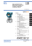
EJX910A and EJX930A
Fieldbus Communication Type
IM 01C25R03-01E
IM 01C25R03-01E
Yokogawa Electric Corporation
6th Edition
CONTENTS
CONTENTS
1.
INTRODUCTION ............................................................................................ 1-1
Regarding This Manual ................................................................................. 1-1
1.1 Safe Use of This Product .................................................................... 1-2
1.2 Warranty .............................................................................................. 1-3
1.3 ATEX Documentation .......................................................................... 1-3
2.
HANDLING CAUTIONS ................................................................................ 2-1
2.1
3.
Installation of an Explosion-Protected Instrument .............................. 2-1
2.1.1 FM approval ................................................................................ 2-1
2.1.2 CSA Certification ......................................................................... 2-4
2.1.3 CENELEC ATEX Certification ..................................................... 2-5
2.1.4 IECEx Certification ...................................................................... 2-9
ABOUT FIELDBUS ....................................................................................... 3-1
3.1
3.2
Outline ................................................................................................. 3-1
Internal Structure of EJX Multivariable Transmitter ............................ 3-1
3.2.1 System/network Management VFD ............................................ 3-1
3.2.2 Function Block VFD .................................................................... 3-1
3.3 Logical Structure of Each Block .......................................................... 3-2
3.4 Wiring System Configuration .............................................................. 3-2
4.
GETTING STARTED ..................................................................................... 4-1
4.1
4.2
4.3
4.4
4.5
4.6
4.7
5.
Connection of Devices ........................................................................ 4-1
Host Setting ......................................................................................... 4-2
Bus Power ON .................................................................................... 4-3
Integration of DD ................................................................................. 4-3
Reading the Parameters ..................................................................... 4-3
Continuous Record of Values ............................................................. 4-4
Generation of Alarm ............................................................................ 4-4
CONFIGURATION ......................................................................................... 5-1
5.1
5.2
5.3
5.4
5.5
Network Design ................................................................................... 5-1
Network Definition ............................................................................... 5-1
Definition of Combining Function Blocks ............................................ 5-2
Setting of Tags and Addresses .......................................................... 5-3
Communication Setting ....................................................................... 5-4
5.5.1 VCR Setting ................................................................................. 5-4
5.5.2 Function Block Execution Control ............................................... 5-5
5.6 Block Setting ....................................................................................... 5-5
5.6.1 Link Object .................................................................................. 5-5
5.6.2 Trend Object ................................................................................ 5-6
5.6.3 View Object ................................................................................. 5-6
5.6.4 Function Block Parameters ....................................................... 5-13
FD No. IM 01C25R03-01E
6th Edition: Aug. 2009(KP)
All Rights Reserved, Copyright © 2006, Yokogawa Electric Corporation
i
IM 01C25R03-01E
CONTENTS
6.
EXPLANATION OF BASIC ITEMS............................................................... 6-1
6.1
6.2
6.3
Outline ................................................................................................. 6-1
Setting and Changing Parameters for the Whole Process ................ 6-1
SENSOR Transducer Block ................................................................ 6-1
6.3.1 Functional block .......................................................................... 6-2
6.3.2 Block Mode .................................................................................. 6-2
6.3.3 Functions Relating to Differential Pressure ................................ 6-2
6.3.4 Functions Relating to Static Pressure ......................................... 6-4
6.3.5 Functions Relating to External Temperature .............................. 6-4
6.3.6 Simulation Function ..................................................................... 6-5
6.3.7 Functions Relating to Capsule and Amplifier Temperature ........ 6-6
6.3.8 Functions Relating to Flange Temperature (option code: /DG1) 6-6
6.3.9 BLOCK_ERR ............................................................................... 6-6
6.3.10 XD_ERROR ................................................................................. 6-6
6.4 FLOW Transducer Block ..................................................................... 6-7
6.4.1 Outline of the Functions .............................................................. 6-7
6.4.2 Block Mode .................................................................................. 6-7
6.4.3 Calculation of the Flow ................................................................ 6-7
6.4.4 Flow Unit/Decimal Point Digit ...................................................... 6-7
6.4.5 Flow Type Selection .................................................................... 6-7
6.4.6 BLOCK_ERR ............................................................................... 6-8
6.4.7 XD_ERROR ................................................................................. 6-8
6.5 LCD Transducer Block ........................................................................ 6-8
6.5.1 Outline of the Functions .............................................................. 6-8
6.5.2 Block Mode .................................................................................. 6-8
6.5.3 Display Contents of the integral indicator ................................... 6-8
6.5.4 Example Displays of the integral indicator.................................. 6-9
6.5.5 Procedure to Set the Built-in Display ........................................ 6-10
6.5.6 Units That Can Be Displayed on the LCD by the Automatic
Link Function ............................................................................. 6-12
6.6 AI Function Block .............................................................................. 6-14
6.6.1 Function Blocks ......................................................................... 6-14
6.6.2 Block Mode ................................................................................ 6-14
6.6.3 IO_OPTS ................................................................................... 6-14
6.6.4 STATUS_OPT ........................................................................... 6-14
6.6.5 OUT_D ...................................................................................... 6-14
6.6.6 Basic Parameters of the AI Block ............................................. 6-15
7.
IN-PROCESS OPERATION .......................................................................... 7-1
7.1
7.2
Mode Transition .................................................................................. 7-1
Generation of Alarm ............................................................................ 7-1
7.2.1 Indication of Alarm ...................................................................... 7-1
7.2.2 Alarms and Events ...................................................................... 7-1
7.3 Simulation Function ............................................................................. 7-2
8.
DEVICE INFORMATION ............................................................................... 8-1
8.1
8.2
DEVICE STATUS ................................................................................ 8-1
Status of each parameter in failure mode .......................................... 8-5
ii
IM 01C25R03-01E
CONTENTS
9.
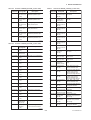
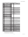
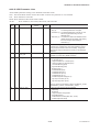
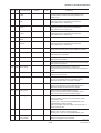
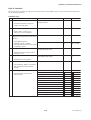
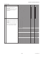
PARAMETER LISTS ..................................................................................... 9-1
9.1
9.2
9.3
9.4
9.5
9.6
Resource Block ................................................................................... 9-1
SENSOR Transducer Block ................................................................ 9-3
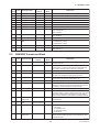
FLOW Transducer Block ..................................................................... 9-8
LCD Transducer Block ...................................................................... 9-11
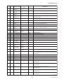
Al Function Block .............................................................................. 9-15
Parameter Names Cross Reference ................................................. 9-17
10. GENERAL SPECIFICATIONS .................................................................... 10-1
10.1 Standard specifications ..................................................................... 10-1
10.2 Optional specifications ...................................................................... 10-1
10.3 Optional specifications (For Explosion Protected type) .................... 10-2
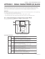
APPENDIX 1. SIGNAL CHARACTERIZER (SC) BLOCK................................ A-1
A1.1 Schematic Diagram of Signal Characterizer Block ............................. A-1
A1.2 Input Section ....................................................................................... A-3
A1.2.1 Determining the Mode ................................................................. A-3
A1.2.2 Judging BLOCK_ERR ................................................................. A-3
A1.3 Line-segment Factor Determination Section ....................................... A-4
A1.3.1 Conditions for Configuring Valid Coefficients
(CURVE_X, CURVE_Y) .............................................................. A-4
A1.4 List of Signal Characterizer Block Parameters ................................... A-6
A1.5 Application Example ............................................................................ A-7
A1.5.1 Input Compensation .................................................................... A-7
A1.5.2 Calorie Flow Compensation ........................................................ A-7
A1.5.3 Backward Control ........................................................................ A-7
APPENDIX 2. INTEGRATOR (IT) BLOCK ....................................................... A-9
A2.1 Schematic Diagram of Integrator Block .............................................. A-9
A2.2 Input Process Section ....................................................................... A-10
A2.2.1 Determining Input Value Statuses ............................................ A-10
A2.2.2 Converting the Rate .................................................................. A-10
A2.2.3 Converting Accumulation .......................................................... A-11
A2.2.4 Determining the Input Flow Direction ........................................ A-11
A2.3 Adder ................................................................................................. A-12
A2.3.1 Status of Value after Addition ................................................... A-12
A2.3.2 Addition ...................................................................................... A-12
A2.4 Integrator ........................................................................................... A-13
A2.5 Output Process ................................................................................. A-14
A2.5.1 Status Determination ................................................................. A-14
A2.5.2 Determining the Output Value................................................... A-15
A2.5.3 Mode Handling .......................................................................... A-16
A2.6 Reset ................................................................................................. A-17
A2.6.1 Reset Trigger ............................................................................. A-17
A2.6.2 Reset Timing ............................................................................. A-17
A2.6.3 Reset Process ........................................................................... A-18
A2.7 List of Integrator Block Parameters .................................................. A-19
iii
IM 01C25R03-01E
CONTENTS
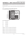
APPENDIX 3. INPUT SELECTOR (IS) BLOCK .............................................. A-21
A3.1 Input Selector Function Block Schematic ......................................... A-21
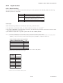
A3.2 Input Section .................................................................................... A-23
A3.2.1 Mode Handling .......................................................................... A-23
A3.2.2 MIN_GOOD Handling................................................................ A-24
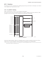
A3.3 Selection ........................................................................................... A-25
A3.3.1 OP_SELECT Handling .............................................................. A-25
A3.3.2 SELECTION Handling ............................................................... A-26
A3.4 Output Processing ............................................................................ A-32
A3.4.1 Handling of SELECTED ............................................................ A-32
A3.4.2 OUT Processing ........................................................................ A-33
A3.4.3 STATUS_OPTS ......................................................................... A-34
A3.5 List of Input Selector Block Parameters ........................................... A-34
A3.6 Application Example .......................................................................... A-35
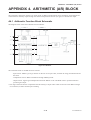
APPENDIX 4. ARITHMETIC (AR) BLOCK ...................................................... A-36
A4.1 Arithmetic Function Block Schematic ............................................... A-36
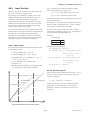
A4.2 Input Section .................................................................................... A-37
A4.2.1 Main Inputs ................................................................................ A-37
A4.2.2 Auxiliary Inputs .......................................................................... A-37
A4.2.3 INPUT_OPTS ............................................................................ A-38
A4.2.4 Relationship between the Main Inputs and PV......................... A-38
A4.3 Computation Section ......................................................................... A-39
A4.3.1 Computing Equations ................................................................ A-39
A4.3.2 Compensated Values ................................................................ A-39
A4.3.3 Average Calculation .................................................................. A-39
A4.4 Output Section .................................................................................. A-39
A4.4.1 Mode Handling .......................................................................... A-40
A4.4.2 Status Handling ......................................................................... A-40
A4.5 List of the Arithmetic Block Parameters .......................................... A-41
APPENDIX 5. PID BLOCK .............................................................................. A-43
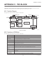
A5.1 Function Diagram .............................................................................. A-43
A5.2 Functions of PID Block ..................................................................... A-43
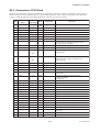
A5.3 Parameters of PID Block .................................................................. A-44
A5.4 PID Computation Details ................................................................... A-46
A5.4.1 PV-proportional and -derivative Type PID (I-PD) Control
Algorithm ................................................................................... A-46
A5.4.2 PID Control Parameters ............................................................ A-46
A5.5 Control Output ................................................................................... A-46
A5.5.1 Velocity Type Output Action...................................................... A-46
A5.6 Direction of Control Action ................................................................ A-46
A5.7 Control Action Bypass ....................................................................... A-46
A5.8 Feed-forward ..................................................................................... A-47
A5.9 Block Modes ...................................................................................... A-47
A5.9.1 Mode Transitions ....................................................................... A-47
A5.10 Bumpless Transfer ............................................................................ A-48
A5.11 Setpoint Limiters ............................................................................... A-48
A5.11.1When PID Block Is in Auto Mode ............................................. A-48
A5.11.2When PID Block Is in Cas or RCas Mode................................ A-48
A5.12 External-output Tracking ................................................................... A-48
A5.13 Measured-value Tracking .................................................................. A-48
iv
IM 01C25R03-01E
CONTENTS
A5.14 Initialization and Manual Fallback (IMan) ......................................... A-49
A5.15 Manual Fallback ................................................................................ A-49
A5.16 Auto Fallback .................................................................................... A-49
A5.17 Mode Shedding upon Computer Failure ........................................... A-50
A5.17.1SHED_OPT ............................................................................... A-50
A5.18 Alarms ............................................................................................... A-50
A5.18.1Block Alarm (BLOCK_ALM) ...................................................... A-50
A5.18.2Process Alarms ......................................................................... A-50
A5.19 Example of Block Connections ......................................................... A-51
A5.20 View Object for PID Function Block ................................................. A-51
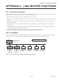
APPENDIX 6. LINK MASTER FUNCTIONS ................................................... A-53
A6.1 Link Active Scheduler ....................................................................... A-53
A6.2 Link Master ........................................................................................ A-53
A6.3 Transfer of LAS ................................................................................. A-54
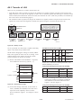
A6.4 LM Functions ..................................................................................... A-55
A6.5 LM Parameters .................................................................................. A-56
A6.5.1 LM Parameter List ..................................................................... A-56
A6.5.2 Descriptions for LM Parameters ............................................... A-58
A6.6 FAQs ................................................................................................. A-60
APPENDIX 7. SOFTWARE DOWNLOAD ....................................................... A-61
A7.1
A7.2
A7.3
A7.4
A7.5
A7.6
A7.7
A7.8
A7.9
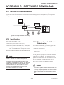
Benefits of Software Download ......................................................... A-61
Specifications .................................................................................... A-61
Preparations for Software Downloading ........................................... A-61
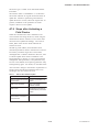
Software Download Sequence .......................................................... A-62
Download Files .................................................................................. A-62
Steps after Activating a Field Device ................................................ A-63
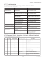
Troubleshooting ................................................................................. A-64
Resource Block’s Parameters Relating to Software Download ....... A-64
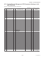
System/Network Management VFD Parameters Relating to
Software Download ........................................................................... A-66
A7.10 Comments on System/Network Management VFD Parameters
Relating to Software Download ........................................................ A-67
APPENDIX 8. ADVANCED DIAGNOSTICS ................................................... A-69
A8.1 Multi-sensing Process Monitoring ..................................................... A-69
A8.2 Impulse Line Blockage Detection (ILBD) .......................................... A-69
A8.2.1 Blockage Detection ................................................................... A-71
A8.2.2 Combination of Reference Result and Blockage Detection ...... A-72
A8.2.3 Operating Parameters ................................................................ A-73
A8.2.4 Operating Procedure .................................................................. A-74
A8.2.5 Alarm and Alert setting ............................................................... A-76
A8.2.6 Condition Check ......................................................................... A-78
A8.2.7 Obtain Reference Values ........................................................... A-79
A8.2.8 Capability Test of Blockage Detection Operation ...................... A-80
A8.2.9 Start ILBD Operation .................................................................. A-80
A8.2.10 Tuning ....................................................................................... A-81
A8.2.11 Reset of Reference Value ........................................................ A-82
A8.2.12 ILBD Parameter Lists ............................................................... A-83
A8.2.13 Checklist ................................................................................... A-86
v
IM 01C25R03-01E
CONTENTS
A8.3 Heat Trace Monitoring ....................................................................... A-91
A8.3.1 FLG_TEMP_COEF Setting ........................................................ A-91
A8.3.2 Alert and Alarm Setting ............................................................. A-92
A8.3.3 Assignment of FLG_TEMP_VAL to Process Value (PV)
in AI function block .................................................................... A-92
A8.3.4 Analog Alert ................................................................................ A-92
A8.3.5 Out of Temperature Measurement Range ................................. A-92
A8.3.6 Status Error ................................................................................ A-92
A8.3.7 Parameter Lists for Heat Trace Monitoring function .................. A-93
REVISION RECORD
vi
IM 01C25R03-01E
1. INTRODUCTION
1.
INTRODUCTION
This manual is for the DPharp EJX Multivariable
Transmitter Fieldbus Communication Type. The
Fieldbus communication type is based on the same
silicon resonant sensing technology used in the HART
communication type, and is similar to the communication types in terms of basic performance and operation.
This manual describes only those topics that are
required for operation of the Fieldbus communication
type. For information on the installation, wiring, and
maintenance of EJX series pressure transmitters, refer
to the user’s manual for each model.
WARNING
Indicates a potentially hazardous situation which,
if not avoided, could result in death or serious
injury.
CAUTION
Indicates a potentially hazardous situation which,
if not avoided, may result in minor or moderate
injury. It may also be used to alert against
unsafe practices.
Regarding This Manual
• This manual should be passed on to the end user.
• The contents of this manual are subject to change
without prior notice.
• All rights reserved. No part of this manual may be
reproduced in any form without Yokogawa’s written
permission.
IMPORTANT
Indicates that operating the hardware or software
in this manner may damage it or lead to system
failure.
• Yokogawa makes no warranty of any kind with
regard to this manual, including, but not limited to,
implied warranty of merchantability and fitness for a
particular purpose.
• If any question arises or errors are found, or if any
information is missing from this manual, please
inform the nearest Yokogawa sales office.
NOTE
Draws attention to information essential for
understanding the operation and features.
• The specifications covered by this manual are
limited to those for the standard type under the
specified model number break-down and do not
cover custom-made instruments.
• Please note that changes in the specifications,
construction, or component parts of the instrument
may not immediately be reflected in this manual at
the time of change, provided that postponement of
revisions will not cause difficulty to the user from a
functional or performance standpoint.
• The following safety symbols are used in this
manual:
1-1
IM 01C25R03-01E
1. INTRODUCTION
1.1
(c) Operation
• Wait 5 min. after the power is turned off, before
opening the covers.
Safe Use of This Product
For the safety of the operator and to protect the
instrument and the system, please be sure to follow this
manual’s safety instructions when handling this
instrument. If these instructions are not heeded, the
protection provided by this instrument may be impaired. In this case, Yokogawa cannot guarantee that
the instrument can be safely operated. Please pay
special attention to the following points:
(d) Maintenance
• Please carry out only the maintenance procedures
described in this manual. If you require further
assistance, please contact the nearest Yokogawa
office.
• Care should be taken to prevent the build up of dust
or other materials on the display glass and the name
plate. To clean these surfaces, use a soft, dry cloth.
(a) Installation
• This instrument may only be installed by an engineer or technician who has an expert knowledge of
this device. Operators are not allowed to carry out
installation unless they meet this condition.
(e) Explosion Protected Type Instrument
• Users of explosion proof instruments should refer
first to section 2.1 (Installation of an Explosion
Protected Instrument) of this manual.
• With high process temperatures, care must be taken
not to burn yourself by touching the instrument or
its casing.
• The use of this instrument is restricted to those who
have received appropriate training in the device.
• Never loosen the process connector nuts when the
instrument is installed in a process. This can lead to
a sudden, explosive release of process fluids.
• Take care not to create sparks when accessing the
instrument or peripheral devices in a hazardous
location.
• When draining condensate from the pressure
detector section, take appropriate precautions to
prevent the inhalation of harmful vapors and the
contact of toxic process fluids with the skin or eyes.
(f) Modification
• Yokogawa will not be liable for malfunctions or
damage resulting from any modification made to this
instrument by the customer.
• When removing the instrument from a hazardous
process, avoid contact with the fluid and the interior
of the meter.
• All installation work shall comply with local
installation requirements and the local electrical
code.
(b) Wiring
• The instrument must be installed by an engineer or
technician who has an expert knowledge of this
instrument. Operators are not permitted to carry out
wiring unless they meet this condition.
• Before connecting the power cables, please confirm
that there is no current flowing through the cables
and that the power supply to the instrument is
switched off.
1-2
IM 01C25R03-01E
1. INTRODUCTION
1.2
Warranty
1.3
• The warranty shall cover the period noted on the
quotation presented to the purchaser at the time of
purchase. Problems occurring during the warranty
period shall basically be repaired free of charge.
ATEX Documentation
This is only applicable to the countries in European
Union.
GB
• If any problems are experienced with this instrument, the customer should contact the Yokogawa
representative from which this instrument was
purchased or the nearest Yokogawa office.
All instruction manuals for ATEX Ex related products
are available in English, German and French. Should
you require Ex related instructions in your local
language, you are to contact your nearest Yokogawa
office or representative.
• If a problem arises with this instrument, please
inform us of the nature of the problem and the
circumstances under which it developed, including
the model specification and serial number. Any
diagrams, data and other information you can
include in your communication will also be helpful.
DK
Alle brugervejledninger for produkter relateret til
ATEX Ex er tilgængelige på engelsk, tysk og fransk.
Skulle De ønske yderligere oplysninger om håndtering
af Ex produkter på eget sprog, kan De rette
henvendelse herom til den nærmeste Yokogawa
afdeling eller forhandler.
• The party responsible for the cost of fixing the
problem shall be determined by Yokogawa following an investigation conducted by Yokogawa.
• The purchaser shall bear the responsibility for repair
costs, even during the warranty period, if the
malfunction is due to:
I
Tutti i manuali operativi di prodotti ATEX
contrassegnati con Ex sono disponibili in inglese,
tedesco e francese. Se si desidera ricevere i manuali
operativi di prodotti Ex in lingua locale, mettersi in
contatto con l’ufficio Yokogawa più vicino o con un
rappresentante.
- Improper and/or inadequate maintenance by the
purchaser.
- Malfunction or damage due to a failure to handle,
use, or store the instrument in accordance with the
design specifications.
- Use of the product in question in a location not
conforming to the standards specified by
Yokogawa, or due to improper maintenance of the
installation location.
- Failure or damage due to modification or repair by
any party except Yokogawa or an approved
representative of Yokogawa.
- Malfunction or damage from improper relocation
of the product in question after delivery.
- Reason of force majeure such as fires, earthquakes,
storms/floods, thunder/lightening, or other natural
disasters, or disturbances, riots, warfare, or
radioactive contamination.
E
Todos los manuales de instrucciones para los productos
antiexplosivos de ATEX están disponibles en inglés,
alemán y francés. Si desea solicitar las instrucciones de
estos artículos antiexplosivos en su idioma local,
deberá ponerse en contacto con la oficina o el
representante de Yokogawa más cercano.
NL
Alle handleidingen voor producten die te maken
hebben met ATEX explosiebeveiliging (Ex) zijn
verkrijgbaar in het Engels, Duits en Frans. Neem,
indien u aanwijzingen op het gebied van
explosiebeveiliging nodig hebt in uw eigen taal, contact
op met de dichtstbijzijnde vestiging van Yokogawa of
met een vertegenwoordiger.
1-3
IM 01C25R03-01E
1. INTRODUCTION
SF
SK
Kaikkien ATEX Ex -tyyppisten tuotteiden käyttöhjeet
ovat saatavilla englannin-, saksan- ja ranskankielisinä.
Mikäli tarvitsette Ex -tyyppisten tuotteiden ohjeita
omalla paikallisella kielellännne, ottakaa yhteyttä
lähimpään Yokogawa-toimistoon tai -edustajaan.
CZ
P
Todos os manuais de instruções referentes aos
produtos Ex da ATEX estão disponíveis em Inglês,
Alemão e Francês. Se necessitar de instruções na sua
língua relacionadas com produtos Ex, deverá entrar em
contacto com a delegação mais próxima ou com um
representante da Yokogawa.
F
LT
Tous les manuels d’instruction des produits ATEX Ex
sont disponibles en langue anglaise, allemande et
française. Si vous nécessitez des instructions relatives
aux produits Ex dans votre langue, veuillez bien
contacter votre représentant Yokogawa le plus proche.
D
LV
Alle Betriebsanleitungen für ATEX Ex bezogene
Produkte stehen in den Sprachen Englisch, Deutsch
und Französisch zur Verfügung. Sollten Sie die
Betriebsanleitungen für Ex-Produkte in Ihrer
Landessprache benötigen, setzen Sie sich bitte mit
Ihrem örtlichen Yokogawa-Vertreter in Verbindung.
S
EST
Alla instruktionsböcker för ATEX Ex
(explosionssäkra) produkter är tillgängliga på
engelska, tyska och franska. Om Ni behöver
instruktioner för dessa explosionssäkra produkter på
annat språk, skall Ni kontakta närmaste
Yokogawakontor eller representant.
GR
ATEX Ex
, .
Ex Yokogawa .
1-4
IM 01C25R03-01E
1. INTRODUCTION
PL
SLO
H
BG
RO
M
1-5
IM 01C25R03-01E
2. HANDLING CAUTIONS
2.
HANDLING CAUTIONS
2.1 Installation of an ExplosionProtected Instrument
If a customer makes a repair or modification to an
intrinsically safe or explosionproof instrument and the
instrument is not restored to its original condition, its
intrinsically safe or explosionproof construction may
be compromised and the instrument may be hazardous
to operate. Please contact Yokogawa before making
any repair or modification to an instrument.
CAUTION
This instrument has been tested and certified as
being intrinsically safe or explosionproof. Please
note that severe restrictions apply to this
instrument’s construction, installation, external
wiring, maintenance and repair. A failure to
abide by these restrictions could make the
instrument a hazard to operate.
WARNING
Maintaining the safety of explosionproof equipment requires great care during mounting,
wiring, and piping. Safety requirements also
place restrictions on maintenance and repair.
Please read the following sections very carefully.
WARNING
The range setting switch must not be used in a
hazardous area.
2.1.1 FM approval
a. FM Explosionproof Type
Caution for FM Explosionproof type
Note 1. EJX multivariable transmitter with optional
code /FF1 is applicable for use in hazardous
locations:
• Applicable Standard: FM3600, FM3615,
FM3810, ANSI/NEMA 250
• Explosionproof for Class I, Division 1,
Groups B, C and D.
• Dust-ignitionproof for Class II/III, Division
1, Groups E, F and G.
• Enclosure rating: NEMA 4X.
• Temperature Class: T6
• Ambient Temperature: –40 to 60°C
• Supply Voltage: 32V dc max.
• Current Draw: 15 mA dc
Note 2. Wiring
• All wiring shall comply with National
Electrical Code ANSI/NFPA70 and Local
Electrical Codes.
• When installed in Division 1, “FACTORY
SEALED, CONDUIT SEAL NOT REQUIRED.”
Note 3. Operation
• Keep the “WARNING” nameplate attached
to the transmitter.
WARNING: OPEN CIRCUIT BEFORE
REMOVING COVER. FACTORY
SEALED, CONDUIT SEAL NOT REQUIRED. INSTALL IN ACCORDANCE
WITH THE USERS MANUAL IM 01C25.
• Take care not to generate mechanical
sparking when accessing the instrument and
peripheral devices in a hazardous location.
Note 4. Maintenance and Repair
• The instrument modification or parts
replacement by other than authorized
representative of Yokogawa Electric Corporation is prohibited and will void Factory
Mutual Explosionproof Approval.
2-1
IM 01C25R03-01E
2. HANDLING CAUTIONS
b. FM Intrinsically safe and Nonincendive Type
EJX multivariable transmitter with optional code /
FS15.
• Applicable standard: FM3600, FM3610, FM3611,
FM3810, ANSI/NEMA250, IEC60079-27
• FM Intrinsically Safe Approval
[Entity Model]
Class I, II & III, Division 1, Groups A, B, C, D, F
& G, Temperature Class T4 Ta=60°C, Type 4X and
Class I, Zone 0, AEx ia IIC, Temperature Class T4
Ta=60°C, Type 4X
[FISCO Model]
Class I, II & III, Division 1, Groups A, B, C, D, F
& G, Temperature Class T4 Ta=60°C, Type 4X and
Class I, Zone 0, AEx ia IIC, Temperature Class T4
Ta=60°C, Type 4X
• Nonincendive Approval
Class I, Division 2, Groups A, B, C & D
Temperature Class T4 Ta=60°C, Type 4X and
Class II, Division 2, Groups F & G Temperature
Class T4 Ta=60°C, Type 4X and Class I, Zone 2,
Group IIC, Temperature Class T4 Ta=60°C, Type
4X and Class III, Division 1, Temperature Class T4
Ta=60°C, Type 4X
• Electrical Connection: 1/2 NPT female, M20
female
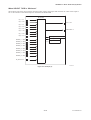
• Caution for FM Intrinsically safe type. (Following
contents refer to “DOC. No. IFM026-A12
p.1 to p.4.”)
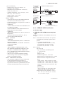
IFM026-A12
Installation Diagram for Intrinsically safe
(Division 1 Installation)
Terminator
Pressure
Transmitter
Field Instruments
Field Instruments
Hazardous Location
Non-Hazardous Location
Terminator
Safety Barrier
Note 3. Installation should be in accordance with
ANSI/ISA 12.06.01 “Installation of Intrinsi
cally Safe Systems for Hazardous (Classified)
Locations” and the National Electrical Code
(ANSI/NFPA 70) Sections 504 and 505.
Note 4. The configuration of Associated Apparatus
must be Factory Mutual Research Approved
under FISCO Concept.
Note 5. Associated Apparatus manufacturer’s installa
tion drawing must be followed when installing
this equipment.
Note 6. No revision to drawing without prior Factory
Mutual Research Approval.
Note 7. Terminator must be FM Approved.
Note 8. Note a warning label worded "SUBSTITU
TION OF COMPONENTS MAY IMPAIR
INTRINSIC SAFETY", and "INSTALL IN
ACCORDANCE DOC.NO.IFM026-A12 P.1
TO 4."
Electrical Data:
• Rating 1 (Entity)
For Groups A, B, C, D, F, and G or Group
IIC
Maximum Input Voltage Vmax: 24 V
Maximum Input Current Imax: 250 mA
Maximum Input Power Pmax: 1.2 W
Maximum Internal Capacitance Ci: 3.52 nF
Maximum Internal Inductance Li: 0 mH
or
• Rating 2 (FISCO)
For Groups A, B, C, D, F, and G or Group
IIC
Maximum Input Voltage Vmax: 17.5 V
Maximum Input Current Imax: 380 mA
Maximum Input Power Pmax: 5.32 W
Maximum Internal Capacitance Ci: 3.52 nF
Maximum Internal Inductance Li: 0 mH
or
• Rating 3 (FISCO)
For Groups C, D, F, and G or Group IIB
Maximum Input Voltage Vmax: 17.5 V
Maximum Input Current Imax: 460 mA
Maximum Input Power Pmax: 5.32 W
Maximum Internal Capacitance Ci: 3.52 nF
Maximum Internal Inductance Li: 0 mH
Sensor Circuit: Uo=6.51 V, Io=4 mA, Po=6 mW,
Co=34 µF, Lo=500 mH
F0206.EPS
Note 1. Barrier must be installed in an enclosure that
meets the requirements of ANSI/ISA 61010-1.
Note 2. Control equipment connected to the Associ
ated Apparatus must not use or generate more
than 250 Vrms or Vdc.
Note: In the rating 1, the output current of the barrier must be
limited by a resistor “Ra” such that Io=Uo/Ra. In the rating
2 or 3, the output characteristics of the barrier must be the
type of trapezoid which are certified as the FISCO model
(See “FISCO Rules”). The safety barrier may include a
terminator. More than one field instruments may be
connected to the power supply line.
2-2
IM 01C25R03-01E
2. HANDLING CAUTIONS
FISCO Rules
The FISCO Concept allows the interconnection of
intrinsincally safe apparatus to associated apparatus not
specifically examined in such combination. The
criterion for such interconnection is that the voltage
(Ui), the current (Ii) and the power (Pi) which intrinsically safe apparatus can receive and remain intrinsically safe, considering faults, must be equal or greater
than the voltage (Uo, Voc, Vt), the current (Io, Isc, It)
and the power (Po) which can be provided by the
associated apparatus (supply unit).
Po Pi, Uo Ui, Io Ii
In addition, the maximum unprotected residual capacitance (Ci) and inductance (Li) of each apparatus (other
than the terminators) connected to the fieldbus must be
less than or equal to 5 nF and 10 H respectively.
Terminators
At each end of the trunk cable an FM approved line
terminator with the following parameters is suitable:
R = 90...100 Ω
C = 0...2.2 mF
System evaluations
The number of passive device like transmitters,
actuators, hand held terminals connected to a single
bus segment is not limited due to I.S. reasons. Furthermore, if the above rules are respected, the inductance
and capacitance of the cable need not to be considered
and will not impair the intrinsic safety of the installation.
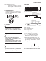
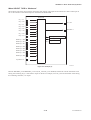
HAZARDOUS AREA
Ci 5nF, Li 10H
In each I.S. fieldbus segment only one active source,
normally the associated apparatus, is allowed to
provide the necessary power for the fieldbus system.
The allowed voltage(Uo, Voc,Vt) of the associated
apparatus used to supply the bus cable must be limited
to the range of 14 V dc to 17.5 V dc. All other
equipment connected to the bus cable has to be
passive, meaning that the apparatus is not allowed to
provide energy to the system, except to a leakage
current of 50 A for each connected device.
SAFE AREA
Supply Unit and
Safety Barrier
(FISCO Model)
Terminator
(FISCO Model)
Ex i
U
U
I
HandheldTerminal
Terminator
Data
Field Instruments
(Passive)
F0207.EPS
Supply unit
Trapezoidal or rectangular output characteristic only
Uo = 14...17.5 V (I.S. maximum value)
Io according to spark test result or other assessment.
No specification of Lo and Co is required on the
certificate or label.
I.S. fieldbus system complying with FISCO model
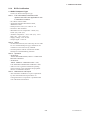
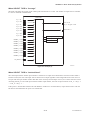
Installation Diagram for Nonincendive
(Division 2 Installation)
Terminator
Cable
The cable used to interconnect the devices needs to
comply with the following parameters:
Loop resistance R': 15...150 Ω/km
Inductance per unit length L': 0.4...1 mH/km
Capacitance per unit length C': 45...200 nF/km.
C'=C' line/line + 0.5 C' line/screen, if both lines are
floating or C'=C' line/line + C' line/screen, if the
screen is connected to one line.
Length of spur cable: max. 60 m
Length of trunk cable: max. 1 km (Group IIC) or 5
km (Group IIB)
Length of splice : max.1m
SUPPLY
Pressure
Transmitter
Transmitter
Transmitter
Hazardous location
Non-Hazardous location
Terminator
General Purpose
Equipment
FM Approved
Associated Nonincendive Field
Wiring Apparatus
Vt or Voc
It or Isc
Ca
La
F0208.EPS
2-3
IM 01C25R03-01E
2. HANDLING CAUTIONS
Note 1. Installation should be in accordance with the
National Electrical Code ® (ANSI/NFPA 70)
Article 500.
Note 2. The configuration of Associated Nonincendive
Field Wiring Apparatus must be FM
Approved.
Note 3. Approved under FNICO Concept.
Note 4. Dust-tight conduit seal must be used when
installed in Class II and Class III environments.
Note 5. Associated Apparatus manufacturer’s installation drawing must be followed when installing
this apparatus.
Note 6. No revision to drawing without prior FM
Approvals.
Note 7. Terminator must be FM Approved.
Note 8. The nonincendive field wiring circuit concept
allows interconection of nonincendive field
wiring apparatus with associated nonincendive
field wiring apparatus, using any of the wiring
methods permitted for unclassified locations.
Note 9. Installation requirements;
Vmax Voc or Vt
Imax = see note 10.
Ca Ci + Ccable
La Li + Lcable
Note 10. For this current controlled circuit, the parameter (Imax) is not required and need not be
aligned with parameter (Isc) of the barrier or
associated nonincendive field wiring apparatus.
Note 11. If ordinary location wiring methods are used,
the transmitter shall be connected to FM
Approved associated non-incendive field
wiring apparatus.
In each N.I. Fieldbus segment only one active source,
normally the associated nonincendive field wiring
apparatus, is allowed to provide the necessary power
for the Fieldbus system. The allowed voltage (Uo, Voc
or Vt) of the associated nonincendive field wiring
apparatus used to supply the bus cable must be limited
to the range 14Vdc to 17.5Vdc. All other equipment
connected to the bus cable has to be passive, meaning
that the apparatus is not allowed to provide energy to
the system, except a leakage current of 50 µA for each
connected device. Separately powered equipment needs
galvanic isolation to ensure the nonincendive field
wiring Fieldbus circuit remains passive.
Electrical data:
Vmax: 32V
Ci:1.76 nF
Li: 0 H
2.1.2 CSA Certification
FNICO Rules
The FNICO Concept allows the interconnection of
nonincendive field wiring apparatus to associated
nonincendive field wiring apparatus not specifically
examined in such combination. The criterion for such
interconnection is that the voltage (Vmax), the current
(Imax) and the power (Pmax) which nonincendive field
wiring apparatus can receive and remain nonincendive,
considering faults, must be equal or greater than the
voltage (Uo, Voc or Vt), the current (Io, Isc or It) and
the power (Po) which can be provided by the associated nonincendive field wiring apparatus (supply unit).
In addition the maximum unprotected residual capacitance (Ci) and inductance (Li) of each apparatus (other
than terminators) connected to the Fieldbus must be
less than or equal to 5nF and 20uH respectively.
Cable
The cable used to interconnect the devices needs to
comply with the following parameters:
Loop resistance R': 15...150 Ω/km
Inductance per unit length L': 0.4...1 mH/km
Capacitance per unit length C': 45....200 nF/km
C' =C' line/line+0.5 C' line/screen, if both lines are
floating or C' = C' line/line + C'line/screen, if
the screen is connected to one line.
Length of spur cable: max. 60 m
Length of trunk cable: max. 1 km (Group IIC) or
5 km (Group IIB)
Length of splice: max = 1 m
Terminators
At the end of each trunk cable an FM Approved line
terminator with the following parameters is suitable:
R= 90...100 Ω
C = 0 ....2.2 uF
a. CSA Explosionproof Type
Caution for CSA explosionproof type.
Note 1. EJX multivariable transmitter with
optional code /CF1 is applicable for use
in hazardous locations:
Certificate: 2014354
• Applicable Standard: C22.2 No.0, C22.2 No.0.4,
C22.2 No.0.5, C22.2 No.25, C22.2 No.30,
C22.2 No.94, C22.2 No.61010.1-01, C22.2
No.60079-0, C22.2 No.60079-1
[For CSA C22.2]
• Explosion-proof for Class I, Groups B, C and D.
• Dustignition-proof for Class II/III, Groups E, F and
G.
• Enclosure: TYPE 4X
• Temperature Code: T6...T4
2-4
IM 01C25R03-01E
2. HANDLING CAUTIONS
Note 2. Wiring
• All wiring shall comply with Canadian Electrical
Code Part I and Local Electrical Codes.
• In hazardous location, wiring shall be in conduit as
shown in the figure.
• WARNING:
A SEAL SHALL BE INSTALLED WITHIN 50cm
OF THE ENCLOSURE.
UN SCELLEMENT DOIT ÊTRE INSTALLÉ À
MOINS DE 50cm DU BOÎTIER.
• WARNING:
WHEN INSTALLED IN CL.I, DIV 2, SEAL NOT
REQUIRED.
UNE FOIS INSTALLÉ DANS CL I, DIV 2,
AUCUN JOINT N'EST REQUIS.
Note 3. Operation
• WARNING:
AFTER DE-ENERGIZING, DELAY 5 MINUTES
BEFORE OPENING.
APRÉS POWER-OFF, ATTENDRE 5 MINUTES
AVANT D'OUVRIR.
• WARNING:
WHEN AMBIENT TEMPERATURE ≥ 65°C,
USE THE HEAT-RESISTING CABLES ≥ 90°C.
QUAND LA TEMPÉRATURE AMBIANTE ≥
65°C, UTILISEZ DES CÂBLES RÉSISTANTES Á
LA CHALEUR ≥ 90°C.
• Take care not to generate mechanical sparking
when accessing to the instrument and peripheral
devices in a hazardous location.
Note 4. Maintenance and Repair
• The instrument modification or parts replacement
by other than authorized representative of
Yokogawa Electric Corporation and Yokogawa
Corporation of America is prohibited and will void
Canadian Standards Explosionproof Certification.
Hazardous Locations Division 1
50 cm Max.
PULSE
PULSE
Non-Hazardous
Locations
Non-hazardous
Location
Equipment
32 V DC Max.
15 mA DC
Signal
Non-Hazardous
Locations
Non-hazardous
Location
Equipment
SUPP
LY
Conduit
Sealing Fitting
Multivariable Transmitter
CHECK
CHECK
ALARM
ALARM
Hazardous Locations Division 2
PULSE
[For CSA E60079]
• Flameproof for Zone 1, Ex d IIC T6...T4
• Enclosure: IP66 and IP67
• Maximum Process Temperature: 120°C (T4),
100°C (T5), 85°C (T6)
• Ambient Temperature: –50 to 75°C (T4), –50 to
80°C (T5), –50 to 72°C (T6)
• Supply Voltage: 32 V dc max.
• Output Signal: 15 mA dc
32 V DC Max.
15 mA DC
Signal
SUPP
LY
CHECK
CHECK
ALARM
ALARM
Sealing Fitting
Multivariable Transmitter
F0205E.EPS
2.1.3
CENELEC ATEX Certification
(1) Technical Data
a. CENELEC ATEX (KEMA) Intrinsically Safe
Type
Caution for CENELEC ATEX (KEMA) Intrinsically
safe type.
Note 1. EJX multivariable transmitter with optional
code /KS25 for potentially explosive atmospheres:
• No. KEMA 06ATEX0278 X
• Applicable Standard: EN 60079-0:2006,
EN 50020:2002, EN 60079-27:2006,
EN 50284:1999, EN 50281-1-1:1998
Note 2. Ratings
[Ex ia IIC T4]
Type of Protection and Marking Code:
Ex ia IIC T4
Group: II
Category: 1GD
Ambient Temperature: –40 to 60°C
Maximum Process Temperature (Tp.): 120°C
Maximum Surface Temperature for dust
proof.
T85°C (Tamb.: –40°C to 60°C, Tp.: 80°C)
T100°C (Tamb.: –40°C to 60°C, Tp.: 100°C)
T120°C (Tamb.: –40°C to 60°C, Tp.: 120°C)
Degree of Protection of the Enclosure: IP66
and IP67
Electrical Data
• When combined with Trapezoidal output
characteristic FISCO model IIC barrier
[Supply/Output circuit (terminals + and -)]
Ui = 17.5 V, Ii = 380 mA, Pi = 5.32 W,
Ci = 1.76 nF, Li = 0 H
2-5
IM 01C25R03-01E
2. HANDLING CAUTIONS
[Temperature sensor circuit]
Uo = 7.63 V, Io = 3.85 mA, Po = 8 mW,
Co = 4.8 F, Lo = 100 mH
• When combined with Linear characteristic
barrier
[Supply/Output circuit (terminals + and -)]
Ui = 24.0 V, Ii = 250 mA, Pi = 1.2 W,
Ci = 1.76 nF, Li = 0 H
[Temperature sensor circuit]
Uo = 7.63 V, Io = 3.85 mA, Po = 8 mW,
Co = 4.8 F, Lo = 100 mH
[Ex ia IIB T4]
Type of Protection and Marking Code:
Ex ia IIB T4
Group: II
Category: 1GD
Ambient Temperature: –40 to 60°C
Maximum Process Temperature (Tp.): 120°C
Maximum Surface Temperature for dust
proof.
T85°C (Tamb.: –40°C to 60°C, Tp.: 80°C)
T100°C (Tamb.: –40°C to 60°C, Tp.: 100°C)
T120°C (Tamb.: –40°C to 60°C, Tp.: 120°C)
Degree of Protection of the Enclosure: IP66
and IP67
Electrical Data
• When combined with Trapezoidal output
characteristic FISCO model IIB barrier
[Supply/Output circuit (terminals + and -)]
Ui = 17.5 V, Ii = 460 mA, Pi = 5.32 W,
Ci = 1.76 nF, Li = 0 H
[Temperatura sensor circuit]
Uo = 7.63 V, Io = 3.85 mA, Po = 8 mW,
Co = 4.8 F, Lo = 100 mH
Note 3. Installation
• All wiring shall comply with local installation requirements. (Refer to the installation
diagram)
Note 4. Maintenance and Repair
• The instrument modification or parts
replacement by other than authorized
representative of Yokogawa Electric Corporation is prohibited and will void KEMA
Intrinsically safe Certification.
Note 5. Special Conditions for Safe Use
• In the case where the enclosure of the
Multivariable Transmitter is made of
aluminium, if it is mounted in an area where
the use of category 1 G apparatus is required, it must be installed such, that even in
the event of rare incidents, ignition sources
due to impact and friction sparks are
excluded.
Note 6. Installation instructions
• The test voltage for the isolation between the
intrincically safe supply/output circuit and
the frame of the apparatas for Multivariable
Transmitters that are provided with surge
protection is limited to 90 V, due to the
presence of the surge protection device only.
When used in a potentially explosive
atmosphere, requiring the use of apparatus of
equipment category 1D or 2D, certified
cable entry devices shall be used that are
suitable for the application and correctly
installed.
FISCO Model
Non-Hazardous
Locations
Hazardous Locations
Supply Unit and
Safety Barrier
(FISCO Model)
Terminator
(FISCO Model)
Ex i
U
U
I
Terminator
Data
HandheldTerminal
Field Instruments
(Passive)
F0201-1.EPS
I.S. fieldbus system complying with FISCO
The criterion for such interconnection is that the
voltage (Ui), the current (Ii) and the power (Pi), which
intrinsically safe apparatus can receive, must be equal
or greater than the voltage (Uo), the current (Io) and the
power (Po) which can be provided by the associated
apparatus (supply unit).
Po Pi, Uo Ui, Io Ii
In addition, the maximum unprotected residual capacitance (Ci) and inductance (Li) of each apparatus (other
than the terminators) connected to the fieldbus line
must be equal or less than 5 nF and 10 H respectively.
Ci 5 nF, Li 10H
Supply unit
The supply unit must be certified by a Notified body as
FISCO model and following trapezoidal or rectangular
output characteristic is used.
Uo = 14...17.5 V (I.S. maximum value)
Io based on spark test result or other assessment,
2-6
IM 01C25R03-01E
2. HANDLING CAUTIONS
No specification of Lo and Co is required on the
certificate or label.
Cable
The cable used to interconnect the devices needs to
comply with the following parameters:
Loop resistance Rc: 15...150 Ω/km
Inductance per unit length Lc: 0.4...1 mH/km
Capacitance per unit length Cc: 45...200 nF/km
Length of spur cable: max. 60 m (IIC and IIB)
Length of trunk cable: max. 1 km (IIC) or 5 km
(IIB)
Terminators
The terminator must be certified by a Notified body as
FISCO model and at each end of the trunk cable an
approved line terminator with the following parameters
is suitable:
R = 90 . . . 102 Ω
C = 0 . . . 2.2 F. (0.8...1.2 F is required in
operation)
The resistor must be infallible according to IEC 6007911.
Number of Devices
The number of devices (max. 32) possible on a
fieldbus link depends on factors such as the power
consumption of each device, the type of cable used,
use of repeaters, etc.
Entity Model
Non-Hazardous
Locations
Hazardous Locations
Supply Unit and
Safety Barrier
Terminator
Ex i
U
U
I
Terminator
Data
HandheldTerminal
Field Instruments
(Passive)
F0202-1.EPS
I.S. fieldbus system complying with Entity model
I.S. values Power supply-field device:
Po Pi, Uo Ui, Io Ii
Calculation of max. allowed cable length:
Ccable Co - ∑Ci - ∑Ci (Terminator)
Lcable Lo - ∑Li
Number of Devices
The number of devices (max. 32) possible on a
fieldbus link depends on factors such as the power
consumption of each device, the type of cable used,
use of repeaters, etc.
b. CENELEC ATEX (KEMA) Flameproof Type
Caution for CENELEC ATEX (KEMA) flameproof
type
Note 1. EJX multivariable transmitter with optional
code /KF21 for potentially explosive atmospheres:
• No. KEMA 07ATEX0109
• Applicable Standard: EN 60079-0:2006,
EN 60079-1:2004, EN 61241-0:2006,
EN 61241-1:2004
• Type of Protection and Marking Code:
Ex d IIC T6...T4, Ex tD A21 IP6x T85,
T100, T120
• Group: II
• Category: 2GD
• Temperature Class: T6, T5, and T4
• Enclosure: IP66 and IP67
• Ambient Temperature for gas-proof:
–50 to 75°C (T6), –50 to 80°C (T5), and
–50 to 75°C (T4)
• Maximum Process Temperature (Tp.) for
gas-proof:
85°C (T6), 100°C (T5), and 120°C (T4)
• Maximum Surface Temperature for dust-proof:
T85°C (Tamb.: –40 to 40°C, Tp.: 80°C)
T100°C (Tamb.: –40 to 60°C, Tp.: 100°C)
T120°C (Tamb.: –40 to 80°C, Tp.: 120°C)
Note 2. Electrical Data
• Supply voltage: 32 V dc max.
Output current: 15 mA dc
Note 3. Installation
• All wiring shall comply with local installation requirements.
• The cable entry devices shall be of a
certified flameproof type, suitable for the
conditions of use.
Note 4. Operation
• Keep the “WARNING” label attached to the
transmitter.
WARNING: AFTER DE-ENERGIZING,
DELAY 5 MINUTES BEFORE
OPENING. WHEN THE AMBIENT
TEMP.65°C, USE HEAT-RESISTING
CABLES90°C.
• Take care not to generate mechanical
sparking when accessing the instrument and
peripheral devices in hazardous location.
2-7
IM 01C25R03-01E
2. HANDLING CAUTIONS
Note 5. Maintenance and Repair
• The instrument modification or part replacement by other than an authorized representative of Yokogawa Electric Corporation is
prohibited and will void KEMA Flameproof
Certification.
(2) Electrical Connection
A mark indicating the electrical connection type is
stamped near the electrical connection port. These
marks are as follows.
(6) Name Plate
Name plate
CAL
RNG
MODEL
SUFFIX
SUPPLY
OUTPUT
MWP
STYLE
V DC
mA DC
NO.
Made in Japan
TOKYO 180-8750 JAPAN
: Refer to USER'S MANUAL.
Tag plate for flameproof type
No. KEMA 07ATEX0109
Ex d IIC T6...T4, Ex tD A21, IP6X
Enlcosure : IP66, IP67
TEMP. CLASS
T6 T5
T4
MAX PROCESS TEMP.(Tp.)
85 100 120 °C
Tamb.
-50 to 75
80
75 °C
T85°C(Tamb.:40°C, Tp.:80°C),T100°C(Tamb.:60°C, Tp.:100°C),
T120°C(Tamb.:80°C, Tp.:120°C) Min.Tamb.:-40°C(for Dust)
D
WARNING
or
w
AFTER DE-ENERGIZING, DELAY 5 MINUTES
BEFORE OPENING.
WHEN THE AMBIENT TEMP. 65°C,
USE THE HEAT-RESISTING CABLES 90°C
T0201.EPS
Tag plate for intrinsically safe type
No. KEMA 06ATEX0278 X
EEx ia IIB/IIC T4 Tamb.:-40 to 60°C
MAX PROCESS TEMP.(Tp.):120°C
T85°C(Tp.:80°C), T100°C(Tp.:100°C), T120°C(Tp.:120°C)
Enclosure: IP66 and IP67
FISCO Field device(IIC) FISCO Field device(IIB) Entity Parameters
Ui=17.5V
Ui=17.5V
Ui=24V
Ii=380mA
Ii=460mA
Ii=250mA
Pi=5.32W
Pi=5.32W
Pi=1.2W
Ci=1.76nF
Ci=1.76nF
Ci=1.76nF
Li=0µH
Li=0µH
Li=0µH
Location of the mark
F0201.EPS
D
(3) Installation
F0202.EPS
WARNING
• All wiring shall comply with local installation
requirements and the local electrical code.
• There is no need for a conduit seal in Division
1 and Division 2 hazardous locations because
this product is sealed at the factory.
(4) Operation
WARNING
• OPEN CIRCUIT BEFORE REMOVING
COVER. INSTALL IN ACCORDANCE WITH
THIS USER’S MANUAL
• Take care not to generate mechanical sparking
when accessing the instrument and peripheral
devices in a hazardous location.
MODEL: Specified model code.
STYLE: Style code.
SUFFIX: Specified suffix code.
SUPPLY: Supply voltage.
OUTPUT: Output signal.
MWP: Maximum working pressure.
CAL RNG: Specified calibration range.
NO.: Serial number and year of production*1.
TOKYO 180-8750 JAPAN:
The manufacturer name and the address*2.
*1: The first digit in the final three numbers of the
serial number appearing after “NO.” on the name
plate indicates the year of production. The following is an example of a serial number for a product
that was produced in 2008:
12A819857
(5) Maintenance and Repair
WARNING
832
The year 2008
*2: “180-8750” is the Zip code for the following
address.
The instrument modification or part replacement
by other than an authorized Representative of
Yokogawa Electric Corporation is prohibited and
will void the certification.
2-9-32 Nakacho, Musashino-shi, Tokyo Japan
2-8
IM 01C25R03-01E
2. HANDLING CAUTIONS
2.1.4
IECEx Certification
a. IECEx Flameproof Type
Caution for IECEx flameproof type.
Note 1. EJX multivariable transmitters with
optional code /SF2 are applicable for use
in hazardous locations:
• No. IECEx CSA 07.0008
• Applicable Standard: IEC60079-0:2004,
IEC60079-1:2003
• Flameproof for Zone 1, Ex d IIC T6...T4
• Enclosure: IP66 and IP67
• Maximum Process Temperature: 120°C (T4),
100°C (T5), 85°C (T6)
• Ambient Temperature: –50 to 75°C (T4), –50 to
80°C (T5), –50 to 75°C (T6)
• Supply Voltage: 32 V dc max.
• Output Signal: 15 mA dc
Note 2. Wiring
• In hazardous locations, the cable entry devices shall
be of a certified flameproof type, suitable for the
conditions of use and correctly installed.
• Unused apertures shall be closed with suitable
flameproof certified blanking elements.
Note 3. Operation
• WARNING:
AFTER DE-ENERGIZING, DELAY 5 MINUTES
BEFORE OPENING.
• WARNING:
WHEN AMBIENT TEMPERATURE ≥ 65°C,
USE THE HEAT-RESISTING CABLES ≥ 90°C.
• Take care not to generate mechanical sparking
when accessing to the instrument and peripheral
devices in a hazardous location.
Note 4. Maintenance and Repair
• The instrument modification or parts replacement
by other than authorized representative of
Yokogawa Electric Corporation is prohibited and
will void IECEx Certification.
2-9
IM 01C25R03-01E
3. ABOUT FIELDBUS
3.
ABOUT FIELDBUS
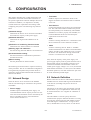
3.1 Outline
Fieldbus is a widely used bi-directional digital communication protocol for field devices that enable the
simultaneous output to many types of data to the
process control system.
The EJX multivariable transmitter Fieldbus
communication type employs the specification
standardized by The Fieldbus Foundation, and provides
interoperability between Yokogawa devices and those
produced by other manufacturers. Fieldbus comes with
software consisting of five AI function blocks that
enable the flexible implementation of systems.
For information on other features, engineering, design,
construction work, startup and maintenance of
Fieldbus, refer to “Fieldbus Technical Information” (TI
38K03A01-01E).
3.2 Internal Structure of EJX
Multivariable Transmitter
The EJX Multivariable transmitter contains two virtual
field devices (VFD) that share the following functions.
3.2.1 System/network Management VFD
• Sets node addresses and Physical Device tags (PD
Tag) necessary for communication.
• Controls the execution of function blocks.
• Manages operation parameters and communication
resources (Virtual Communication Relationship:
VCR).
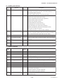
(4)LCD Transducer block
• Controls the display of the integral indicator.
(5)AI function block
• Condition raw data from the Transducer block.
• Output differential pressure, static pressure and
capsule temperature signals.
• Carry out scaling, damping and square root extraction.
(6)SC function block
• Converts the input signal value based on the
segment table function.
(7)IT function block
• Integrates one or two input signals and outputs the
result.
(8)IS function block
• Selects one of multiple input signals according to
the specified selection method and outputs the
signal.
(9)AR function block
• Performs ten types of calculations on a combination
of two main input signals and three auxiliary input
signals.
(10)PID function block
• Performs the PID control computation based on the
deviation of the measured value from the setpoint.
3.2.2 Function Block VFD
(1)Resource block
• Manages the status of EJX hardware.
• Automatically informs the host of any detected
faults or other problems.
(2)SENSOR Transducer block
• Converts sensor output to pressure, static pressure,
and capsule temperature signals, and transfers to the
AI function blocks and flow transducer blok.
(3)FLOW Transducer block
• Accepts differential pressure, static pressure and
external temperature data from the transducer block,
calculates flow, and transfer to the AI function
block.
3-1
IM 01C25R03-01E
3. ABOUT FIELDBUS
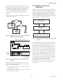
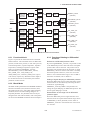
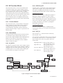
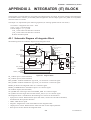
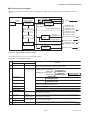
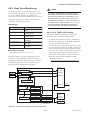
3.3 Logical Structure of Each
Block
EJX Multivariable Transmitter
Fieldbus
System/network management VFD
PD Tag
Communication
parameters
Node address
VCR
Function block
execution schedule
Link Master
Function block VFD
LCD
LCD
Transducer block
Block tag
Parameters
PID function
block (option)
AR function
block
IS function
block
IT function
block
Flow
Transducer block
Block tag
Sensor
Parameters
Sensor
input
SENSOR
Transducer block
SC function
block
AI function
block
AI function
block
AI function
block
AI function
block
AI function
block
Block tag
Block tag
Parameters
Parameters
Output
OUT
OUT_D
Resource block
Block tag
Parameters
F0301.EPS
Figure 3.1 Logical Structure of Each Block
Setting of various parameters, node addresses, and PD
Tags shown in Figure 3.1 is required before starting
operation.
3.4 Wiring System Configuration
The number of devices that can be connected to a
single bus and the cable length vary depending on
system design. When constructing systems, both the
basic and overall design must be carefully considered
to achieve optimal performance.
3-2
IM 01C25R03-01E
4. GETTING STARTED
4.
GETTING STARTED
Fieldbus is fully dependent upon digital communication protocol and differs in operation from conventional 4 to 20 mA transmission and the HART communication protocol. It is recommended that novice users
use field devices in accordance with the procedures
described in this section. The procedures assume that
field devices will be set up on a bench or in an
instrument shop.
Refer to Yokogawa when making arrangements to
purchase the recommended equipment.
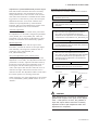
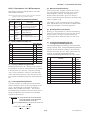
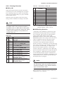
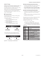
Connect the devices as shown in Figure 4.1. Connect
the terminators at both ends of the trunk, with a
minimum length of the spur laid for connection.
The polarity of signal and power must be maintained.
Fieldbus power
supply
4.1 Connection of Devices
The following are required for use with Fieldbus
devices:
• Power supply:
Fieldbus requires a dedicated power supply. It is
recommended that current capacity be well over the
total value of the maximum current consumed by all
devices (including the host). Conventional DC
current cannot be used as is.
• Host:
Used for accessing field devices. A dedicated host
(such as DCS) is used for an instrumentation line
while dedicated communication tools are used for
experimental purposes. For operation of the host,
refer to the instruction manual for each host. No
other details on the host are given in this manual.
HOST
Terminator
Terminator
F0401.EPS
Figure 4.1 Cabling
NOTE
• Terminator:
Fieldbus requires two terminators. Refer to the
supplier for details of terminators that are attached
to the host.
• Field devices:
Connect Fieldbus communication type EJX
multivariable transmitter. Two or more EJX devices
or other devices can be connected.
EJX
No CHECK terminal is used for Fieldbus EJX
multivariable transmitter. Do not connect the field
indicator and check meter.
Before using a Fieldbus configuration tool other than
the existing host, confirm it does not affect the loop
functionality in which all devices are already installed
in operation. Disconnect the relevant control loop from
the bus if necessary.
IMPORTANT
Connecting a Fieldbus configuration tool to a
loop with its existing host may cause communication data scrambling resulting in a functional
disorder or a system failure.
• Cable:
Used for connecting devices. Refer to “Fieldbus
Technical Information” (TI 38K03A01-01E) for
details of instrumentation cabling. For laboratory or
other experimental use, a twisted pair cable two to
three meters in length with a cross section of
0.9 mm2 or more and a cycle period of within 5 cm
(2 inches) may be used. Termination processing
depends on the type of device being deployed. For
EJX multivariable transmitter, use an M4 screw
terminal claw. Some hosts require a connector.
4-1
IM 01C25R03-01E
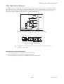
4. GETTING STARTED
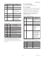
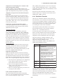
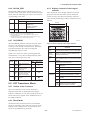
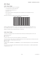
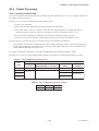
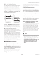
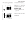
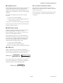
4.2 Host Setting
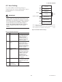
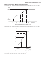
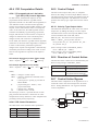
0x00
To activate Fieldbus, the following settings are
required for the host. Set the available address range to
cover the address set for EJX multivariable
transmitter’s.
0x0F
0x10
Not used
0x13
0x14
Bridge device
LM device
V(FUN)
Unused
V(NUN)
IMPORTANT
V(FUN)V(NUN)
Do not turn off the power immediately after
setting. When the parameters are saved to the
EEPROM, the redundant processing is executed
for an improvement of reliability. If the power is
turned off within 60 seconds after setting is
made, the modified parameters are not saved
and the settings may return to the original
values.
BASIC device
0xF7
0xF8
Default address
0xFB
0xFC
Portable device address
0xFF
Note 1: Bridge device: A linking device which brings data from one
or more H1 networks.
Note 2: LM device: with bus control function (Link Master function)
Note 3: BASIC device: without bus control function
F0402.EPS
Figure 4.2 Available Address Range
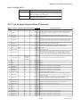
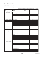
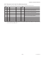
Table 4.1 Operation Parameters
Symbol
Parameter
Description and Settings
V (ST)
Slot-Time
Indicates the time necessary
for immediate reply of the
device. Unit of time is in
octets (256 µs). Set
maximum specification for
all devices. For EJX, set a
value of 4 or greater.
V (MID)
Minimum-Inter-PDUDelay
Minimum value of
communication data
intervals. Unit of time is in
octets (256 µs). Set the
maximum specification for
all devices. For EJX, set a
value of 4 or greater.
V (MRD) Maximum-ReplyDelay
The worst case time
elapsed until a reply is
recorded. The unit is Slottime; set the value so that
V (MRD) V (ST) is the
maximum value of the
specification for all
devices. For EJX, the
setting must be a value of
12 or greater.
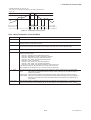
V (FUN) First-Unpolled-Node
Indicate the address next
to the address range used
by the host. Set 015 or
greater.
V (NUN) Number-ofconsecutiveUnpolled-Node
Unused address range.
T0401.EPS
4-2
IM 01C25R03-01E
4. GETTING STARTED
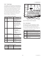
4.3 Bus Power ON
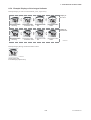
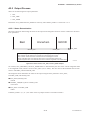
4.4 Integration of DD
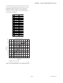
Turn on the power of the host and the bus. Where the
EJX multivariable transmitter is equipped with an LCD
indicator, first all segments are lit, then the display
begins to operate. If the indicator is not lit, check the
polarity of the power supply.
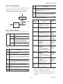
If the host supports DD (Device Description), the DD
of the EJX multivariable transmitter needs to be
installed. Check if host has the following directory
under its default DD directory.
Using the host device display function, check that the
EJX multivariable transmitter is in operation on the
bus.
The device information, including PD tag, Node
address, and Device ID, is described on the sheet
attached to the device. The device information is given
in duplicate on this sheet.
http://www.yokogawa.com/fld
DEVICE INFORMATION
Device ID
PD Tag
Device Revision
Node Address
Serial No.
Physical Location
:
:
:
:
:
:
594543\000E
(594543 is the manufacturer number of Yokogawa
Electric Corporation, and 000E is the EJX multivariable transmitter device number, respectively.)
If this directory is not found, the DD of the EJX910A
has not been included. Create the above directory and
copy the DD file (0m0n.ffo, 0m0n.sym) (m, n is a
numeral) into the directory. ‘0m’ in the file name
shows the device revision, and ‘0n’ shows the DD
revision. If you do not have the DD or capabilities
files, you can download them from our web site:
594543000EXXXXXXXX
FT1001
1
0xf5
XXXXXXXXXXXXXXXXX
Once the DD is installed in the directory, the name and
attribute of all parameters of the EJX multivariable
transmitter are displayed.
Note:
Off-line configuration is possible by using capabilities
files.
Our Device Description Files and Capabilities Files available at
http://www.yokogawa.com/fld (English) or
http://www.yokogawa.co.jp/Sensor/fieldbus/fieldbus.htm (Japanese)
EJX has two capabilities levels, “1” and “2”.
Select “Capabilities level = 1” when the EJX don’t
have LC1(PID function) option.
DEVICE INFORMATION
Device ID
PD Tag
Device Revision
Node Address
Serial No.
Physical Location
:
:
:
:
:
:
Select “Capabilities level = 2” when the EJX has
LC1(PID function) option.
594543000EXXXXXXXX
FT1001
1
0xf5
XXXXXXXXXXXXXXXXX
The capabilities level defines the kind and the number
of function blocks that can be used.
The table below shows the relation.
Note:
Our Device Description Files and Capabilities Files available at
http://www.yokogawa.com/fld (English) or
http://www.yokogawa.co.jp/Sensor/fieldbus/fieldbus.htm (Japanese)
The relation between and function blocks that can be used
Capabilities
Level
AI
SC
IT
IS
AR
PID
1
5
1
1
1
1
0
2
5
1
1
1
1
F0403.EPS
Figure 4.3 Device Information Sheet Attached to EJX
If no EJX multivariable transmitter is detected, check
the available address range and the polarity of the
power supply. If the node address and PD tag are not
specified when ordering, default value is factory set. If
two or more devices are connected at a time with
default value, only one device will be detected from
the host as devices have the same initial address.
Separately connect each device and set a different
address for each.
1
T0402.EPS
4.5 Reading the Parameters
To read EJX multivariable transmitter parameters,
select the AI1 block of the transmitter from the host
screen and read the OUT parameter. The current
selected signal is displayed. Check that
MODE_BLOCK of the function block and resource
block is set to AUTO, and change the signal input and
read the parameter again. A new designated value
should be displayed.
4-3
IM 01C25R03-01E
4. GETTING STARTED
4.6 Continuous Record of Values
If the host has a function that continuously records the
indications, use this function to list the indications
(values). Depending on the host being used, it may be
necessary to set the schedule of Publish (the function
that transmits the indication on a periodic basis).
4.7 Generation of Alarm
Generation of an alarm can be attempted from EJX
multivariable transmitter. Block alarm, Output limit
alarm, and Update alarm are informed to the host.
When generating alarm, a Link Object and a VCR
Static Entry need to be set. For details of Link Object
and VCR Static Entry, refer to section 5.6.1 Link
object and section 5.5.1 VCR Setting.
4-4
IM 01C25R03-01E
5. CONFIGURATION
5.
CONFIGURATION
This chapter describes how to adapt the function and
performance of the EJX multivariable transmitter to
suit specific applications. Because multiple devices are
connected to Fieldbus, it is important to carefully
consider the device requirements and settings when
configuring the system. The following steps must be
taken.
(1)Network design
Determines the devices to be connected to Fieldbus
and checks the capacity of the power supply.
(2)Network definition
Determines the tag and node addresses for all
devices.
(3)Definition of combining function blocks
Determines how function blocks are combined.
(4)Setting tags and addresses
Sets the PD Tag and node addresses for each device.
(5)Communication setting
Sets the link between communication parameters
and function blocks.
(6)Block setting
Sets the parameters for function blocks.
The following section describes in sequence each step
of this procedure. The use of a dedicated configuration
tool significantly simplifies this procedure. Refer to
Appendix 6 when the EJX multivariable transmitter is
used as Link Master.
5.1 Network Design
Select the devices to be connected to the Fieldbus
network. The following are essential for the operation
of Fieldbus.
• Power supply
Fieldbus requires a dedicated power supply. It is
recommended that current capacity be well over the
total value of the maximum current consumed by all
devices (including the host). Conventional DC
current cannot be used as is.
• Terminator
Fieldbus requires two terminators. Refer to the
supplier for details of terminators that are attached
to the host.
• Field devices
Connect the field devices necessary for instrumentation. The EJX multivariable transmitter has passed
the interoperability test conducted by The Fieldbus
Foundation. In order to properly start Fieldbus, it is
recommended that the devices used satisfy the
requirements of the above test.
• Host
Used for accessing field devices. A minimum of one
device with the bus control function is needed.
• Cable
Used for connecting devices. Refer to “Fieldbus
Technical Information” for details of instrumentation
cabling. Provide a cable sufficiently long to connect
all devices. For field branch cabling, use terminal
boards or a connection box as required.
First, check the capacity of the power supply. The
power supply capacity must be greater than the sum of
the maximum current consumed by all devices to be
connected to Fieldbus. The maximum current consumed (power supply voltage 9 V to 32 V) for the EJX
multivariable transmitter is 15 mA (24 mA in Software
download operation). The cable used for the spur must
be of the minimum possible length.
5.2 Network Definition
Before connection of devices with Fieldbus, define the
Fieldbus network. Allocate PD Tag and node addresses
to all devices (excluding such passive devices as
terminators).
The PD Tag is the same as the conventional one used
for the device. Up to 32 alphanumeric characters may
be used for definition. Use a hyphen as a delimiter as
required.
The node address is used to specify devices for
communication purposes. Because this data is too long
for a PD Tag, the host uses the node address in place
of the PD Tag for communication. A range of 20 to
247 (or hexadecimal 14 to F7) can be set. The device
5-1
IM 01C25R03-01E
5. CONFIGURATION
Table 5.2 Operation Parameter Values of the EJX to be
Set to LM Devices
(LM device) with bus control function (Link Master
function) is allocated from a smaller address number
(20) side, and other devices (BASIC device) without
bus control function allocated from a larger address
number (247) side respectively. Place the EJX
multivariable transmitter in the range of the BASIC
device. When the EJX multivariable transmitter is used
as Link Master, place it in the range of the LM device.
Set the range of addresses to be used to the LM device.
Set the following parameters.
Symbol
V (ST)
Parameters
Slot-Time
V (MID) Minimum-Inter-PDUDelay
Table 5.1 Parameters for Setting Address Range
Symbol
Parameters
Description
V (FUN) First-Unpolled-Node
Indicates the address next
to the address range used
for the host or other LM
device.
V (NUN) Number-ofconsecutiveUnpolled-Node
Unused address range
Description and Settings
Indicates the time necessary
for immediate reply of the
device. Unit of time is in
octets (256 µs). Set
maximum specification for
all devices. For EJX, set a
value of 5 or greater.
Minimum value of
communication data
intervals. Unit of time is in
octets (256 µs). Set the
maximum specification for
all devices. For EJX, set a
value of 4 or greater.
V (MRD) Maximum-Reply-Delay The worst case time
elapsed until a reply is
recorded. The unit is Slottime; set the value so that
V (MRD) V (ST) is the
maximum value of the
specification for all
devices. For EJX, the
setting must be a value of
12 or greater.
T0502.EPS
T0501.EPS
5.3 Definition of Combining
Function Blocks
The devices within the address range written as
“Unused” in Figure 5.1 cannot be used on a Fieldbus.
For other address ranges, the range is periodically
checked to identify when a new device is mounted.
Care must be taken to keep the unused device range as
narrow as possible so as to lessen the load on the
Fieldbus.
The input/output parameters for function blocks are
combined. As required, they can be combined with the
input of the control block. The setting is written to the
EJX link object. See “Block setting” in Section 5.6 for
the details. It is also possible to read values from the
host at proper intervals instead of connecting the EJX
block output to other blocks.
0x00
Not used
0x0F
0x10
0x13
0x14
The combined blocks need to be executed synchronously with other blocks on the communications
schedule. In this case, change the EJX schedule
according to the following table. The values in the
table are factory-settings.
Bridge device
LM device
V(FUN)
Unused
V(NUN)
Table 5.3 Execution Schedule of the EJX Function Blocks
V(FUN)V(NUN)
BASIC device
Index
0xF7
0xF8
Default address
0xFB
0xFC
Portable device address
0xFF
F0501.EPS
Figure 5.1 Available Range of Node Addresses
To ensure stable operation of Fieldbus, determine the
operation parameters and set them to the LM devices.
While the parameters in Table 5.2 are to be set, the
worst-case value of all the devices to be connected to
the same Fieldbus must be used. Refer to the specification of each device for details. Table 5.2 lists EJX
specification values.
Parameters
Setting (Enclosed is
factory-setting)
Cycle (MACROCYCLE)
period of control or
measurement. Unit is 1/32
ms. (16000 = 0.5 s)
269
(SM)
MACROCYCLE_
DURATION
276
(SM)
FB_START_ENTRY.1 AI1 block startup time.
Elapsed time from the start
of MACROCYCLE specified
in 1/32 ms. (0 = 0 s)
277
(SM)
FB_START_ENTRY.2 AI2 block startup time.
Elapsed time from the start
of MACROCYCLE specified
in 1/32ms.(8000=250ms)
FB_START_ENTRY.3 AI3 block startup time.
Elapsed time from the start
of MACROCYCLE specified
in 1/32ms.(16000=500ms)
278
(SM)
279
(SM)
FB_START_ENTRY.4 AI4 block startup time.
Elapsed time from the start
of MACROCYCLE specified
in 1/32ms. (24000=750ms)
280 to FB_START_ENTRY.5 Not used.
289
to
(SM) FB_START_ENTRY.14
T0503.EPS
5-2
IM 01C25R03-01E
5. CONFIGURATION
A maximum of 30 ms is taken for execution of AI
block. For scheduling of communications for combination with the next function block, the execution is so
arranged as to start after a lapse of longer than 30 ms.
In no case should function blocks of the EJX be
executed at the same time (execution time is overlapped).
Figure 5.3 shows an example of schedule based on the
loop shown in Figure 5.2.
5.4 Setting of Tags and
Addresses
This section describes the steps in the procedure to set
PD Tags and node addresses in the EJX multivariable
transmitter. There are three states of Fieldbus devices
as shown in Figure 5.4, and if the state is other than
the lowest SM_OPERATIONAL state, no function
block is executed. EJX must be transferred to this state
when an EJX tag or address is changed.
LIC100
EJX
#1
UNINITIALIZED
(No tag nor address is set)
Tag clear
FIC100
LI100
INITIALIZED
(Only tag is set)
EJX
#2
Address clear
FI100
FC100
Figure 5.2 Example of Loop Connecting Function Block of
Two EJX with Other Instruments
IN
LIC100
BKCAL_IN
CAS_IN
BKCAL_OUT
FIC100
FC100
IN
FI100
OUT
F0504.EPS
Figure 5.4 Status Transition by Setting PD Tag and Node
Address
Macrocycle (Control Period)
LI100
OUT
Address setting
SM_OPERATIONAL
(Tag and address are retained, and
the function block can be executed.)
F0502.EPS
Communication
Schedule
Tag setting
BKCAL_IN BKCAL_OUT
Unscheduled
Communication
Scheduled
Communication
F0503.EPS
Figure 5.3 Function Block Schedule and Communication
Schedule
When the control period (macrocycle) is set to more
than 4 seconds, set the following intervals to be more
than 1% of the control period.
EJX multivariable transmitter has a PD Tag (FT2001)
and node address (245, or hexadecimal F5) that are set
upon shipment from the factory unless otherwise
specified. To change only the node address, clear the
address once and then set a new node address. To set
the PD Tag, first clear the node address and clear the
PD Tag, then set the PD Tag and node address again.
Devices whose node addresses have been cleared will
have the default address (randomly chosen from a
range of 248 to 251, or from hexadecimal F8 to FB).
At the same time, it is necessary to specify the device
ID in order to correctly specify the device. The device
ID of the EJX multivariable transmitter is
594543000Exxxxxxxx. (The xxxxxxxx at the end of
the above device ID is a total of 8 alphanumeric
characters.)
- Interval between “end of block execution” and “start
of sending CD from LAS”
- Interval between “end of block execution” and “start
of the next block execution”
5-3
IM 01C25R03-01E
5. CONFIGURATION
5.5 Communication Setting
Table 5.4 VCR Static Entry
Subindex
To set the communication function, it is necessary to
change the database residing in SM-VFD.
Parameter
Description
1
FasArTypeAndRole
Indicates the type and role of
communication (VCR). The
following 4 types are used
for EJX.
0x32: Server (Responds to
requests from host.)
0x44: Source (Transmits
alarm or trend.)
0x66: Publisher (Sends
block output to other
blocks.)
0x76: Subscriber (Receives
output of other blocks.)
Server(QUB) VCR
A Server responds to requests from a host. This
communication needs data exchange. This type of
communication is called QUB (Queued Usertriggered Bidirectional) VCR.
Source (QUU) VCR
A Source multicasts alarms or trends to other
devices. This type of communication is called QUU
(Queued User-triggered Unidirectional) VCR.
Publisher (BNU) VCR
A Publisher multicasts block output to another
function block(s). This type of communication is
called BNU (Buffered Network-triggered Unidirectional) VCR.
Subscriber (BNU) VCR
A Subscriber receives output of another function
block(s).
2
FasDllLocalAddr
Sets the local address to
specify VCR in EJX. A range
of 20 to F7 in hexadecimal.
3
FasDllConfigured
RemoteAddr
Sets the node address of the
called party for
communication and the
address (DLSAP or DLCEP)
used to specify VCR in that
address. For DLSAP or
DLCEP, a range of 20 to F7
in hexadecimal is used.
Addresses in Subindex 2
and 3 need to be set to the
same contents of the VCR
as the called party (local and
remote are reversed).
4
FasDllSDAP
Specifies the quality of
communication. Usually, one
of the following types is set.
0x2B: Server
0x01: Source (Alert)
0x03: Source (Trend)
0x91: Publisher/Subscriber
A Server VCR is capable to responding to requests
from a Client (QUB) VCR after the Client successfully
initiates connection to the Server. A Source VCR
transmits data without established connection. A Sink
(QUU) VCR on another device can receive it if the
Sink is configured so. A Publisher VCR transmits data
when LAS requests so. An explicit connection is
established from Subscriber (BNU) VCR(s) so that a
Subscriber knows the format of published data.
5
FasDllMaxConfirm
DelayOnConnect
To establish connection for
communication, a maximum
wait time for the called
party's response is set in
ms. Typical value is 60
secounds (60000).
6
FasDllMaxConfirm
DelayOnData
For request of data, a
maximum wait time for the
called party's response is
set in ms. Typical value is
60 secounds (60000).
7
FasDllMaxDlsduSize
Specifies maximum DL
Service Data unit Size
(DLSDU). Set 256 for Server
and Trend VCR, and 64 for
other VCRs.
8
FasDllResidual
ActivitySupported
Specifies whether
connection is monitored. Set
TRUE (0xff) for Server. This
parameter is not used for
other communication.
9
FasDllTimelinessClass Not used for EJX.
10
FasDllPublisherTime
WindowSize
Not used for EJX.
11
FasDllPublisher
SynchronizaingDlcep
Not used for EJX.
5.5.1 VCR Setting
Set VCR (Virtual Communication Relationship), which
specifies the called party for communication and
resources. EJX multivariable transmitter has 33 VCRs
whose application can be changed, except for the first
VCR, which is used for management.
EJX multivariable transmitter has VCRs of four types:
Each VCR has the parameters listed in Table 5.4.
Parameters must be changed together for each VCR
because modification of individual parameters may
cause inconsistent operation.
T0504-1.EPS
5-4
IM 01C25R03-01E
5. CONFIGURATION
Subindex
Parameter
5.6 Block Setting
Description
Set the parameter for function block VFD.
12
FasDllSubsriberTime
WindowSize
13
FasDllSubscriber
Not used for EJX.
SynchronizationDlcep
14
FmsVfdId
Sets VFD for EJX to be
used.
0x1: System/network
management VFD
0x1234: Function block
VFD
15
FmsMaxOutstanding
ServiceCalling
Set 0 to Server. It is not
used for other applications.
16
FmsMaxOutstanding
ServiceCalled
Set 1 to Server. It is not
used for other applications.
FmsFeatures
Supported
Indicates the type of
services in the application
layer. In the EJX, it is
automatically set according
to specific applications.
17
Not used for EJX.
5.6.1 Link Object
A link object combines the data voluntarily sent by the
function block with the VCR. The EJX multivariable
transmitter has 40 link objects. A single link object
specifies one combination. Each link object has the
parameters listed in Table 5.6. Parameters must be
changed together for each VCR because the
modifications made to each parameter may cause
inconsistent operation.
Table 5.6 Link Object Parameters
Subindex
Parameters
1
LocalIndex
Sets the index of function
block parameters to be
combined; set “0” for Trend
and Alert.
2
VcrNumber
Sets the index of VCR to
be combined. If set to “0”,
this link object is not used.
3
RemoteIndex
Not used in EJX. Set to “0”.
4
ServiceOperation
Set one of the following.
Set only one each for link
object for Alert or Trend.
0: Undefined
2: Publisher
3: Subscriber
6: Alert
7: Trend
5
StaleCountLimit
Set the maximum number
of consecutive stale input
values which may be
received before the input
status is set to BAD. To
avoid the unnecessary
mode transition caused
when the data is not
correctly received by
subscriber, set this
parameter to “2” or more.
T0504-2.EPS
33 VCRs are factory-set as shown in the table below.
Table 5.5 VCR List
Index
(SM)
VCR
Number
293
1
For system management (Fixed)
294
2
Server (LocalAddr = 0xF3)
295
3
Server (LocalAddr = 0xF4)
296
4
Server (LocalAddr = 0xF7)
297
5
Trend Source (LocalAddr = 0x07,
Remote Address=0x111)
298
6
Publisher for AI1 (LocalAddr = 0x20)
299
7
Alert Source (LocalAddr = 0x07,
Remote Address=0x110)
300
8
Server (LocalAddr = 0xF9)
301
9
302 to 315 10 to 33
Factory Setting
Publisher for AI2 (LocalAddr = 0x21)
Not used.
T0505.EPS
5.5.2 Function Block Execution Control
According to the instructions given in Section 5.3, set
the execution cycle of the function blocks and schedule
of execution.
Description
T0506.EPS
Set link objects as shown in Table 5.7.
Table 5.7 Factory-Settings of Link Objects (example)
Index
Link Object #
Factory Settings
30000
1
AI1.OUT → VCR#6
30001
2
Trend → VCR#5
30002
3
Alert → VCR#7
30003
4
AI2.OUT → VCR#9
30004 to
30039
5 to 40
Not used
T0507.EPS
5-5
IM 01C25R03-01E
5. CONFIGURATION
5.6.2 Trend Object
SMIB
(System
Resource Transducer
Management
AI1 OUT AI2 OUT
block
block
Information
Base)
It is possible to set the parameter so that the function
block automatically transmits Trend. EJX multivariable
transmitter has seven Trend objects, six of which are
used for Trend in analog mode parameters and one is
used for Trend in discrete mode parameter. A single
Trend object specifies the trend of one parameter.
NMIB
(Network
Management
Information
Base)
1
2
3
4
Block Index
Parameter Relative
Index
Sample Type
Sample Interval
EJX
#1
VCR
#2
#3
#4
#8
#3
#4
#6
#9
#7
#2
#5
Fieldbus Cable
Description
Host 1
Sets the leading index of
the function block that
takes a trend.
Sets the index of
parameters taking a trend
by a value relative to the
beginning of the function
block. In the EJX AI block,
the following three types of
trends are possible.
7: PV
8: OUT
19: FIELD_VAL
Specifies how trends are
taken. Choose one of the
following 2 types:
1: Sampled upon
execution of a function
block.
2: The average value is
sampled.
5
Last Update
The last sampling time.
List of Status
Status part of a sampled
parameter.
Host 2
Device 1
Device 2
F0505.EPS
Figure 5.5 Example of Default Configuration
5.6.3 View Object
This object forms a group of parameters in a block.
One advantage brought by forming groups of parameters is the reduction of load for data transactions.
View Object has the parameters listed in Table 5.11 to
5.15. Purpose of View Objects is shown in Table 5.10.
Table 5.10 Purpose of Each View Object
Description
Specifies sampling
intervals in units of 1/32
ms. Set the integer
multiple of the function
block execution cycle.
6 to 21
21 to 37 List of Samples
#1
DLSAP 0xF8 0xF3 0xF4 0xF7 0xF9 0x20 0x21 0x07
DLCEP
Table 5.8 Parameters for Trend Objects
Parameters
Trend
Link
object
Each Trend object has the parameters listed in Table
5.8. The first four parameters are the items to be set.
Before writing to a Trend object, it is necessary to
release the WRITE_LOCK parameter.
Subindex
Alert
FBOD
VIEW_1
Set of dynamic parameters required by operator
for plant operation. (PV, SV, OUT, Mode etc.)
VIEW_2
Set of static parameters which need to be
shown to plant operator at once. (Range etc.)
VIEW_3
Set of all the dynamic parameters.
VIEW_4
Set of static parameters for configuration or
maintenance.
T0510.EPS
Data part of a sampled
parameter.
T0508.EPS
Seven trend objects are factory-set as shown Table 5.9.
Table 5.9 Trend Object are Factory-Set
Index
Parameters
Factory Settings
32000 to
32005
TREND_FLT.1 to
TREND_FLT.5
Not used.
32006
TREND_DIS.1
Not used.
T0509.EPS
5-6
IM 01C25R03-01E
5. CONFIGURATION
Table 5.11 View Object for Resource Block
Relative
Parameter Mnemonic VIEW VIEW VIEW VIEW
Index
1
2
3
4
4
46
DEVICE_STATUS_2
Relative
Parameter Mnemonic VIEW VIEW VIEW VIEW
Index
1
2
3
4
1
ST_REV
2
2
2
2
2
TAG_DESC
3
STRATEGY
4
ALERT_KEY
47
DEVICE_STATUS_3
4
2
48
DEVICE_STATUS_4
4
1
49
DEVICE_STATUS_5
4
DEVICE_STATUS_6
4
5
MODE_BLK
4
4
50
6
BLOCK_ERR
2
2
51
DEVICE_STATUS_7
4
1
52
DEVICE_STATUS_8
4
7
RS_STATE
8
TEST_RW
53
SOFTDWN_PROTECT
1
9
DD_RESOURCE
54
SOFTDWN_FORMAT
1
10
MANUFAC_ID
4
55
SOFTDWN_COUNT
SOFTDWN_ACT_AREA
1
1
2
11
DEV_TYPE
2
56
12
DEV_REV
1
57
SOFTDWN_MOD_REV
16
1
58
SOFTDWN_ERROR
2
13
DD_REV
14
GRANT_DENY
15
HARD_TYPES
2
RESTART
17
FEATURES
18
FEATURE_SEL
19
CYCLE_TYPE
20
CYCLE_SEL
21
MIN_CYCLE_T
22
MEMORY_SIZE
23
NV_CYCLE_T
24
FREE_SPACE
25
FREE_TIME
26
SHED_RCAS
4
27
SHED_ROUT
4
28
FAULT_STATE
29
SET_FSTATE
30
CLR_FSTATE
31
MAX_NOTIFY
32
LIM_NOTIFY
1
33
CONFIRM_TIME
4
34
WRITE_LOCK
1
35
UPDATE_EVT
36
BLOCK_ALM
2
4
2
4
4
4
4
1
1
1
8
8
ALARM_SUM
2
39
WRITE_PRI
1
42
SOFT_REV
43
SOFT_DESC
44
SIM_ENABLE_MSG
45
DEVICE_STATUS_1
35
2
ACK_OPTION
WRITE_ALM
73
2
37
ITK_VER
30
2
38
41
22
T0511-2.EPS
16
40
Totals (# bytes)
2
2
4
T0511-1.EPS
5-7
IM 01C25R03-01E
5. CONFIGURATION
Table 5.12 View Object for SENSOR Transducer Block
Relative
Index
1
2
3
4
5
6
7
8
9
10
11
12
13
14
15
16
17
18
19
20
21
22
23
24
25
26
27
28
29
30
31
32
33
34
35
36
37
38
39
40
41
42
43
44
45
46
47
48
49
50
51
52
53
54
55
56
57
58
Parameter Mnemonic
ST_REV
TAG_DESC
STRATEGY
ALERT_KEY
MODE_BLK
BLOCK_ERR
UPDATE_EVT
BLOCK_ALM
TRANSDUCER_DIRECTORY
TRANSDUCER_TYPE
XD_ERROR
COLLECTION_DIRECTORY
PRIMARY_VALUE_TYPE
PRIMARY_VALUE
PRIMARY_VALUE_RANGE
CAL_POINT_HI
CAL_POINT_LO
CAL_MIN_SPAN
CAL_UNIT
SENSOR_TYPE
SENSOR_RANGE
SENSOR_SN
SENSOR_CAL_METHOD
SENSOR_CAL_LOC
SENSOR_CAL_DATE
SENSOR_CAL_WHO
SENSOR_ISOLATOR_MTL
SENSOR_FILL_FLUID
SECONDARY_VALUE
SECONDARY_VALUE_UNIT
CAL_DEVIATION_HI
CAL_DEVIATION_LO
EXTERNAL_ZERO_TRIM
PRIMARY_VALUE_FTIME
TERTIARY_VALUE
SP_VALUE_TYPE
SP_VALUE_RANGE
CAL_SP_POINT_HI
CAL_SP_POINT_LO
CAL_SP_MIN_SPAN
CAL_SP_UNIT
CAL_SP_DEVIATION_HI
CAL_SP_DEVIATION_LO
SP_VALUE_FTIME
ATM_PRESS
CURRENT_ATM_PRESS_ENABLE
EXT_TEMP_VAL
EXT_TEMP_RANGE
CAL_EXT_TEMP_POINT_HI
CAL_EXT_TEMP_POINT_LO
CAL_EXT_TEMP_MIN_SPAN
CAL_EXT_TEMP_UNIT
CAL_EXT_TEMP_DEVIATION_HI
CAL_EXT_TEMP_DEVIATION_LO
EXT_TEMP_VALUE_FTIME
EXT_TEMP_OPTS
FIXED_EXT_TEMP_VALUE
SIMULATE_MODE
VIEW
1
VIEW
2
VIEW
3_1
VIEW
3_2
VIEW
3_3
VIEW
3_4
VIEW
4_1
VIEW
4_2
VIEW
4_3
VIEW
4_4
VIEW
4_5
2
2
2
2
2
2
2
2
2
2
2
2
1
4
2
2
1
4
2
2
2
1
2
2
5
5
11
4
4
4
2
2
11
32
1
32
7
32
2
2
5
5
2
4
4
1
4
5
5
2
11
4
4
4
2
4
4
4
4
1
5
5
11
4
4
4
2
4
4
4
2
4
1
T0512-1.EPS
5-8
IM 01C25R03-01E
5. CONFIGURATION
Relative
Index
59
60
61
62
63
64
65
66
67
68
69
70
71
72
73
74
75
76
77
78
79
80
81
82
83
84
85
86
87
88
89
90
91
92
93
94
95
96
97
98
99
100
101
102
103
104
105
106
107
108
109
110
111
112
113
Parameter Mnemonic
SIMULATE_DPRESS
SIMULATE_SPRESS
SIMULATE_ETEMP
EXT_TEMP_SENSOR_SN
CLEAR_CAL
CAP_TEMP_VAL
CAP_TEMP_RANGE
AMP_TEMP_VAL
AMP_TEMP_RANGE
MODEL
SPECIAL_ORDER_ID
MANUFAC_DATE
CAP_GASKET_MTL
FLANGE_MTL
D_VENT_PLUG
FLANGE_TYPE
REM_SEAL_ISOL_MTL
FLANGE_SIZE
REM_SEAL_NUM
REM_SEAL_FILL_FLUID
REM_SEAL_TYPE
ALARM_SUM
AUTO_RECOVERY
MS_CODE
DIAG_MODE
DIAG_PERIOD
DIAG_PRI
DIAG_ERR
DIAG_H_ALM
DIAG_L_ALM
DIAG_OPTION
REF_LIM_ FDPMIN
REF_LIM_ FSPMIN
REF_LIM_ BLKFMAX
COMP_FLAG
DIAG_LIM
DIAG_COUNT
REFERENCE_TIME
REFERENCE_FDP
REFERENCE_FSPL
REFERENCE_FSPH
REFERENCE_BLKF
REFERENCE_DPAVG
VALUE_TIME
VALUE_ FDP
VALUE_ FSPL
VALUE_ FSPH
VALUE_ BLKF
VALUE_DPAVG
RATIO_FDP
RATIO_FSPL
RATIO_FSPH
CRATIO_FDP
NRATIO_FDP
DIAG_APPLICABLE
VIEW
1
VIEW
2
VIEW
3_1
VIEW
3_2
VIEW
3_3
VIEW
3_4
VIEW
4_1
VIEW
4_2
VIEW
4_3
VIEW
4_4
VIEW
4_5
5
5
5
5
5
5
5
11
11
16
32
7
1
1
1
1
1
1
1
1
1
8
8
1
1
2
1
2
13
13
2
4
4
4
1
40
1
8
5
5
5
5
5
8
5
5
5
5
5
5
5
5
5
5
2
T0512-2.EPS
5-9
IM 01C25R03-01E
5. CONFIGURATION
Relative
Index
114
115
116
117
118
119
120
121
122
123
124
125
126
127
128
129
130
131
132
133
134
135
136
137
138
139
Parameter Mnemonic
VIEW
1
VIEW
2
VIEW
3_2
VIEW
3_3
VIEW
3_4
VIEW
4_1
VIEW
4_2
VIEW
4_3
VIEW
4_4
VIEW
4_5
5
FLG_TEMP_VAL
FLG_TEMP_RANGE
FLG_TEMP_COEF
FLG_TEMP_PRI
FLG_TEMP_H_LIM
FLG_TEMP_L_LIM
FLG_TEMP_ALM
TEST_KEY1
TEST_KEY2
TEST_KEY3
TEST1
TEST2
TEST3
TEST4
TEST5
TEST6
TEST7
TEST8
TEST9
TEST10
TEST11
TEST12
TEST13
TEST14
TEST15
TEST16
Totals (# bytes)
VIEW
3_1
11
4
1
4
4
13
4
16
32
2
2
1
1
1
2
2
15
38
30
33
49
82
101
32
108
103
99
106
77
95
26
T0512-3.EPS
5-10
IM 01C25R03-01E
5. CONFIGURATION
Table 5.13 View Object for LCD Transducer Block
Relative
Index
Parameter Mnemonic
VIEW VIEW VIEW VIEW VIEW VIEW VIEW
1
2
3_1 4_1 4_2 4_3 4_4
1
ST_REV
2
TAG_DESC
3
STRATEGY
4
ALERT_KEY
5
MODE_BLK
4
6
BLOCK_ERR
2
7
8
9
2
2
2
2
2
2
Relative
Index
2
Parameter Mnemonic
VIEW VIEW VIEW VIEW VIEW VIEW VIEW
1
2
3_1 4_1 4_2 4_3 4_4
42
BLOCK_TAG5
32
43
PARAMETER_SEL5
2
2
44
DISPLAY_TAG5
8
1
45
UNIT_SEL5
1
4
46
DISPLAY_UNIT5
8
2
47
EXP_MODE5
1
UPDATE_EVT
48
BLOCK_TAG6
32
BLOCK_ALM
49
PARAMETER_SEL6
2
TRANSDUCER_
50
DISPLAY_TAG6
8
DIRECTORY
51
UNIT_SEL6
1
52
DISPLAY_UNIT6
8
53
EXP_MODE6
1
10
TRANSDUCER_TYPE
2
11
XD_ERROR
1
2
2
2
12
COLLECTION_
54
BLOCK_TAG7
32
DIRECTORY
55
PARAMETER_SEL7
2
1
13
DISPLAY_SEL
2
56
DISPLAY_TAG7
8
14
INFO_SEL
1
57
UNIT_SEL7
1
15
BLOCK_TAG1
32
58
DISPLAY_UNIT7
8
16
PARAMETER_SEL1
2
59
EXP_MODE7
1
17
DISPLAY_TAG1
8
60
BLOCK_TAG8
32
18
UNIT_SEL1
1
61
PARAMETER_SEL8
2
19
DISPLAY_UNIT1
8
62
DISPLAY_TAG8
8
20
EXP_MODE1
1
63
UNIT_SEL8
1
21
BLOCK_TAG2
32
64
DISPLAY_UNIT8
8
22
PARAMETER_SEL2
2
65
EXP_MODE8
1
23
DISPLAY_TAG2
8
66
BLOCK_TAG9
32
24
UNIT_SEL2
1
67
PARAMETER_SEL9
2
25
DISPLAY_UNIT2
8
68
DISPLAY_TAG9
8
26
EXP_MODE2
1
69
UNIT_SEL9
1
27
BLOCK_TAG3
32
70
DISPLAY_UNIT9
8
28
PARAMETER_SEL3
2
71
EXP_MODE9
1
29
DISPLAY_TAG3
8
72
BLOCK_TAG10
32
30
UNIT_SEL3
1
73
PARAMETER_SEL10
2
31
DISPLAY_UNIT3
8
74
DISPLAY_TAG10
8
32
EXP_MODE3
1
75
UNIT_SEL10
1
33
BLOCK_TAG4
32
76
DISPLAY_UNIT10
8
34
PARAMETER_SEL4
2
77
EXP_MODE10
1
35
DISPLAY_TAG4
8
36
UNIT_SEL4
1
37
DISPLAY_UNIT4
8
38
EXP_MODE4
1
39
BAR_GRAPH_SELECT
40
DISPLAY_CYCLE
1
41
TEST40
1
Totals (# bytes)
11 112 11 113 106 106 106
T0513.EPS
5-11
IM 01C25R03-01E
5. CONFIGURATION
Table 5.14 View Object for Flow Transducer Block
Relative
Index
1
2
3
4
5
6
7
8
9
10
11
13
14
15
16
17
18
19
20
21
22
23
24
25
26
27
28
29
30
31
32
33
34
35
36
37
38
39
40
41
42
43
44
45
46
47
48
49
50
51
52
53
Parameter Mnemonic
ST_REV
TAG_DESC
STRATEGY
ALERT_KEY
MODE_BLK
BLOCK_ERR
UPDATE_EVT
BLOCK_ALM
TRANSDUCER_DIRECTORY
TRANSDUCER_TYPE
XD_ERROR
FLOW_VALUE_TYPE
FLOW_VALUE
FLOW_VALUE_UNIT
FLOW_VALUE_DECIMAL
FLOW_VALUE_FTIME
DIFF_PRESSURE
DIFF_PRESSURE_UNIT
STATIC_PRESSURE
STATIC_PRESSURE_UNIT
EXT_TEMPERATURE
EXT_TEMPERAURE_UNIT
FLOW_CALCULATION_MODE
FIXED_FLOW_VALUE
REF_STATIC_PRESSURE
REF_EXT_TEMPERATURE
TEMP_K1_FOR_LIQUID
FLUID_TYPE_CODE
ALARM_SUM
DENSITY_UNIT_CODE
LENGTH_UNIT_CODE
PRIMARY_DEVICE_CODE
PRIMARY_DEVICE_DIAMETER
PRIMARY_DEVICE_
EXPANSION_COEF
2
2
Relative
VIEW VIEW VIEW VIEW
3
Index Parameter Mnemonic
1
2
4
2
2
2
1
ST_REV
2
2
2
2
2
1
4
2
2
1
4
2
2
2
1
2
1
5
5
2
1
4
5
5
2
5
5
2
5
5
2
1
4
4
4
4
1
8
8
2
2
1
4
4
PRIMARY_DEVICE_
REF_TEMPERATURE
4
PIPE_DIAMETER
PIPE_EXPANSION_COEF
PIPE_REF_TEMPERATURE
BASE_DENSITY_FOR_
VOLUME_FLOW
4
4
4
4
FLOW_CONFIG1
FLOW_CONFIG2
FLOW_CONFIG3
FLOW_CONFIG4
CORRECTION_VALUE
CONFIG_SOFT_REV
CONFIG_DATE
CONFIG_WHO
CONFIG_STATUS
CONFIG_VSTRING32
CONFIG_VSTRING16
CONFIG_OSTRING32
CONFIG_OSTRING2
20
12
Totals (# bytes)
Table 5.15 View Object for AI Function Block
VIEW VIEW VIEW VIEW VIEW
1
2
3
4_1 4_2
16
32
16
16
32
2
2
TAG_DESC
3
STRATEGY
2
4
ALERT_KEY
1
5
MODE_BLK
4
4
6
BLOCK_ERR
2
2
7
PV
5
5
8
OUT
5
5
9
SIMULATE
10
XD_SCALE
11
11
OUT_SCALE
11
12
GRANT_DENY
2
13
IO_OPTS
2
14
STATUS_OPTS
2
15
CHANNEL
2
16
L_TYPE
1
17
LOW_CUT
4
18
PV_FTIME
19
FIELD_VAL
20
UPDATE_EVT
21
BLOCK_ALM
22
ALARM_SUM
23
ACK_OPTION
2
24
ALARM_HYS
4
25
HI_HI_PRI
1
26
HI_HI_LIM
4
27
HI_PRI
1
28
HI_LIM
4
29
LO_PRI
1
30
LO_LIM
4
31
LO_LO_PRI
1
32
LO_LO_LIM
4
33
HI_HI_ALM
34
HI_ALM
35
LO_ALM
36
LO_LO_ALM
37
OUT_D_SEL
38
OUT_D
Totals (# bytes)
4
5
5
8
8
2
2
31
26
33
48
T0514.EPS
32
32
32
2
39
98
71
92
100
T0513-2.EPS
5-12
IM 01C25R03-01E
5. CONFIGURATION
Table 5.16 Indexes of View for Each Block
VIEW_1 VIEW_2 VIEW_3 VIEW_4
Resourse Block
40100
40101
SENSOR Transducer
Block
40200
40201
40230
40231
40232 40233 to
40234
LCD Transducer Block 40250
40251
40252
40253
AI1 Function Block
40400
40401
40402
40403
AI2 Function Block
40410
40411
40412
40413
AI3 Function Block
40420
40421
40422
40423
FLOW
Transducer block
40102
40103
40202 to 40204 to
40203
40206
AI4 Function block
40430
40431
40432
40433
AI5 Function block
40440
40441
40442
40443
PID Function Block
40800
40801
40802
40803
SC Function Block
41450
41451
41452
41453
IT Function Block
41600
41601
41602
41603
IS Function Block
41700
41701
41702
41703
AR Function Block
41750
41751
41752
41753
T0515.EPS
5.6.4 Function Block Parameters
Function block parameters can be read from the host or
can be set. For a list of the parameters of blocks held
by the EJX multivariable transmitter, refer to “9.
PARAMETERS LISTS”. For the function blocks other
than AI block, LM function, software download
function and advanced diagnostic, refer to Appendix 1
to 8.
5-13
IM 01C25R03-01E
6. EXPLANATION OF BASIC ITEMS
6.
EXPLANATION OF BASIC ITEMS
6.1 Outline
(2) Actual (Actual mode):
Indicates the current operating condition.
(3) Permit (Permitted mode):
Indicates the operating condition that the block
is allowed to take.
(4) Normal (Normal mode):
Indicates the operating condition that the block
will usually take.
This chapter describes the SENSOR transducer block,
the LCD transducer block, and the AI function block
and explains basic parameter settings. Refer to Appendixes for other function blocks, LM function, and
software download function.
6.2 Setting and Changing Parameters for the Whole Process
IMPORTANT
Do not turn off the power immediately after
setting. When the parameters are saved to the
EEPROM, the redundant processing is executed
for an improvement of reliability. If the power is
turned off within 60 seconds after setting is
made, the modified parameters are not saved
and the settings may return to the original
values.
6.3 SENSOR Transducer Block
The SENSOR transducer block is in between the
sensor and the AI function blocks. It calculates
differential pressure, static pressure, external temperature, and capsule temperature from sensor signals.
Then it performs damping and range checks for the
measured values of these three variables and sends
signals to the AI function block and Flow transducer
block. Figure 6.1 presents the signal flow between
blocks.
Block mode
Many parameters require a change of the block mode
of the function block to O/S (Out of Service) when
their data is changed. To change the block mode of the
function block, its MODE_BLK needs to be changed.
The MODE_BLK is comprised of the four subparameters below:
(1) Target (Target mode):
Sets the operating condition of the block.
Sensor Transducer Block
Flow Transducer Block
FLOW_VAL
(Channel5)
PRIMARY_VALUE [DP]
(Channel1)
SECONDARY_VALUE [SP-H]
(Channel2)
AI Function Block
CHANNEL=?
TERITARY_VALUE [SP-L]
(Channel3)
AI
EXT_TEMP_VAL
(Channel4)
AI
CAP_TEMP_VAL
(Channel6)
AI
AMP_TEMP_VAL
(Channel7)
AI
FLG_TEMP_VAL
(Channel8)
F0601a.EPS
Figure 6.1 Signal Flow Diagram
6-1
IM 01C25R03-01E
6. EXPLANATION OF BASIC ITEMS
Simulation
value
Pressure
/differential
pressure
calculation
Sensor
signals
Static
pressure
calculation
Range
check
Adjustment
Damping
processing
Unit
check
Simulation
value
Range
check
Adjustment
Damping
processing
Unit
check
Simulation
value
RTD
signals
External
temperature
calculation
Range
check
Capsule
temperature
calculation
Range
check
Unit
check
Amplifier
temperature
calculation
Range
check
Unit
check
Flange
temperature
calculation
Range
check
Unit
check
Historical
records
Adjustment
Damping
processing
Unit
check
PRIMARY_VALUE
(Channel1)
H-side
static
pressure
SECONDARY_VALUE
(Channel2)
L-side
static
pressure
TERTIARY_VALUE
(Channel3)
EXT_TEMP_VAL
(Channel4)
CAP_TEMP_VAL
(Channel6)
AMP_TEMP_VAL
(Channel7)
FLG_TEMP_VAL
(Channel8)
Equipment
information
F0601.EPS
Figure 6.2 SENSOR Transducer Functional Block
6.3.1 Functional block
Figure 6.2 presents the functional block of the SENSOR transducer. The calculated values of differential
pressure, H-side static pressure, L-side static pressure,
external temperature, capsule temperature, amplifier
temperature, and flange temperature (option code:
/DG1) are assigned to PRIMARY_VALUE,
SECONDARY_VALUE, TERTIARY_VALUE,
EXT_TEMP_VAL, CAP_TEMP_VAL,
AMP_TEMP_VAL, and FLG_TEMP_VAL (option
code: /DG1) respectively. Measured values output to
the AI function blocks are selected by the Channel
parameter of those blocks.
6.3.2 Block Mode
The Block modes permitted for the SENSOR transducer
block are Automatic (Auto) and Out of Service (O/S).
The mode must be set to Auto under normal operating
conditions, and to O/S when making changes to an
important parameter. For parameters that can only be
changed in the Auto and O/S modes, refer to the parameter list for the SENSOR Transducer block in Chapter 9.
6.3.3 Functions Relating to Differential
Pressure
Reference to differential pressure value:
By accessing PRIMARY_VALUE, it is possible to refer
to the differential pressure value and status. The update
period of this value is 200 msec. The pressure unit is
selected by XD_SCALE.unit of the AI block, in which
PRIMARY_VALUE is selected. The status is normally
Good-Non Specific. However, in the case of a sensor
failure or out of measurement range, it turns to Bad or
Uncertain. For details, refer to Table 8.9.
Setting of signal damping for differential pressure:
When the differential pressure signal fluctuates greatly,
the fluctuation can be reduced by increasing the time
constant for signal damping.
PRIMARY_VALUE_FTIME is the parameter for
setting the signal damping for differential pressure. The
unit of signal damping is second.
Determination of the range limit of differential
pressure signal:
When the differential pressure signal deviates more
than 10% from the capsule measurement range shown
in PRIMARY_VALUE_RANGE, set the status of
PRIMARY_VALUE to Uncertain-Sensor Conversion
not Accurate.
6-2
IM 01C25R03-01E
6. EXPLANATION OF BASIC ITEMS
Adjustment of pressure/differential pressure signal:
EJX multivariable transmitter have been accurately
adjusted according to the specifications at factory
setting. Minimal errors can occur due to the environment where the transmitter is installed and the mounting position. To fine-tune any errors, three zero/span
adjustment functions can be used: automatic and
manual zero/span adjustment by communication
terminals, and zero-point adjustment by means of the
external adjustment screw on the transmitter.
Procedure for automatic adjustment
The procedure for automatic adjustment is as follows:
(1) Change the Block mode
Set MODE_BLK to O/S.
(2) Enter zero% pressure
Apply the actual zero% pressure to EJX multivariable
transmitter.
Automatic adjustment
The value of the pressure exerted on the point where
the adjustment is to be made is assigned to parameters
(CAL_POINT_LO, CAL_POINT_HI). After this
assignment is set, the amount of adjustment is calculated by the transmitter and automatically updated.
(3) Perform zero adjustment
When the value of the applied pressure is written to
CAL_POINT_LO, EJX calculates the amount of
adjustment for zero adjustment. The calculated amount
of adjustment is incorporated into CAL_DEVIATION_LO.
Manual adjustment
From the exerted pressure and the output of the
transmitter, calculate the amount of zero/span adjustment manually, and assign the calculated value to
parameters (CAL_DEVIATION_LO,
CAL_DEVIATION_HI).
(4) Input pressure for span adjustment
For span adjustment, apply the actual 100% pressure to
EJX multivariable transmitter.
(5) Performance of span adjustment
When the value of the applied pressure is written to
CAL_POINT_HI, EJX multivariable transmitter calculates
the amount of adjustment for span adjustment. The
calculated amount of adjustment is incorporated into
CAL_DEVIATION_HI.
Zero-point adjustment by the external screw.
With pressure being exerted on the point where the
adjustment is to be made, zero adjustment needs to be
performed. To do this, adjust the calculated value by
turning the external Zero-point adjustment screw, so
that it agrees with the actual input pressure (true
value). The output value increases when the screw is
rotated to the right. It decreases when the screw is
rotated to the left. The adjustment width is small when
the rotation speed is low and large when fast.
(6) Change the operation mode
Set MODE_BLK to AUTO for normal operation.
F0602.EPS
Calculated Value
Calculated Value
Span adjustment point
After zero adjustment
When performing zero-point adjustment by the external
screw, EXTERNAL_ZERO_TRIM needs to be set to
“Enable.”
0
0
Input pressure
Before zero
adjustment
After zero adjustment
Input pressure
After zero/span
adjustment
F0603.EPS
CAUTION
Span adjustment is a function for adjusting the
gradient with respect to the point of zero adjustment. If that point is not zero, the gradient of
input and output values cannot be accurately
adjusted. Perform span adjustment after zero
adjustment is completed.
6-3
IM 01C25R03-01E
6. EXPLANATION OF BASIC ITEMS
Diagnosis of adjustment results:
When the amount of zero adjustment or span adjustment exceeds any of the following adjustment limits,
“AL50: Adjustment range error for differential pressure” is displayed.
The conditions for zero/span adjustment are as follows:
<1> The point of zero adjustment is within ±10%
of the capsule range.
<2> The amount of zero adjustment is within ±10%
of the capsule range.
<3> The point of span adjustment is within the
capsule range.
<4> The input and output gradients after span
adjustment are within ±10% of the gradient at
factory setting.
6.3.4 Functions Relating to Static Pressure
Reference to static pressure value:
In SECONDARY_VALUE and TERTIARY_VALUE,
it is possible to refer to the H-side static pressure value
and the L-side static pressure value, respectively. The
update period of these values is 200 msec. The
pressure unit is selected by XD_SCALE.unit in the AI
block, in which SECONDARY_VALUE and
TERTIARY_VALUE are selected. The status is
normally Good-Non Specific. However, in the case of
a sensor failure or out of measurement range, it turns
to Bad or Uncertain. For specifics, refer to Table 8.9.
Setting of signal damping for static pressure:
SP_VALUE_FTIME is parameter that set signal
damping for static pressure signals. The unit of the
signal damping is second.
Determination of the range limit of static pressure
signal:
When the static pressure signal exceeds the maximum
working pressure (MWP) of the capsule, set the status
of PRIMARY_VALUE to Uncertain-Subnormal. Also,
set the status of SECONDARY_VALUE and
TERTIARY_VALUE to Uncertain-Sensor Conversion
not Accurate. The status under normal conditions is
Good-Non Specific.
Adjustment of static pressure signal:
The zero/span adjustment function can be used for
static signals, as in the case of differential pressure
signals. However, the zero-point adjustment by the
external screw function is not supported for static
pressure signal.
After this assignment is set, the amount of adjustment
is calculated by the transmitter and automatically
updated. The procedure for adjusting the static pressure
signal is the same as that of differential pressure signal.
Manual adjustment
From the exerted pressure and the output of the
transmitter, calculate the amount of zero/span adjustment manually and assign the calculated value to
parameters (CAL_SP_DEVIATION_LO,
CAL_SP_DEVIATION_HI).
Selection of static pressure signal type:
EJX910 multivariable transmitter measure the absolute
static pressure. Based on the assumption that atmospheric pressure is constant, these transmitters can
output signal equivalent to gauge pressure calculated
by deducting the atmospheric pressure (fixed value)
from the measured absolute pressure. The type of static
pressure signal output to SECONDARY_VALUE and
TERTIARY_VALUE is selected in
SP_VALUE_TYPE. SP_VALUE_TYPE allows
selection of gauge pressure or absolute pressure. When
selecting gauge pressure, set the value of the atmospheric pressure (fixed value) to ATM_PRESS. The
default value of ATM_PRESS is equal to the value of
standard atmospheric pressure (101.325 kPa).
Atmospheric pressure automatic setting:
When “Set” is set to the
CURRENT_ATM_PRESS_ENABLE parameter, the
present L-side static pressure can be automatically
assigned as the atmospheric pressure (ATM_PRESS).
To make this assignment, the SENSOR transducer
block must be set to the O/S mode. After the L-side
static pressure has been assigned to ATM_PRESS, the
value of CURRENT_ATM_PRESS_ENABLE automatically returns to “off”.
6.3.5 Functions Relating to External
Temperature
Reference to external temperature value:
The contact temperature and status of the RTD
connected at EXT_TEMP_VAL can be referenced. The
update period of this value is about 800 msec. The
external temperature unit is the unit selected at
XD_SCALE.Unit in the AI block where
EXT_TEMP_VAL is selected. Usually, the status
indicates Good-Non Specific; however, it changes to
Bad or Uncertain during a sensor malfunction or when
the measuring range is exceeded. For actual details, see
Table 8.9 Parameter Operations at Error Occurrence.
Automatic adjustment
The value of the static pressure exerted on the point
where adjustment is to be made is assigned to parameters (CAL_SP_POINT_LO, CAL_SP_POINT_HI).
6-4
IM 01C25R03-01E
6. EXPLANATION OF BASIC ITEMS
Assignment of the damping time constant of the
external temperature signal:
The EXT_TEMP_VALUE_FTIME parameter is for
setting the damping parameter of the external temperature
signal. The setting unit for this parameter is [seconds].
Judgment of range limit of the external temperature signal:
When the external temperature signal has deviated
from the measuring range (-200 to 850°C) by 85°C or
more, it is outside the external temperature specification range, and the status of the external temperature
signal (EXT_TEM_VAL) is set to Uncertain-Sensor
Conversion not Accurate.
Adjustment of external temperature signal:
A zero/span adjustment function is available for the
external temperature signal just like for the pressure
(differential pressure) signal.
Automatic adjustment
The temperature value is assigned to parameters
(CAL_EXT_TEMP_LO and CAL_EXT_TEMP_HI)
with the external temperature sensor immersed in the
temperature to be adjusted. After this assignment is
made, the adjustment amount is calculated internally by
the transmitter and the adjustment amount is automatically updated. The procedure for adjusting the external
temperature signal is the same as that of the differential
pressure signal.
Manual adjustment
From the assigned temperature and the output of the
transmitter, calculate the amount of zero/span adjustment manually and assign the calculated value to
parameters (CAL_EXT_TEMP_DEVIATION_LO and
CAL_EXT_TEMP_DEVIATION_HI).
EXT_TEMP_OPTS parameter, select one of Selection
0 (No): External temperature sensor, 1 (Yes): External
temperature fixed value mode, and 2 (Fall Back): Fixed
mode at broken wire.
When the external temperature fixed mode or fixed
mode at broken wire is selected, set the fixed value at
FIXED_EXT_TEMP_VALUE.
6.3.6 Simulation Function
There are two simulation functions in EJX multivariable transmitter; one is the function commonly offered
in FOUNDATION Fieldbus products to simulate input of
each function block for loop check, and the other is the
flow simulation function to simulate measured inputs
for checking the result of flow calculation.
The simulation function described in this section is
flow simulation function. For the other simulation
function, see ‘7.3 Simulation Function.’
A preset fixed value can be output to the AI function
block or FLOW transducer block instead of the differential pressure value, static pressure value and external
temperature value calculated from the sensor signals.
Select the signal for enabling simulation in the
SIMULATE_MODE parameter. Set the value and
status to be used for simulation in the
SIMULATE_DPRESS, SIMULATE_SPRESS, and
SIMULATE_ETEMP parameters.
Parameter
SIMULATE_
MODE
SIMULATE_
DPRESS
SIMULATE_
SPRESS
Set the static pressure signal simulation
value and status.
SIMULATE_
ETEMP
Set the external temperature signal
simulation value and status.
Diagnosis of adjustment:
When the adjustment amount exceeds the following
adjustment ranges, “AL52: Out of external temperature
span adjustment amount range/AL52: Out of external
temperature zero adjustment amount range” generate an
alarm. The zero/span adjustment ranges are as follows:
(1) The ramp for the input/output of two adjustment
points must be within 10% of the ramp set
before shipment from the factory.
(2) The zero point adjustment amount must be
within !85°C of the temperature set before
shipment from the factory.
(3) The zero point/span adjustment point must be in
the range -210°C to 860°C.
Fixed external temperature mode:
The value obtained from the external temperature
sensor or a user-specified fixed value can be selected
for the external temperature signal. At the
Explanation
Select the signal for enabling simulation.
0= Simulation OFF
1= Differential pressure signal simulation ON
2= Static pressure signal simulation ON
3= Differential pressure signal + static pressure
signal simulation ON
4= External temperature signal simulation ON
5= Differential pressure signal + external
temperature signal simulation ON
6= Static pressure signal + external
temperature signal simulation ON
7= Differential pressure signal + static pressure
signal + external temperature signal
simulation ON
15=Differential pressure signal + static pressure
signal + external temperature signal (w/out
damping processing) simulation ON
Set the differential pressure signal simulation
value and status.
T0600.EPS
The flow value becomes the simulation value which is
calculated by using simulation value of DP, SP and ET.
The LCD continuously displays the simulation value and
alarm (AL.080 SNR.SIM) in alternating sequence.
Simulation continues for 10 minutes, then is released
automaticaly.
6-5
IM 01C25R03-01E
6. EXPLANATION OF BASIC ITEMS
If one of following alarm occurs, all the output data is
hold to the value before alarm occurs.
AL.01 (CAP. ERR)
AL.02 (AMP. ERR)
AL.03 (ET. ERR)
The simulation mode will automatically be released
after approximately ten minutes.
NOTE
If the DP or SP simulation value set by a user is
out of the setting range of the product(capsule),
the transmitter automatically use maximum or
minimum settable value in place of actual setting
value to perform simulation.
If the ET simulation value set by a user is out of
the setting range, a configuration error occurs.
6.3.8 Functions Relating to Flange
Temperature (option code: /DG1)
Flange temperature value reference:
In FLG_TEMP_VAL, it is possible to refer to the
flange temperature value and status. The update period
of this value is about 1 sec. The temperature unit is
selected by XD_SCALE.unit of the AI block, in which
FLG_TEMP_VAL is selected. The status is normally
Good-Non Specific. However, it turns to Bad or
Uncertain when sensor failure happens. For specifics,
refer to Table 8.9. For details of Flange Temperature,
refer to APPENDIX 8.3.
6.3.9 BLOCK_ERR
BLOCK_ERR presents the cause of an error in the
block. The SENSOR transducer block checks the
following causes and sets the relevant bits.
BLOCK_ERR
6.3.7 Functions Relating to Capsule and
Amplifier Temperature
Reference to capsule and amplifier temperature
value:
In CAP_TEMP_VAL and AMP_TEMP_VAL, it is
possible to refer to the capsule and amplifier temperature value and status. The update period of this value is
about 1 sec. The temperature unit is selected by
XD_SCALE.unit of the AI block, in which
CAP_TEMP_VAL is selected. The status is normally
Good-Non Specific. However, in the case of sensor
failure or out of measurement range, it turns to Bad or
Uncertain. For specifics, refer to Table 8.9.
Determination of the range limit of capsule temperature:
The range of capsule temperature is from –40 to
120 "C. When the measured capsule temperature
deviates from –50 to 130 "C range, set the status of
CAP_TEMP_VAL to Uncertain-Sensor Conversion not
Accurate. The status under normal conditions is GoodNon Specific. Also, set the status of PRIMARY_
VALUE, SECONDARY_VALUE and TERTIARY_
VALUE TO Uncertain-Subnormal.
Bit
Error
Cause
0
other
Differential pressure
adjusted by zero/span
adjustment out of
measurement range,
Static pressure adjusted by
zero/span adjustment out
of measurement range
Pressure sensor failure,
Capsule temperature
sensor failure
Electronic circuit failure
15
Out-of-Service
MODE_BLK.Target is O/S
T0601.EPS
6.3.10 XD_ERROR
XD_ERROR is a parameter that contains codes for the
most significant errors that can occur in the SENSOR
transducer block. The errors of XD_ERROR supported by
EJX multivariable transmitter and their causes are
presented in the table below. When multiple errors occur
and their error codes are different, the error with a larger
code value is stored first.
XD_ERROR
Bit
Error
15
Out of Service
Calibration
error
Electronics
Failure
I/O Failure
18
20
Determination of the range limit of amplifier
temperature:
The range of amplifier temperature is from –40 to
120"C. When the measured amplifier temperature
deviates from –50 to 95"C range, set the status of
AMP_TEMP_VAL to Uncertain-Sensor Conversion
not Accurate. The status under normal conditions is
Good-Non Specific.
22
Cause
Sensor TB is in O/S mode.
An error occurred during calibration or a
calibration error has been detected.
An electronic component has failed.
An I/O failure has occurred.
T0602.EPS
6-6
IM 01C25R03-01E
6. EXPLANATION OF BASIC ITEMS
6.4 FLOW Transducer Block
(4) Select the flow equation in the following table
from the fluid type (liquid/gas) and flow unit
category (mass flow/standard volume flow/
volume flow).
6.4.1 Outline of the Functions
The differential pressure, static pressure and external
temperature signal calculated in the SENSOR transducer block are input to this block, and the flow
calculation is performed based on these signals. The
result undergoes output processing (e.g. damping), and
the flow signal is output to the AI function block.
Fluid
type
Liquid Mass Flow
Normal-Standard
Volume Flow
6.4.2 Block Mode
Volume Flow
*1
Qm or Qv or Qv norm
=Kfactor
#P(1Temp K1(T-Tb))
*1
Qm or Qv norm
=Kfactor
#PTb/TSP/SPb
*1
Qv=Kfactor
#PT/TbSPb/SP
*1
T0602a.EPS
Custom setting Parameter
(5) Set the required data (values marked by ====
in the above table) to the following parameters.
• Kfactor → FIXED_FLOW_VALUE
• Temp K1 → TEMP_K1_FOR_LIQUID
• Tb → REF_EXT_TEMP_TERATURE
• SPb → REF_STATIC_PRESSURE
(6) Set the operation mode to AUTO.
For normal operation, select the Automatic mode. To
change important parameters, the O/S mode must be
selected. For details on how to identify parameters that
can be changed in the Automatic mode and parameters
that can be changed only in the O/S mode, see chapter
9. Parameter Lists.
NOTE
6.4.3 Calculation of the Flow
BASIC Mode Setting Procedure
(1) Set the operation mode to O/S.
(2) Select easy flow calculation at
FLOW_CALCULATION_MODE.
(3) Select the fluid code (liquid or gas) at
FLUID_TYPE_CODE.
Mass Flow
Normal-Standard
Volume Flow
The Block modes permitted for the FLOW transducer
block are Automatic (Auto) and Out of Service (O/S).
Note that the Automatic mode cannot be set when
option code A (Multi Sensing) is selected in the
measurement function.
The procedure for setting the BASIC Mode is as
follows. For details on how to calculate the Kfactor,
refer to the EJX910A and EJX930A Multivariable
Transmitters User's Manual (IM 01C25R01-01E).
Flow equation
Volume Flow
Gas
The calculated flow value and status are stored to the
FLOW_VALUE parameter. For details on the flow
calculation, refer to EJX910A and EJX930A Multivariable Transmitters User's Manual (IM 01C25R01-01E).
The update period of the flow calculation is 200 msec,
and the flow calculation is not updated when the
operation mode is O/S. Note that the Automatic mode
cannot be set when option code A (Multi Sensing) is
selected in the measurement function. There are two
flow calculation modes: Auto Compensation mode and
Basic mode. When flow calculation is performed in the
Auto Compensation mode, the calculation coefficient
must be calculated by the dedicated setup tool and
downloaded to the transmitter. For details on this
method, refer to the User's Manual (IM 01C25R5101E) for the dedicated setup tool.
Flow unit
Category
To confirm the setting of flow calculation, use
Simulation Function. See ‘6.3.6 Simulation
Function.’
6.4.4 Flow Unit/Decimal Point Digit
The flow unit is indicated in the
FLOW_VALUE_UNIT parameter and the number of
digits past the flow decimal point is indicated in the
FLOW_VALUE_DECIMAL parameter. As the content
of these parameters is interlocked with sub parameters
Unit and Decimal of XD_SCALE in the AI function
block where the flow signal is selected,
FLOW_VALUE_UNIT and
FLOW_VALUE_DECIMAL also are automatically
changed when XD_SCALE.Unit and
XD_SCALE.Decimal are changed.
6.4.5 Flow Type Selection
Mass flow, volume flow and standard volume flow are
automatically selected according to the flow unit. The
currently selected flow type can be referenced at the
FLOW_VALUE_TYPE parameter.
6-7
IM 01C25R03-01E
6. EXPLANATION OF BASIC ITEMS
6.4.6 BLOCK_ERR
The BLOCK_ERR parameter indicates the cause of
errors that occur in the block. On the FLOW transducer
block, check the following error causes, and set the bit
corresponding to the cause.
Name
Measurement function
Multi Sensing
Setting
error*1
The components of the integral indicator are the bar
graph, the title field, the center field for numerical
values, the lower text field, and auxiliary characters.
The contents and meanings of these components are as
follows:
Mass Flow Measurement
40.000
Compensation coefficient
setting error*2
Precision flow setting
checksum error*3
0
Other
15
Out of Not supported O/S is set for ModeBLK.Target.
Service
37.000
Bit
6.5.3 Display Contents of the integral
indicator
T0602b.EPS
*1: The mode other than O/S is set for ModeBLK.Target.
*2: The flow value is zero or less. This is supported only in the Auto
Compensation mode.
*3: The sum value of the Auto Compensation flow setting does not agree
with the value when it was written by the setup tool.
6.4.7 XD_ERROR
F0604.EPS
The XD_ERROR parameter indicates the most important error code among the errors that are currently
occurring on the FLOW transducer block. The following table summarizes the content of supported
XD_ERRORs and error codes.
Figure 6.3 Screen Display of the integral indicator
Component
name
Bar
graph
Center
field for
numerical
values
Lower text
field
When two or more error codes are being generated
simultaneously, error codes are displayed with preference given to the largest error code.
Error Error
Code Name
Description
15
Out of FLOW TB is in the O/S
Service mode.
19
Configu Other than O/S is set even
-ration though it is a Multi
error
Sensing type.
23
Data
The flow setting sum
Integrity value does not agree with
Error
the value when it was
written by the setup tool.
15
Algorithm
Error
The flow value is smaller
than zero.
Support
Multi
Mass Flow
Setting Measurement
Title field
–
–
–
Auxiliary
characters
Contents
Shows the value displayed in the center field for
numerical values scaled in terms of percentage.
Presents values of inputs and outputs. While the
alarm is on, the alarm number alternates with
the displayed value here.
Displays tag, parameter name, unit, and signal
status. While the alarm is on, the alarm contents
alternate.
Depicts the type of the value displayed on the
center field for numerical value.
Flashes when differential pressure is
P
displayed.
SP
Flashes when static pressure is displayed.
T
Flashes when temperature is displayed.
F
Flashes when flow rate is displayed.
%
Flashes when the center field for
numerical values displays a % value.
Flashes when square root display is
selected.
√
–
Key
mark
10,
100,
1000
T0602c.EPS
6.5 LCD Transducer Block
Flashes when Write Protect is selected.
Used when the calculated value
displayed in the center field for
numerical values is rounded.
T0603.EPS
6.5.1 Outline of the Functions
The LCD transducer block controls alarms and
measured values that are displayed on the integral
indicator. It displays not only OUT signals from the AI
blocks, but also I/O signals of the Installed blocks on
the integral indicator.
6.5.2 Block Mode
The Block modes permitted for the LCD transducer
block are Automatic (Auto) and Out of Service (O/S).
Settings can be changed in the AUTO mode for this
block, except the Block tag parameter.
6-8
IM 01C25R03-01E
6. EXPLANATION OF BASIC ITEMS
6.5.4 Example Displays of the integral indicator
Example display of AI1 OUT and PID FF_VAL, respectively
Display of
AI1 OUT
(1) Pressure Value
Block tag
(2) Pressure Value
(3) Pressure Value
Parameter name
Unit
(4) Pressure Value
Status
Display of
PID FFVAL
(5) Pressure Value
Block tag
(6) Pressure Value
(7) Pressure Value
Parameter name
Unit
(8) Pressure Value
Status
F0605.EPS
Example display during mechanical failure alarm
F0606.EPS
Alarm number and
Error Massage (Capsule error)
6-9
IM 01C25R03-01E
6. EXPLANATION OF BASIC ITEMS
6.5.5 Procedure to Set the Built-in Display
Select from Parameter Displays (1 to 10)
(DISPLAY_SEL)
Specify which DISPLAY# to display.
(#: 1 to 10)
Select items to be displayed in the lower
text field (INFO_SEL)
Specify whether tag, parameter, unit, or status
should be displayed.
Specify parameters to be displayed
(PARAMETER_SEL)
Set the display contents for the block tag to be
displayed in the lower text field
(DISPLAY_TAG)
Select whether the unit to be displayed in the
lower text field should be set to
automatic or on a customized basis
(UNIT_SEL)
AUTO is
selected
CUSTOM is
selected
Set the display contents
of the unit
(DISPLAY_UNIT)
Select parameters to be displayed from
PARAMETER_SEL listed in Table 6.1.
Written as by 6 characters or 6 characters plus “/”,“.”.
The display selected by
DISPLAY_SEL needs to
be set
Written as by 6 characters or 6 characters plus “/”,“.”.
English alphabetic characters, numeric characters from 0
through 9, /(slash) and .(dot) can be used to define the
unit. If characters other than above are specified, blank
space will be displayed on LCD for those characters.
Example display of exponent setting:
The LCD value for exponent setting when the actual pressure
value is 23.4568 KPa and the decimal point selected is 2.
Set an exponent (EXP_MODE)
Perform ON/OFF setting of the bar graph
(BAR_GRAPH_SELECT)
Set the display period
(DISPLAY_CYCLE)
Corresponding
decimal point
Exponent
LCD value
(kPa)
2
2
2
2
Engineering Unit
Eng. Unit @ 1/10
Eng. Unit @ 1/100
Eng. Unit @ 1/1000
23.46
2.35
0.23
0.02
Time unit: 800msec; When the value set is “3”, the same
display continues for about 2.4 seconds.
F0607.EPS
Figure 6.4 Procedures to Set the Built-in Display
6-10
IM 01C25R03-01E
6. EXPLANATION OF BASIC ITEMS
Table 6.1 Parameters to be displayed on LCD
Block Name
SENSOR
TRANSDUCER
Parameter
PRIMARY_VALUE
SECONDARY_VALUE
TERTIARY_VALUE
EXT_TEMP_VAL
CAP_TEMP_VAL
APM_TEMP_VAL
FLG_TEMP_VAL*
FLOW TRANSDUCER FLOW_VALUE
PV
AI1
OUT
FIELD_VAL
PV
AI2
OUT
FIELD_VAL
PV
AI3
OUT
FIELD_VAL
PV
AI4
OUT
FIELD_VAL
PV
AI5
OUT
FIELD_VAL
PID
SP
PV
OUT
IN
CAS.IN
BKCAL.IN
BKCAL.OUT
RCAS.IN
ROUT.IN
RCAS.OUT
ROUT.OUT
FF.VAL
TRK.VAL
OUT
AR
IN
IN.LO
IN1
IN2
IN3
IT
OUT
IN1
IN2
OUT_1
SC
OUT_2
IN_1
IN_2
OUT
IS
IN_1
IN_2
IN_3
IN_4
IN_5
IN_6
IN_7
IN_8
PARAMETER_SEL
PRIMARY VALUE
SECONDARY VALUE
TERTIARY VALUE
EXT TMP VALUE
CAP TEMP VALUE
APM TEMP VALUE
FLG TEMP VALUE
FLOW VALUE
AI1 PV
AI1 OUT
AI1 FIELD VAL
AI2 PV
AI2 OUT
AI2 FIELD VAL
AI3 PV
AI3 OUT
AI3 FIELD VAL
AI4 PV
AI4 OUT
AI4 FIELD VAL
AI5 PV
AI5 OUT
AI5 FIELD VAL
PID SP
PID PV
PID OUT
PID IN
PID CAS IN
PID BKCAL IN
PID BKCAL OUT
PID RCAS IN
PID ROUT IN
PID RCAS OUT
PID ROUT OUT
PID FF VAL
PID TRK VAL
AR OUT
AR IN
AR IN LO
AR IN 1
AR IN 2
AR IN 3
IT OUT
IT IN 1
IT IN 2
SC OUT 1
SC OUT 2
SC IN 1
SC IN 2
IS OUT
IS IN 1
IS IN 2
IS IN 3
IS IN 4
IS IN 5
IS IN 6
IS IN 7
IS IN 8
Display
PV
SP.HI
SP.LO
EXT.TMP
CAP.TMP
AMP.TMP
FLG.TMP
FLOW
PV
OUT
FLD.VAL
PV
OUT
FLD.VAL
PV
OUT
FLD.VAL
PV
OUT
FED.VAL
PV
OUT
FED.VAL
SP
PV
OUT
IN
CAS.IN
BKC.IN
BKC.OUT
RCAS.IN
ROUT.IN
RCA.OUT
ROU.OUT
FF.VAL
TRK.VAL
OUT
IN
IN.LO
IN1
IN2
IN3
OUT
IN1
IN2
OUT_1
OUT_2
IN1
IN2
OUT
IN1
IN2
IN3
IN4
IN5
IN6
IN7
IN8
T0604.EPS
*: The flange temperature is not calculated without option code /DG1 so that 0 is displayed.
6-11
IM 01C25R03-01E
6. EXPLANATION OF BASIC ITEMS
6.5.6 Units That Can Be Displayed on the
LCD by the Automatic Link Function
Index
1000
1001
1002
1130
1131
1132
1133
1134
1135
1136
1137
1138
1139
1140
1141
1142
1143
1144
1145
1146
1147
1148
1149
1150
1151
1152
1153
1154
1155
1156
1157
1158
1318
1319
1320
1322
1323
1324
1325
1327
1328
1329
1330
1331
1332
1333
1335
1336
1337
1340
1341
Unit
K
°C
°F
Pa
GPa
MPa
kPa
mPa
Pa
hPa
bar
mbar
torr
atm
psi
psia
psig
g/cm2
kg/cm2
inH2O
inH2O(4°C)
inH2O(68°F)
mmH2O
mmH2O(4°C)
mmH2O(68°F)
ftH2O
ftH2O(4°C)
ftH2O(68°F)
inHg
inHg(0°C)
mmHg
mmHg(0°C)
g/s
g/min
g/h
kg/s
kg/min
kg/h
kg/d
t/min
t/h
t/d
lb/s
lb/min
lb/h
lb/d
STon/min
STon/h
STon/d
LTon/h
LTon/d
Display on the LCD
Index
1347
1348
1349
1350
1351
1352
1353
1355
1356
1357
1358
1359
1360
1361
1362
1363
1364
1365
1366
1367
1368
1369
1370
1371
1372
1373
1374
1524
1525
1529
1530
1534
1537
1538
1539
1541
1542
1543
1544
1545
1546
1547
1548
1549
1550
1551
1552
1553
1554
1555
1556
1557
1558
K
deg C
deg F
Pa
GPa
MPa
kPa
mPa
uPa
hPa
bar
mbar
torr
atm
psi
psia
psig
g/cm2
kg/cm2
inH2O
inH2O
inH2O
mmH2O
mmH2O
mmH2O
ftH2O
ftH2O
ftH2O
inHg
inHg
mmHg
mmHg
g/s
g/m
g/h
kg/s
kg/m
kg/h
kg/d
t/m
t/h
t/d
lb/s
lb/m
lb/h
lb/d
STon/m
STon/h
STon/d
LTon/h
LTon/d
Unit
m3/s
m3/min
m3/h
m3/d
L/s
L/min
L/h
ML/d
CFS
CFM
CFH
ft3/d
SCFM
SCFH
gal/s
GPM
gal/h
gal/d
Mgal/d
ImpGal/s
ImpGal/min
ImpGal/h
ImpGal/d
bbl/s
bbl/min
bbl/h
bbl/d
Nm3/h
Nm3/d
Sm3/h
Sm3/d
NL/h
SL/s
SL/min
SL/h
Paa
Pag
GPaa
GPag
MPaa
MPag
kPaa
kPag
mPaa
mPag
Paa
Pag
hPaa
hPag
g/cm2a
g/cm2g
kg/cm2a
kg/cm2g
Display on the LCD
m3/s
m3/m
m3/h
m3/d
L/s
L/m
L/h
ML/d
CFS
CFM
CFH
ft3/d
SCFM
SCFH
gal/s
GPM
gal/h
gal/d
Mgal/d
IGal/s
IGal/m
IGal/h
IGal/d
bbl/s
bbl/m
bbl/h
bbl/d
Nm3/h
Nm3/d
Sm3/h
Sm3/d
NL/h
SL/s
SL/min
SL/h
Paa
Pag
GPaa
GPag
MPaa
MPag
kPaa
kPag
mPaa
mPag
uPaa
uPag
hPaa
hPag
g/cm2a
g/cm2g
kg/cm2a
kg/cm2g
T0604-1.EPS
6-12
IM 01C25R03-01E
6. EXPLANATION OF BASIC ITEMS
Index
1559
1560
1561
1562
1563
1564
1565
1566
1567
1568
1569
1570
1571
1572
1573
1574
1575
1576
1577
1578
1579
1580
1581
1582
1583
1584
1590
1591
1597
1598
1599
65520
65521
Unit
inH2Oa
inH2Og
inH2Oa(4°C)
inH2Og(4°C)
inH2Oa(68°F)
inH2Og(68°F)
mmH2Oa
mmH2Og
mmH2Oa(4°C)
mmH2Og(4°C)
mmH2Oa(68°F)
mmH2Og(68°F)
ftH2Oa
ftH2Og
ftH2Oa(4°C)
ftH2Og(4°C)
ftH2Oa(68°F)
ftH2Og(68°F)
inHga
inHgg
inHga(0°C)
inHgg(0°C)
mmHga
mmHgg
mmHga(0°C)
mmHgg(0°C)
barg
mbarg
bara
MSCFD
MMSCFD
SCFS
SCFD
Display on the LCD
inH2Oa
inH2Og
inH2Oa
inH2Og
inH2Oa
inH2Og
mmH2Oa
mmH2Og
mmH2Oa
mmH2Og
mmH2Oa
mmH2Og
ftH2Oa
ftH2Og
ftH2Oa
ftH2Og
ftH2Oa
ftH2Og
inHga
inHgg
inHga
inHgg
mmHga
mmHgg
mmHga
mmHgg
Barg
mBarg
Bara
MSCFD
MMSCFD
SCFS
SCFD
T0604-2.EPS
6-13
IM 01C25R03-01E
6. EXPLANATION OF BASIC ITEMS
6.6 AI Function Block
6.6.4 STATUS_OPT
The AI function block is a unit of the software and
executed according to the system schedule. During
execution, it incorporates data from the SENSOR and
Flow transducer block. After execution, it updates
analog outputs and processes newly generated alarms.
AI function blocks can provide a discrete output which
shows the status of LO, LO_LO, HI, or HI_HI. In
terms of function, there is no difference between the
five AI function blocks provided in EJX multivariable
transmitter.
STATUS_OPT is a parameter to select options regarding the status of signals. The AI function block offers
four options: Propagate Fault Forward, Uncertain if
Limited, BAD if Limited, and Uncertain if Man mode.
Propagate Fault Forward
If the status from the sensor is Bad, Device failure or
Bad, Sensor failure, propagate it to OUT without
generating an alarm. The use of these sub-statuses in
OUT is determined by this option. Through this option,
the user may determine whether alarming (sending of
an alert) will be done by the block or propagated
downstream for alarming
6.6.1 Function Blocks
The AI function block, via the Channel, incorporates
analog signals from the transducer block, performs
scaling processing, filtering, low-cut, and alarm
processing before outputting. It has the function to
generate a discrete output. Figure 6.5 presents the AI
function block.
Uncertain if Man mode
When the “Uncertain if Man” is enabled and the
Actual mode is Man, the OUT signal status should be
“Uncertain”.
6.6.5 OUT_D
6.6.2 Block Mode
OUT_D.value is “1” when the alarms selected by
OUT_D_SEL occur.
The Block modes permitted for the AI function block
are Automatic (Auto), Manual (Man), and Out of
Service (O/S). When the Block mode of RB (Resource
Block) is Out of Service (O/S), Actual is Out of
Service (O/S) even if Automatic (Auto) or Manual
(Man) is written to Target.
OUT_D.status is linked OUT.status. OUT_D.value can
be written the value form 0 to 15 when block mode is
O/S or MAN mode. The OUT_D_SEL options are
shown below.
High High Alarm (1): OUT_D.value will be “1”
when HI_HI alarm occurs.
High Alarm (2):
OUT_D.value will be “1”
when HI alarm occurs.
Low Low Alarm (4): OUT_D.value will be “1”
when LO_LO alarm occurs.
Low Alarm (8):
OUT_D.value will be “1”
when LO alarm occurs.
6.6.3 IO_OPTS
IO_OPTS is a parameter used to select whether options
regarding input and output signals should be enabled or
disabled. In the case of the AI function block, the only
available option is “Low cutoff”. When enabling the
low cut function for outputs, set this option.
OUT_D_SEL
Simulate
SIMULATE.
Transducer Value
Alarms
LO, LO_LO
HI, HI_HI
IO_OPTS.Low cutoff
Disable
OUT_D
Enable
SIMULATE.Enable
PV.Value
L_TYPE
FIELD_VAL.Value
=1(Enable)
Ind.Sqr Root
Simulate
SIMULATE.
Simulate Value
Scaling
XD_SCALE
冑苳/100
/100
Filter
PV_FTIME
Scaling
OUT_SCALE
Indirect
Cutoff
LOW_CUT
Auto
OUT
=0(Disable)
Direct
MODE_BLK.Actual
F0608.EPS
Figure 6.5 Diagram of the AI Functional Block
6-14
IM 01C25R03-01E
6. EXPLANATION OF BASIC ITEMS
ALARM_OPTS=HI_HI | HI | LO_LO
(HI_HI HI LO_LO A case of HI and LO_LO options are selected)
HI_HI_LIM
HI_HI_LIM
OUT_D.value = 0
LO_LO_
LIM
OUT_D.value = 1
OUT_D.value = 1
OUT_D.value = 1
OUT_D.value = 1
F0610.EPS
Figure 6.6 An Example of OUT_D.value
6.6.6 Basic Parameters of the AI Block
Parameter
OUT
SIMULATE
XD_SCALE
OUT_SCALE
CHANNEL
L_TYPE
LOW_CUT
Outline
Shows output value and status. When the Block mode is Man and O/S, the value is held.
Used for simulation. It sets the value and status arbitrarily from the transducer. Use this parameter for loop
checking. Refer to 7.3 Simulation Function
Sets the range of inputs from the transducer block that corresponds to 0% and 100% in the AI function block. Also
sets the unit of the range, inputs values that correspond to 0% and 100%, and four decimal values.
Sets the range, unit, and digit of the output scale.
Selects the signal which is calculated in SENSOR Transducer Block. The relation between the signals and
channels are shown below;
Channel 1: PRIMARY VALUE (differential pressure)
Channel 2: SECONDARY VALUE (H-side static pressure)
Channel 3: TERTIARY VALUE (L-side static pressure)
Channel 4: EXT_TEMP_VALUE(external temperature)
Channel 5: FLOW_VALUE(flow)
Channel 6: CAP_TEMP_VAL (capsule temperature)
Channel 7: AMP_TEMP_VAL (amplifier temperature)
Channel 8: FLG_TEMP_VAL (flange temperature, option code: /DG1)
Flow value(channel 5) can be assigned to only one AI block at one time.
Other variables can be assigned to one or more AI blocks simultaneously.
The operation function of the AI function block can be selected from Direct, Indirect Linear, or Indirect SQRT:
Direct
: The Signal from the transducer block is directly output by filtering only, but without scaling or
square root extraction.
Indirect Linear : Values scaled according to the range settings of XD_SCALE and OUT_SCALE are output.
Indirect SQRT : The square root extraction is performed to the values scaled according to the range settings of
XD_SCALE. The square root values are scaled and output according to the range settings of
OUT_SCALE.
When the output value is smaller than the value set by this parameter, the output value is 0. To enable the low-cut
function, this parameter must be enabled in IO_OPTS. The setting is in an engineering unit of OUT_SCALE.
T0605.EPS
6-15
IM 01C25R03-01E
7. IN-PROCESS OPERATION
IN-PROCESS OPERATION
7.1 Mode Transition
When the function block mode is changed to
Out_Of_Service, the function block pauses and a block
alarm is issued.
When the function block mode is changed to Manual,
the function block suspends updating of output values.
In this case alone, it is possible to write a value to the
OUT parameter of the block for output. Note that no
parameter status can be changed.
7.2 Generation of Alarm
7.2.1 Indication of Alarm
When the self-diagnostics function indicates that a
device is faulty, an alarm (device alarm) is issued from
the resource block. When an error (block error) is
detected in each function block or an error in the
process value (process alarm) is detected, an alarm is
issued from each block. If an LCD indicator is installed, the error number is displayed as AL.XX. If two
or more alarms are issued, multiple error numbers are
displayed.
For details of ALARM, refer to Section 8.2.
7.2.2 Alarms and Events
The following alarms or events can be reported by the
EJX multivariable transmitter if Link object and VCR
static entry are set.
Analog Alerts (Generated when a process value
exceeds threshold)
By AI Block
Hi-Hi Alarm, Hi Alarm, Low
Alarm, Low-Low Alarm
Discret Alerts (Generated when an abnormal
condition is detected)
By Resource Block Block Alarm, Write Alarm
By Transducer Block Block Alarm,
Diagnostic Alarm
(option code: /DG1)
By AI, SC, IT, IS, AR and PID Blocks Block Alarm
Update Alerts (Generated when an important
(restorable) parameter is updated)
By Resource Block Update Event
By Transducer Block Update Event
By AI, SC, IT, IS, AR and PID Blocks Update Event
An alert has following structure:
Table 7.1 Alert Object
Subindex
F0701.EPS
Update
Alert
This chapter describes the procedure performed when
changing the operation of the function block of the
EJX multivariable transmitter in process.
Analog
Alert
Discrete
Alert
7.
Parameter
Name
1
1
1
Block Index
Index of block from which
alert is generated
2
2
2
Alert Key
Alert Key copied from the
block
3
3
3
Standard
Type
Type of the alert
4
4
4
Mfr Type
Alert Name identified by
manufacturer specific DD
5
5
5
Message
Type
Reason of alert notification
6
6
6
Priority
Priority of the alarm
7
7
7
Time Stamp
Time when this alert is first
detected
8
8
Subcode
Enumerated cause of this
alert
Figure 7.1 Error Identification on Indicator
Explanation
9
9
Value
Value of referenced data
10
10
Relative
Index
Relative index of referenced
data
8
Static
Revision
Value of static revision
(ST_REV) of the block
9
Unit Index
Unit code of referenced data
11
11
T0701.EPS
7-1
IM 01C25R03-01E
7. IN-PROCESS OPERATION
7.3 Simulation Function
There are two simulation functions in EJX multivariable transmitter; one is the function commonly offered
in FOUNDATION Fieldbus products to simulate input of
each function block for loop check, and the other is the
flow simulation function to simulate measured inputs
for checking the result of flow calculation.
When Simulate En/Disable in Table 7.2 above is set to
2, the applicable function block uses the simulation
value set in this parameter instead of the data from the
transducer block. This setting can be used for propagation of the status to the trailing blocks, generation of a
process alarm, and as an operation test for trailing
blocks.
The simulation function described in this section is the
former one. For flow simulation function, see ‘6.3.6
Simulation Function.’
Amplifier Assembly
The simulation function simulates the input of a
function block and lets it operate as if the data was
received from the transducer block. It is possible to
conduct testing for the downstream function blocks or
alarm processes.
A SIMULATE_ENABLE switch is mounted in the
amplifier. This is to prevent the accidental operation of
this function. When this is switched on, simulation is
enabled. (See Figure 7.2.) To initiate the same action
from a remote terminal, if REMOTE LOOP TEST
SWITCH is written to the SIM_ENABLE_MSG
parameter (index 1044) of the resource block, the
resulting action is the same as is taken when the above
switch is on. Note that this parameter value is lost
when the power is turned OFF. In simulation enabled
status, an alarm is generated from the resource block,
and other device alarms will be masked; for this reason
the simulation must be disabled immediately after
using this function.
SIM. ENABLE
1
2
O
N
"OFF" during operation
Not in use
F0702.EPS
Figure 7.2 SIMULATE_ENABLE Switch Position
The SIMULATE parameter of AI block consists of the
elements listed in Table 7.2 below.
Table 7.2 SIMULATE Parameter
Subindex
Parameters
Description
1
Simulate Status
Sets the data status to be
simulated.
2
Simulate Value
Sets the value of the data
to be simulated.
3
Transducer Status
Displays the data status
from the transducer block.
It cannot be changed.
4
Transducer Value
Displays the data value
from the transducer block.
It cannot be changed.
5
Simulate En/Disable
Controls the simulation
function of this block.
1: Simulation disabled
(standard)
2: Simulation started
T0702.EPS
7-2
IM 01C25R03-01E
8. DEVICE INFORMATION
8.
DEVICE INFORMATION
8.1 DEVICE STATUS
Device status for the EJX are indicated by using parameter DEVICE_STATUS_1 to DEVICE_STATUS_8 (index
1045 to 1052) in Resource Block.
Table 8.1 Contents of DEVICE_STATUS_1 (index 1045)
Hexadecimal
Display
through DD
Table 8.2 Contents of DEVICE_STATUS_2 (index 1046)
Hexadecimal
Description
Display
through DD
Description
0x00800000 Sim.enable
Jmpr On
SIMULATE_ENABLE switch
is ON.
0x80000000 Pressure Sensor Pressure Sensor problem
Failure 1 (AL-01)
0x00400000 RB in O/S mode
(AL.21)
Resource Block is in O/S
mode.
0x40000000 Pressure Sensor Pressure Sensor problem
Failure 2 (AL-01)
AMP module failure
0x00080000 AMP Module
Failure 2 (AL.03)
0x20000000 Pressure Sensor Pressure Sensor problem
Failure 3 (AL-01)
0x00008000 LINK OBJ. 1/17/33 Link object 1 is not open.
not open
0x10000000 Pressure Sensor Pressure Sensor problem
Failure 4 (AL-01)
0x00004000 LINK OBJ. 2/18/34 Link object 2 is not open.
not open
0x08000000 Capsule Temp
Sensor Failure
(AL-01)
0x00002000 LINK OBJ. 3/19/35 Link object 3 is not open.
not open
Capsule Temperature
Sensor problem
0x04000000 Capsule EEPROM Capsule memory problem
Failure 1 (AL-01)
0x00001000 LINK OBJ. 4/20/36 Link object 4 is not open.
not open
0x02000000 Capsule EEPROM Capsule memory problem
Failure 2 (AL-01)
0x00000800 LINK OBJ. 5/21/37 Link object 5 is not open.
not open
0x00800000 Amp Temp
Sensor Failure
(AL-02)
0x00000400 LINK OBJ. 6/22/38 Link object 6 is not open.
not open
Amplifier Temperature
Sensor problem
Amplifier memory problem
0x00400000 Amp EEPROM
Failure 1 (AL-02)
0x00000200 LINK OBJ. 7/23/39 Link object 7 is not open.
not open
Amplifier memory problem
0x00200000 Amp EEPROM
Failure 2 (AL-02)
0x00000100 LINK OBJ. 8/24/40 Link object 8 is not open.
not open
0x00000080 LINK OBJ. 9/25
not open
Link object 9 is not open.
Amplifier problem
0x00100000 CPU Board
Failure 1 (AL-02)
0x00000040 LINK OBJ. 10/26
not open
Link object 10 is not open.
Amplifier problem
0x00080000 CPU Board
Failure 2 (AL-02)
0x00000020 LINK OBJ. 11/27
not open
Link object 11 is not open.
Amplifier problem
0x00040000 CPU Board
Failure 3 (AL-02)
0x00000010 LINK OBJ. 12/28
not open
Link object 12 is not open.
0x00020000 CPU Board
Amplifier problem
Failure 4 (AL-02)
0x00000008 LINK OBJ. 13/29
not open
Link object 13 is not open.
0x00008000 CPU Board
Amplifier problem
Failure 5 (AL-02)
0x00000004 LINK OBJ. 14/30
not open
Link object 14 is not open.
0x00004000 CPU Board
Amplifier problem
Failure 6 (AL-02)
0x00000002 LINK OBJ. 15/31
not open
Link object 15 is not open.
0x00000001 LINK OBJ. 16/32
not open
Link object 16 is not open.
0x00000800 External Temp
Sensor Failure
(AL-03)
External temperature sensor
disconnection
T0802.EPS
T0801.EPS
8-1
IM 01C25R03-01E
8. DEVICE INFORMATION
Table 8.3 Contents of DEVICE_STATUS_3 (index 1047)
Hexadecimal
Display
through DD
Table 8.4 Contents of DEVICE_STATUS_4 (index 1048)
Description
Hexadecimal
0x80000000 Diff Pressure
outside Range
Limit (AL-10)
Input Pressure is outside
measurement range limit of
capsule
0x40000000 Static Pressure
outside Range
Limit (AL-11)
Static Pressure exceeds limit
0x20000000 Capsule Temp
outside Range
Limit (AL-12)
Capsule Temperature is out
of range
0x10000000 Amp Temp
outside Range
Limit (AL-13)
Amplifier Temperature is out
of range
0x08000000 External Temp
outside Range
Limit (AL-14)
External temperature is out
of range
0x00008000 The execution of AI1 is not ready
AI1 is not ready
(AL-20)
0x00004000 AI1 NonScheduled
(AL-21)
AI1 block is not scheduled
0x00002000 AI2 NonScheduled
(AL-22)
AI2 block is not scheduled
0x00001000 AI3 NonScheduled
(AL-23)
AI3 block is not scheduled
0x00000800 AI4 NonScheduled
(AL-24)
AI4 block is not scheduled
0x00000400 AI5 NonScheduled
(AL-25)
AI5 block is not scheduled
Display
through DD
Description
0x80000000 AI1 Hi Hi Alarm
occurs (AL-30)
Hi_Hi Alarm occurs in AI1
Function block
0x40000000 AI1 Lo Lo Alarm
occurs (AL-30)
Lo_Lo Alarm occurs in AI1
Function block
0x20000000 AI2 Hi Hi Alarm
occurs (AL-31)
Hi_Hi Alarm occurs in AI2
Function block
0x10000000 AI2 Lo Lo Alarm
occurs (AL-31)
Lo_Lo Alarm occurs in AI2
Function block
0x08000000 AI3 Hi Hi Alarm
occurs (AL-32)
Hi_Hi Alarm occurs in AI3
Function block
0x04000000 AI3 Lo Lo Alarm
occurs (AL-32)
Lo_Lo Alarm occurs in AI3
Function block
0x02000000 AI4 Hi Hi Alarm
occurs (AL-33)
Hi_Hi Alarm occurs in AI4
function block
0x01000000 AI4 Lo Lo Alarm
occurs (AL-33)
Lo_Lo Alarm occurs in AI4
function block
0x00800000 AI5 Hi Hi Alarm
occurs (AL-34)
Hi_Hi Alarm occurs in AI5
function block
0x00400000 AI5 Lo Lo Alarm
occurs (AL-34)
Lo_Lo Alarm occurs in AI5
function block
0x00200000 PID Hi Hi Alarm
occurs (AL-35)
Hi_Hi Alarm occurs in PID
Function block
0x00100000 PID Lo Lo Alarm
occurs (AL-35)
Lo_Lo Alarm occurs in PID
Function block
0x00008000 RB in O/S mode
(AL-40)
Resource Block is in O/S
mode
0x00004000 Sensor TB in O/S Sensor TB is in O/S mode
mode (AL-41)
0x00001000 Flow TB in O/S
mode (AL-42)
FLOW TB is in O/S mode
0x00000800 AI1 in O/S mode AI1 block is in O/S mode
(AL-43)
T0803.EPS
0x00000400 AI2 in O/S mode AI2 block is in O/S mode
(AL-44)
0x00000200 AI3 in O/S mode AI3 block is in O/S mode
(AL-45)
0x00000100 AI4 in O/S mode
(AL-46)
AI4 block is in O/S mode
0x00000080 AI5 in O/S mode
(AL-47)
AI5 block is in O/S mode
T0804.EPS
8-2
IM 01C25R03-01E
8. DEVICE INFORMATION
Table 8.5 Contents of DEVICE_STATUS_5 (index 1049)
Hexadecimal
Display
through DD
Table 8.7 Contents of DEVICE_STATUS_7 (index 1051)
Hexadecimal
Description
Display
through DD
Description
0x80000000 Diff Pressure
Span Trim Error
(AL-50)
Trimming range error for
differential pressure span
0x80000000 Sensor TB
Simulation function of Sensor
Simulation Active TB is active
(AL-80)
0x40000000 Diff Pressure
Zero Trim Error
(AL-50)
Trimming range error for
differential pressure zero
0x40000000 Flow TB
Configuration
Error (AL-81)
0x20000000 Static Pressure
Span Trim Error
(AL-51)
Trimming range error for
static pressure span
0x20000000 Flow TB
Configuration error
Algorithm Error 1
(AL-82)
0x10000000 Static Pressure
Zero Trim Error
(AL-51)
Trimming range error for
static pressure zero
0x10000000 Flow TB
Configuration error
Algorithm Error 2
(AL-82)
0x08000000 External Temp
Span Trim Error
(AL-52)
Trimming range error for
external temperature span
0x08000000 Flow TB
Configuration error
Algorithm Error 3
(AL-82)
0x04000000 External Temp
Zero Trim Error
(AL-52)
Trimming range error for
external temperature zero
0x04000000 Flow TB
Configuration error
Algorithm Error 4
(AL-82)
T0805.EPS
0x02000000 Flow TB
Configuration error
Algorithm Error 5
(AL-82)
Table 8.6 Contents of DEVICE_STATUS_6 (index 1050)
Hexadecimal
Display
through DD
Configuration error occurs in
Flow TB
0x01000000 Flow TB
Configuration error
Algorithm Error 6
(AL-82)
Description
0x80000000 PID in O/S mode PID block is in O/S mode
(AL-70)
0x00800000 Flow TB Check
Sum Error
(AL-83)
Precise flow setting CHECK
SUM error
0x000040000* Flg Temp High
Alarm (AL-87)
Flange Temperature High
Alarm occurs.
0x000002000* Flg Temp Low
Alarm (AL-87)
Flange Temperature Low
Alarm occurs.
0x08000000 SC in MAN mode SC block is in MAN mode
(AL-71)
0x000001000* Outside
Diagonosis
Range (AL-89)
VALUE_DPAVG is outside
range.
0x04000000 SC Non-Schduled SC block is not scheduled
(AL-71)
0x000000800* Invalid Ref fDP
(AL-88)
VALUE_FDP under normal
conditions is not up to the
reference fluctuation level
required to blockage detection.
VALUE_FSPL under normal
conditions is not up to the
reference fluctuation level
required to blockage detection.
VALUE_FSPH under normal
conditions is not up to the
reference fluctuation level
required to blockage detection.
VALUE_BLKF under normal
conditions is not up to the
reference fluctuation level
required to blockage detection.
B Blocking (both- side
blockage) is detected.
0x40000000 PID in MAN
mode (AL-70)
PID block is in MAN mode
0x20000000 PID Non-Schduled PID block is not Scheduled
(AL-70)
0x10000000 SC in O/S mode
(AL-71)
SC block is in O/S mode
0x02000000 IT in O/S mode
(AL-72)
IT block is in O/S mode
0x01000000 IT in MAN mode
(AL-72)
IT block is in MAN mode
0x000000400* Invalid Ref fSPl
(AL-88)
0x000000200* Invalid Ref fSPh
(AL-88)
0x00800000 IT Non-Schduled IT block is not scheduled
(AL-72)
0x00400000 IS in O/S mode
(AL-73)
IS block is in O/S mode
0x00200000 IS in MAN mode
(AL-73)
IS block is in MAN mode
0x000000100* Invalid Ref BlkF
(AL-88)
0x000000080* B Blocking
(AL-89)
0x00100000 IS Non-Schduled IS block is not scheduled
(AL-73)
0x00080000 AR in O/S mode
(AL-74)
0x000000040* High Side
High-pressure-side blockage
Blocking (AL-89) is detected.
AR block is in O/S mode
0x000000020* Low Side
Low-pressure-side blockage
Blocking (AL-89) is detected.
0x00040000 AR in MAN mode AR block is in MAN mode
(AL-74)
0x000000010* Large Fluctuation Pressure fluctuation
amplitude of high-pressure
of High Side
side is large.
(AL-89)
0x00020000 AR Non-Schduled AR block is not scheduled
(AL-74)
0x00000002 LCD Display
Outside Range
Limit (AL-79)
Displayed value exceeds limit
0x00000001 LCD Display
Config Error
(AL-79)
Specified settings for Display
do not meet the conditions.
0x000000008* Large Fluctuation Pressure fluctuation
amplitude of low-pressure
of Low Side
side is large.
(AL-89)
0x000000004* A Blocking
(AL-89)
A Blocking (single-side
blockage) is detected.
T0807.EPS
*: option code /DG1
T0806.EPS
8-3
IM 01C25R03-01E
8. DEVICE INFORMATION
Table 8.8 Contents of DEVICE_STATUS_8 (index 1052)
Hexadecimal
Display
through DD
Description
0x80000000 AI1 in Simulate
active (AL-90)
Simulation function of AI1
block is active
0x40000000 AI2 in Simulate
active (AL-91)
Simulation function of AI2
block is active
0x20000000 AI3 in Simulate
active (AL-92)
Simulation function of AI3
block is active
0x10000000 AI4 in Simulate
active (AL-93)
Simulation function of AI4
block is active
0x08000000 AI5 in Simulate
active (AL-94)
Simulation function of AI5
block is active
0x04000000 AI1 in MAN mode AI1 block is in MAN mode
(AL-95)
0x02000000 AI2 in MAN mode AI2 block is in MAN mode
(AL-96)
0x01000000 AI3 in MAN mode AI3 block is in MAN mode
(AL-97)
0x00800000 AI4 in MAN mode AI4 block is in MAN mode
(AL-98)
0x00400000 AI5 in MAN mode AI5 block is in MAN mode
(AL-99)
T0808.EPS
8-4
IM 01C25R03-01E
8. DEVICE INFORMATION
8.2 Status of each parameter in failure mode
Following tables summarize the value of EJX parameters when LCD display indicates an Alaram.
Table 8.9 Action of each parameters in failure mode related Resource block and Sensor Transducer block
LCD
Display
Resource
of Alarm
SENSOR TB
Cause of Alarm
BLOCK_ERR BLOCK_ERR XD_ERROR
AL.01 Pressure Sensor
CAP.ERR problem
Capsule
Temperature Sensor
Capsule memory
problem
AL.02 Amplifier
AMP.ERR Temperature Sensor
Amplifier memory
problem
Amplifier problem
AL.03 External temperature
ET ERR sensor disconnection
AL.10 Input Pressure is
PRESS outside measurement
range limit of capsule
AL.11 Static pressure is
ST.PRSS outside the
measurement range
limit of capsule
AL.12 Capsule
CAP.TMP Temperature is out of
range
AL.13 Amplifier temperature
AMP.TMP is outside the
measurement range
limit
AL.14 External temperature
EXT.TMP is outside of the
range limit.
AL.20 No communication is
NOT.RDY found with LAS.
AL.42 FLOW transducer
TB O/S block is in O/S mode
AL.50 Trimming range error
P.SDEV for differential
P.ZDEV pressure span
AL.51 Trimming range error
SP.SDEV for static pressure
SP.ZDEV span
AL.52 Trimming range error
ET.SDEV for External
ET.ZDEV temperature span
PV.STATUS
FLOW TB
EXT_TEMP_
VAL.STATUS
CAP_TEMP_
VAL.STATUS
AMP_TEMP_
FLOW_
VAL.STATUS VALUE.STATUS
other
I/O Failure
BAD:Sensor
Failure
BAD:Sensor
Failure
BAD:Sensor
Failure
BAD:Sensor
Failure
BAD:Sensor
Failure
BAD:Sensor
Failure
other
I/O Failure
BAD:Sensor
Failure
BAD:Sensor
Failure
BAD:Sensor
Failure
BAD:Sensor
Failure
BAD:Sensor
Failure
BAD:Sensor
Failure
Lost NV Date other
I/O Failure
BAD:Device
Failure
BAD:Device
Failure
BAD:Sensor
Failure
BAD:Device
Failure
BAD:Device
Failure
BAD:Device
Failure
other
Electronics
Failure
BAD:Sensor
Failure
BAD:Sensor
Failure
BAD:Sensor
Failure
BAD:Sensor
Failure
BAD:Sensor
Failure
BAD:Sensor
Failure
Lost NV Date other
Lost Static
Data
Electronics
Failure
BAD:Device
Failure
BAD:Device
Failure
BAD:Device
Failure
BAD:Device
Failure
BAD:Device
Failure
BAD:Device
Failure
other
Electronics
Failure
BAD:Device
Failure
BAD:Device
Failure
BAD:Device
Failure
BAD:Device
Failure
BAD:Device
Failure
BAD:Device
Failure
other
Mechanical
Failure
—
UNCERTAIN:
Sensor
Conversion
not Accurate
UNCERTAIN
Subnormal
UNCERTAIN
Subnormal
UNCERTAIN:
Sensor
Conversion
not Accurate
UNCERTAIN
Subnormal
UNCERTAIN
Subnormal
—
—
—
—
—
—
—
—
—
—
—
—
—
—
—
—
—
—
—
—
—
—
—
—
—
—
—
—
—
—
—
—
Out of
Service
Out of
Service
AL.40 RESOURCE
Out of Service
RS O/S block is in O/S mode
AL.41 SENSOR transducer
TB O/S block is in O/S mode
SV.STATUS
TV.STATUS
—
—
—
other
other
other
other
BAD:Device
Failure *1
—
—
UNCERTAIN:
Sensor
Conversion
not Accurate
UNCERTAIN:
Sensor
Conversion
not Accurate
—
—
—
UNCERTAIN:
Sensor
Conversion
not Accurate
—
—
UNCERTAIN:
Sensor
Conversion
not Accurate
—
UNCERTAIN:
Sensor
Conversion not
Accurate
UNCERTAIN:
Sensor
Conversion
not Accurate
—
—
UNCERTAIN:
Sensor
Conversion
not Accurate
—
—
—
UNCERTAIN:
Sensor
Conversion
not Accurate
BAD:
Non-specific
BAD:
Non-specific
BAD:
Non-specific
BAD:Out of
Service
BAD:Out of
Service
BAD:Out of
Service
BAD:Out of
Service
BAD:Out of
Service
—
UNCERTAIN:
Engineering
Unit Range
Violation
Calibration
error
—
—
BAD:
Non-specific
Calibration
error
—
—
—
BAD:
Non-specific
—
Calibration
error
—
BAD:Device
Failure *1
Simulation
Enabled
—
BAD:
Non-specific
—
—
—
—
—
BAD:Out of
Service
—
—
—
—
—
—
—
—
—
—
—
—
UNCERTAIN:
Engineering
Unit Range
Violation
UNCERTAIN:
Engineering
Unit Range
Violation
—
—
—
—
—
—
—
—
AL.80 Simulation mode
SNR.SIM
—
AL.81 Flow TBconfiguration
FLW.CFG error
—
—
—
—
—
—
—
—
—
AL.82 Flow correction
FLW.ALG coefficient error
—
—
—
—
—
—
—
—
BAD:Configuration Error
AL.83 Flow check
FLW.SUM sum error
—
—
—
—
—
—
—
—
BAD:Configuration Error
T0809.EPS
*1: Good(NC) Non-specific for when Fall Back mode is selected for External Temperature and while fixed temperature is output.
Table 8.10 Action of each parameters in failure mode related LCD display
ALARM
Display
LCD TB
Cause of Alarm
AL.79 Displayed value exceeds limit or LCD
LCD.RNG configuration error
LCD.CFG
BLOCK_ERR
XD_ERROR
—
—
T0810.EPS
8-5
IM 01C25R03-01E
8. DEVICE INFORMATION
Table 8.11 Action of each parameters in failure mode related Function block
ALARM
Display
AL.21
NO.SCHD
AL.22
NO.SCHD
AL.23
NO.SCHD
AL.24
NO.SCHD
AL.25
NO.SCHD
AL.30
HI.HI
LO.LO
AL.31
HI.HI
LO.LO
AL.32
HI.HI
LO.LO
AL.33
HI.HI
LO.LO
AL.33
HI.HI
LO.LO
AL.34
HI.HI
LO.LO
AL.43
AI O/S
AL.44
AI O/S
AL.45
AI O/S
AL.46
AI O/S
AL.47
AI O/S
AL.70
PID O/S
PID.MAN
NO.SCHD
Cause of Alarm
Object
block
AI1 block is not scheduled
AI1
AI2 block is not scheduled
AI2
AI3 block is not scheduled
AI3
AI4 block is not scheduled
AI4
AI5 block is not scheduled
AI5
Hi_Hi or Lo_Lo Alarm occurs in AI1 Function
block
AI1
Hi_Hi or Lo_Lo Alarm occurs in AI2 Function
block
AI2
Hi_Hi or Lo_Lo Alarm occurs in AI3 Function
block
AI3
Hi_Hi or Lo_Lo Alarm occurs in PID Function
block
PID
HI_HI or LO_LO Alarm occurs in AI4 block
AI4
HI_HI or LO_LO occurs in AI5 block
BLOCK_ERR
HOLD
OUT.STATUS
HOLD
—
Depends on specified High High(Low Low)
Priority (*1)
—
Depends on specified High High(Low Low)
Priority (*1)
—
Depends on specified High High(Low Low)
Priority (*1)
—
Depends on specified High High(Low Low)
Priority (*1)
—
Depends on specified High High(Low Low)
Priority (*1)
—
Depends on specified High High(Low Low)
Priority (*1)
AI5
Out-of-Service
BAD-Out of Service
PID
Depends on
cause of Alarm
Depends on cause of Alarm
AL.71 SC block is not scheduled or is MAN, O/S
SC O/S mode
SC MAN
NO.SCHD
SC
Depends on
cause of Alarm
Depends on cause of Alarm
AL.72 IT block is not scheduled or is MAN, O/S
IT O/S mode
IT MAN
NO.SCHD
IT
Depends on
cause of Alarm
Depends on cause of Alarm
AL.73 IS block is not scheduled or is MAN, O/S
IS O/S mode
IS MAN
NO.SCHD
IS
Depends on
cause of Alarm
Depends on cause of Alarm
AL.74
AR O/S
AR MAN
NO.SCHD
AL.90
AI SML
AL.91
AI SML
AL.92
AI SML
AL.93
AI SML
AL.94
AI SML
AL.95
AI MAN
AL.96
AI MAN
AL.97
AI MAN
AL.98
AI MAN
AL.99
AI MAN
AR block is not scheduled or is MAN, O/S
mode
AR
Depends on
cause of Alarm
Depends on cause of Alarm
Simulation function of AI1 block is active
AI1
Simulate Active Specified Status
Simulation function of AI2 block is active
AI2
Simulate Active Specified Status
Simulation function of AI3 block is active
AI3
Simulate Active Specified Status
Simulation function of AI4 block is active
AI4
Simulate Active Specified Status
Simulation function of AI5 block is active
AI5
Simulate Active Specified Status
AI1 block is MAN mode
AI1
AI2 block is MAN mode
AI2
—
AI3 block is MAN mode
AI3
—
AI4 block is MAN mode
AI4
—
AI5 block is MAN mode
AI5
—
AI1 block is O/S mode
AI1
AI2 block is O/S mode
AI2
AI3 block is O/S mode
AI3
AI4 block is O/S mode.
AI4
AI5 block is O/S mode.
AI5
PID block is not scheduled or is MAN, O/S
mode
—
Depends on setting condition of STATUS_OPT
Limit Status:Constant
Depends on setting condition of STATUS_OPT
Limit Status:Constant
Depends on setting condition of STATUS_OPT
Limit Status:Constant
Depends on setting condition of STATUS_OPT
Limit Status:Constant
Depends on setting condition of STATUS_OPT
Limit Status:Constant
T0811.EPS
(*1) Priority:
0 = the associated alert will never occur.
1 = the associated alert is not sent as a notification. If the priority is above 1, then the alert must be reported.
2 = Block alarm and update event have a fixed priority of 2.
3-7 = advisory alarms (PV.STATUS = Active Advisory Alarm)
8-15 = critical alarms (PV.STATUS = Active Critical Alarm)
8-6
IM 01C25R03-01E
8. DEVICE INFORMATION
Table 8.12 Action of each parameters in failure mode related Advanced Diagnostic (option code: /DG1)
SENSOR Transducer block
ALARM
Display
DIAG_ERR
Cause of Alarm
Display through DD
Hexadecimal
AL.87
FLG HI
AL.87
FLG LO
AL.88
INVR.DP
AL.88
INVR.SL
AL.88
INVR.SH
AL.88
INVR.F
AL.89
B BLK
AL.89
H BLK
AL.89
L BLK
AL.89
H LRG
AL.89
L LRG
AL.89
A BLK
AL.89
DIAG.OV
PV.STATUS
SV.STATUS
TV.STATUS
(*1)
Flange Temperature High Alarm occurs.
0x4000
Flg Temp High Alarm
Flange Temperature Low Alarm occurs.
0x2000
Flg Temp Low Alarm
Reference fDP value is invalid.
0x0800
Invalid Ref fDP
Reference fSPl value is invalid.
0x0400
Invalid Ref fSPl
Reference fSPh value is invalid.
0x0200
Invalid Ref fSPh
Reference BlkF value is invalid.
0x0100
Invalid Ref BlkF
B Blocking is detected.
0x0080
B Blocking
UNCERTAIN:Non Specific
High-pressure-side Blocking is detected.
0x0040
High Side Blocking
UNCERTAIN:Non Specific
Low-pressure-side Blocking is detected.
0x0020
Low Side Blocking
UNCERTAIN:Non Specific
Large Fluctuation of High Side.
0x0010
Large Fluctuation of High Side
UNCERTAIN:Non Specific
Large Fluctuation of Low Side.
0x0008
Large Fluctuation of Low Side
UNCERTAIN:Non Specific
A Blocking is detected.
0x0004
A Blocking
UNCERTAIN:Non Specific
DPavg is outside range.
0x1000
Outside Diagonosis Range
T0812.EPS
(*1): These settings depend on bit 15 in DIAG_OPTION.
8-7
IM 01C25R03-01E
9. PARAMETER LISTS
9.
PARAMETER LISTS
Note: The Write Mode column contains the modes in which each parameter is write enabled.
O/S: Write enabled in O/S mode.
MAN: Write enabled in Man mode and O/S mode.
AUTO:
Write enabled in Auto mode, Man mode, and O/S mode.
9.1
Resource Block
Relative
Index Parameter Name
Index
Factory
Default
Write
Mode
Explanation
0
1000
Block Header
TAG:“RS”
Block Tag
= O/S
Information on this block such as Block Tag, DD Revision,
Execution Time etc.
1
1001
ST_REV
–
–
The revision level of the static data associated with the
resource block. The revision value is incremented each time
a static parameter value in this block is changed.
2
1002
TAG_DESC
Null
AUTO
The user description of the intended application of the block.
3
1003
STRATEGY
1
AUTO
The strategy field can be used to identify grouping of blocks.
This data is not checked or processed by the block.
4
1004
ALERT_KEY
1
AUTO
The identification number of the plant unit. This information
may be used in the host for sorting alarms, etc.
5
1005
MODE_BLK
AUTO
AUTO
The actual, target, permitted, and normal modes of the block.
6
1006
BLOCK_ERR
–
–
This parameter reflects the error status associated with the
hardware or software components associated with a block. It
is a bit string, so that multiple errors may be shown.
7
1007
RS_STATE
–
–
State of the resource block state machine.
8
1008
TEST_RW
Null
AUTO
Read/write test parameter-used only for conformance testing
and simulation.
9
1009
DD_RESOURCE
Null
–
String identifying the tag of the resource which contains the
Device Description for this resource.
10
1010
MANUFAC_ID
0x00594543
–
Manufacturer identification number-used by an interface
device to locate the DD file for the resource.
11
1011
DEV_TYPE
14
–
Manufacturer’s model number associated with the resourceused by interface devices to locate the DD file for the
resource.
12
1012
DEV_REV
1
–
Manufacturer revision number associated with the resourceused by an interface device to locate the DD file for the
resource.
13
1013
DD_REV
1
–
Revision of the DD associated with the resource-used by an
interface device to locate the DD file for the resource.
14
1014
GRANT_DENY
0
AUTO
Options for controlling access of host computer and local
control panels to operating, tuning and alarm parameters of
the block.
15
1015
HARD_TYPES
Scalar input
–
The types of hardware available as channel numbers.
bit0: Scalar input
bit1: Scalar output
bit2: Discrete input
bit3: Discrete output
16
1016
RESTART
–
–
Allows a manual restart to be initiated. Several degrees of
restart are possible. They are 1: Run, 2: Restart resource, 3:
Restart with initial value specified in FF functional spec. (*1),
and 4: Restart processor.
*1: FF-891 FoundationTM Specification Function Block
Application Process Part 2.
17
1017
FEATURES
Soft write lock
supported
Report supported
–
Used to show supported resource block options.
T0901-1.EPS
9-1
IM 01C25R03-01E
9. PARAMETER LISTS
Relative
Index Parameter Name
Index
Factory
Default
Write
Mode
Explanation
18
1018
FEATURE_SEL
Soft write lock
supported
Report
supported
AUTO
Used to select resource block options defined in FEATURES.
bit0: Scheduled
bit1: Event driven
bit2: Manufacturer specified
19
1019
CYCLE_TYPE
Scheduled
–
Identifies the block execution methods available for this
resource.
20
1020
CYCLE_SEL
Scheduled
AUTO
Used to select the block execution method for this resource.
21
1021
MIN_CYCLE_T
3200 (100ms)
–
Time duration of the shortest cycle interval of which the
resource is capable.
22
1022
MEMORY_SIZE
0
–
Available configuration memory in the empty resource. To be
checked before attempting a download.
23
1023
NV_CYCLE_T
0
–
Interval between writing copies of nonvolatile parameters to
non-volatile memory. Zero means never.
24
1024
FREE_SPACE
0
–
Percent of memory available for further configuration.
EJX has zero which means a preconfigured resource.
25
1025
FREE_TIME
0
–
Percent of the block processing time that is free to process
additional blocks. EJX does not support this.
26
1026
SHED_RCAS
640000 (2S)
AUTO
Time duration at which to give up on computer writes to
function block RCas locations. Supported only with PID
function.
27
1027
SHED_ROUT
640000 (2S)
AUTO
Time duration at which to give up on computer writes to
function block ROut locations. Supported only with PID
function.
28
1028
FAULT_STATE
1
–
Condition set by loss of communication to an output block,
failure promoted to an output block or a physical contact.
When fail-safe condition is set, then output function blocks
will perform their FSAFE actions.
29
1029
SET_FSTATE
1
AUTO
Allows the fail-safe condition to be manually initiated by
selecting Set.
30
1030
CLR_FSTATE
1
AUTO
Writing a Clear to this parameter will clear the device fail-safe
state if the field condition, if any, has cleared.
31
1031
MAX_NOTIFY
3
–
Maximum number of unconfirmed notify messages possible.
32
1032
LIM_NOTIFY
3
AUTO
Maximum number of unconfirmed alert notify messages allowed.
33
1033
CONFIRM_TIM
5000 (ms)
AUTO
The minimum time between retries of alert reports.
34
1034
WRITE_LOCK
Not locked
AUTO
If set, no writes from anywhere are allowed, except to clear
WRITE_LOCK. Block inputs will continue to be updated
35
1035
UPDATE_EVT
–
–
This alert is generated by any change to the static data.
36
1036
BLOCK_ALM
–
–
The block alarm is used for all configuration, hardware,
connection failure or system problems in the block. The cause
of the alert is entered in the subcode field. The first alert to
become active will set the Active status in the Status attribute.
As soon as the Unreported status is cleared by the alert
reporting task, another block alert may be reported without
clearing the Active status, if the subcode has changed.
37
1037
ALARM_SUM
Enable
–
The current alert status, unacknowledged states, unreported
states, and disabled states of the alarms associated with the
function block.
38
1038
ACK_OPTION
0xFFFF
AUTO
Selection of whether alarms associated with the block will be
automatically acknowledged.
39
1039
WRITE_PRI
0
AUTO
Priority of the alarm generated by clearing the write lock.
40
1040
WRITE_ALM
–
–
This alert is generated if the write lock parameter is cleared.
41
1041
ITK_VER
4
–
Version number of interoperability test by Fieldbus Foundation
applied to EJX multivariable transmitter.
42
1042
SOFT_REV
–
EJX multivariable transmitter software revision number.
43
1043
SOFT_DESC
–
Yokogawa internal use.
44
1044
SIM_ENABLE_MSG
Null
AUTO
Software switch for simulation function.
45
1045
DEVICE_STATUS_1
0
–
Device status For details, refer to Table 8.1
T0901-2.EPS
9-2
IM 01C25R03-01E
9. PARAMETER LISTS
Relative
Index
Index
Factory
Default
Parameter Name
Write
Mode
Explanation
46
1046
DEVICE_STATUS_2
0
–
Device status For details, refer to Table 8.2
47
1047
DEVICE_STATUS_3
0
–
Device status For details, refer to Table 8.3
48
1048
DEVICE_STATUS_4
0
–
Device status For details, refer to Table 8.4
49
1049
DEVICE_STATUS_5
0
–
Device status For details, refer to Table 8.5
50
1050
DEVICE_STATUS_6
0
–
Device status For details, refer to Table 8.6
51
1051
DEVICE_STATUS_7
0
–
Device status For details, refer to Table 8.7
52
1052
DEVICE_STATUS_8
0
–
Device status For details, refer to Table 8.8
53
1053
SOFTDWN_PROTECT
0x01
AUTO
Defines whether to accept software downloads.
0x01: Unprotected
0x02: Protected
54
1054
SOFTDWN_FORMAT
0x01
AUTO
Selects the software download method.
0x01: Standard
55
1055
SOFTDWN_COUNT
0
–
Indicates the number of times the internal FlashROM was erased.
56
1056
SOFTDWN_ACT_
AREA
0
–
Indicates the ROM number of the currently working FlashROM.
0: FlashROM #0 working
1: FlashROM #1 working
57
1057
SOFTDWN_MOD_REV
1,0,0,0,0,0,0,0,0 –
Indicates the software module revision.
58
1058
SOFTDWN_ERROR
0
Indicates the error during a software download.
Refer Table A7.4.
–
T0901-3.EPS
9.2
SENSOR Transducer Block
Relative
Index Parameter Name
Index
Factory
Default
Write
Mode
Explanation
0
2000
Block Header
TAG: “STB”
Block Tag
= O/S
Information on this block such as Block Tag, DD Revision,
Execution Time etc.
1
2001
ST_REV
–
–
The revision level of the static data associated with the
function block. The revision value will be incremented each
time a static parameter value in the block is changed.
2
2002
TAG_DESC
Null
AUTO
The user description of the intended application of the block
3
2003
STRATEGY
1
AUTO
The strategy field can be used to identify grouping of blocks.
This data is not checked or processed by the block.
4
2004
ALERT_KEY
1
AUTO
The identification number of the plant unit. This information
may be used in the host for sorting alarms, etc.
5
2005
MODE_BLK
AUTO
AUTO
The actual, target, permitted, and normal modes of the block.
6
2006
BLOCK_ERR
–
–
This parameter reflects the error status associated with
hardware or software components associated with a block. It
is a bit string, so that multiple errors may be shown.
7
2007
UPDATE_EVT
–
–
This alert is generated by any change to the static data.
8
2008
BLOCK_ALM
–
–
The block alarm is used for all configuration, hardware,
connection failure or system problems in the block. The cause
of the alert is entered in the subcode field. The first alert to
become active will set the Active status in the Status attribute.
9
2009
TRANSDUCER_
DIRECTORY
–
–
A directory that specifies the number and starting indices of
the transducers.
10
2010
TRANSDUCER_
TYPE
–
100 (Standard Pressure with Calibration)
Identifies transducer.
11
2011
XD_ERROR
–
–
The error code in transducer.
0=No failure
18=Calibration error
20=Electronics failure
22=I/O failure
12
2012
COLLECTION_
DIRECTORY
–
–
A directory that specifies the number, starting indices, and
DD Item Ids of the data collections in each transducer within
a transducer block.
T0902-1.EPS
9-3
IM 01C25R03-01E
9. PARAMETER LISTS
Relative
Index Parameter Name
Index
Factory
Default
Write
Mode
Explanation
13
2013
PRIMARY_
VALUE_TYPE
107: differential
pressure
O/S
The type of measurement represented by primary value.
14
2014
PRIMARY_
VALUE
–
–
The measured value and status available to the function
block.
15
2015
PRIMARY_
VALUE_RANGE
Range of
capsule
–
The High and Low range limit values, engineering units code
and the number of digits to the right of the decimal point to be
used to display the primary value.
16
2016
CAL_POINT_HI
Max range
O/S
The highest calibrated value.
17
2017
CAL_POINT_LO
0
O/S
The lowest calibrated value.
18
2018
CAL_MIN_SPAN
Minimum span of
capsule
–
The minimum calibration span value allowed.
19
2019
CAL_UNIT
kPa
–
The engineering unit for the calibrated values.
20
2020
SENSOR_TYPE
Silicon resonant
–
The type of sensor.
21
2021
SENSOR_
RANGE
Range of
capsule
–
The High and Low range limit values, engineering units code
and the number of digits to the right of the decimal point for
the sensor.
22
2022
SENSOR_SN
Serial No.
–
Serial number.
23
2023
SENSOR_CAL_
METHOD
103: factory trim
standard
calibration
O/S
The method of the last sensor calibration.
100=volumetric
101=static weight
102=dynamic weight
103=factory trim standard calibration
104=user trim standard calibration
105=factory trim special calibration
106=user trim special calibration
255=others
24
2024
SENSOR_CAL_
LOC
–
O/S
Set/indicate the location of the last sensor calibration.
25
2025
SENSOR_CAL_
DATE
–
O/S
Set/indicate the date of the last sensor calibration.
26
2026
SENSOR_CAL_
WHO
–
O/S
Set/indicate the name of the person responsible for the last
sensor calibration.
27
2027
SENSOR_
ISOLATOR_MTL
Unkown
–
Defines the construction material of the isolating diaphragms.
28
2028
SENSOR_FILL_
FLUID
Unkown
–
Defines the type of fluid used in the sensor.
29
2029
SECONDARY_
VALUE
–
Static pressure (high pressure side) value and status
30
2030
SECONDARY_
VALUE_UNIT
1545 (MPaa)
–
The engineering unit of static pressure (high pressure side).
This unit is linked to XD_SCALE.unit of AI blocks
31
2031
CAL_
DEVIATION_HI
0
O/S
Deviation value for span adjustment.
32
2032
CAL_
DEVIATION_LO
0
O/S
Deviation value for zero adjustment.
33
2033
EXTERNAL_
ZERO_TRIM
0
O/S
Permission of external zero-adjustment
34
2034
PRIMARY_
VALUE_FTIME
2
O/S
Damping time constant for primary value
35
2035
TERTIARY_
VALUE
–
Value and status of static pressure at low side
36
2036
SP_VALUE_
TYPE
O/S
Select the type of measurement for static pressure, absolute
or gauge
109
(absolute
pressure)
T0902-2.EPS
9-4
IM 01C25R03-01E
9. PARAMETER LISTS
Relative
Index Parameter Name
Index
Factory
Default
Write
Mode
Explanation
37
2037
SP_VALUE_
RANGE
Range of
capsule
–
High and low range limit values, engineering units, and
decimal point place for static pressure.
38
2038
CAL_SP_
POINT_HI
25
O/S
The highest calibrated value for static pressure
39
2039
CAL_SP_
POINT_LO
0
O/S
The Lowest calibrated value for static pressure
40
2040
CAL_SP_MIN_
SPAN
1.0
–
The minimum calibration span allowed for static pressure
41
2041
CAL_SP_UNIT
1545 (MPaa)
–
The calibrated engineering unit for static pressure. This unit is
linked to XD_SCALE.unit of AI blocks
42
2042
CAL_SP_
DEVIATION_HI
0
O/S
Deviation value for span adjustment of static pressure
43
2043
CAL_SP_
DEVIATION_LO
0
O/S
Deviation value for zero adjustment of static pressure
44
2044
SP_VALUE_FTIME 1
O/S
Damping time constant for static pressure
45
2045
ATM_PRESS
101.325
O/S
Atmosphere pressure value used to obtain gauge pressure
value from absolute pressure.
46
2046
CURRENT_ATM_
PRESS_ENABLE
0
O/S
Automatically sets the L-side static pressure value to the
atmospheric pressure value (ATM_PRESS).
47
2047
EXT_TEMP_VAL
–
Indicates the external temperature value and status.
48
2048
EXT_TEMP_
RANGE
-200850°C
–
Indicates the external temperature sensor range, unit and
decimal point.
49
2049
CAL_EXT_TEMP_
POINT_HI
100
O/S
This is High-side adjustment value. Adjust this value so that
the current external temperature becomes this setting value.
50
2050
CAL_EXT_TEMP_
POINT_LO
0
O/S
This is Low-side adjustment value. Adjust this value so that
the current external temperature becomes this setting value.
51
2051
CAL_EXT_TEMP_
MIN_SPAN
10.0
–
Indicates the minimum span of the external temperature.
52
2052
CAL_EXT_TEMP_
UNIT
1001
–
Indicates the calibration unit of the external temperature
sensor.
53
2053
CAL_EXT_TEMP_
DEVIATION_HI
0
O/S
This is the adjustment coefficient for performing span
adjustment of the external temperature.
54
2054
CAL_EXT_TEMP_
DEVIATION_LO
0
O/S
This is the adjustment coefficient for performing zero
adjustment of the external temperature.
55
2055
EXT_TEMP_
VALUE_FTIME
1.0
O/S
Sets the primary filter time constant (unit: seconds) of the
external temperature.
56
2056
EXT_TEMP_
OPTS
0
O/S
Selects the external temperature selection operation.
0=No Selection OFF (output of external temperature)
1=Yes Selection ON (output of FIXED_EXT_TEMP_VALUE)
2=Fall Back Selection at broken wire (output of
FIXED_EXT_TEMP_VALUE at broken wire)
57
2057
FIXED_EXT_
TEMP_VALUE
20.0
O/S
Sets the external temperature fixed value.
58
2058
SIMULATE_
MODE
0
AUTO
This is the switch for enabling simulation.
0=Simulation OFF
1=Differential pressure signal simulation ON
2=Static pressure signal simulation ON
3=Differential pressure signal + static pressure signal simulation ON
4=External temperature signal simulation ON
5=Differential pressure signal + external temperature signal
simulation ON
6=Static pressure signal + external temperature signal simulation
ON
7=Differential pressure signal + static pressure signal + external
temperature signal simulation ON
15=Differential pressure signal + static pressure signal + external
temperature signal (without damping processing) simulation ON
T0902-3.EPS
9-5
IM 01C25R03-01E
9. PARAMETER LISTS
Relative
Index Parameter Name
Index
Factory
Default
Write
Mode
Explanation
59
2059
SIMULATE_
DPRESS
0
AUTO
Sets the differential pressure value and status for simulation.
60
2060
SIMULATE_
SPRESS
0
AUTO
Sets the static pressure value and status for simulation.
61
2061
SIMULATE_
ETEMP
0
AUTO
Sets the external temperature value and status for simulation.
62
2062
EXT_TEMP_
SENSOR_SN
space
AUTO
This parameter is for recording the serial No. of the external
temperature sensor.
63
2063
CLEAR_CAL
0
O/S
Reset zero and span adjustment to factory calibrated values
for pressure, static pressure, external temperature and or all.
64
2064
CAP_TEMP_VAL
–
Measured capsule temperature value and status.
65
2065
CAP_TEMP_
RANGE
–
High and low range limit values, engineering units, decimal
point place for capsule temperature.
66
2066
AMP_TEMP_VAL
–
Measured Amplifier temperature value and status.
67
2067
AMP_TEMP_
RANGE
50.0 to 95.0°C
–
High and low range limit values, engineering units, decimal
point place for Amplifier temperature.
68
2068
MODEL
Model code
–
The model code.
69
2069
SPECIAL_
ORDER_ID
Special order
number
–
Identification number of special order.
40.0 to 120.0°C
70
2070
MANUFAC_DATE
0
O/S
Date of production
71
2071
CAP_GASKET_MTL
Depend on Specify
O/S
Material of capsule gasket
72
2072
FLANGE_MTL
Depend on Specify
O/S
Material of flange
73
2073
D_VENT_PLUG
Depend on Specify
O/S
Material of drain or vent plug
74
2074
FLANGE_TYPE
Depend on Specify
O/S
Flange type
75
2075
REM_SEAL_
ISOL_MTL
Depend on
Specify
O/S
Material of isolating diaphragms for remote seal
76
2076
FLANGE_SIZE
Depend on Specify
O/S
Flange size
77
2077
REM_SEAL_
NUM
Depend on
Specify
O/S
Number of remote seal
78
2078
REM_SEAL_
FILL_FLUID
Depend on
Specify
O/S
Types of fill fluid in remote seals.
79
2079
REM_SEAL_
TYPE
Depend on
Specify
O/S
Types of remote seals
80
2080
ALARM_SUM
Alarm Enable
–
The current alert status, unacknowledged states, unreported
states, and disabled states of the alarms associated with the
function block.
81
2081
AUTO_RECOVERY 1 (ON)
O/S
Permission of auto recovery from sensor errors
82
2082
MS_CODE
Null
–
Model suffix and codes
83
2083
DIAG_MODE
0 (stop)
AUTO
Used for ILBD. Refer to A8.2.12
84
2084
DIAG_PERIOD
180
AUTO
Used for ILBD. Refer to A8.2.12
85
2085
DIAG_PRI
1
AUTO
Used for ILBD and Heat Trace Monitoring.
Refer to A8.2.12
86
2086
DIAG_ERR
–
Used for ILBD and Heat Trace Monitoring.
Refer to A8.2.12
87
2087
DIAG_H_ALM
–
Used for ILBD and Heat Trace Monitoring.
Refer to A8.2.12
88
2088
DIAG_L_ALM
–
Used for ILBD and Heat Trace Monitoring.
Refer to A8.2.12
89
2089
DIAG_OPTION
0
Used for ILBD and Heat Trace Monitoring.
AUTO
Refer to A8.2.12
T0902-4.EPS
9-6
IM 01C25R03-01E
9. PARAMETER LISTS
Relative
Index Parameter Name
Index
Factory
Default
Write
Mode
Explanation
90
2090
REF_LIM_ FDPMIN
7.00E-10
AUTO
Used for ILBD. Refer to A8.2.12
91
2091
REF_LIM_ FSPMIN
1.00E-10
AUTO
Used for ILBD. Refer to A8.2.12
92
2092
REF_LIM_
0.5
AUTO
Used for ILBD. Refer to A8.2.12
BLKFMAX
93
2093
COMP_FLAG
0 (Compensation) AUTO
Used for ILBD. Refer to A8.2.12
94
2094
DIAG_LIM
(Note)
AUTO
Used for ILBD. Refer to A8.2.12
95
2095
DIAG_COUNT
3
AUTO
Used for ILBD. Refer to A8.2.12
96
2096
REFERENCE_TIME 0x00000000
AUTO
Used for ILBD. Refer to A8.2.12.
97
2097
REFERENCE_FDP
0x00,0
AUTO
Used for ILBD. Refer to A8.2.12.
98
2098
REFERENCE_FSPL 0x00,0
AUTO
Used for ILBD. Refer to A8.2.12.
99
2099
REFERENCE_FSPH 0x00
AUTO
Used for ILBD. Refer to A8.2.12.
100
2100
REFERENCE_BLKF 0x00
AUTO
Used for ILBD. Refer to A8.2.12.
101
2101
REFERENCE_
AUTO
Used for ILBD. Refer to A8.2.12.
102
2102
VALUE_TIME
–
Used for ILBD. Refer to A8.2.12.
103
2103
VALUE_ FDP
–
Used for ILBD. Refer to A8.2.12.
104
2104
VALUE_ FSPL
–
Used for ILBD. Refer to A8.2.12.
105
2105
VALUE_ FSPH
–
Used for ILBD. Refer to A8.2.12.
106
2106
VALUE_ BLKF
–
Used for ILBD. Refer to A8.2.12.
107
2107
VALUE_DPAVG
–
Used for ILBD. Refer to A8.2.12.
108
2108
RATIO_FDP
–
Used for ILBD. Refer to A8.2.12.
109
2109
RATIO_FSPL
–
Used for ILBD. Refer to A8.2.12.
110
2110
RATIO_FSPH
–
Used for ILBD. Refer to A8.2.12.
111
2111
CRATIO_FDP
–
Used for ILBD. Refer to A8.2.12.
112
2112
NRATIO_FDP
–
Used for ILBD. Refer to A8.2.12.
113
2113
DIAG_APPLICABLE 0
–
Used for ILBD. Refer to A8.2.12.
114
2114
FLG_TEMP_VAL
–
Used for Heat Trace monitoring. Refer to A8.2.12.
115
2115
FLG_TEMP_RANGE -50.0 to 130.0°C
–
Used for Heat Trace monitoring. Refer to A8.2.12.
116
2116
FLG_TEMP_COEFF 0
AUTO
Used for Heat Trace monitoring. Refer to A8.2.12.
117
2117
FLG_TEMP_PRI
1
AUTO
Used for Heat Trace monitoring. Refer to A8.2.12.
118
2118
FLG_TEMP_H_LIM
130
AUTO
Used for Heat Trace monitoring. Refer to A8.2.12.
119
2119
FLG_TEMP_L_LIM
-50
AUTO
Used for Heat Trace monitoring. Refer to A8.2.12.
120
2120
FLG_TEMP_ALM
–
Used for Heat Trace monitoring. Refer to A8.2.12.
121
2121
TET_KEY1
–
Not used for EJX multivariable transmitter
122
2122
TET_KEY2
–
Not used for EJX multivariable transmitter
123
2123
TET_KEY3
–
Not used for EJX multivariable transmitter
124
to
139
2124
to
2139
TEST1 to 16
–
Not used for EJX multivariable transmitter
0x00
DPAVG
T0902-4_1.EPS
Note: Refer to A8.2.1
9-7
IM 01C25R03-01E
9. PARAMETER LISTS
9.3
FLOW Transducer Block
Relative
Index Parameter Name
Index
Factory
Default
Write
Mode
Explanation
0
2300
Block Header
TAG: “FTB”
Block Tag
=O/S
Information, such as Block Tag, DD Revision and Execution
Time, relating to this block
1
2301
ST_REV
–
–
This parameter expresses the revision level of the transducer
block setting parameters. This revision is updated when the
setting value is changed. This parameter is used, for
example, to investigate if parameters have been changed.
2
2302
TAG_DESC
AUTO
Universal parameter for storing comments to describe the
content of tags
3
2303
STRATEGY
1
AUTO
Universal parameter intended for use when the host system
separates the function blocks
4
2304
ALERT_KEY
1
AUTO
This is one of the universal parameters and is key information
for identifying where an alert has occurred. Normally, the host
system identifies specific area in a plant covered by a specific
operator, and this information is used for selecting only the
required alert.
5
2305
MODE_BLK
AUTO
AUTO
This universal parameter expresses the operation mode of
the block, and comprises the Actual mode, Target mode,
Permit mode, and Normal mode.
6
2306
BLOCK_ERR
0x0000
–
Indicates the error state relating to the self block.
7
2307
UPDATE_EVT
–
–
Indicates the content of an event when an update event has
occurred.
8
2308
BLOCK_ALM
–
–
Indicates the content of an error that has occurred in the
block.
9
2309
TRANSDUCER
_DIRECTORY
–
–
This parameter is for storing the index of the transducer to be
included in the transmitter.
10
2310
TRANSDUCER
_TYPE
–
104 (Standard
Flow with Calibration)
Indicates the type of transmitter.
11
2311
XD_ERROR
–
–
Stores the most important error among the errors currently
occurring in the transducer block.
When “0” is stored, this means that no errors are occurring.
12
2312
COLLECTION
_DIRECTORY
–
–
Stores the index of important parameters in the transducer
block and the item ID of the corresponding DD.
13
2313
FLOW_VALUE
_TYPE
1
–
Indicates the type of flow.
1: Mass flow
2: Volume flow
3: Standard volume flow
14
2314
FLOW_VALUE
–
–
Indicates the flow value and its status.
15
2315
FLOW_VALUE_UNIT 1324: kg/h
–
Indicates the unit of the flow value.
16
2316
FLOW_VALUE
_DECIMAL
0
–
Indicates the number of digits past the decimal point of the
flow value.
17
2317
FLOW_VALUE
_FTIME
0
O/S
Indicates the primary filter time constant (unit: seconds) of the
flow value.
18
2318
DIFF_
PRESSURE
–
–
Indicates the differential pressure value used in the flow
calculation and its status.
19
2319
DIFF_PRESSURE_UNIT 1133(kPa)
O/S
Sets the unit of the differential pressure value.
20
2320
STATIC_
PRESSURE
–
–
Indicates the static pressure value used in the flow
calculation and its status.
21
2321
STATIC_
PRESSURE_UNIT
1545(MPaa)
O/S
Sets the unit of the static pressure value.
22
2322
EXT_
TEMPERATURE
–
–
Indicates the external temperature value used in the flow
calculation and its status.
23
2323
EXT_
1001(°C)
TEMPERAURE_UNIT
O/S
Sets the unit of the external temperature value.
24
2324
FLOW_
CALCULATION_
MODE
O/S
Switches the flow calculation mode.
0: Auto Compensation Mode
1: Basic Mode
0
T0902-5.EPS
9-8
IM 01C25R03-01E
9. PARAMETER LISTS
Relative
Index Parameter Name
Index
Factory
Default
Write
Mode
Explanation
25
2325
FIXED_FLOW_
VALUE
0
O/S
Sets the flow calculation coefficient (Kfactor) used in the
Basic Mode.
26
2326
REF_STATIC_
PRESSURE
0.101325
O/S
Sets the design reference static pressure value used in the
Basic Mode.
27
2327
REF_EXT_
TEMPERATURE
0
O/S
Sets the design reference temperature value used in the
Basic Mode.
28
2328
TEMP_K1_
FOR_LIQUID
0
O/S
Sets the temperature coefficient for density compensation
used when calculating the liquid flow in the Basic Mode.
29
2329
FLUID_TYPE_
CODE
2
O/S
Sets the fluid code in the Basic Mode.
1: Liquid
2: Gas
30
2330
ALARM_SUM
Alarm / Enable
–
Indicates the alarm state of the entire block.
31
2331
DENSITY_
UNIT_CODE*1
1097(kg/m3)
O/S
Indicates the density unit.
1097: kg/m3
1107: lb/ft3
32
2332
LENGTH_
UNIT_CODE*1
1010(m)
O/S
Indicates the length unit.
1018: ft
1010: m
1019: in
1012: cm
1013: mm
33
2333
PRIMARY_
2
DEVICE_CODE*1
O/S
Indicates the diaphragm type code.
For details on type code, see Table 9.1.
34
2334
PRIMARY_
0.03162
DEVICE_DIAMETER*1
O/S
Indicates the diaphragm inner diameter.
35
2335
PRIMARY_DEVICE_
EXPANSION_COEF*1
O/S
Indicates the diaphragm linear expansion coefficient value.
36
2336
PRIMARY_DEVICE_
20
REF_TEMPERATURE*1
O/S
Indicates the temperature during diaphragm inner diameter
measurement.
37
2337
PIPE_DIAMETER*1 0.0527
O/S
Indicates the pipe inner diameter.
38
2338
PIPE_
0.00001148
EXPANSION_COEF*1
O/S
Indicates the pipe linear expansion coefficient value.
39
2339
PIPE_REF_
20
TEMPERATURE*1
O/S
Indicates the temperature during pipe inner diameter
measurement.
40
2340
BASE_DENSITY_
1.250380253
FOR_VOLUME_FLOW*1
O/S
Indicates the density for conversion of the volume flow unit.
41
2341
FLOW_CONFIG1*1
–
O/S
Indicates the compensation coefficient of the flow coefficient.
42
2342
FLOW_CONFIG2*1
–
O/S
Indicates the compensation coefficient of the expansion
compensation coefficient.
43
2343
FLOW_CONFIG3*1 –
O/S
Indicates the precision compensation coefficient.
2344
FLOW_CONFIG4*1
–
O/S
Indicates the viscosity compensation coefficient.
2345
CORRECTION_VALUE*1
–
–
Indicates the flow compensation value.
2346
CONFIG_SOFT_REV*1
O/S
Space Used as a record of the setup tool software version.
2347
CONFIG_DATE*1
O/S
Space Used as a record of the setting date.
2348
CONFIG_WHO*1
O/S
Space Used as a record of the setter.
49
2349
CONFIG_STATUS*1
O/S
Space Used as a memo.
50
2350
CONFIG_VSTRING32*1
O/S
Space Used as a memo.
51
2351
CONFIG_VSTRING16*1
O/S
Space Used as a memo.
52
2352
CONFIG_OSTRING32*1
O/S
Space Used as a memo.
2353
CONFIG_OSTRING2*1
O/S
Sum value of precision flow setting data.
44
45
46
47
48
53
0.00001681
T0902-6.EPS
*1: These are the parameters which are allowed to be written only by EJXMVTool. Changes using other parameter setting
tools or handheld terminals may cause Check Sum Error (AL83).
9-9
IM 01C25R03-01E
9. PARAMETER LISTS
CAUTION
Indexes 2331 to 2353 are parameters for precision volume calculation, and data calculated by the MV
setup tool must be written to these parameters. For this reason, these parameters must not be written
with data other than that from the MV setup tool.
When parameters marked by the “*1” symbol are written individually, a sum value error and an alarm
occurs.
Table 9.1 Primary Device Codes
Code
Primary Device
1
Fixed Mode
2
Orifice Corner Taps [ISO5167-1 1991]
3
Orifice Corner Taps [ISO5167-2 2003]
4
Orifice Corner Taps [ASME MFC-3M 1989]
5
Orifice Flange Taps [ISO5167-1 1991]
6
Orifice Flange Taps [ISO5167-2 2003]
7
Orifice Flange Taps [ASME MFC-3M 1989]
8
Orifice Flange Taps [AGA No.3 1992]
9
Orifice D and D/2 Taps [ISO5167-1 1991]
10
Orifice D and D/2 [ISO5167-2 2003]
11
Orifice D and D/2 [ASME MFC-3M 1989]
12
ISA1932 nozzle [ISO5167-1 1991/ ISO5167-3 2003]
13
Long radius nozzle [ISO5167-1 1991/ ISO5167-3 2003]
14
ASME FLOW NOZZLES [ASME MFC-3M 1989]
15
Venturi nozzle [ISO5167-1 1991/ ISO5167-3 2003]
16
Classical Venturi tube “as cast” convergent section [ISO5167-1 1991/ ISO5167-4 2003]
17
ASME Venturi Tubes With a rough Cast or Fabricated Convergent [ASME MFC-3M 1989]
18
Classical Venturi tube with a machined convergent section [ISO5167-1 1991/ ISO5167-4 2003]
19
ASME Venturi Tubes With a machined convergent section [ASME MFC-3M 1989]
20
Classical Venturi tube with a rough-welded sheet-iron convergent section [ISO5167-1 1991/ ISO5167-4 2003]
T0902-7.EPS
9-10
IM 01C25R03-01E
9. PARAMETER LISTS
9.4
LCD Transducer Block
Relative
Index Parameter Name
Index
Factory
Default
Write
Mode
Explanation
0
2500
Block Header
TAG: “LTB”
Block Tag
= O/S
Information on this block such as Block Tag, DD Revision,
Execution Time etc.
1
2501
ST_REV
–
–
The revision level of the static data associated with the
function block. The revision value will be incremented each
time a static parameter value in the block is changed.
2
2502
TAG_DESC
Null
O/S
The user description of the intended application of the block
3
2503
STRATEGY
1
O/S
The strategy field can be used to identify grouping of blocks.
This data is not checked or processed by the block.
4
2504
ALERT_KEY
1
O/S
The identification number of the plant unit. This information
may be used in the host for sorting alarms, etc.
5
2505
MODE_BLK
AUTO
O/S
The actual, target, permitted, and normal modes of the block.
6
2506
BLOCK_ERR
–
–
This parameter reflects the error status associated with
hardware or software components associated with a block. It
is a bit string, so that multiple errors may be shown.
7
2507
UPDATE_EVT
–
–
This alert is generated by any change to the static data.
8
2508
BLOCK_ALM
–
–
The block alarm is used for all configuration, hardware,
connection failure or system problems in the block. The
cause of the alert is entered in the subcode field. The first
alert to become active will set the Active status in the Status
attribute.
9
2509
TRANSDUCER_
DIRECTORY
–
–
A directory that specifies the number and starting indices of
the transducers.
10
2510
TRANSDUCER_
TYPE
65535 (other)
–
Identifies transducer.
11
2511
XD_ERROR
–
–
The error code in transducer.
0=No failure
19=Configuration error
12
2512
COLLECTION_
DIRECTORY
–
–
A directory that specifies the number, starting indices, and
DD Item Ids of the data collections in each transducer within
a transducer block.
13
2513
DISPLAY_SEL
DISPLAY1 ON
O/S
Selection of display1 to 4 to be shown on LCD
Bit0=1:DISPLAY1 ON
Bit1=1:DISPLAY2 ON
Bit2=1:DISPLAY3 ON
Bit3=1:DISPLAY4 ON
14
2514
INFO_SEL
UNIT ON
O/S
Selection of items to be displayed
Bit0=1:TAG ON
Bit1=1:PARAMETER ON
Bit2=1:UNIT ON
Bit3=1:STATUS ON
15
2515
BLOCK_TAG1
Multisensing type:
AI1
Flow Measurement
type: AI4
–
Block tag which includes a parameter to be displayed on
display1
16
2516
PARAMETER_
SEL1
Multisensing type:
AI1 OUT
Flow Measurement
type: AI4 OUT
O/S
Selection of a parameter to be displayed on display1. Select
a parameter from Table 6.1
17
2517
DISPLAY_TAG1
Null
O/S
Name of block tag to be displayed on display1; up to six
alphanumeric plus a slash [/] and a period [.]
18
2518
UNIT_SEL1
0 (Auto)
O/S
Selection of unit to be displayed. The unit of the parameter
which is selected at PARAMETER SEL1 will be displayed
when "Auto" is selected; user-specified unit at DISPLAY
UNIT1 will be displayed when "Custom" is selected.
19
2519
DISPLAY_UNIT1
Null
O/S
User specified unit to be displayed on display1, which will be
available when "Custom" is selected at UNIT SEL1.
T0903-1.EPS
9-11
IM 01C25R03-01E
9. PARAMETER LISTS
Relative
Index Parameter Name
Index
Factory
Default
Write
Mode
O/S
Explanation
20
2520
EXP_MODE1
0
Selection of the displayed value in exponent such as x1, x10,
x100, and x1000.
21
2521
BLOCK_TAG2
2014 (PRIMARY_ –
VALUE)
Block tag which includes a parameter to be displayed on
display2
22
2522
PARAMETER_
SEL2
0 (PRIMARY_
VALUE)
O/S
Selection of a parameter to be displayed on display2.
Select a parameter from Table 6.1
23
2523
DISPLAY_TAG2
Null
O/S
Name of block tag to be displayed on display2; up to six
alphanumeric plus a slash [/] and a period [.]
24
2524
UNIT_SEL2
0 (Auto)
O/S
Selection of unit to be displayed. The unit of the parameter
which is selected at PARAMETER SEL2 will be displayed
when "Auto" is selected; user-specified unit at DISPLAY
UNIT2 will be displayed when "Custom" is selected.
25
2525
DISPLAY_UNIT2
Null
O/S
User specified unit to be displayed on display2, which will be
available when "Custom" is selected at UNIT SEL2.
26
2526
EXP_MODE2
0
O/S
Selection of the displayed value in exponent such as x1, x10,
x100, and x1000.
27
2527
BLOCK_TAG3
2029 (SECONDARY_ –
VALUE)
Block tag which includes a parameter to be displayed on
display3
28
2528
PARAMETER_
SEL3
1 (SECONDARY_ O/S
VALUE)
Selection of a parameter to be displayed on display3.
Select a parameter from Table 6.1
29
2529
DISPLAY_TAG3
Null
O/S
Name of block tag to be displayed on display3; up to six
alphanumeric plus a slash [/] and a period [.]
30
2530
UNIT_SEL3
0 (Auto)
O/S
Selection of unit to be displayed. The unit of the parameter
which is selected at PARAMETER SEL3 will be displayed
when "Auto" is selected; user-specified unit at DISPLAY
UNIT3 will be displayed when "Custom" is selected.
31
2531
DISPLAY_UNIT3
Null
O/S
User specified unit to be displayed on display3, which will be
available when "Custom" is selected at UNIT SEL3.
32
2532
EXP_MODE3
0
O/S
Selection of the displayed value in exponent such as x1, x10,
x100, and x1000.
33
2533
BLOCK_TAG4
2047 (CAP_
TEMP_VAL)
–
Block tag which includes a parameter to be displayed on
display4
34
2034
PARAMETER_
SEL4
3 (CAP_TEMP_
VAL)
O/S
Selection of a parameter to be displayed on display4.
Select a parameter from Table 6.1
35
2535
DISPLAY_TAG4
Null
O/S
Name of block tag to be displayed on display4; up to six
alphanumeric plus a slash [/] and a period [.]
36
2536
UNIT_SEL4
0 (Auto)
O/S
Selection of unit to be displayed. The unit of the parameter
which is selected at PARAMETER SEL4 will be displayed
when "Auto" is selected; user-specified unit at DISPLAY
UNIT4 will be displayed when "Custom" is selected.
37
2537
DISPLAY_UNIT4
Null
O/S
User specified unit to be displayed on display4, which will be
available when "Custom" is selected at UNIT SEL4.
38
2038
EXP_MODE4
0
O/S
Selection of the displayed value in exponent such as x1, x10,
x100, and x1000.
39
2039
BAR_GRAPH_
SELECT
1 (display)
O/S
Selection of bar graph indicator
40
2540
DISPLAY_CYCLE
3 (2.4sec)
O/S
Duration of display cycle. (Time unit: 1=800msec)
41
2541
TEST40
0
–
Not used for EJX
42
2542
BLOCK_TAG5
Null
–
Block tag which includes a parameter to be displayed on
display5
43
2543
PARAMETER_
SEL5
4008
O/S
Selection of a parameter to be displayed on display5.
Select a parameter from Table 6.1
44
2544
DISPLAY_TAG5
Null
O/S
Name of block tag to be displayed on display5; up to six
alphanumeric plus a slash [/] and a period [.]
T0903-2.EPS
9-12
IM 01C25R03-01E
9. PARAMETER LISTS
Relative
Index Parameter Name
Index
Factory
Default
Write
Mode
Explanation
45
2545 UNIT_SEL5
0(Auto)
O/S
Selection of unit to be displayed. The unit of the parameter
which is selected at PARAMETER SEL5 will be displayed
when "Auto" is selected; user-specified unit at DISPLAY
UNIT5 will be displayed when "Custom" is selected.
46
2546 DISPLAY_UNIT5
Null
O/S
User specified unit to be displayed on display5, which will be
available when "Custom" is selected at UNIT SEL5.
47
2547 EXP_MODE5
0
O/S
Selection of the displayed value in exponent such as x1, x10,
x100, and x1000.
48
2548 BLOCK_TAG6
Null
–
Block tag which includes a parameter to be displayed on
display6
49
2549 PARAMETER_
SEL6
4108
O/S
Selection of a parameter to be displayed on display6.
Select a parameter from Table 6.1
50
2550 DISPLAY_TAG6
Null
O/S
Name of block tag to be displayed on display6; up to six
alphanumeric plus a slash [/] and a period [.]
51
2551 UNIT_SEL6
0(Auto)
O/S
Selection of unit to be displayed. The unit of the parameter
which is selected at PARAMETER SEL6 will be displayed
when "Auto" is selected; user-specified unit at DISPLAY
UNIT6 will be displayed when "Custom" is selected.
52
2552 DISPLAY_UNIT6
Null
O/S
User specified unit to be displayed on display6, which will be
available when "Custom" is selected at UNIT SEL6.
53
2553 EXP_MODE6
0
O/S
Selection of the displayed value in exponent such as x1, x10,
x100, and x1000.
54
2554 BLOCK_TAG7
Null
–
Block tag which includes a parameter to be displayed on
display7
55
2555 PARAMETER_
SEL7
4208
O/S
Selection of a parameter to be displayed on display7.
Select a parameter from Table 6.1
56
2556 DISPLAY_TAG7
Null
O/S
Name of block tag to be displayed on display7; up to six
alphanumeric plus a slash [/] and a period [.]
57
2557 UNIT_SEL7
0(Auto)
O/S
Selection of unit to be displayed. The unit of the parameter
which is selected at PARAMETER SEL7 will be displayed
when "Auto" is selected; user-specified unit at DISPLAY
UNIT7 will be displayed when "Custom" is selected.
58
2558 DISPLAY_UNIT7
Null
O/S
User specified unit to be displayed on display7, which will be
available when "Custom" is selected at UNIT SEL7.
59
2559 EXP_MODE7
0
O/S
Selection of the displayed value in exponent such as x1, x10,
x100, and x1000.
60
2560 BLOCK_TAG8
Null
–
Block tag which includes a parameter to be displayed on
display8
61
2561 PARAMETER_
SEL8
2035
O/S
Selection of a parameter to be displayed on display8.
Select a parameter from Table 6.1
62
2562 DISPLAY_TAG8
Null
O/S
Name of block tag to be displayed on display8; up to six
alphanumeric plus a slash [/] and a period [.]
63
2563 UNIT_SEL8
0(Auto)
O/S
Selection of unit to be displayed. The unit of the parameter
which is selected at PARAMETER SEL8 will be displayed
when "Auto" is selected; user-specified unit at DISPLAY
UNIT8 will be displayed when "Custom" is selected.
64
2564 DISPLAY_UNIT8
Null
O/S
User specified unit to be displayed on display8, which will be
available when "Custom" is selected at UNIT SEL8.
65
2565 EXP_MODE8
0
O/S
Selection of the displayed value in exponent such as x1, x10,
x100, and x1000.
66
2566 BLOCK_TAG9
Null
–
Block tag which includes a parameter to be displayed on
display9
67
2567 PARAMETER_
SEL9
2064
O/S
Selection of a parameter to be displayed on display9.
Select a parameter from Table 6.1
68
2568 DISPLAY_TAG9
Null
O/S
Name of block tag to be displayed on display9; up to six
alphanumeric plus a slash [/] and a period [.]
T0903-3.EPS
9-13
IM 01C25R03-01E
9. PARAMETER LISTS
Relative
Index Parameter Name
Index
Factory
Default
Write
Mode
Explanation
69
2569 UNIT_SEL9
0(Auto)
O/S
Selection of unit to be displayed. The unit of the parameter
which is selected at PARAMETER SEL9 will be displayed
when "Auto" is selected; user-specified unit at DISPLAY
UNIT9 will be displayed when "Custom" is selected.
70
2570 DISPLAY_UNIT9
Null
O/S
User specified unit to be displayed on display9, which will be
available when "Custom" is selected at UNIT SEL9.
71
2571 EXP_MODE9
0
O/S
Selection of the displayed value in exponent such as x1, x10,
x100, and x1000.
72
2572 BLOCK_TAG10
Null
–
Block tag which includes a parameter to be displayed on
display10
73
2573 PARAMETER_
SEL10
2314
O/S
Selection of a parameter to be displayed on display10.
Select a parameter from Table 6.1
74
2574 DISPLAY_TAG10
Null
O/S
Name of block tag to be displayed on display10; up to six
alphanumeric plus a slash [/] and a period [.]
75
2575 UNIT_SEL10
0(Auto)
O/S
Selection of unit to be displayed. The unit of the parameter
which is selected at PARAMETER SEL10 will be displayed
when "Auto" is selected; user-specified unit at DISPLAY
UNIT10 will be displayed when "Custom" is selected.
76
2576 DISPLAY_UNIT10 Null
O/S
User specified unit to be displayed on display10, which will be
available when "Custom" is selected at UNIT SEL10.
77
2577 EXP_MODE10
O/S
Selection of the displayed value in exponent such as x1, x10,
x100, and x1000.
0
T0903-4.EPS
9-14
IM 01C25R03-01E
9. PARAMETER LISTS
9.5
Al Function Block
Relative Index Index Index Index Index Parameter
AI4
AI5
Index AI1
AI2
AI3
Name
Factory
Default
Write
Mode
Explanation
0
4000 4100 4200 4300 4400
Block
Header
TAG: “AI1” or
“AI2” or
“AI3” or
“AI4” or
“AI5”
Block Tag
= O/S
Information on this block such as Block Tag, DD
Revision, Execution Time etc.
1
4001 4101 4201 4301 4401
ST_REV
–
–
The revision level of the static data associated with
the function block. The revision value will be
incremented each time a static parameter value in
the block is changed.
2
4002 4102 4202 4302 4402
TAG_
DESC
Null
AUTO
The user description of the intended application of
the block.
3
4003 4103 4203 4303 4403
STRATEGY 1
AUTO
The strategy field can be used to identify grouping of
blocks. This data is not checked or processed by the
block.
4
4004 4104 4204 4304 4404
ALERT_
KEY
1
AUTO
The identification number of the plant unit. This
information may be used in the host for sorting
alarms, etc.
5
4005 4105 4205 4305 4405
MODE_
BLK
AUTO
AUTO
The actual, target, permitted, and normal modes of
the block.
6
4006 4106 4206 4306 4406
BLOCK_
ERR
–
–
This parameter reflects the error status associated
with the hardware or software components
associated with a block. It is a bit string, so that
multiple errors may be shown.
7
4007 4107 4207 4307 4407
PV
–
–
Either the primary analog value for use in executing
the function, or a process value associated with it.
May also be calculated from the READBACK value
of an AO block.
8
4008 4108 4208 4308 4408
OUT
–
Value =
MAN
The primary analog value calculated as a result of
executing the function.
9
4009 4109 4209 4309 4409
SIMULATE Disable
AUTO
Allows the transducer analog input or output to the
block to be manually supplied when simulate is
enabled. When simulation is disabled, the simulate
value and status track the actual value and status.
10
4010 4110 4210 4310 4410
XD_
SCALE
AI1, AI2, AI3: O/S
Specified at the
time of order
AI4: 0 to 1000
kg/h
The high and low scale values, engineering units
code, and number of digits to the right of the decimal
point used with the value obtained from the
transducer for a specified channel.
11
4011 4111 4211 4311 4411
OUT_
SCALE
AI1, AI2, AI3: O/S
Specified at the
time of order
AI4: 0 to 1000
kg/h
The high and low scale values, engineering units
code, and number of digits to the right of the decimal
point to be used in displaying the OUT parameter
and parameters which have the same scaling as
OUT.
12
4012 4112 4212 4312 4412
GRANT_
DENY
0
AUTO
Options for controlling access of host computers and
local control panels to operating, tuning and alarm
parameters of the block.
13
4013 4113 4213 4313 4413
IO_OPTS
0
O/S
Options which the user may select to alter input and
output block processing
14
4014 4114 4214 4314 4414
STATUS_
OPTS
0
O/S
Options which the user may select in the block
processing of status
15
4015 4115 4215 4315 4415
CHANNEL AI1: 1
AI2: 2
AI3: 4
AI4: 5
AI5: 6
O/S
The number of the logical hardware channel that is
connected to this I/O block. This information defines
the transducer to be used going to or from the
physical world.
1:PV 2:SV 3:TV 4:EXT_TEMP_VALUE 5:FLOW_VALUE
6:CAP_TEMP_VAL 7:AMP_TEMP_VAL
8:FLG_TEMP_VAL
T0904-1.EPS
9-15
IM 01C25R03-01E
9. PARAMETER LISTS
Relative Index Index Index Index Index Parameter
AI4
AI5
Index
AI1
AI2
AI3
Name
Factory
Default
Write
Mode
Explanation
16
4016 4116 4216 4316 4416
L_TYPE
AI1:
Specified at
the time of
order
AI2 to AI5:
Direct
MAN
Determines if the values passed by the transducer
block to the AI block may be used directly (Direct) or
if the value is in different units and must be
converted linearly (Indirect), or with square root (Ind
Sqr Root), using the input range defined by the
transducer and the associated output range.
17
4017 4117 4217 4317 4417
LOW_
CUT
Linear: 0%
Square root:
10%
AUTO
Limit used in square root processing. A value of zero
percent of scale is used in block processing if the
transducer value falls below this limit. This feature
may be used to eliminate noise near zero for a flow
sensor. The setting is in an engineering unit of
OUT_SCALE.
18
4018 4118 4218 4318 4418
PV_
FTIME
0sec
AUTO
Time constant of a single exponential filter for the
PV, in seconds.
19
4019 4119 4219 4319 4419
FIELD_
VAL
–
–
Raw value of the field device in percent of thePV
range, with a status reflecting the Transducer
condition, before signal characterization (L_TYPE)
or filtering (PV_FTIME).
20
4020 4120 4220 4320 4420
UPDATE_EVT –
–
This alert is generated by any change to the static data.
21
4021 4121 4221 4321 4421
BLOCK_
ALM
–
–
The block alarm is used for all configuration,
hardware, connection failure or system problems in
the block. The cause of the alert is entered in the
subcode field. The first alert to become active will
set the Active status in the Status attribute. As soon
as the Unreported status is cleared by the alert
reporting task, another block alert may be reported
without clearing the Active status, if the subcode has
changed.
22
4022 4122 4222 4322 4422
ALARM_
SUM
Enable
–
The current alert status, unacknowledged states,
unreported states, and disabled states of the alarms
associated with the function block.
23
4023 4123 4223 4323 4423
ACK_
OPTION
0xFFFF
AUTO
Selection of whether alarms associated with the
block will be automatically acknowledged.
24
4024 4124 4224 4324 4424
ALARM_
HYS
0.5%
AUTO
Amount the PV must return within the alarm limits
before the alarm condition clears. Alarm Hysteresis
is expressed as a percent of the PV span.
25
4025 4125 4225 4325 4425
HI_HI_PRI 0
AUTO
Priority of the high high alarm.
26
4026 4126 4226 4326 4426
HI_HI_LIM +INF
AUTO
The setting for high high alarm in engineering units.
27
4027 4127 4227 4327 4427
HI_PRI
0
AUTO
Priority of the high alarm.
28
4028 4128 4228 4328 4428
HI_LIM
+INF
AUTO
The setting for high alarm in engineering units.
29
4029 4129 4229 4329 4429
LO_PRI
0
AUTO
Priority of the low alarm.
30
4030 4130 4230 4330 4430
LO_LIM
–INF
AUTO
The setting for the low alarm in engineering units.
31
4031 4131 4231 4331 4431
LO_LO_PRI 0
AUTO
Priority of the low low alarm.
32
4032 4132 4232 4332 4432
LO_LO_LIM –INF
AUTO
The setting of the low low alarm in engineering units.
33
4033 4133 4233 4333 4433
HI_HI_ALM
–
–
The status for high high alarm and its associated time stamp.
34
4034 4134 4234 4334 4434
HI_ALM
–
–
The status for high alarm and its associated time stamp.
35
4035 4135 4235 4335 4435
LO_ALM
–
–
The status of the low alarm and its associated time stamp.
36
4036 4136 4236 4336 4436
LO_LO_
ALM
–
–
The status of the low low alarm and its associated
time stamp.
37
4037 4137 4237 4337 4437
OUT_D_
SEL
0
–
Selection of alarm to output it from OUT_D
38
4038 4138 4238 4338 4438
OUT_D
–
Value=
MAN
A discrete value and status that shows HI_HI, HI,
LO_LO, LO state.
T0904-2.EPS
9-16
IM 01C25R03-01E
9. PARAMETER LISTS
9.6
Parameter Names Cross Reference
Parameter’s name may appear differently according to the tool you use. If you cannot find the designated parameters
in the parameters list in the former sections, please use the following cross lists.
Sensor Transducer Block
Relative
Index
0
1
2
3
4
5
6
7
8
9
10
11
12
13
14
15
16
17
18
19
20
21
22
23
24
25
26
27
28
29
30
31
32
33
34
35
36
37
38
39
40
41
42
43
44
45
46
47
48
49
50
Parameter Name
Label
BLOCK_HEADER
ST_REV
TAG_DESC
STRATEGY
ALERT_KEY
MODE_BLK
BLOCK_ERR
UPDATE_EVT
BLOCK_ALM
TRANSDUCER_DIRECTORY
TRANSDUCER_TYPE
XD_ERROR
COLLECTION_DIRECTORY
PRIMARY_VALUE_TYPE
PRIMARY_VALUE
PRIMARY_VALUE_RANGE
CAL_POINT_HI
CAL_POINT_LO
CAL_MIN_SPAN
CAL_UNIT
SENSOR_TYPE
SENSOR_RANGE
SENSOR_SN
SENSOR_CAL_METHOD
SENSOR_CAL_LOC
SENSOR_CAL_DATE
SENSOR_CAL_WHO
SENSOR_ISOLATOR_MTL
SENSOR_FILL_FLUID
SECONDARY_VALUE
SECONDARY_VALUE_UNIT
CAL_DEVIATION_HI
CAL_DEVIATION_LO
EXTERNAL_ZERO_TRIM
PRIMARY_VALUE_FTIME
TERTIARY_VALUE
SP_VALUE_TYPE
SP_VALUE_RANGE
CAL_SP_POINT_HI
CAL_SP_POINT_LO
CAL_SP_MIN_SPAN
CAL_SP_UNIT
CAL_SP_DEVIATION_HI
CAL_SP_DEVIATION_LO
SP_VALUE_FTIME
ATM_PRESS
CURRENT_ATM_
PRESS_ENABLE
EXT_TEMP_VAL
EXT_TEMP_RANGE
CAL_EXT_TEMP_POINT_HI
CAL_EXT_TEMP_POINT_LO
Characteristics
Static Revision
Tag Description
Strategy
Alert Key
Block Mode
Block Error
Update Event
Block Alarm
Transducer Directory Entry
Transducer Type
Transducer Error
Collection Directory
Pressure Type
Pressure
Pressure Range
Calibration Highest Point
Calibration Lowest Point
Calibration Minimum Span
Calibration Units
Sensor Type
Sensor Range
Sensor Serial Number
Sensor Calibration method
Sensor Calibration Location
Sensor Calibration Date
Sensor Calibration Who
Sensor Isolator Metal
Sensor Fill Fluid
Static Pres High Connector
Static Pres Unit
Calibration Highest Deviation
Calibration Lowest Deviation
External Zero Trim
Pressure Filter Time
Static Pres Low Connector
Static Pres Type
Static Pres Range
Static Pres Calibration Highest Point
Static Pres Calibration Lowest Point
Static Pres Calibration Minimum Span
Static Pres Calibration Units
Static Pres Calibration Highest Deviation
Static Pres Calibration Lowest Deviation
Static Pres Filter Time
Atmosphere Pressure
One Push Atm Pressure
Enabled
Ext Temp
Ext Temp Range
Ext Temp Calibration Highest Point
Ext Temp Calibration Lowest Point
Relative
Parameter Name
Label
Index
51 CAL_EXT_TEMP_MIN_SPAN Ext Temp Calibration Minimum Span
52 CAL_EXT_TEMP_UNIT Ext Temp Calibration Units
53 CAL_EXT_TEMP_DEVIA Ext Temp Calibration Highest
TION_HI
Deviation
54 CAL_EXT_TEMP_DEVIA Ext Temp Calibration Lowest
TION_LO
Deviation
55 EXT_TEMP_VALUE_FTIME Ext Temp Filter Time
56 EXT_TEMP_OPTS
Fixed Mode
57 FIXED_EXT_TEMP_VALUE Ext Temp at Fixed Mode
58 SIMULATE_MODE
Simulation Mode
59 SIMULATE_DPRESS
Simulation Pres
60 SIMULATE_SPRESS
Simulation Static Pres
61 SIMULATE_ETEMP
Simulation Ext Temp
62 EXT_TEMP_SENSOR_SN Ext Temp Sensor Serial Number
Clear Calibration
63 CLEAR_CAL
Cap Temp
64 CAP_TEMP_VAL
Cap Temp Range
65 CAP_TEMP_RANGE
Amp Temp
66 AMP_TEMP_VAL
Amp Temp range
67 AMP_TEMP_RANGE
Model
68 MODEL
Special Order ID
69 SPECIAL_ORDER_ID
Manufacture Date
70 MANUFAC_DATE
Capsule Gasket Material
71 CAP_GASKET_MTL
Flange Material
72 FLANGE_MTL
Drain Vent Plug
73 D_VENT_PLUG
Flange Type
74 FLANGE_TYPE
75 REM_SEAL_ISOL_MTL Remote Seal Isolator Material
Flange Size
76 FLANGE_SIZE
Remote Seal Number
77 REM_SEAL_NUM
78 REM_SEAL_FILL_FLUID Remote Seal Fill Fluid
Remote Seal Type
79 REM_SEAL_TYPE
Alarm Summary
80 ALARM_SUM
Auto Recovery
81 AUTO_RECOVERY
Model Suffix Code
82 MS_CODE
Diag Mode
83 DIAG_MODE
Diag Period
84 DIAG_PERIOD
Diag Priority
85 DIAG_PRI
Diag Error
86 DIAG_ERR
Diag High Side Alarm
87 DIAG_H_ALM
88 DIAG_L_ALM
Diag Low Side Alarm
89 DIAG_OPTION
Diag Option
90 REF_LIM_ FDPMIN
Ref Lim fDPmin
91 REF_LIM_ FSPMIN
Ref Lim fSPmin
Ref Lim BlkFmax
92 REF_LIM_ BLKFMAX
Diag Dpcomp
93 COMP_FLAG
Diag Limit
94 DIAG_LIM
Diag Suppress Count
95 DIAG_COUNT
Ref Time
96 REFERENCE_TIME
Ref fDP
97 REFERENCE_FDP
Ref fSPl
98 REFERENCE_FSPL
99 REFERENCE_FSPH
Ref fSPh
100 REFERENCE_BLKF
Ref BlkF
T0905.EPS
9-17
IM 01C25R03-01E
9. PARAMETER LISTS
Relative
Index
101
102
103
104
105
106
107
108
109
110
111
112
113
114
115
116
117
118
119
120
121
122
123
Parameter Name
REFERENCE_DPAVG
VALUE_TIME
VALUE_ FDP
VALUE_ FSPL
VALUE_ FSPH
VALUE_ BLKF
VALUE_DPAVG
RATIO_FDP
RATIO_FSPL
RATIO_FSPH
CRATIO_FDP
NRATIO_FDP
DIAG_APPLICABLE
FLG_TEMP_VAL
FLG_TEMP_RANGE
FLG_TEMP_COEF
FLG_TEMP_PRI
FLG_TEMP_H_LIM
FLG_TEMP_L_LIM
FLG_TEMP_ALM
TEST_KEY1
TEST_KEY2
TEST_KEY3
Flow Transducer Block
Label
Relative
Index
0
1
2
3
4
5
6
7
8
9
10
11
12
13
14
15
16
17
18
19
20
21
22
23
24
25
26
27
28
29
30
31
32
33
34
35
Ref DP Avg
Curr Time
Curr fDP
Curr fSPl
Curr fSPh
Curr BlkF
Curr DP Avg
Ratio fDP
Ratio fSPl
Ratio fSPh
Cratio fDP
Nratio fDP
Diag Applicable
Flg Temp
Flg Temp Range
Flg Temp Coefficient
Flg Temp Diag Priority
Flg Temp High Limit
Flg Temp Low Limit
Flg Temp Alarm
Test Key 1
Test Key 2
Test Key 3
T0905.EPS
36
37
38
39
40
41
42
43
44
45
46
47
48
49
50
51
52
53
Parameter Name
Label
BLOCK_HEADER
ST_REV
TAG_DESC
STRATEGY
ALERT_KEY
MODE_BLK
BLOCK_ERR
UPDATE_EVT
BLOCK_ALM
TRANSDUCER_DIRECTORY
TRANSDUCER_TYPE
XD_ERROR
COLLECTION_DIRECTORY
FLOW_VALUE_TYPE
FLOW_VALUE
FLOW_VALUE_UNIT
FLOW_VALUE_DECIMAL
FLOW_VALUE_FTIME
DIFF_PRESSURE
DIFF_PRESSURE_UNIT
STATIC_PRESSURE
STATIC_PRESSURE_UNIT
EXT_TEMPERATURE
EXT_TEMPERAURE_UNIT
FLOW_CALCULATION_MODE
FIXED_FLOW_VALUE
REF_STATIC_PRESSURE
REF_EXT_TEMPERATURE
TEMP_K1_FOR_LIQUID
FLUID_TYPE_CODE
ALARM_SUM
DENSITY_UNIT_CODE
LENGTH_UNIT_CODE
PRIMARY_DEVICE_CODE
PRIMARY_DEVICE_DIAMETER
PRIMARY_DEVICE_
EXPANSION_COEF
PRIMARY_DEVICE_
EF_TEMPERATURE
PIPE_DIAMETER
PIPE_EXPANSION_COEF
PIPE_REF_TEMPERATURE
BASE_DENSITY_FOR_
VOLUME_FLOW
FLOW_CONFIG1
FLOW_CONFIG2
FLOW_CONFIG3
FLOW_CONFIG4
CORRECTION_VALUE
CONFIG_SOFT_REV
CONFIG_DATE
CONFIG_WHO
CONFIG_STATUS
CONFIG_VSTRING32
CONFIG_VSTRING16
CONFIG_OSTRING32
CONFIG_OSTRING2
Characteristics
Static Revision
Tag Description
Strategy
Alert Key
Block Mode
Block Error
Update Event
Block Alarm
Transducer Directory Entry
Transducer Type
Transducer Error
Collection Directory
Flow Type
Flow
Flow Unit
Flow Decimal
Flow Filter Time
Differential Pressure
Differential Pressure Unit
Static Pressure
Static Pressure Unit
External Temperature
External Temperature Unit
Flow Calculation Mode
Fixed Flow Value
Reference Static Pressure
Reference External Temperature
Temp K1 for Liquid Variable
Fluid Type Code
Alarm Summary
Density Unit Code
Length Unit Code
Primary Device Code
Primary Device Diameter
Primary Device Expansion
Coefficient
Primary Device Refference
Temperature
Pipe Diameter
Pipe Expansion Coefficient
Pipe Refference Temperature
Base Density for Volume Flow
Flow Configuration Parameter 1
Flow Configuration Parameter 2
Flow Configuration Parameter 3
Flow Configuration Parameter 4
Correction Value
Configuration Tool Software Revision
Configuration Date
Configurated Person
Configuration Status
Configuration Memo 1
Configuration Memo 2
Configuration Memo 3
Configuration Memo 4
T0906.EPS
9-18
IM 01C25R03-01E
9. PARAMETER LISTS
LCD Transducer Block
Relative
Index
0
1
2
3
4
5
6
7
8
9
10
11
12
13
14
15
16
17
18
19
20
21
22
23
24
25
26
27
28
29
30
31
32
33
34
35
36
37
38
39
40
41
42
43
44
45
46
47
48
49
50
51
52
53
54
55
56
Parameter Name
BLOCK_HEADER
ST_REV
TAG_DESC
STRATEGY
ALERT_KEY
MODE_BLK
BLOCK_ERR
UPDATE_EVT
BLOCK_ALM
TRANSDUCER_DIRECTORY
TRANSDUCER_TYPE
XD_ERROR
COLLECTION_DIRECTORY
DISPLAY_SEL
INFO_SEL
BLOCK_TAG1
PARAMETER_SEL1
DISPLAY_TAG1
UNIT_SEL1
DISPLAY_UNIT1
EXP_MODE1
BLOCK_TAG2
PARAMETER_SEL2
DISPLAY_TAG2
UNIT_SEL2
DISPLAY_UNIT2
EXP_MODE2
BLOCK_TAG3
PARAMETER_SEL3
DISPLAY_TAG3
UNIT_SEL3
DISPLAY_UNIT3
EXP_MODE3
BLOCK_TAG4
PARAMETER_SEL4
DISPLAY_TAG4
UNIT_SEL4
DISPLAY_UNIT4
EXP_MODE4
BAR_GRAPH_SELECT
DISPLAY_CYCLE
TEST40
BLOCK_TAG5
PARAMETER_SEL5
DISPLAY_TAG5
UNIT_SEL5
DISPLAY_UNIT5
EXP_MODE5
BLOCK_TAG6
PARAMETER_SEL6
DISPLAY_TAG6
UNIT_SEL6
DISPLAY_UNIT6
EXP_MODE6
BLOCK_TAG7
PARAMETER_SEL7
DISPLAY_TAG7
Relative
Index
57
58
59
60
61
62
63
64
65
66
67
68
69
70
71
72
73
74
75
76
77
Label
Characteristics
Static Revision
Tag Description
Strategy
Alert Key
Block Mode
Block Error
Update Event
Block Alarm
Transducer Directory Entry
Transducer Type
Transducer Error
Collection Directory
Display Selection
Information Selection
Block Tag 1
Parameter Selection 1
Display Tag 1
Unit Selection 1
Display Unit 1
Exponent Mode 1
Block Tag 2
Parameter Selection 2
Display Tag 2
Unit Selection 2
Display Unit 2
Exponent Mode 2
Block Tag 3
Parameter Selection 3
Display Tag 3
Unit Selection 3
Display Unit 3
Exponent Mode 3
Block Tag 4
Parameter Selection 4
Display Tag 4
Unit Selection 4
Display Unit 4
Exponent Mode 4
Bar Graph Selection
Display CycleDisplay Cycle
LCD_TEST
Block Tag 5
Parameter Selection 5
Display Tag 5
Unit Selection 5
Display Unit 5
Exponent Mode 5
Block Tag 6
Parameter Selection 6
Display Tag 6
Unit Selection 6
Display Unit 6
Exponent Mode 6
Block Tag 7
Parameter Selection 7
Display Tag 7
Parameter Name
UNIT_SEL7
DISPLAY_UNIT7
EXP_MODE7
BLOCK_TAG8
PARAMETER_SEL8
DISPLAY_TAG8
UNIT_SEL8
DISPLAY_UNIT8
EXP_MODE8
BLOCK_TAG9
PARAMETER_SEL9
DISPLAY_TAG9
UNIT_SEL9
DISPLAY_UNIT9
EXP_MODE9
BLOCK_TAG10
PARAMETER_SEL10
DISPLAY_TAG10
UNIT_SEL10
DISPLAY_UNIT10
EXP_MODE10
Label
Unit Selection 7
Display Unit 7
Exponent Mode 7
Block Tag 8
Parameter Selection 8
Display Tag 8
Unit Selection 8
Display Unit 8
Exponent Mode 8
Block Tag 9
Parameter Selection 9
Display Tag 9
Unit Selection 9
Display Unit 9
Exponent Mode 9
Block Tag 10
Parameter Selection 10
Display Tag 10
Unit Selection 10
Display Unit 10
Exponent Mode 10
T0907.EPS
9-19
IM 01C25R03-01E
9. PARAMETER LISTS
AI Function Block
Relative
Index
0
1
2
3
4
5
6
7
8
9
10
11
12
13
14
15
16
17
18
19
20
21
22
23
24
25
26
27
28
29
30
31
32
33
34
35
36
37
38
Parameter Name
BLOCK_HEADER
ST_REV
TAG_DESC
STRATEGY
ALERT_KEY
MODE_BLK
BLOCK_ERR
PV
OUT
SIMULATE
XD_SCALE
OUT_SCALE
GRANT_DENY
IO_OPTS
STATUS_OPTS
CHANNEL
L_TYPE
LOW_CUT
PV_FTIME
FIELD_VAL
UPDATE_EVT
BLOCK_ALM
ALARM_SUM
ACK_OPTION
ALARM_HYS
HI_HI_PRI
HI_HI_LIM
HI_PRI
HI_LIM
LO_PRI
LO_LIM
LO_LO_PRI
LO_LO_LIM
HI_HI_ALM
HI_ALM
LO_ALM
LO_LO_ALM
OUT_D_SEL
OUT_D
Label
Characteristics
Static Revision
Tag Description
Strategy
Alert Key
Block Mode
Block Error
Process Value
Output
Simulation Wizard
Transducer Scale
Output Scale
Grant Deny
I/O Options
Status Options
Channel
Linearization Type
Low Cutoff
Process Value Filter Time
Field Value
Update Event
Block Alarm
Alarm Summary
Acknowledge Option
Alarm Hysteresis
High High Priority
High High Limit
High Priority
High Limit
Low Priority
Low Limit
Low Low Priority
Low Low Limit
High High Alarm
High Alarm
Low Alarm
Low Low Alarm
Output Discrete Select
Output Discrete
T0908.EPS
9-20
IM 01C25R03-01E
10. GENERAL SPECIFICATIONS
10. GENERAL SPECIFICATIONS
10.1 Standard specifications
For items other than those described below, refer to
each User’s Manual.
Applicable Model:
EJX910A and EJX930A
Output:
Digital communication signal based on FOUNDATION
Fieldbus protocol.
Supply Voltage:
9 to 32 V DC for general use, flameproof type and Type n
Communication Requirements:
Supply Voltage: 9 to 32 V DC
Current Draw (Stedy state): 15 mA (max)
Current Draw (Software Download state): 24 mA (max)
Response Time (for Primary Value)
EJX910A
L, M and H capsule
300 msec
EJX930A
M and H capsule
350 msec
Integral Indicator (LCD display)
5-digit Numerical Display, 6-digit Unit Display and Bar
graph. The indicator is configurable to display one or up to
ten of the I/O signals periodically.
Functional Specifications:
Functional specifications for Fieldbus communication
conform to the standard specifications (H1) of
FOUNDATION Fieldbus.
Function Block:
Block
Execution
Number
name
time
AI
5
30 mS
For differential pressure, static
pressure and temperature
SC
1
30 mS
An Output of Signal Characterizer
block is a non-linear function of
the respective input. The function
is determined by a table
IT
1
30 mS
Integrator block integrates a
variable as a function of the time
or accumulates the counts
IS
1
30 mS
Input Selector block provides
selection of up to eight inputs
and generate an output based
on the configured action
AR
1
30 mS
Arithmetic block permits simple
use of popular measurement
math functions
PID
1
45 mS
Applicable when LC1 option is
specified
T1000.EPS
When amplifier damping is set to zero, and including dead
time.
Update Period:
Differential Pressure: 200 msec
Static Pressure: 200 msec
Capsule Temperature: 1 sec
Amplifier Temperature: 1 sec
External Temperature: 800 msec
Flow: 200 msec
Note
T1001.EPS
LM Function:
LM function is supported.
LM function is disabled when shipped.
10.2 Optional specifications
For items other than those described below, refer to each User’s Manual.
Item
PID function
Data configuration at
factory
Software Download
Function
Advanced diagnostics *1
Description
PID control function
Software damping
Code
LC1
CC
Based on Fieldbus Foundation Specification (FF-883)
Download class: Class1
Multi-sensing process monitoring
• Impulse line blockage detection *2
• Heat trace monitoring
EE
DG1
T1003.EPS
*1: This option code must be specified with option code EE.
*2: The change of pressure fluctuation is monitored and then detects the impulse line blockage. See TI 01C25A31-01E for
detailed technical information required for using this function.
10-1
IM 01C25R03-01E
10. GENERAL SPECIFICATIONS
10.3 Optional specifications (For Explosion Protected type)
Item
Description
Code
FM Explosionproof Approval
Applicable Standard: FM3600, FM3615, FM3810, ANSI/NEMA 250
Explosionproof for Class I, Division 1, Groups B, C and D, Dust-ignitionproof for Class II/III, Division 1,
Groups E, F and G, in Hazardous locations, indoors and outdoors (NEMA 4X)
Temperature class: T6, Amb. Temp.: –40 to 60"C (–40 to 140"F)
Factory Mutual (FM)
FF1
FM Intrinsically Safe and Nonincendive Approval *2
Applicable Standard: FM3600, FM3610, FM3611, FM3810, ANSI/NEMA 250, IEC60079-27
Intrinsically Safe for Class I,II, & III, Division 1, Groups A,B,C,D,F & G, Entity, FISCO.
Class I, Zone 0, AEx ia IIC,
Enclosure: "NEMA 4X", Temp. Class: T4, Amb. Temp.: -40 to 60"C (-40 to 140"F).
Intrinsically Apparatus Parameters :
[FISCO (IIC)] Ui=17.5 V, Ii=380 mA, Pi=5.32 W, Ci=3.52 nF, Li=0 µH
[FISCO (IIB)] Ui=17.5 V, Ii=460 mA, Pi=5.32 W, Ci=3.52 nF, Li=0 µH
[Entity] Ui=24 V, Ii=250 mA, Pi=1.2 W, Ci=3.52 nF, Li=0 µH
Sensor Circuit: Uo=6.51 V, Io=4 mA, Po=6 mW, Co=34 µF, Lo=500 mH
Nonincendive for Class I, Division 2, Groups A, B, C and D, NIFW, FNICO
Class I, Zone 2, Group IIC, NIFW, FNICO
Class II, Division 2, Groups F&G, and Class III, Division 1
Enclosure: "NEMA 4X", Temp. Class: T4, Amb. Temp.: -40 to 60"C (-40 to 140"F)
Nonincendive Apparatus Parameters : Vmax.= 32 V, Ci = 1.76 nF, Li = 0 µH
FS15
CENELEC ATEX (KEMA) Flameproof Approval
Applicable Standard: EN 60079-0, EN 60079-1, EN 61241-0, EN 61241-1
Certificate: KEMA 07ATEX0109
II 2G, 2D Exd IIC T4, T5, T6 Ex tD A21 IP6X T85, T100, T120 Degree of protection : IP66 and IP67
Amb. Temp. (Tamb) for gas-proof :
T4 ; –50 to 75°C (–58 to 167°F), T5; –50 to 80"C (–58 to 176"F), T6; –50 to 75°C (–58 to 167°F)
Max. process Temp.(Tp): T4; 120"C (248"F), T5; 100"C (212"F), T6; 85"C (185"F)
Max. surface Temp. for dust-proof : T85°C (Tamb: –40 to 40"C, Tp:85"C),
T100°C (Tamb: –40 to 60"C, Tp:100"C), T120°C (Tamb: –40 to 80"C, Tp:120"C)
KF21
CENELEC ATEX (KEMA) Intrinsically Safe Approval
Applicable Standards: EN 60079-0:2006, EN 50020:2002, EN 60079-27:2006, EN 50284:1009,
EN 50281-1-1:1998+A1
CENELEC ATEX
Certificate: KEMA 06ATEX0278X
II 1GD Ex ia IIB/IIC T4 Type of protection: IP66 and IP67
Amb. Temp.: -40 to 60°C (-40 to 140°F)
Max. Process Temp. (Tp) : 120°C (248°F)
Electrical data:
KS25
Supply/Output circuit (terminals + and -)
[FISCO (IIC)] Ui=17.5V, Ii=380mA, Pi=5.32W, Ci=1.76nF, Li=0µH
[FISCO (IIB)] Ui=17.5V, Ii=460mA, Pi=5.32W, Ci=1.76nF, Li=0µH
[Entity] Ui=24V, Ii=250mA, Pi=1.2W, Ci=1.76nF, Li=0µH
External Temperature Input circuit (connector)
Uo=7.63V, Io=3.85mA, Po=8mW, Co=4.8nF, Lo=100 mH
Max. Surface Temp. for dust-proof: T85°C (Tp:80°C), T100°C (Tp:100°C), T120°C (Tp:120°C)
T1002.EPS
10-2
IM 01C25R03-01E
10. GENERAL SPECIFICATIONS
Item
Canadian Standards
Association (CSA)
Description
CSA Explosionproof Approval
Certificate: 2014354
Applicable Standard: C22.2 No.0, C22.2 No.0.4, C22.2 No.0.5, C22.2 No.25, C22.2 No.30,
C22.2 No.94, C22.2 No.60079-0, C22.2 No.60079-1, C22.2 No.61010-1-01
Explosion-proof for Class I, Groups B, C and D.
Dustignition-proof for Class II/III, Groups E, F and G.
When installed in Division 2, “SEAL NOT REQUIRED” Enclosure: TYPE 4X, Temp. Code:
T6...T4
Ex d IIC T6...T4 Enclosure: IP66 and IP67
Max.Process Temp.: T4;120"C (248"F), T5;100"C (212 "F), T6; 85"C (185"F)
Amb.Temp.:–50 to 75"C (–58 to 167"F) for T4, –50 to 80"C (–58 to 176"F) for T5,
–50 to 75"C (–58 to 167"F) for T6
Code
CF1
CSA Intrinsically Safe Approval *3
IECEx
Scheme *2
—
IECEx Flameproof Approval
Applicable Standard: IEC 60079-0:2004, IEC60079-1:2003
Certificate: IECEx CSA 07.0008
Flameproof for Zone 1, Ex d IIC T6...T4 Enclosure: IP66 and IP67
Max.Process Temp.: T4;120"C (248"F), T5;100"C (212"F), T6; 85"C (185"F)
Amb.Temp.:–50 to 75"C (–58 to 167"F) for T4, –50 to 80"C (–58 to 176"F) for T5,
–50 to 75"C (–58 to 167"F) for T6
SF2
T1002_02.EPS
*1: Applicable only for Australia, New Zealand area, Singapore and India.
*2: Applicable for electrical connection code 2, 4, 7 and 9 (EJX910A).
*3: Pending.
< Factory Setting >
Tag Number (Tag plate)
Software Tag (PD_TAG)
Node Address
Operation Functional Class
Output Mode (L_TYPE)
Primary value *1
Calibration Range (XD_SCALE) Lower/Higher
Range Value
Calibration Range Unit
Output Scale (OUT_SCALE) Lower/Higher
Range Value
Software Damping *2
Static pressure display range
As specified in order
‘FT1001’ unless otherwise both Tag Number and
Software Tag specified in order
‘0xF5’ unless otherwise specified in order
‘BASIC’ or as specified
‘Direct’ unless otherwise specified in order
As specified in order
Selected from mmH2O, mmH2O(68°F), mmHg, Pa, hPa,
kPa, MPa, mbar, bar, gf/cm2, kgf/cm2, inH2O,
inH2O(68°F), inHg, ftH2O, ftH2O(68°F) or psi.
(Only one unit can be specified)
‘0 to 100%’ unless otherwise specified.
‘2 seconds’ or as specified in order
‘0 to 25 MPa’ for EJX910A M and H capsule and ‘0 to 16
MPa’ for EJX910A L capsule, absolute value.
‘0 to 32 MPa’ for EJX930A. Measuring high pressure side.
T1004.EPS
*1: Primary means differential pressure in case of differential pressure transmitters and pressure in case of pressure transmitters.
*2: To specify this item, /CC option is required.
10-3
IM 01C25R03-01E
APPENDIX 1. SIGNAL CHARACTERIZER (SC) BLOCK
APPENDIX 1. SIGNAL CHARACTERIZER (SC) BLOCK
The Signal Characterizer (SC) block is used to convert the values of input signals according to a line-segment
function. The line-segment function is created using 21 points of the X/Y coordinates specified by the user. This
function block can also be used as a transmission line for control signals and supports backward control.
Application
The Signal Characterizer block is primarily used if you wish for one of the following reasons to correct signals using
the coordinates rather than a computational expression:
• The computational expression for correction in relation to input signals is complex
• The relationship between input signals and the signals after correction is only empirically known
A1.1 Schematic Diagram of Signal Characterizer Block
The following shows the schematic diagram of the Signal Characterizer block.
IN_2
OUT_1
y
IN_1
OFF
OUT_2
OFF
ON
x
x
ON
Inverse
function
y
SWAP_2
FA0101.EPS
Figure A1.1 Signal Characterizer Block
Input/Output Parameters
IN_1
Inputs a signal desired to be corrected using a line-segment function.
(It is substituted for X of the line-segment function.)
IN_2
Inputs a signal desired to be corrected using a line-segment function.
(If SWAP_2 = off, it is substituted for X of the line-segment function.)
(If SWAP_2 = on, it is substituted for Y of the line-segment function.)
OUT_1
Outputs the result of the IN_1 input that has been corrected using the line-segment function.
(The function block outputs the value of Y corresponding to IN_1.)
OUT_2
Outputs the result of the IN_2 input that has been corrected using the line-segment function.
The output can also be approximated using the inverse function of the specified line-segment
function. (This is used for backward control.)
(If SWAP_2 = off, the value of Y corresponding to X of IN_1 is output.)
(If SWAP_2 = on, the value of X corresponding to Y of IN_1 is output.)
Input
Output
The points of the curve determining inputs and outputs.
CURVE_X The x points of the curve are defined by an array of 1 to 21 points with a monotone increase.
"+INFINITY" is configured for unused point(s).
Others
CURVE_Y
The points of the curve determining inputs and outputs.
The y points of the curve are defined by an array of 1 to 21 points.
If SWAP_2 = on, the elements of the curve are defined with a monotone increase or decrease.
"+INFINITY" is configured for unused point(s).
SWAP_2
Selector switch used to specify if an inverse function is used for the line-segment
approximation of IN_2 to OUT_2. The setting of SWAP_2 = on
(which uses the inverse function) is used for backward control.
TA0101.EPS
A-1
IM 01C25R03-01E
APPENDIX 1. SIGNAL CHARACTERIZER (SC) BLOCK
Line-segment factor
determination section
Input section
IN_1
Determining
the mode
BLOCK_ERR
1
IN_2
Determining
the gradient
and intercept
Output section
OUT
processing
OUT_1
Y
or
X
Determining the OUT_2
status and
computing OUT
X or Y
2
CURVE_X
CURVE_Y
SWAP_2
1 MODE = AUTO
2 MODE = MAN or O/S
FA0102.EPS
Figure A1.2 Overview of the Signal Characterizer Block
The following describes the Signal Characterizer block, dividing its functions into three sections:
• Input section: Determines the mode and judges BLOCK_ERR.
• Line-segment factor determination section: Determines the gradient and intercept for OUT_1 and
OUT_2 based on CURVE_X, CURVE_Y, and SWAP_2 at shift 1.
• Output section: Multiplies the input values in IN_1 and IN_2 by the gradient and adds the intercept to them before
outputting the results. Alternatively, it outputs a limit value.
A-2
IM 01C25R03-01E
APPENDIX 1. SIGNAL CHARACTERIZER (SC) BLOCK
A1.2 Input Section
The input section determines the mode and judges BLOCK_ERR.
A1.2.1 Determining the Mode
The following describes operations of the Signal Characterizer block.
Supported Mode
Rules
• System-stopped status
O/S
(Out of Service) • Configuration change
Man
• If you do not want to output the value and the status from IN, you can manually
transmit the value to OUT.
Auto
• Automatic system operation status
TA0102.EPS
A1.2.2 Judging BLOCK_ERR
BLOCK_ERR indicates the cause of an error in the function block. If the cause of an error indicated by
BLOCK_ERR occurs, the following configuration error is generated.
Name
Description
Block Configuration Error
1) "INFINITY" has been configured for CURVE_X and CURVE_Y.
2) "+INFINITY" has been configured for X1 of CURVE_X.
3) "+INFINITY" has been configured for Y1 of CURVE_Y.
4) A value of the array of CURVE_X does not increase in a monotone manner.
5) A configuration error when SWAP_2 is on
• A value of the array of CURVE_Y does not increase or decrease in a
monotone manner.
6) The value of SWAP_2 is any value other than 1 or 2.
TA0103.EPS
The mode changes to O/S if a block configuration error occurs.
A-3
IM 01C25R03-01E
APPENDIX 1. SIGNAL CHARACTERIZER (SC) BLOCK
A1.3 Line-segment Factor Determination Section
When the mode is AUTO and no bit in BLOCK_ERR is set, the "gradient" and "intercept" of a line passing through
two points that are considered line-segment approximation values are determined.
A1.3.1 Conditions for Configuring Valid Coefficients (CURVE_X, CURVE_Y)
No write error is generated with respect to the settings in CURVE_X and CURVE_Y. However, a configuration error
occurs in the following cases:
1. "+INFINITY" has been configured for X1 or Y1.
2. "INFINITY" has been configured for each X or Y.
3. The values of CURVE_X are not increasing in a monotone manner (X1 < X2 < ... < X20 < X21).
(If SWAP_2 is off, it is acceptable if the values of CURVE_Y do not increase or decrease in a monotone manner.)
4. The values of CURVE_Y are not increasing or decreasing in a monotone manner when SWAP_2 is on.
If a configuration error occurs, the Block Configuration Error bit in BLOCK_ERR is set, causing the mode to change
to O/S.
Example of the case where SWAP_2 is off:
Y
Output
Y6
(High limit)
Y1
(Low limit)
X1
X2
X3
X4
X5
X6
X7 =INFINITY
X
Input
FA0103.EPS
Figure A1.3 Example of Curve (SWAP_2 = off)
The range of CURVE_X: X1 to X6 (X7 and above are invalid because "+INFINITY" has been configured for X7*1.)
The X1 to X6 values always increase in a monotone manner (X1 < X2 < X3 < X4 < X5 < X6).
If an input value is smaller than X1, it is set to Y1.
If an input value is larger than X6, it is set to Y6.
The range of CURVE_Y: Y1 to Y6
It is acceptable if the Y1 to Y6 values do not increase in a monotone manner.
However, if the setting of SWAP_2 is changed from off to on, the values of CURVE_Y must increase or decrease in
a monotone manner. Thus, if a value of CURVE_Y does not increase or decrease in a monotone manner in this
setting, the mode changes to O/S, causing the Block Configuration Error bit in BLOCK_ERR to be set.
*1: For any points of the curve that are not used, configure "+INFINITY" for all of them.
A-4
IM 01C25R03-01E
APPENDIX 1. SIGNAL CHARACTERIZER (SC) BLOCK
Example of the case where SWAP_2 is on (monotone increase):
The input range of IN_1 is always in CURVE_X. The following shows the input/output graph of the IN_1 values.
Y
Output
Y6
(High limit)
Y1
(Low limit)
X1
X2
X3
X4
X5
X6
X7 =INFINITY
X
Input
FA0104.EPS
Figure A1.4 Example of Curve for IN_1 (SWAP_2 = on)
The input range of IN_2 is always in CURVE_Y. The following shows the input/output graph of the IN_2 values.
Output
X
X6
X5
X4
X3
X2
X1
Y Input
Y1
(Low limit)
Y2 Y3
Y4
Y5 Y6 Y7 =INFINITY
(High limit)
FA0105.EPS
Figure A1.5 Example of Curve for IN_2 (SWAP_2 = on)
When SWAP_2 is on, the array elements of CURVE_Y must be configured for a monotone increase or decrease.
(Y1 < Y2 < Y3 < Y4 < Y5 < Y6 or Y6 < Y5 < Y4 < Y3 < Y2 < Y1)
A-5
IM 01C25R03-01E
APPENDIX 1. SIGNAL CHARACTERIZER (SC) BLOCK
A1.4 List of Signal Characterizer Block Parameters
Relative
Index
Parameter
Write Mode Valid Range Initial Value
0
BLOCK_HEADER Block Tag=O/S
1
ST_REV
2
TAG_DESC
Null
3
STRATEGY
1
View
1 2 3 4
Information relating to this function block, such as block tag, DD revision,
and execution time
TAG: "SC"
--------
2 2 2 2
1-255
Description / Remarks
The revision level of the set parameters associated with the Signal
Characterizer block
Stores comments describing tag information.
2 The strategy field can be used by the high-level system to identify function blocks.
4
ALERT_KEY
5
MODE_BLK
1
4
4
Mode of the Signal Characterizer block. O/S, Man, and Auto are supported.
6
BLOCK_ERR
2
2
Indicates the error status of the Signal Characterizer block in bit strings.
7
OUT_1
MAN
5
5
Outputs the result of the value of IN_1 corrected using a line-segment function.
8
OUT_2
MAN
5
5
Outputs the result of the value of IN_2 corrected using a line-segment function.
It is also possible to approximate the result using the inverse function of the
specified line-segment function. (This is used for backward control.)
9
X_RANGE
11
The engineering unit of variables corresponding to the x-axis for display
10
Y_RANGE
11
The engineering unit of variables corresponding to the y-axis for display
1 Key information used to identify the location at which an alert has occurred
11
GRANT_DENY
12
IN_1
5
5
The parameter used to check if various operations have been executed.
The bits in the GRANT parameter corresponding to various operations
are set before being executed. After the operations are complete, the
DENY parameter is checked for the setting of any bit relating to the
corresponding operation. If no bit is set, it is evident that the operations
have been executed successfully.
Input a signal to be corrected using a line-segment function.
13
IN_2
5
5
Input a signal to be corrected using a line-segment function.
2
0:Initialized
1:No swap
2:Swap
Selector switch used to apply the inverse function to
line-segment approximation of IN_2 to OUT_2
14
SWAP_2
15
CURVE_X
Curve input points that determine inputs and outputs.
The "x" points of the curve are defined by an array of 1 to 21 points
with a monotone increase.
16
CURVE_Y
Curve input points that determine inputs and outputs.
The "y" points of the curve are defined by an array of 1 to 21 points.
If SWAP_2 is on, the elements of the curve must be defined with a
monotone increase or decrease.
17
UPDATE_EVT
Indicates event information if an update event occurs.
18
BLOCK_ALM
Indicates alarm information if a block alarm occurs.
1
TA0104.EPS
A-6
IM 01C25R03-01E
APPENDIX 1. SIGNAL CHARACTERIZER (SC) BLOCK
A1.5 Application Example
A1.5.1 Input Compensation
CURVE_Y
The following is an application example of pH compensation made by performing feedback control.
The pH is a value representing the degree of acidity or
alkalinity and ranges from 0 to 14. pH 7 indicates
neutral, a value smaller than 7 represents acidity, and a
value larger than 7 denotes alkalinity. It is very
difficult to control pH with a quickly changing reaction
rate at a point near 7.
CURVE_X
FA0108.EPS
Figure A1.8 Approximation Curve
A1.5.2 Calorie Flow Compensation
AI_1: Inlet temperature, AI_2: Outlet temperature,
AI_3: Flow rate
SC: Corrects the inlet and outlet temperatures.
AR: Calculates a calorie flow rate on the basis of the
difference between the corrected inlet and outlet
temperatures.
SWAP_2=OFF
SC
AI1
FA0106.EPS
OUT
AR
IN_1
OUT_1
IN_1
IN_2
OUT_2
IN_2
Figure A1.6 pH and Reagent Flow
AI2
To control this pH, the input is regulated using linesegment approximation, gain, and input compensation.
OUT
OUT
IN
AI3
OUT
FA0109.EPS
Figure A1.9 Calorie Flow Rate Compensation (SWAP_2 = Off)
A1.5.3 Backward Control
SC: The controlled variable output from PID is
converted into an information quantity that can be
interpreted by AO, and backward information from AO
is converted into an information quantity that can be
interpreted by PID before being transmitted to the PID.
AI
OUT
PID
IN
OUT
BKCAL_IN
FA0107.EPS
Figure A1.7 Input Compensation
SC
IN_1
OUT_2
AO
OUT_1
IN_2
CAS_IN
BKCAL_OUT
SWAP_2=ON
FA0110.EPS
The following shows the approximation-value graph of
GX Output that is approximation-value output and GX
Input that is pH input. pH with a quickly changing
reaction rate can be controlled at a point near neutral 7
according to the following graph.
Figure A1.10 Backward Control (SWAP_2 = On)
A-7
IM 01C25R03-01E
APPENDIX 1. SIGNAL CHARACTERIZER (SC) BLOCK
To enable backward control (which inverts the X and
Y axes), the line-segment function must be set so that
the elements of the curve increase in a monotone
manner.(As shown in Figure A1.11) If they do not
increase in a monotone manner, the mode changes to
O/S, disabling calculation.
No. CURVE_X CURVE_Y
1
5
5
2
10
10
3
15
11
4
20
20
5
25
25
6
30
26
7
35
30
8
40
40
9
45
45
10
50
50
11
51
51
12
52
54
13
53
59
14
54
66
15
55
75
16
65
80
17
75
81
18
80
85
19
85
86
20
90
90
21
95
95
TA0105.EPS
Line-segment function
100
90
80
CURVE_Y
70
60
50
40
30
20
10
0
10
20
30
40
50
60
70
80
90
100
CURVE_X
X_RANGE = 100, 0, %, 0x00
Y_RANGE = 100, 0, %, 0x00
FA0111.EPS
Figure A1.11 Setting Example of a Line-segment Function
A-8
IM 01C25R03-01E
APPENDIX 2. INTEGRATOR (IT) BLOCK
APPENDIX 2. INTEGRATOR (IT) BLOCK
The Integrator (IT) block adds two main inputs and integrates them for output. The block compares the integrated or
accumulated value to TOTAL_SP and PRE_TRIP and generates discrete output signals OUT_TRIP or OUT_PTRIP
when the limits are reached.
The output is as represented by the following equation (for counting upward and rate conversion).
OUT.Value = Integration start value + Total
Total = Total + Current Integral
Current Integral = (x + y) ∆t
x: IN_1 value whose unit has been converted
y: IN_2 value whose unit has been converted
∆t: block execution period
A2.1 Schematic Diagram of Integrator Block
The following shows the schematic diagram of the Integrator block.
INTEG_OPTS
(INPUT TYPE)
TIME_UNIT1
INTEG_TYPE
–1
INTEG_OPTS (QUALITY)
IN_1
Convert Rate
Reverse
Convert Accum
REV_FLOW1
GOOD_LIM
UNCERT_LIM
Forward
INTEG_OPTS
(FROW TYPE)
CLOCK_PER
MAN
PULSE_VAL1
Add
INTEG_OPTS
(INPUT TYPE)
Integrate
N_RESET
OUT
TOTAL / RTOTAL
TIME_UNIT2
–1
MAN
PRE_TRIP
IN_2
Convert Rate
Convert Accum
INTEG_OPTS
(CARRY)
Reverse
UNIT_CONV
REV_FLOW2
OUT_PTRIP
Compare
Forward
OP_CMD_INT
(RESET)
MAN
TOTAL_SP
PULSE_VAL2
Compare
OUT_TRIP
RESET_IN
RESET_CONFIRM
FA0201.EPS
Figure A2.1 Integrator Block
IN_1: Block input 1 (value and status)
IN_2: Block input 2 (value and status)
REV_FLOW1: Indicates whether the sign of IN_1 is reversed. It is a discrete signal.
REV_FLOW2: Indicates whether the sign of IN_2 is reversed. It is a discrete signal.
RESET_IN: Resets the integrated values. It is a discrete signal.
RESET_CONFIRM: Reset confirmation input. It is a discrete signal.
OUT: Block output (value and status)
OUT_PTRIP: Set if the target value exceeds PRE_TRIP. It is a discrete signal.
OUT_TRIP: Set if the target value exceeds TOTAL_SP (or 0). It is a discrete signal.
The Integrator block is classified into the following five sections for each function:
• Input process section: Determines the input value status, converts the rate and accumulation,
and determines the input flow direction.
• Adder: Adds the two inputs.
• Integrator: Integrates the result of the adder into the integrated value.
• Output process section: Determines the status and value of each output parameter.
• Reset process section: Resets the integrated values.
A-9
IM 01C25R03-01E
APPENDIX 2. INTEGRATOR (IT) BLOCK
A2.2 Input Process Section
When executed, the Integrator block first performs input processing in the order of:
"Determining input status" → "Converting Rate or Accum" → "Determining the input flow direction"
Switching between Convert Rate and Convert Accum is made using bit 0 (for IN_1) or bit 1 (for IN_2) of
INTEG_OPTS. INTEG_OPTS is one of the system parameters and should be set by the user. The values of IN_1 and
IN_2 are not retained if the power is turned OFF.
A2.2.1 Determining Input Value Statuses
The following shows the correlation between the statuses of input parameters (IN_1, IN_2) and the statuses of input
values used in the Integrator block.
Statuses of Input
Parameters (IN_1, IN_2)
Bit 4 of INTEG_OPTS
(Use Uncertain)
Bit 5* of INTEG_OPTS Status of Input Values
(Use Bad)
Handled in IT Block
Good
Bad
Bad
Uncertain
Uncertain
Irrelevant
Irrelevant
Irrelevant
H (=1)
L (=0)
Irrelevant
H (=1)
L (=0)
Irrelevant
Irrelevant
Good
Good
Bad
Good
Bad
TA0201.EPS
For addition (see A2.3), if the status of an input value is "Bad," the "Good" value just before the status changed to
"Bad" is used.
* Even if the Use Bad option is used, changing the internal status to "Good," the value of "Good" just before the
status changed to "Bad" is used.
A2.2.2 Converting the Rate
The following describes an example of rate conversion.
In rate conversion, firstly convert the unit of two inputs to that based on seconds.
Next, convert the unit of the inputs to the same unit to be added together. The unit of IN_2 is standardized to that of IN_1.
Then, calculates a weight, volume, or energy by multiplying each input value and block execution time. Because unit
information is not input to the Integrator block as an input value, the user must input in advance tuned values to the
TIME_UNIT1/2 and UNIT_CONV parameters.
Converts the unit into
that based on seconds
input1
kg/hour
TIME_UNIT1
sec:÷1
min:÷60
hour:÷3600
day:÷86400
lb/min
lb: pounds
TIME_UNIT2
sec:÷1
min:÷60
hour:÷3600
day:÷86400
increment1
kg
Standardizes the unit of
IN_2 to that of IN_1.
Because "lb/s" is converted into
"kg/s" in this example, the input
2 value is multiplied by 0.453.
(1 lb = 0.453 kg)
Converts the unit into
that based on seconds
input2
ⴛ block execution time
kg/s
lb/s
UNIT_CONV
x [conversion factor]
(Conversion factor:
0.453 in this example)
ⴛ block execution time
kg/s
increment2
kg
FA0202.EPS
Figure A2.2 Increment Calculation with Rate Input
A-10
IM 01C25R03-01E
APPENDIX 2. INTEGRATOR (IT) BLOCK
A2.2.3 Converting Accumulation
This following describes an example of accumulation conversion.
In accumulation conversion, the difference between the value executed previously and the value executed this time is
integrated or accumulated. This conversion applies when the output of a function block used as a counter is input to
the input process of the Integrator block.
In order to convert the rate of change of an input to a value with an engineering unit, the user must configure the
factor of conversion to the appropriate engineering unit in the PULSE_VAL1 and PULSE_VAL2 parameters.
Moreover, the unit of IN_2 is standardized to that of IN_1 in the same way as rate conversion. Thus, the user must
also set an appropriate value to UNIT_CONV.
input1
counts
increment1
PULSE_VAL1(#19)
ⴛ [pulse value1]
[Current read value] – [Previous read value]
number of pulse
kg
kg/pulse
input2
PULSE_VAL2(#20)
ⴛ [pulse value2]
[Current read value] – [Previous read value]
counts
number of pulse
increment2
lb
UNIT_CONV(#18)
ⴛ [conversion factor]
kg
lb/pulse
FA0203.EPS
Figure A2.3 Increment Calculation with Counter Input
A2.2.4 Determining the Input Flow Direction
The Integrator block also considers the input flow direction. Information about the input flow direction is contained in
REV_FLOW1 and REV_FLOW2 (0: FORWARD, 1: REVERSE).
In input processing, the sign of the value after rate and accumulation conversion is reversed if the REV_FLOW1 and
REV_FLOW2 parameters are set to REVERSE. When determination of the flow direction of two input values is
complete, these two inputs are passed to the adder. The settings in REV_FLOW will be retained even if the power is
turned OFF.
A-11
IM 01C25R03-01E
APPENDIX 2. INTEGRATOR (IT) BLOCK
A2.3 Adder
When input processing is complete, two arguments that have been rate and accumulate converted will be passed to
the adder. The adder adds these two values according to the option.
A2.3.1 Status of Value after Addition
If one of the statuses of two arguments is "Bad" or if two of them are both "Bad," the status of the value after
addition becomes "Bad." In this case, the value of "Good" just before the status changed to "Bad" is used as the
addition value (see A2.1).
When the statuses of two arguments are both "Good," the status of the value after addition becomes "Good." In this
case, the status of the value after addition will be used for the status applied to integration.
A2.3.2 Addition
The following three options are available for addition:
• TOTAL: Adds two argument values as is.
• FORWARD: Adds two argument values, regarding a negative value as "0."
• REVERSE: Adds two argument values, regarding a positive value as "0."
You can choose these options using bit 2 and bit 3 of INTEG_OPTS as follows:
Bit 2 of INTEG_OPTS
(Flow Forward)
Bit 3 of INTEG_OPTS
(Flow Reverse)
Adder Options
H
L
H
L
H
L
L
H
TOTAL
TOTAL
FORWARD
REVERSE
TA0202.EPS
The result of the adder is passed to the integrator. If only one of the inputs is connected, the value of a non-connected
input will be ignored.
When bit 7 of INTEG_OPTS (Add zero if bad) has been set, if the status of a value after addition is "Bad," the value
after addition (increment) becomes "0."
A-12
IM 01C25R03-01E
APPENDIX 2. INTEGRATOR (IT) BLOCK
A2.4 Integrator
When addition is complete, its result will be passed to the integrator.
Integration consists of combinations of a reset method and counting up/down. There are the following seven integration
types, which can be set using INTEG_TYPE.
1. UP_AUTO :
Counts up with automatic reset when TOTAL_SP is reached
2. UP_DEM :
Counts up with demand reset
3. DN_AUTO : Counts down with automatic reset when zero is reached
4. DN_DEM :
Counts down with demand reset
5. PERIODIC :
Counts up and is reset periodically according to CLOCK_PER
6. DEMAND :
Counts up and is reset on demand
7. PER&DEM : Counts up and is reset periodically or on demand
Each type of integration is independently run as a function.
There are the following four types of integrated values:
1. Total: Integrates the result of the adder as is.
2. ATotal: Integrates the absolute value of the result of the adder.
3. RTotal: Integrates the absolute value of the result of the adder only if the status of the result is "Bad."
This value is used for the RTOTAL value.
4. AccTotal: An extension function. The result of the adder is integrated as is and will not be reset.
The value is used for the ACCUM_TOTAL (expanded parameter) value.
The table A2.1 shows the details of INTEG_TYPE.
Table A2.1 INTEG_TYPE
Name
Integration Method
Integration Range
-INF< Total <TOTAL_SP
0< ATotal <+INF
0< RTotal <+INF
-INF< AccTotal <+INF
-INF< Total <+INF
Counting up
0< ATotal <+INF
UP_DEM(2)
Starting from "0"
0< RTotal <+INF
-INF< AccTotal <+INF
0< Total <+INF
Counting down
0< ATotal <+INF
DN_AUTO(3) Starting from
0< RTotal <+INF
TOTAL_SP
-INF< AccTotal <+INF
-INF< Total <+INF
Counting down
0< ATotal <+INF
DN_DEM(4)
Starting from
0< RTotal <+INF
TOTAL_SP
-INF< AccTotal <+INF
-INF< Total <+INF
Counting up
0< ATotal <+INF
PERIODIC(5)
Starting from "0"
0< RTotal <+INF
-INF< AccTotal <+INF
-INF< Total <+INF
Counting up
0< ATotal <+INF
DEMAND(6)
Starting from "0"
0< RTotal <+INF
-INF< AccTotal <+INF
-INF< Total <+INF
Counting up
0< ATotal <+INF
PER&DEM(7)
Starting from "0"
0< RTotal <+INF
-INF< AccTotal <+INF
Legend : Trip output is made. : No trip output is made.
UP_AUTO(1)
Counting up
Starting from "0"
Reset Trigger (Reset if one of the
following conditions is established)
Trip Output
• OUT reaches TOTAL_SP.
• RESET_IN = 1
• OP_CMD_INT = 1
• RESET_IN = 1
• OP_CMD_INT = 1
• OUT reaches "0."
• RESET_IN = 1
• OP_CMD_INT = 1
• RESET_IN = 1
• OP_CMD_INT = 1
• At the period specified by
CLOCK_PER
• OP_CMD_INT = 1
• RESET_IN = 1
• OP_CMD_INT = 1
• At the period specified by CLOCK_PER
• RESET_IN = 1
• OP_CMD_INT = 1
TA0203.EPS
A-13
IM 01C25R03-01E
APPENDIX 2. INTEGRATOR (IT) BLOCK
A2.5 Output Process
There are the following three output parameters:
1. OUT
2. OUT_TRIP
3. OUT_PTRIP
Parameters OUT_TRIP and OUT_PTRIP are used only when INTEG_TYPE is a value from 1 to 4.
A2.5.1 Status Determination
The same criteria for determining the status of the output of the Integrator block are used in common for the above
three parameters.
Uncertain
Bad
GOOD
PCT_INCL
0%
UNCERT_LIM
GOOD_LIM
100%
PCT_INCL=100(1 - (msp of RTotal)/(msp of ATotal))
msp of RTotal: RTotal value that is converted into a short floating-point number
msp of ATotal: ATotal value that is converted into a short floating-point number
RTotal: Integrated value of the absolute values of the increments whose status is bad
ATotal: Integrated value of the absolute values of the increments regardless of the output status
FA0204.EPS
Figure A2.4 Status of OUT, OUT_TRIP, and OUT_PTRIP Outputs
OUT.Value, OUT_TRIP.Status, and OUT_PTRIP.Status are determined by the ratio of the "Good" integrated values
to all integrated values, which is stored in PCT_INCL (0% to 100%). The user must set the threshold value of each
status to UNCERT_LIM and GOOD_LIM.
The Integrator block determines the status of the output using the three parameters: PCT_INCL,
UNCERT_LIM, and GOOD_LIM.
PCT_INCLGOOD_LIM
⇒Good
UNCERT_LIMPCT_INCL$GOOD_LIM
⇒Uncertain
PCT_INCL$UNCERT_LIM
⇒Bad
If INTEG_TYPE is 5, 6, or 7, the status of the trip output becomes "Good-NS-Constant."
A-14
IM 01C25R03-01E
APPENDIX 2. INTEGRATOR (IT) BLOCK
A2.5.2 Determining the Output Value
The value of OUT.Value is determined as follows:
For counting up
OUT = integration start value (0) + Total
For counting down
OUT = integration start value (TOTAL_SP) _ Total
Total: Total of integrated values. This value is retained even if INTEG_TYPE is changed during integration
(in AUTO).
If OUT is rewritten in the MAN mode, integration starts with the value rewritten in MAN mode after the mode was
returned to AUTO.
The values in OUT_TRIP and OUT_PTRIP are determined according to the correlation between OUT and
TOTAL_SP/PRE_TRIP.
• For counting up
PRE_TRIP(#31)
OUT_TRIP(#14):0
OUT_PTRIP(#15):0
OUT_TRIP(#14):0 OUT_TRIP(#14):1
OUT_PTRIP(#15):1 OUT_PTRIP(#15):1
TOTAL_SP(#7)
0
Counting up starting from 0
• For counting down
OUT_TRIP(#14):1 OUT_TRIP(#14):0
OUT_PTRIP(#15):1 OUT_PTRIP(#15):1
0
OUT_TRIP(#14):0
OUT_PTRIP(#15):0
PRE_TRIP(#31)
TOTAL_SP(#7)
Counting down starting from TOTAL_SP
FA0205.EPS
A-15
IM 01C25R03-01E
APPENDIX 2. INTEGRATOR (IT) BLOCK
For counting up, the OUT value is as follows:
OUT < TOTAL_SP - PRE_TRIP
⇒OUT_TRIP = 0, COUT_PTRIP = 0
TOTAL_SP - PRE_TRIP <= OUT < TOTAL_SP
⇒OUT_TRIP = 0, COUT_PTRIP = 1
TOTAL_SP <= OUT
⇒OUT_TRIP = 1, COUT_PTRIP = 1
For counting down, the OUT value is as follows:
PRE_TRIP < OUT
⇒OUT_TRIP = 0, COUT_PTRIP = 0
0 < OUT <= PRE_TRIP
⇒OUT_TRIP = 0, COUT_PTRIP = 1
OUT <= 0
⇒OUT_TRIP = 1, COUT_PTRIP = 1
Note that the given conditions do not apply to the following cases:
• If INTEG_TYPE is 5, 6, or 7, OUT_TRIP and OUT_PTRIP always output "0."
• If INTEG_TYPE is 1 or 3, occurrence of AutoRESET (reset caused if the threshold is exceeded) causes
OUT_TRIP to hold "1" for five seconds.
A2.5.3 Mode Handling
Mode
Automatic (AUTO)
Action
Normal action
Integration calculation is stopped.
OUT will not be updated unless you
Out of Service (O/S) set a value to it. No reset is accepted.
Manual (MAN)
Output
Normal output
You may rewrite a value in OUT. If no value is rewritten, the value just before
running in AUTO is held. When the mode returns to AUTO, integration
starts with the written value or the value just before running in AUTO.
TA0204.EPS
If you rewrite the value in OUT and RTOTAL while the mode is in MAN or O/S, N_RESET is incremented.
A-16
IM 01C25R03-01E
APPENDIX 2. INTEGRATOR (IT) BLOCK
A2.6 Reset
A2.6.1 Reset Trigger
There are the following five types of reset triggers:
1. An integrated value exceeds TOTAL_SP.
2. An integrated value falls below "0."
3. RESET_IN is "H."
4. Every period specified in CLOCK_PER (for more information, see CLOCK_PER in A2.6.2)
5. OP_CMD_INT is 1.
The table A2.2 shows the correlation between INTEG_TYPE and RESET triggers.
Table A2.2 RESET Triggers
1:UP_AUTO
(1)
(2)
(3)
(4)
(5)
2:UP_DEM
3:DN_AUTO
4:DN_DEMO
5:PERIODIC
6:DEMAND
7:PER&DEM
TA0205.EPS
When OP_CMD_INT has become "H" and a reset was made, OP_CMD_INT automatically returns to "L."
Even if RESET_IN becomes "H," activating a reset, RESET_IN does not automatically return to "L." The
RESET_IN setting will not be retained if the power is turned OFF.
A2.6.2 Reset Timing
All items are reset during execution of the function block. Therefore, the minimum period of a reset is the
block execution period.
5-second rule
If a reset is made, the next reset will not be accepted for 5 seconds after that.
Even if UP_AUTO (or DN_AUTO) is activated and TOTAL_SP (or 0) is reached within 5 seconds, the next reset
will not be made for 5 seconds from the previous reset.
CLOCK_PER
If INTEG_TYPE is PERIODIC (5) or PER&DEM (7), a reset is made at the period (sec) set to the CLOCK_PER
parameter.
If the value in CLOCK_PER is smaller than the function block's execution period, bit 1 of BLOCK_ERR "Block
Configuration Error" is set.
A-17
IM 01C25R03-01E
APPENDIX 2. INTEGRATOR (IT) BLOCK
A2.6.3 Reset Process
The basic reset process sequence is as follows:
1.) Snapshot
2.) Clearing the integrated values
3.) Reset count increment
4.) Judging OUT_TRIP and OUT_PTRIP (see A2.5)
1.) Snapshot
Saves the following values in the specified parameters before clearing the integrated values. These values will be
retained until the next reset is made.
STOTAL = Total
SRTOTAL = RTotal
SSP = TOTAL_SP
2.) Clearing the integrated values
The reset process clears the Total, ATotal, and RTotal values in the internal registers.
Total = 0
ATotal = 0
RTotal = 0
3.) Reset count increment
Each time a reset is made, the N_RESET parameter will be incremented.
The high limit is 999,999, and if this limit is exceeded, the count returns to "0."
4.) Judging OUT_TRIP and OUT_PTRIP (see A2.5)
OUT_TRIP and OUT_PTRIP are judged again on the basis of the cleared integrated values.
There are three options relating to a reset:
i
Confirm reset (bit 8 of INTEG_OPTS)
ii Carry (bit 6 of INTEG_OPTS)
iii Generate reset event (bit 9 of INTEG_OPTS)
i
Confirm reset (bit 8 of INTEG_OPTS)
If this option is enabled, the next reset is rejected until "1" is set to RESET_CONFIRM.
ii Carry (bit 6 of INTEG_OPTS)
If this option is enabled while INTEG_TYPE is UP_AUTO or DN_AUTO, the value exceeding the threshold
at a reset will be carried into the next integration.
If INTEG_TYPE is any setting other than UP_AUTO or DN_AUTO, this option is irrelevant.
iii Generate reset event (bit 9 of INTEG_OPTS)
If this option is enabled, an alert event is generated if a reset occurs.
A-18
IM 01C25R03-01E
APPENDIX 2. INTEGRATOR (IT) BLOCK
A2.7 List of Integrator Block Parameters
1
View
Write
Definition
Mode 1 2 3 4
Block Tag
Information relating to this function block, such as block tag,
BLOCK_HEADER TAG: "IT" =o/s
DD revision, execution time
--ST_REV
0
2 2 2 2 The revision level of the set parameters associated with the Integrator block
2
TAG_DESC
Nu11
3
STRATEGY
1
4
ALERT_KEY
1
5
MODE_BLK
6
BLOCK_ERR
7
TOTAL_SP
Index
0
8
Parameter
Name
Initial
Value
Stores comments describing tag information.
2 The strategy field is used by a high-level system to identify the function block.
1 Key information used to identify the location at which an alert occurred
---
1000000.0
OUT
MAN
4
4
Integrator block mode. O/S, MAN, and AUTO are supported.
2
2
Indicates the active error conditions associated with the function block in bit strings.
4
4
The setpoint of an integrated value or a start value for counting down
5
5
The block output
1000000.0
0.0
m3(1034)
0
11
Set scaling for output display. This does not affect operation of the function block.
It is used for making memos.
2
The parameter for checking if various operations have been executed
9
OUT_RANGE
10
GRANT_DENY
0
11
STATUS_OPTS
0
2
OS
12
IN_1
0.0
5
5
13
IN_2
0.0
5
5
Allows you to select a status-related option.
The Integrator block uses "Uncertain if Man mode" only.
Inputs flow (Rate, Accum) signals from the AI block or PI block.
14
OUT_TRIP
0
2
2
An output parameter informing the user that the integrated value has exceeded the setpoint
15
OUT_PTRIP
0
2
2
An output parameter informing the user that the integrated value is reaching the setpoint
16
TIME_UNIT1
sec(1)
MAN
1
17
TIME_UNIT2
sec(1)
MAN
1
18
UNIT_CONV
1.0
19
PULSE_VAL1
Set the time unit of the rate (kg/s, lb/min, kg/h ... etc.) of the
corresponding IN.
4 Specify the unit conversion factor for standardizing the unit of IN_2 into that of IN_1.
1.0
MAN
MAN
4 Set the factor for converting the number of pulses for the corresponding
4 IN into an appropriate engineering unit.
20
PULSE_VAL2
1.0
21
REV_FLOW1
0
2
2
22
REV_FLOW2
0
2
2
Selector switch used to specify the fluid flow direction
(forward/reverse) with respect to the corresponding IN
23
RESET_IN
0
2
2
The parameter that receives a reset request from an external block to reset the integrated values
24
STOTAL
0.0
4
Indicates the snapshot of OUT just before a reset.
25
RTOTAL
0.0
4
Indicates the integrated value of the absolute values of the increments if the input status is "Bad."
26
SRTOTAL
0.0
4
Indicates the snapshot of RTOTAL just before a reset.
0.0
4
Indicates the snapshot of TOTAL_SP just before a reset.
27
SSP
MAN
4
Integration Type Setting
28
INTEG_TYPE
UP_AUTO
(1)
1
Value
1
2
3
4
5
6
7
Name
UP_AUTO
UP_DEM
DN_AUTO
DN_DEM
PERIODIC
DEMAND
PER&DEM
Description
Counts up and is automatically reset when TOTAL_SP is reached.
Counts up and is reset as demanded.
Counts down and is automatically reset when "0" is reached.
Counts down and is reset as demanded.
Counts up and is reset at periods specified in CLOCK_PER.
Counts up and is reset as demanded.
Reset periodically or as demanded.
Specifies an integration optional function.
bit
0
1
2
3
29
INTEG_OPTS
0ⴛ0004
2
Option Name
Input 1 accumulate
Input 2 accumulate
Flow forward
Flow reverse
4
Use uncertain
5
Use bad
6
Carry
7
Add zero if bad
8
Confirm reset
Description
Selects Rate or Accum input of IN_1.
Selects Rate or Accum input of IN_2.
Integrates forward flow (interprets reverse flow as zero).*
Integrates reverse flow (interprets forward flow as zero).*
Uses an input value of IN_1 or IN_2 whose status is "Uncertain"
regarding it as a value of "Good."
Uses an input value of IN_1 or IN_2 whose status is "Bad" regarding
it as a value of "Good."
Carries over an excess exceeding the threshold at reset to the next
integration. (Note that this does not apply to UP_AUTO or DN_AUTO.)
Interprets an increment as zero if the status of the increment is "Bad."
After a reset, rejects the next reset until "Confirm" is set to
RESET_CONFIRM.
Generates an alert event at reset.
9 Generate reset event
10ⵑ15 Reserved
* If both forward and reverse flows are enabled or disabled, both forward and reverse flows are integrated.
TA0206-1.EPS
A-19
IM 01C25R03-01E
APPENDIX 2. INTEGRATOR (IT) BLOCK
Index
Parameter
Name
Initial
Value
View
Write
Mode 1 2 3 4
Definition
4 Specify the period at which a periodic reset is made.
30
CLOCK_PER
31
PRE_TRIP
100000.0
32
N_RESET
0.0
4
4
Indicates the number of resets in the range of 0 to 999999.
33
PCT_INCL
0.0[%]
4
4
The ratio of "the integrated values of the absolute values of the increments whose status is
Good" to the "integrated values of the absolute values of the increments irrelevant to the
status" (Equation)
34
GOOD_LIM
35 UNCERT_LIM
86400.0[sec]
0.0[%]
OP_CMD_INT
0
37
OUTAGE_LIM
0.0
38
RESET_CONFIRM
0
UPDATE_EVT
40
BLOCK_ALM
41
ACCUM_TOTAL
4
The threshold value of the ratio of "the integrated values of the increments whose
status is Good" to all the integrated values in which the status of OUT is "Uncertain"
Operator command that resets integrated values
1
Maximum time for which values can be retained in the event of power failure.
4
It does not effect the block operation.
Reset confirmation input, which is enabled when the Confirm reset option of
2
INTEG_OPTS is chosen
1
2
1
1
0
0
0
1
1
0
0
0
0.0
The threshold value of the ratio of "the integrated values of the increments whose
status is Good" to all integrated values in which the status of OUT is "Good"
4
0.0[%]
36
39
4 Set an allowance applied before an integrated value exceeds the setpoint.
Indicates event information if an update event occurs.
Indicates alarm information if a block alarm occurs.
4
Accumulated integrated values (no extension parameter is reset)
TA0206-2.EPS
A-20
IM 01C25R03-01E
APPENDIX 3. INPUT SELECTOR (IS) BLOCK
APPENDIX 3. INPUT SELECTOR (IS) BLOCK
The function of the Input Selector (IS) block is to automatically select one signal from multiple input signals using a
specified selection method.
The IS block is used for selective control in which one measured quantity is selected from multiple measured quantities to be transmitted to the controller as a controlled variable. This feature is primarily used for temperature control
systems.
A3.1 Input Selector Function Block Schematic
The following shows the Input Selector function block schematic.
SELECTION
IN_1
IN_2
Man
MODE
First Good
IN_3
OUT
Auto
IN_4
IN_5
IN_6
MINIMUM
SELECTED
IN_7
IN_8
DISABLE_1
MAXIMUM
DISABLE_2
DISABLE_3
STATUS_OPTS
DISABLE_4
DISABLE_5
MIDDLE
SELECT_TYPE
DISABLE_6
DISABLE_7
DISABLE_8
Configuration
MIN_Good
AVERAGE
OP_SELECT
FA0301.EPS
Figure A3.1 IS Block
Input Parameters (Input Terms)
IN_1
: Block input 1
IN_2
: Block input 2
IN_3
: Block input 3
IN_4
: Block input 4
IN_5
: Block input 5
IN_6
: Block input 6
IN_7
: Block input 7
IN_8
: Block input 8
DISABLE_1 : Selector switch 1 to disable input 1 from being selected
DISABLE_2 : Selector switch 2 to disable input 2 from being selected
DISABLE_3 : Selector switch 3 to disable input 3 from being selected
DISABLE_4 : Selector switch 4 to disable input 4 from being selected
DISABLE_5 : Selector switch 5 to disable input 5 from being selected
DISABLE_6 : Selector switch 6 to disable input 6 from being selected
DISABLE_7 : Selector switch 7 to disable input 7 from being selected
DISABLE_8 : Selector switch 8 to disable input 8 from being selected
OP_SELECT : A parameter which can be set by an operator to forcibly employ the input of the selected number
A-21
IM 01C25R03-01E
APPENDIX 3. INPUT SELECTOR (IS) BLOCK
Output Parameters (Computation or Selection Results)
OUT: Block output
SELECTED: Indicates the input number selected using the alternatives.
Other Parameters
OUT_RANGE
: Sets the OUT range.
STATUS_OPTS : Option used to specify the handling of various statuses.
SELECT_TYPE : Determines the input selection algorithm.
MIN_GOOD
: Parameter specifying the minimum required number of inputs with “good” status. If the number
of inputs that are “good” is less than the value of MIN_GOOD, input selection is canceled.
Mode
O/S : Allows configuration change, but disables input value output.
Man
: Allows internal processing, but the output value may vary depending on the definition of usage conditions.
Auto : Outputs the input value.
The Input Selector (IS) block offers a maximum of eight input alternatives and generates the output according to the
configured action. This block generally receives inputs from the Analog Input (AI) function block. The function of
the IS block is to select a maximum, minimum, middle, average, “first good,” or “latched good” signal. The block
combines parameter configuration (DISABLE_n) and option (“first good”) to give priority to alternative(s) or to
function as a rotary position switch. When used as a rotary position switch, the block can receive operator inputs or
switch information from connected inputs.
The IS block supports the concept of middle selection. This function outputs the average of two middle signals if
even multiple valid signals are configured or a middle signal if odd multiple valid signals are configured. Application
of the block is to supply a selected control signal in the forward path.
The SELECTED parameter is the 2nd output indicating which input has been selected using the algorithm.
A-22
IM 01C25R03-01E
APPENDIX 3. INPUT SELECTOR (IS) BLOCK
A3.2 Input Section
A3.2.1 Mode Handling
The Input Selector block’s operations are determined by the mode (parameter name: MODE_BLK). The following
describes operations in each mode.
Supported Mode
Role
O/S
(Out of Service)
· System-stopped status
· Allows you to make changes to configuration.
Man
· If you do not want to output the value and status from IN
or if the value or status thus output is not preferable, you
can manually transmit the value to OUT.
Auto
· Automatic system operation status
TA0301.EPS
Valid Input
When the following conditions are satisfied, the value of IN_n becomes valid.
1) The QUALITY in each status of IN_n is either Good (NC), Good (C), or Uncertain*1, 3.
2) The values of DISABLE_n corresponding to each IN_n are OFF and the QUALITY in the status of which is either
Good (NC), Good (C), or Uncertain*1, 2
3) The number of inputs that are “good” is greater than the value of MIN_GOOD*4.
Note: *1: Uncertain is applicable when “Use Uncertain as Good” is selected in the STATUS_OPTS parameter.
*2: If the status of DISABLE_n is Bad or Uncertain, its quality is lower so that the status of IN_n is also defined as lower quality. When
DISABLE_n is ON, the value of IN_n becomes invalid. For the priority of DISABLE_n is higher than that of IN_n.
Status in SELECT_TYPE except OP_SELECT
QUALITY of DISABLE / IN Status
IN
Good (NC)
Valid
Good (C)
Valid
Uncertain*1
Valid
Uncertain
Invalid
Bad
Invalid
TA0301-1.EPS
Condition: The number of inputs that are “good” is greater than the value of MIN_GOOD
*3: Priority of IN_n when the same value is input
Priority
1:Highest
8:Lowest
Input
1
IN_1
2
IN_2
3
IN_3
4
IN_4
5
IN_5
6
IN_6
7
IN_7
8
IN_8
TA0301-2.EPS
*4: Refer to A3.2.2 for the details of MIN_GOOD.
A-23
IM 01C25R03-01E
APPENDIX 3. INPUT SELECTOR (IS) BLOCK
A3.2.2 MIN_GOOD Handling
If there is no selectable input or if the number of selectable inputs is less than the value of MIN_GOOD, SELECTED becomes “0.”
A case where the number of valid INs is less than the value of MIN_GOOD:
SELECTION
IN_1 = 23
IN_2 = 34.5
OUT = certain retained
value that was
output previously
IN_3 = 45
IN_4 = 2.34
IN_5 = 23.6
SELECTED = 0
IN_6 = 15.5
IN_7 = 32.5
IN_8 = 27.4
DISABLE_1 = ON
DISABLE_2 = ON
SELECT_TYPE = Middle
STATUS_OPTS
MIN_GOOD = 3
DISABLE_3 = OFF
DISABLE_4 = ON
DISABLE_5 = OFF
DISABLE_6 = ON
DISABLE_7 = ON
DISABLE_8 = ON
OP_SELECT = 1
FA0302.EPS
Figure A3.2 Example (1)
This example restricts the valid inputs using DISABLE_n, and the inputs are enabled only at DISABLE_3 and
DISABLE_5. Because the effective number of MIN_Good is 3, the input specified by OP_SELECT will not be
output.
A-24
IM 01C25R03-01E
APPENDIX 3. INPUT SELECTOR (IS) BLOCK
A3.3 Selection
The following processing is performed after completing input processing. If the number of valid inputs is less than the
value of MIN_Good, no input selection is made.
A3.3.1 OP_SELECT Handling
When a value other than “0” (that is, 1 to 8) is selected for OP_SELECT:
The IS block selects the input of the number specified by OP_SELECT regardless of the setting of SELECT_TYPE,
propagates the value of that input to OUT, and transmits the input number to SELECTED.
SELECTION
IN_1 = 23
IN_2 = 34.5
OUT = 45
IN_3 = 45
IN_4 = 2.34
IN_5 = 23.6
SELECTED = 3
IN_6 = 15.5
IN_7 = 32.5
IN_8 = 27.4
SELECT_TYPE = Minimum
STATUS_OPTS
DISABLE_1 = OFF
MIN_GOOD = 1
DISABLE_2 = OFF
DISABLE_3 = OFF
DISABLE_4 = OFF
DISABLE_5 = OFF
DISABLE_6 = OFF
DISABLE_7 = OFF
DISABLE_8 = OFF
OP_SELECT = 3
FA0303.EPS
Figure A3.3 Example (2)
In the above example, SELECT_TYPE is set to Minimum. However, because OP_SELECT specifies the value and
number of IN_3, the value and number of this specified IN are transmitted to OUT and SELECTED.
* Note: Even if the IN specified by OP_SELECT is an invalid input (the corresponding DISABLE parameter is ON or the IN’s status is “bad”), the
value and status of that IN are transmitted to OUT.
A-25
IM 01C25R03-01E
APPENDIX 3. INPUT SELECTOR (IS) BLOCK
A3.3.2 SELECTION Handling
If the value of OP_SELECT is “0,” input selection using SELECT_TYPE is enabled.
When SELECT TYPE is “first good”
The IS block selects the input with the smallest input number among valid inputs and transmits the value of that input
to OUT. The number of the selected input is transmitted to SELECTED.
SELECTION
IN_1 = 23
IN_2 = 34.5
OUT = 34.5
IN_3 = 45
IN_4 = 2.34
IN_5 = 23.6
SELECTED = 2
IN_6 = 15.5
IN_7 = 32.5
IN_8 = 27.4
SELECT_TYPE = First Good
STATUS_OPTS
DISABLE_1 = ON
MIN_GOOD = 1
DISABLE_2 = OFF
DISABLE_3 = OFF
DISABLE_4 = OFF
DISABLE_5 = OFF
DISABLE_6 = OFF
DISABLE_7 = OFF
DISABLE_8 = OFF
OP_SELECT = 0
FA0304.EPS
Figure A3.4 Example (3)
Because DISABLE_1 is ON, IN_1 is disabled, and IN_2 is selected for output. If DISABLE_1 is turned OFF, the
output changes from IN_2 to IN_1. That is, the valid IN with the smaller input number is always selected for output.
A-26
IM 01C25R03-01E
APPENDIX 3. INPUT SELECTOR (IS) BLOCK
When SELECT TYPE is “Minimum”
The IS block selects the input with the minimum value among valid inputs and transmits the value of that input to
OUT. The number of the selected input is transmitted to SELECTED.
SELECTION
IN_1 = 23
IN_2 = 34.5
OUT = 2.34
IN_3 = 45
IN_4 = 2.34
IN_5 = 23.6
SELECTED = 4
IN_6 = 15.5
IN_7 = 32.5
IN_8 = 27.4
SELECT_TYPE = Minimum
STATUS_OPTS
DISABLE_1 = OFF
MIN_GOOD = 1
DISABLE_2 = OFF
DISABLE_3 = OFF
DISABLE_4 = OFF
DISABLE_5 = OFF
DISABLE_6 = OFF
DISABLE_7 = OFF
DISABLE_8 = OFF
OP_SELECT = 0
FA0305.EPS
Figure A3.5 Example (4)
A-27
IM 01C25R03-01E
APPENDIX 3. INPUT SELECTOR (IS) BLOCK
When SELECT TYPE is “Maximum”
The IS block selects the input with the maximum value among valid inputs and transmits the value of that input to
OUT. The number of the selected input is transmitted to SELECTED.
SELECTION
IN_1 = 23
IN_2 = 34.5
OUT = 32.5
IN_3 = 45
IN_4 = 2.34
IN_5 = 23.6
SELECTED = 7
IN_6 = 15.5
IN_7 = 32.5
IN_8 = 27.4
SELECT_TYPE = Maximum
STATUS_OPTS
DISABLE_1 = OFF
MIN_GOOD = 1
DISABLE_2 = ON
DISABLE_3 = ON
DISABLE_4 = OFF
DISABLE_5 = OFF
DISABLE_6 = OFF
DISABLE_7 = OFF
DISABLE_8 = OFF
OP_SELECT = 0
FA0306.EPS
Figure A3.6 Example (5)
Because DISABLE_2 and DISABLE_3 are ON, IN_2 and IN_3 are disabled, and the IN with the maximum value
among the remaining IN_n is selected for output. In the above example, since IN_7 has the maximum value among
the remaining valid INs, it is output.
A-28
IM 01C25R03-01E
APPENDIX 3. INPUT SELECTOR (IS) BLOCK
When SELECT TYPE is “Middle”
If there is more than one valid input and the number of such input is an odd number, the value of the middle input
will be transmitted to OUT. If there is an even number of valid inputs, the average of the middle two inputs is
transmitted to OUT. If the average is used for OUT, the block transmits “0” to SELECTED, while it transmits the
number of the input used for the middle for other cases. If the number of valid inputs is 1, it is irrelevant to selection
by “Middle” selector action. The following shows an example of selection by “Middle” selector action.
If there is an even number of valid inputs:
SELECTION
IN_1 = 23
IN_2 = 34.5
OUT = 19.55
(IN_5+IN_6)/2 = 19.55
IN_3 = 45
IN_4 = 2.34
IN_5 = 23.6
SELECTED = 0
IN_6 = 15.5
IN_7 = 32.5
IN_8 = 27.4
SELECT_TYPE = Middle
STATUS_OPTS
DISABLE_1 = ON
MIN_GOOD = 1
DISABLE_2 = ON
DISABLE_3 = OFF
DISABLE_4 = OFF
DISABLE_5 = OFF
DISABLE_6 = OFF
DISABLE_7 = ON
DISABLE_8 = ON
OP_SELECT = 0
FA0307.EPS
Figure A3.7 Example (6)
Because DISABLE_1, DISABLE_2, DISABLE_7, and DISABLE_8 are ON, the corresponding IN_1, IN_2, IN_7,
and IN_8 are disabled and the remaining four INs are enabled. Furthermore, because IN_3 has the maximum value
and IN_4 has the minimum value among the valid INs, they are not selected and the average of IN_5 and IN_6 inputs
is output. When the average is selected for OUT, SELECTED is set to “0.”
A-29
IM 01C25R03-01E
APPENDIX 3. INPUT SELECTOR (IS) BLOCK
If there is an odd number of valid inputs:
SELECTION
IN_1 = 23
IN_2 = 34.5
OUT = 23.6
IN_3 = 45
IN_4 = 2.34
IN_5 = 23.6
SELECTED = 5
IN_6 = 15.5
IN_7 = 32.5
IN_8 = 27.4
SELECT_TYPE = Middle
STATUS_OPTS
DISABLE_1 = OFF
MIN_GOOD = 1
DISABLE_2 = OFF
DISABLE_3 = OFF
DISABLE_4 = OFF
DISABLE_5 = OFF
DISABLE_6 = OFF
DISABLE_7 = OFF
DISABLE_8 = ON
OP_SELECT = 0
FA0308.EPS
Figure A3.8 Example (7)
If the number of valid INs is an odd multiple, the IN with the middle value will be output. In the above example, the
IN_5 input having the middle value is output.
A-30
IM 01C25R03-01E
APPENDIX 3. INPUT SELECTOR (IS) BLOCK
When SELECT TYPE is “Average”
The block calculates the average of the valid inputs and transmits it to OUT. The number of inputs used to calculate
its value is indicated in SELECTED.
SELECTION
IN_1 = 23
IN_2 = 34.5
OUT = 25.48
(IN_1+···+IN_8)/8 = 25.48
IN_3 = 45
IN_4 = 2.34
IN_5 = 23.6
SELECTED = 8
IN_6 = 15.5
IN_7 = 32.5
IN_8 = 27.4
SELECT_TYPE = Average
STATUS_OPTS
DISABLE_1 = OFF
MIN_GOOD = 1
DISABLE_2 = OFF
DISABLE_3 = OFF
DISABLE_4 = OFF
DISABLE_5 = OFF
DISABLE_6 = OFF
DISABLE_7 = OFF
DISABLE_8 = OFF
OP_SELECT = 0
FA0309.EPS
Figure A3.9 Example (8)
When SELECT TYPE is “Latched Good”
The valid input with the smaller input number is selected as an output and is held until it becomes invalid. When it
becomes invalid, the next valid input will be selected as an output regardless of the magnitude of the value. Even if
an input with the input number smaller than that of the currently selected input recovers, the current selection is held.
Assuming that IN_2 is the valid input with the smallest input number, the order of input selection is IN_2 → IN_3 →
...→ IN_8 → IN_1 → ....
If the power is turned OFF and then ON with SELECT TYPE set to “Latched Good,” input selection starts with the
IN that was selected before the power was turned OFF.
A-31
IM 01C25R03-01E
APPENDIX 3. INPUT SELECTOR (IS) BLOCK
A3.4 Output Processing
A3.4.1 Handling of SELECTED
For the value output to SELECTED when OP_SELECT has been selected (that is, not “0”), the number specified by
OP_SELECT will be stored as is.
However, “0” is stored in the SELECTED in the following cases:
1. If there is no valid input;
2. If the value of MIN_GOOD is greater than the number of valid inputs;
3. If the input status is “bad” or “uncertain” when the value of OP_SELECT is anything other than “0”
(with the exception of the case where the “Uncertain as good” bit in STATUS_OPTS is set.);
4. If the value of OP_SELECT is greater than 8, which is the maximum number of inputs;
5. If the value is out of the SELECT_TYPE setting range when the value of OP_SELECT is zero.
As long as there is one valid input, even an invalid input can be selected for OP_SELECT.
If the number of valid inputs is greater than the value of MIN_GOOD, the number of the input (including an
invalid input) specified by OP_SELECT will be stored in SELECTED. Therefore, even if an invalid input is
selected, SELECTED does not become zero.
If no input is selected for OP_SELECT, the output of SELECTED will depend on SELECT_TYPE.
The Table A3.1 shows the value of SELECTED according to the number of valid inputs and SELECT_TYPE.
Table A3.1 Value of SELECTED According to Inputs
Value of SELECTED
Valid
Inputs
None
1
Multiple INs
(Even # of INs)
SELECT_TYPE =
MIDDLE
SELECT_TYPE =
SELECT_TYPE =
First Good
MINIMUM, MAXIMUM, or Latched Good
SELECT_TYPE =
AVERAGE
0 (zero)
0 (zero)
0 (zero)
0 (zero)
# of IN with a
smaller value
# of selected IN
# of selected IN
1
0 (the average is taken)
# of valid INs (the
average is taken)
# of IN with the middle
value
Multiple INs
(Odd # of INs)
TA0302.EPS
Table A3.2 Value of SELECTED According to the Mode
O/S
MAN
AUTO
0
0
0 to 8
TA0303.EPS
A-32
IM 01C25R03-01E
APPENDIX 3. INPUT SELECTOR (IS) BLOCK
A3.4.2 OUT Processing
OUT is an output parameter used to send the value selected in the IS block to another function block.
The following describes OUT processing.
Table A3.3 Block Mode and Value
Value
MODE
O/S
· The previous value is output. (At startup, the initial value is used).
· Writable (the operator may change the value.)
Man
Value specified by MIN_Good > the number of valid inputs
If there is no valid input
· The previous value is output.
If the input status is “bad” or “uncertain” when the
· Not writable
value of OP_SELECT is anything other than “0” (with
the exception of the case where the “Uncertain as
good” bit in STATUS_OPTS is set)
If the value of OP_SELECT is greater than 8, which is · Zero
· Not writable
the maximum number of inputs
· The value of the selected input is output.
· Not writable
If OP_SELECT is enabled
If the value is out of the SELECT_TYPE setting range · The previous value is output.
when the value of OP_SELECT is “0”
· Not writable
If SELECT_TYPE is “First Good”
A
u
t If SELECT_TYPE is “MINIMUM”
o
· The value of a valid input with the smallest input number is output.
· Not writable
· The minimum value among the values of the valid inputs is output.
· Not writable
If SELECT_TYPE is “MAXIMUM”
· The maximum value among the values of the valid inputs is output.
· Not writable
If SELECT_TYPE is “MIDDLE”
(There is an even multiple number of valid inputs.)
· Because two inputs are positioned in the middle of the values of even multiple
valid inputs, the average of the values of these two inputs is output.
· Not writable
If SELECT_TYPE is “MIDDLE”
(There is an odd multiple number of valid inputs.)
· The value of the input positioned in the middle of the values of odd
multiple valid inputs is output.
· Not writable
If SELECT_TYPE is “AVERAGE”
· The value obtained by dividing the added value of the values of valid
inputs by the number of these inputs is output.
· Not writable
If SELECT_TYPE is “Latched Good”
· The value of a valid input with the smallest input number is output.
· Not writable
TA0304.EPS
Table A3.4 Condition and Mode
Condition (Listed in priority sequence)
Mode
If the Actual is in O/S
O/S
If the “Uncertain if Man mode” bit in STATUS_OPTS is set and the Actual is in Man
Man
If the “Uncertain if Man mode” bit in STATUS_OPTS is not set and the Actual is in Man
Man
Values specified by MIN_Good > the number of valid inputs
Auto
If there is no valid input
Auto
If the input status is “bad” or “uncertain” when the value of OP_SELECT is anything other than “0”
(with the exception of the case where the “Uncertain as good” bit in STATUS_OPTS is set)
Auto
If the value of OP_SELECT is greater than 8, which is the maximum number of inputs
Auto
If OP_SELECT has selected IN whose status is “bad” or “uncertain”
(See the item “Transition of Sub-status in the Case Where OP_SELECT is Selected.”)
Auto
If the value is out of the SELECT_TYPE setting range when the value of OP_SELECT is “0”
Auto
TA0305.EPS
A-33
IM 01C25R03-01E
APPENDIX 3. INPUT SELECTOR (IS) BLOCK
A3.4.3 STATUS_OPTS
Bit
Description
Use Uncertain as Good Causes all inputs (OP_SELECT, IN_n, and DISABLE_n) the status of
which is “uncertain,” to be handled as “good” (NC) status inputs and the
others to be handled as “bad” status inputs.
Uncertain if Man mode When the mode is Man, the status of OUT is interpreted as “uncertain.”
(This does not apply to SELECTED.)
TA0306.EPS
A3.5 List of Input Selector Block Parameters
View
Relative Parameter
Write Mode Valid Range Initial Value
Description / Remarks
Index
1 2 3 4
Information relating to this function block, such as block tag, DD revision, and execution time
0
BLOCK_HEADER Block Tag=O/S
TAG: “IS”
Indicates the revision level of the set parameters associated with the IS block. If a
2 2 2 2 setting is modified, this revision is updated. It is used to check for parameter
1
ST_REV
2
TAG_DESC
Null
3
STRATEGY
1
2 blocks
4
ALERT_KEY
1
1 is used by the high-level system to identify specific areas in a plant that are under the control of
--------
--------
changes, etc.
A universal parameter that stores comments describing tag information
A universal parameter intended for use by the high-level system to identify function
Key information used to identify the location where an alert has occurred. Generally, this parameter
1-255
specific operators, to distinguish necessary alarms only. This is one of the universal parameters.
5
MODE_BLK
6
BLOCK_ERR
7
OUT
8
OUT_RANGE
9
GRANT_DENY
10
STATUS_OPTS
-------MAN
--------
4
4
A universal parameter representing the operation status of the IS block. It consists
of the Actual, Target, Permit, and Normal modes.
2
2
Indicates the error status relating to the Input Selector function block.
The bit used by this function block is as follows:
Bit 15: O/S mode
5
Block output
5
0
0
O/S
11
Set the range of OUT
2
The parameter used to check if various operations have been executed. The bits in
the GRANT parameter corresponding to various operations are set before any of
them are executed. After the operations are complete, the DENY parameter is
checked to find out if any bit corresponding to the relevant operation has been set.
If no bit is set, it is evident that the operations have been executed successfully.
“Use Uncertain
as good” and 0
“Uncertain if
Manual” only
2 A user-selectable option available for status handling in the block
11
IN_1
5
Input 1
IN_2
0
0
5
12
5
5
Input 2
13
IN_3
0
5
5
Input 3
14
IN_4
5
5
Input 4
15
DISABLE_1
0,1
0
0
2
2
Selector switch to disable input 1 from being selected
16
DISABLE_2
0,1
2
2
Selector switch to disable input 2 from being selected
17
DISABLE_3
0,1
0
0
2
2
Selector switch to disable input 3 from being selected
2
2
Selector switch to disable input 4 from being selected
18
DISABLE_4
0,1
0
19
SELECT_TYPE
1-6
0
1 Specifies the input selection algorithm.
20
MIN_GOOD
0-8
0
1 If the number of inputs with “good” status is less than the value of MIN_GOOD, input
Parameter specifying the minimum required number of inputs with “good” status
selection is canceled.
0
2
2
Indicates the number of the selected input. However, it indicates the number of
inputs used to calculate the average if SELECT_TYPE = Average.
If no input is selectable or if there are multiple inputs, it becomes “0” (none).
2
2
A parameter to forcibly employ the input of a selected number (Operator-settable)
21
SELECTED
0-8
22
OP_SELECT
0-8
23
UPDATE_EVT
--------
--------
24
BLOCK_ALM
--------
--------
25
IN_5
0
5
5
Input 5
26
IN_6
0
5
5
Input 6
27
IN_7
0
5
5
Input 7
28
IN_8
0
5
5
Input 8
29
DISABLE_5
0,1
0
2
2
Selector switch to disable input 5 from being selected
30
DISABLE_6
0,1
0
2
2
Selector switch to disable input 6 from being selected
31
DISABLE_7
0,1
0
2
2
Selector switch to disable input 7 from being selected
32
DISABLE_8
0
2
2
Selector switch to disable input 8 from being selected
0,1
0
Indicates event information if an update event (setting change) occurs.
Indicates alarm information if a block alarm occurs.
TA0307.EPS
A-34
IM 01C25R03-01E
APPENDIX 3. INPUT SELECTOR (IS) BLOCK
A3.6 Application Example
The following describes the temperature control system of a fixed bed-type reactor. In this case, there are instances
where the point showing the maximum temperature changes due to catalytic deterioration, raw material flow, etc.
Therefore, a large number of measurement points are provided, and the maximum value obtained among these
measurement points is input to the controller to control reactor temperature.
Raw material
AI1
Catalytic reactor
AI2
IS
AI3
PID
AI4
AO
Refrigerant
Product
FA0310.EPS
Figure A3.10 Temperature Control System of a Fixed Bed-type Reactor
AI1
AI
AI1
AI1
OUT
OUT
OUT
OUT
IS
IN_1 4
PID
OUT
IN
OUT
BKCAL_IN
AI1 AI4
AO
CAS_IN
BKCAL_OUT
FA0311.EPS
Figure A3.11 Example of Scheduling
AI1 : Temperature 1, AI2: Temperature 2, AI3: Temperature 3, AI4: Temperature 4
IS : SELECT_TYPE = MAX
Basic operations and work sequence:
1. The IS block obtains values and status information from AI.
2. The block selects the AI information using the alternatives.
3. The block displays and outputs the information selected by SELECTED.
A-35
IM 01C25R03-01E
APPENDIX 4. ARITHMETIC (AR) BLOCK
APPENDIX 4. ARITHMETIC (AR) BLOCK
The Arithmetic (AR) block switches two main inputs of different measurement ranges seamlessly and combines the
result with three auxiliary inputs through the selected compensation function (10 types) to calculate the output.
A4.1 Arithmetic Function Block Schematic
The diagram below shows the Arithmetic block schematic.
FA0401.EPS
Figure A4.1 AR Block
The Arithmetic block is divided into three sections:
· Input section: Makes a go/no-go decision on the use of an input value, switches the range, and determines the
PV status.
· Computation section: Makes calculations through ARITH_TYPE.
· Output section: Applies gain multiplication and bias addition to the calculated result to perform limitation
processing for output.
* The range extension function compensates the IN and IN_LO input values when two devices with different ranges
are connected, to make smooth input switching.
A-36
IM 01C25R03-01E
APPENDIX 4. ARITHMETIC (AR) BLOCK
A4.2 Input Section
PV is a parameter with status information, and PV
status is determined by the value of “g.”
There are five inputs: IN and IN_LO main inputs and
IN_1, IN_2, and IN_3 auxiliary inputs.
If “g” < 0.5 → The status of IN_LO is used.
If “g” 0.5 → The status of IN is used.
IN and IN_LO are intended to connect devices with
different measurement ranges and allow the use of
switching a measurement range by selecting the
measuring device. However, because there are slight
differences between IN and IN_LO values even when
the same item is measured, instantaneous switching
causes abrupt changes in the output.
Determination of the status is made with a hysteresis of
10% provided for 0.5.
If RANGE_LO > RANGE_HI, the statuses of PV and
OUT are “Bad. Configuration Error.” Then “Configuration Error” is output to BLOCK_ERR.
If there is only one main input, the input is incorporated into the computation section as is, not taking into
account RANGE_HI and RANGE_LO.
To prevent this phenomenon, the Arithmetic block uses
a function known as range extension to compensate the
IN and IN_LO values between RANGE_HI and
RANGE_LO. This enables the input to be switched
smoothly. The result of the range extension function is
substituted into PV to be used for calculations.
Example:
Assuming that
RANGE_LO
RANGE_HI
20
300
TA0401.EPS
A4.2.1 Main Inputs
the following are established:
The range extension function determines the PV value
in the following order:
IN = 310, IN_LO = 20 → PV = 310
IN = 230, IN_LO = 20 → g = (230 - 20) / (300 - 20) = 0.75
1. If IN RANGE_HI → PV = IN
PV = 0.75 230 + (1 - 0.75)
2. If IN RANGE_LO → PV = IN_LO
20 = 177.5
3. If RANGE_HI > IN > RANGE_LO → PV = g
IN + (1- g) IN_LO
IN = 90, IN_LO = 20 → g = (90 - 20) / (300 - 20) = 0.25
PV = 0.25 230 + (1 + 0.25)
g = (IN - RANGE_LO) / (RANGE_HI RANGE_LO)
20 = 37.5
IN = 19, IN_LO = 10 → PV = 10
RANGE_HI and RANGE_LO are threshold values
for switching two main inputs seamlessly.
A4.2.2 Auxiliary Inputs
PV = IN_LO
PV=g IN+(1-g) IN_LO
Formula based on
(1) and (2)
There are bias and gain parameters for the IN_1, IN_2,
and IN_3 auxiliary inputs. The following shows the
equation using them.
PV =IN
The bias parameter is used for calculating absolute
temperature or absolute pressure, while the gain
parameter is used for normalization of square root
extraction.
(1): Range for IN_LO
RANGE_LO
t_i = (IN_i + BIAS_IN_i) GAIN_IN_i
(2): Range for IN
RANGE_HI
IN
FA0402.EPS
Figure A4.2 Range Extension Function and PV
A-37
IM 01C25R03-01E
APPENDIX 4. ARITHMETIC (AR) BLOCK
A4.2.3 INPUT_OPTS
· If the status of IN is anything other than “good”
and that of “IN_LO” is “good”
INPUT_OPTS has an option that handles an input with
“uncertain” or “bad” status as a “good” status input.
Function
Bit
0
Handles IN as a “good” status input if its status is “uncertain.”
1
Handles IN_LO as a “good” status input if its status is “uncertain.”
2
Handles IN_1 as a “good” status input if its status is “uncertain.”
3
Handles IN_1 as a “good” status input if its status is “bad.”
4
Handles IN_2 as a “good” status input if its status is “uncertain.”
5
Handles IN_2 as a “good” status input if its status is “bad.”
6
Handles IN_3 as a “good” status input if its status is “uncertain.”
7
Handles IN_3 as a “good” status input if its status is “bad.”
IN_LO < RANGE_HI
→ PV = IN_LO
IN_LO RANGE_HI
→ See A4.2.1.
If the status of IN is “good” and that of “IN_LO” is
anything other than “good”
PV = g IN + (1-g) IN_LO
PV = IN
IN
RANGE_LO
If the status of IN is anything other than “good”
and that of “IN_LO” is “good”
8 to 15 Reserved
PV = IN_LO
TA0402.EPS
PV = g IN + (1-g) IN_LO
IN_LO
RANGE_HI
There are options called “IN Use uncertain” and
“IN_LO Use uncertain” for the IN and IN_LO inputs.
When these options are valid, IN and IN_LO are
internally interpreted as “good” IN and IN_LO even if
their statuses are “uncertain.” (There is no option for
“bad” status.)
FA0403.EPS
For the IN_1, IN_2, and IN_3 auxiliary inputs, there
are options known as “IN_i Use uncertain” and “IN_i
Use bad.” If these options are valid, an IN_i with
“uncertain” or “bad” status is internally interpreted as a
“good” IN_i.
* The exception is that if the input status is “Bad. Not
Connected,” INPUT_OPTS does not apply and the
input is considered “bad” as is.
A4.2.4 Relationship between the Main
Inputs and PV
The value and PV status are determined by the statuses
of two main inputs, INPUT_OPTS, and RANGE_LO
and RANGE_HI.
· If the statuses of two main inputs are both “good” or
anything other than “good”
See A4.2.1, Main Inputs.
· If only one of two main inputs has “good” status after
application of INPUT_OPTS, the PV value is
determined as
follows:
· If the status of IN is “good” and that of “IN_LO”
is anything other than “good”
IN > RANGE_LO
→ PV = IN
IN RANGE_LO
→ See A4.2.1.
A-38
IM 01C25R03-01E
APPENDIX 4. ARITHMETIC (AR) BLOCK
A4.3 Computation Section
A4.3.1 Computing Equations
This subsection shows computing equations used in the
computation section:
A4.3.2 Compensated Values
In computing equations 1) to 5) in A4.3.1, the value
“f” is restricted by the COMP_HI_LIM or
COMP_LO_LIM parameter. In this case, the value “f”
is treated as follows:
If “f” > COMP_HI_LIM,
1) Flow compensation (linear)
func = PV f
f = COMP_HI_LIM
f = (t_1 / t_2)
If “f” < COMP_LO_LIM,
f = COMP_LO_LIM
2) Flow compensation (square root)
func = PV f
f = sqrt(t_1 / t_2 / t_3)
3) Flow compensation (approximate expression)
func = PV f
f = sqrt(t_1 t_2 t_3 t_3)
4) Quantity of heat calculation
func = PV f
f = (t_1 - t_2)
5) Multiplication and division
func = PV f
f = ((t_1 / t_2) + t_3)
6) Average calculation
func = (PV + t_1 + t_2 + t_3) / N
where N: number of inputs
A4.3.3 Average Calculation
In computing equation 6) in A4.3.1, the average of
input value is calculated. Here, it is necessary to obtain
the number of inputs, N. For this, determination is
made to see if the sub-status of each input is “Not
Connected.” Note that the main inputs may be accepted
if IN or IN_LO is not in “Not Connected” sub-status.
In this case, the number of inputs that are not in “Not
Connected” sub-status is regarded as “N.”
A4.4 Output Section
After executing the computing equation, the block
applies a gain to the calculated result and then adds a
bias to it.
It then substitutes the result into PRE_OUT and if the
mode is in AUTO, the value of PRE_OUT is taken as
OUT.
PRE_OUT = func gain + bias
7) Summation
func = PV + t_1 + t_2 + t_3
where func: result of computing equation execution
OUT = PRE_OUT (when the mode is in AUTO)
8) Polynomial computation
func = PV + t_12 + t_23 + t_34
9) HTG-level compensation
func = (PV - t_1) / (PV - t_2)
Next, the block performs limitation processing
(OUT_HI_LIM, OUT_LOW_LIM). This processing is
described as follows with respect to the value of
PRE_OUT.
If PRE_OUT > OUT_HI_LIM:
10) Polynomial computation
PRE_OUT = OUT_HI_LIM
func = PV + t_1 PV2 + t_2 PV3 + t_3 PV4
The “high limited” processing is applied
to the status of PRE_OUT.
* Precaution for computation
Division by “0”:
If a value is divided by “0,” the
calculation result is interpreted
as 1037 and, depending with
core, a plus sign is added to it.
If PRE_OUT < OUT_LO_LIM:
PRE_OUT = OUT_LO_LIM
The “low limited” processing is applied
to the status of PRE_OUT.
Negative square root: The square root of an absolute
value is extracted and a minus
sign is added to it.
A-39
IM 01C25R03-01E
APPENDIX 4. ARITHMETIC (AR) BLOCK
A4.4.1 Mode Handling
Mode
A4.4.2 Status Handling
Output
Auto
OUT = PRE_OUT
MAN
For OUT, the OUT value in the Auto mode just
before change to MAN or O/S is retained.
O/S
TA0403.EPS
The setting of INPUT_OPTS is applied to the input
status. When INPUT_OPTS is applied, there are cases
where the PV status becomes “good” even if the status
of main inputs is “uncertain” or the status of auxiliary
inputs is “uncertain” or “bad.”
The PV status is classified by the following:
In the Manual mode (including O/S), the value of OUT
in the Auto mode just before a change to the Manual
mode is held or the value written to OUT is output.
· If the statuses of two main inputs are both “good” or
anything other than “good”:
If the mode is switched from Manual to Auto, the
value of OUT that is linearly changed with respect to
the value of PRE_OUT for time set by BAL_TIME is
output. The PRE_OUT always indicates the results of
calculation. After elapse of BAL_TIME, OUT =
PRE_OUT is established. Note that if the value of
BAL_TIME is changed during linear change of the
OUT value, it is not reflected. The value of
BAL_TIME will be reflected only after the mode is
changed the next time.
· If only one of the statuses of two main inputs is
“good”:
AUTO
MAN
See A4.2.1, Main Inputs.
· If the status of IN is “good” and that of “IN_LO”
is anything other than “good”
IN > RANGE_LO
→ The status of IN applies.
IN RANGE_LO → See A4.2.1, Main Inputs
· If the status of IN is anything other than “good”
and that of “IN_LO” is “good”
IN_LO < RANGE_HI → The status of IN_LO
applies.
AUTO
IN_LO RANGE_HI → See A4.2.1, Main
Inputs
The exception is that if RANGE_LO > RANGE_HI,
the PV status is made “Bad. Configuration Error.”
BAL_TIME
PRE_OUT
OUT
Case of BAL_TIME = 5 sec
FA0404.EPS
The input status irrelevant to the computing equation
selected by ARITH_TYPE will be ignored and does
not affect other statuses. The statuses of outputs
(OUT.Status and PRE_OUT.Status) are interpreted as
the status of the worst input among the statuses of PV
and auxiliary inputs (IN_1, IN_2, and IN_3) to which
INPUT_OPTS has been applied.
Example:
The value of OUT is represented by the following
equation.
Case 1
PV
Case 2
Good
yn = yn-1 + (xn -yn-1) / ( - n)
IN_1
Uncertain
= (T / tc) + 1
IN_2
Bad
IN_3
*: The value of T/tc truncates digits to the right of the
decimal point.
Bad
Handled as a
IN_1 “good” input if
its status is
“uncertain.”
INPUT_OPTS
where y: OUT
IN_2
x: PRE_OUT
ARITH_TYPE
T: BAL_TIME
OUT.Status
n: period
No option
Handled as a “good” input if its
status is “bad.”
IN_3
tc: period of execution
Case 3
No option
No option
1) Flow compensation (linear) in A4.3.1,
“Computing Equations”
Good
Uncertain
Bad
TA0404.EPS
A-40
IM 01C25R03-01E
APPENDIX 4. ARITHMETIC (AR) BLOCK
A4.5
List of the Arithmetic Block Parameters
View
1 2 3 4
Relative
Index
Parameter
0
BLOCK_HEADER
1
ST_REV
2
TAG_DESC
Null
3
STRATEGY
1
4
ALERT_KEY
5
MODE_BLK
AUTO
4
4
A universal parameter representing the operation status of the Arithmetic block. It
consists of the Actual, Target, Permit, and Normal modes.
6
BLOCK_ERR
0
2
2
Indicates the error status relating to the Arithmetic block.
The bit used by this function block is as follows:
Bit 1: Block Configuration Error
Bit 15: O/S mode
7
PV
0
5
5
The result of a range extension function is substituted into this.
When viewed from the computing equation, PV is the main input.
8
OUT
0
5
5
Block output
9
PRE_OUT
0
5
5
10
PV_SCALE
11
OUT_RANGE
Always indicates the calculation result. The value is substituted into OUT in Auto mode.
Indicates PV scaling (for making a memo).
Output scaling for the host (for making a memo)
12
GRANT_DENY
Write Mode Valid Range Initial Value
O/S
TAG=“AR”
0
1-255
MAN
Information relating to this function block, such as block tag, DD revision, and execution time
Indicates the revision level of the set parameters associated with the Arithmetic
2 2 2 2 block. If a setting is modified, this revision is updated. It is used to check for
parameter changes, etc.
A universal parameter that stores comments describing tag information
2
11
11
0
A universal parameter intended for use by a high-level system to identify function
blocks
Key information used to identify the location at which an alert has occurred.
1 Generally, this parameter is used by a high-level system to identify specific areas in a
plant that are under the control of specific operators, to separate necessary alerts
only. This is one of the universal parameters.
1
O/S
Description / Remarks
The parameter used to check if various operations have been executed. The bits in the
GRANT parameter corresponding to various operations are set before any of them
are executed. After the operations are completed, the DENY parameter is checked to
find out if any bit corresponding to the relevant operation has been set. If no bit has
been set, it is evident that the operations have been executed successfully.
2
Determines whether an input is used as a “good” input when the input status is "bad"
or “uncertain.”
Bit
0
13
INPUT_OPTS
2
0
Function
Handles IN as “good” input if its status is “uncertain.”
1
Handles IN_LO as “good” input if its status is “uncertain.”
2
Handles IN_1 as “good” input if its status is “uncertain.”
3
Handles IN_1 as “good” input if its status is “bad.”
4
Handles IN_2 as “good” input if its status is “uncertain.”
5
Handles IN_2 as “good” input if its status is “bad.”
6
Handles IN_3 as “good” input if its status is “uncertain.”
7
Handles IN_3 as “good” input if its status is “bad.”
8 to 15 Reserved
IN
0
5
Input block
15
IN_LO
0
5
Input for a low-range transmitter.
This is used for the range extension function.
16
IN_1
Auxiliary input 1
IN_2
0
0
5
17
5
Auxiliary input 2
18
IN_3
0
5
19
RANGE_HI
0
4 High limit for switching to a high-range transmitter by the range extension function.
20
RANGE_LO
0
4 Low limit for switching to a low-range transmitter by the range extension function.
21
BIAS_IN_1
0
4 IN_1 bias
22
GAIN_IN_1
0
4 IN_1 gain
23
BIAS_IN_2
0
4 IN_2 bias
24
GAIN_IN_2
0
4 IN_2 gain
25
BIAS_IN_3
0
4 IN_3 bias
26
GAIN_IN_3
0
27
COMP_HI_LIM
+INF
4 IN_3 gain
4 High limit of compensation factor f
28
COMP_LO_LIM
-INF
4 Low limit of compensation factor f
14
Auxiliary input 3
TA0405-01.EPS
A-41
IM 01C25R03-01E
APPENDIX 4. ARITHMETIC (AR) BLOCK
Relative
Index
Parameter
Write Mode Valid Range Initial Value
View
1 2 3 4
Description / Remarks
Computation algorithm identification no.
Value
Selection Name
Flow compensation, linear
1
29
ARITH_TYPE
1 to 10
0x01
1
Description
Flow compensation (linear)
Flow compensation (square root)
2
Flow compensation, square root
3
Flow compensation, approximate Flow compensation (approximate expression)
4
BTU flow (*)
Quantity of heat calculation
5
Traditional Multiply Divide
Multiplication and division
6
Average
Average calculation
7
Traditional summer
Summation
8
Fourth order Polynomial, Type 1 4th-order (auxiliary input) polynomial computation
9
HTG level compensation (*)
10
Fourth order Polynomial, Type 2 4th-order (main input) polynomial computation
HTG-level compensation
* BTU stands for British thermal unit.
HTG stands for hydrostatic tank gauging.
30
BAL_TIME
0
4 Time taken to return to the set value
31
BIAS
0
4 Bias value used to calculate the output
32
GAIN
1
4 Gain value used to calculate the output
33
OUT_HI_LIM
+INF
4 Maximum output value
34
OUT_LO_LIM
-INF
4 Minimum output value
35
UPDATE_EVT
Indicates event information if an update event (setting change) occurs.
36
BLOCK_ALM
Indicates alarm information if a block alarm occurs.
More than 0
TA0405-02.EPS
A-42
IM 01C25R03-01E
APPENDIX 5. PID BLOCK
APPENDIX 5. PID BLOCK
A PID block performs the PID control computation based on the deviation of the measured value (PV) from the
setpoint (SV), and is generally used for constant-setpoint and cascaded-setpoint control.
A5.1 Function Diagram
The figure below depicts the function diagram of a PID block.
BKCAL_OUT
RCAS_OUT
CAS_IN
RCAS_IN
SP
Setpoint
IN
Input Filter
BKCAL_IN
ROUT_IN
FF_VAL
Feed-forward
Bypass
ROUT_OUT
OUT
Output
PID Control
PV Computation
Data Status
Management
Mode Control
Alarm
Processing
Output Tracking
TRK_IN_D
TRK_VAL
FA0101.EPS
Figure A5.1 PID Block
A5.2 Functions of PID Block
The table below shows the functions provided in a PID block.
Function
Description
PID control computation
Computes the control output in accordance with the PID control algorithm.
Control output
Converts the change in control output ∆MV to the manipulated value MV that is to be actually output.
Switching of direction of
control action
Switches over the direction of control action between direct and reverse, i.e., the direction of changes in
the control output depending on the changes in the deviation.
Control action bypass
When the bypass is on, the value of the SP is scaled to the range of the OUT and output as the OUT.
Feed-forward
Adds the value of the FF_VAL (input to the PID block) to the output from the PID computation.
Measured-value tracking Equalizes the setpoint SP to the measured value PV.
Setpoint limiters
Limit the value of setpoint SP within the preset upper and lower levels as well as limit the rate of change
when the PID block is in Auto mode.
External-output tracking
Performs the scaling of the value of TRK_VAL to the range of the OUT and outputs it as the OUT.
Mode change
Changes the block mode between 8 modes: O/S, IMan, LO, Man, Auto, Cas, RCas, ROut.
Bumpless transfer
Prevents a sudden change in the control output OUT at changes in block mode and at switching of the
connection from the control output OUT to the cascaded secondary function block.
Initialization and manual
fallback
Changes the block mode to IMan and suspends the control action when the specified condition is met.
Manual fallback
Changes the block mode to Man and aborts the control action.
Auto fallback
Changes the block mode to Auto when it is Cas, and continues the control action with the setpoint set
by the operator.
Mode shedding upon
computer failure
Changes the block mode in accordance with the SHED_OPT setting upon a computer failure.
Alarm processing
Generates block alarms and process alarms, and performs event updates.
TA0101.EPS
A-43
IM 01C25R03-01E
APPENDIX 5. PID BLOCK
A5.3 Parameters of PID Block
NOTE: In the table below, the Write column shows the modes in which the respective parameters can be written. A
blank in the Write column indicates that the corresponding parameter can be written in all modes of the PID block.
A dash (-) indicates that the corresponding parameter cannot be written in any mode.
Parameter
Name
Index
Default
(factory setting)
Write
Valid Range
Description
Same as that for an AI block.
TAG: “PID” Block Tag
= O/S
0
Block Header
1
ST_REV
2
TAG_DESC
Null
3
STRATEGY
1
4
ALERT_KEY
1
5
MODE_BLK
6
BLOCK_ERR
---
Same as that for an AI block.
7
PV
---
Measured value; the non-dimensional value that is
converted from the input (IN) value based on the
PV_SCALE values and filtered.
8
SP
9
OUT
10
PV_SCALE
11
OUT_SCALE
12
Same as that for an AI block.
---
0
Same as that for an AI block.
Same as that for an AI block.
Same as that for an AI block.
1 to 255
AUTO
PV_SCALE ±10%
Setpoint
MAN
Output
100
0
1133
1
O/S
Upper and lower scale limit values used for scaling of the
input (IN) value.
100
0
1342
1
O/S
Upper and lower scale limit values used for scaling of the
control output (OUT) value to the values in the
engineering unit.
GRANT_DENY
0
AUTO
13
CONTROL_OPTS
0
O/S
Setting for control action. See Section A5.13 for details.
14
STATUS_OPTS
0
O/S
See Section A5.15 for details.
15
IN
0
16
PV_FTIME
2
AUTO
Non-negative
Time constant (in seconds) of the first-order lag filter
applied to IN
17
BYPASS
1 (off)
MAN
1, 2
Whether to bypass the control computation.
1 (off): Do not bypass.
2 (on): Bypass.
18
CAS_IN
0
19
SP_RATE_DN
+INF
Positive
Rate-of-decrease limit for setpoint (SP)
20
SP_RATE_UP
-INF
Positive
Rate-of-increase limit for setpoint (SP)
21
SP_HI_LIM
100
PV_SCALE ±10%
Upper limit for setpoint (SP)
22
SP_LO_LIM
0
PV_SCALE ±10%
Lower limit for setpoint (SP)
23
GAIN
1
Proportional gain (= 100 / proportional band)
24
RESET
10
Integration time (seconds)
25
BAL_TIME
0
Positive
Unused
26
RATE
0
Positive
Derivative time (seconds)
27
BKCAL_IN
28
OUT_HI_LIM
100
OUT_SCALE ±10% Upper limit for control output (OUT)
29
OUT_LO_LIM
0
OUT_SCALE ±10% Lower limit for control output (OUT)
30
BKCAL_HYS
0.5 (%)
31
BKCAL_OUT
0
32
RCAS_IN
0
Remote setpoint set from a computer, etc.
33
ROUT_IN
0
Remote control output value set from a computer, etc.
Same as that for an AI block.
Controlled-value input
Cascade setpoint
Read-back of control output
0
0 to 50%
Hysteresis for release from a limit for OUT.status
Read-back value to be sent to the BKCAL_IN in the
upper block
---
TA0102-1.EPS
A-44
IM 01C25R03-01E
APPENDIX 5. PID BLOCK
Index
Parameter
Name
Default
Write
(factory setting)
Valid Range
Description
Action to be performed in the event of mode shedding.
SHED_OPT defines the changes to be made to
MODE.BLK.target and MODE.BLK.actual when the value
of RCAS_IN.status or ROUT_IN.status becomes Bad if
.MODE_BLK.actual = RCas or ROut.
See Section A5.17.1 for details.
34
SHED_OPT
0
35
RCAS_OUT
0
---
Remote setpoint sent to a computer, etc.
36
ROUT_OUT
0
---
Remote control output value
37
TRK_SCALE
100
0
1342
1
MAN
38
TRK_IN_D
0
Switch for output tracking. See Section A5.12 for details.
39
TRK_VAL
0
Output tracking value (TRK_VAL)
When MODE_BLK.actual = LO, the value scaled from the
TRK_VAL value is set in OUT.
40
FF_VAL
0
Feedforward input value.
The FF_VAL value is scaled to a value with the same
scale as for OUT, multiplied by the FF_GAIN value, and
then added to the output of the PID computation.
41
FF_SCALE
42
FF_GAIN
43
UPDATE_EVT
---
Same as that for an AI block.
44
BLOCK_ALM
---
Same as that for an AI block.
45
ALARM_SUM
Enable
46
ACK_OPTION
0xFFFF
47
ALARM_HYS
0.5%
48
HI_HI_PRI
0
49
HI_HI_LIM
+INF
50
HI_PRI
0
51
HI_LIM
+INF
52
LO_PRI
0
53
LO_LIM
-INF
54
LO_LO_PRI
0
55
LO_LO_LIM
-INF
56
DV_HI_PRI
0
57
DV_HI_LIM
+INF
58
DV_LO_PRI
0
59
DV_LO_LIM
-INF
60
HI_HI_ALM
---
---
Alarm that is generated when the PV value has exceeded
the HI_HI_LIM value and whose priority order* is defined
in HI_HI_PRI.
* Priority order: Only one alarm is generated at a time.
When two or more alarms occur at the same time, the
alarm having the highest priority order is generated.
When the PV value has decreased below [HI_HI_LIM ALM_HYS], HI_HI_ALM is reset.
61
HI_ALM
---
---
As above
62
LO_ALM
---
---
As above
Reset when the PV value has increased above
[LO_LIM + ALM_HYS].
63
LO_LO_ALM
---
---
As above
64
DV_HI_ALM
---
---
Alarm that is generated when the value of [PV - SP] has
exceeded the DV_HI_LIM value. Other features are the
same as HI_HI_ALM.
65
DV_LO_ALM
---
---
Alarm that is generated when the value of [PV - SP] has
decreased below the DV_LO_LIM value. Other features
are the same as LO_LO_ALM.
Upper and lower scale limits used to convert the output
tracking value (TRK_VAL) to non-dimensional.
100
0
1342
1
MAN
Scale limits used for converting the FF_VAL value to a
non-dimensional value.
0
MAN
Gain for FF_VAL
Same as that for an AI block.
Same as that for an AI block.
0 to 50%
Hysteresis for alarm detection and resetting to prevent
each alarm from occurring and recovering repeatedly
within a short time.
0 to 15
Priority order of HI_HI_ALM alarm
PV_SCALE
Setting for HI_HI_ALM alarm
0 to 15
Priority order of HI_ALM alarm
PV_SCALE
Setting for HI_ALM alarm
0 to 15
Priority order of LO_ALM alarm
PV_SCALE
Setting for LO_ALM alarm
0 to 15
Priority order of LO_LO_ALM alarm
PV_SCALE
Setting for LO_LO_ALM alarm
0 to 15
Priority order of DV_HI_ALM alarm
Setting for DV_HI_ALM alarm
0 to 15
Priority order of DV_LO_ALM alarm
Setting for DV_LO_ALM alarm
TA0102-2.EPS
A-45
IM 01C25R03-01E
APPENDIX 5. PID BLOCK
A5.4 PID Computation Details
A5.5 Control Output
A5.4.1 PV-proportional and -derivative
Type PID (I-PD) Control Algorithm
The final control output value, OUT, is computed
based on the change in control output ∆MVn, which is
calculated at each control period in accordance with the
aforementioned algorithm. The PID block in an EJX
performs the velocity type output action for the control
output.
For PID control, the PID block employs the PVproportional and PV-derivative type PID control
algorithm (referred to as the I-PD control algorithm) in
Auto and RCas mode. The I-PD control algorithm
ensures control stability against sudden changes in the
setpoint, such as when the user enters a new setpoint
value. At the same time, the I-PD algorithm ensures
excellent controllability by performing proportional,
integral, and derivative control actions in response to
changes of characteristics in the controlled process,
changes in load, and occurrences of disturbances.
A5.5.1 Velocity Type Output Action
The PID block determines the value of the new control
output OUT by adding the change in control output
calculated in the current control period, ∆MVn, to the
current read-back value of the MV, MVRB
(BKCAL_IN). This action can be expressed as:
∆MVn’ = ∆MVn * (OUT_SCALE. EU100 OUT_SCALE. EU_0) / (PV_SCALE. EU_100 PV_SCALE. EU_0)
In Cas mode, PV derivative type PID control algorithm
(referred to as the PI-D control algorithm) is employed
in order to obtain better performance against the
changes in the setpoint. The algorithm is automatically
switched by the block according to the mode. A basic
form of each algorithm is expressed in the equation
below.
(Direct Acting is False in CONTROL_OPTS)
OUT = BKCAL_IN ∆MVn’
(Direct Acting is True in CONTROL_OPTS)
OUT = BKCAL_IN ∆MVn’
I-PD Control Algorithm (in Auto / RCas mode)
A5.6 Direction of Control Action
∆MVn % K{∆PVn ∆T
Td
(PVn SPn) ∆(∆PVn)}
Ti
∆T
The direction of the control action is determined by the
Direct Acting setting in CONTROL_OPTS.
PI-D Control Algorithm (in Cas mode)
Value of Direct Acting
∆MVn % K{∆(PVn SPn) ∆T (PVn SPn) Td ∆(∆PVn)}
Ti
∆T
Where,
∆MVn = change in control output
∆PVn = change in measured (controlled) value =
PVn - PVn-1
∆T
= control period = period_of_execution in
Block Header
K
= proportional gain = GAIN (= 100/
proportional band)
Ti
= integral time = RESET
Td
= derivative time = RATE
The subscripts, n and n-1, represent the time of sampling such that PVn and PVn-1 denote the PV value
sampled most recently and the PV value sampled at the
preceding control period, respectively.
Resulting Action
True
The output increases when the input
PV is greater than the setpoint SP.
False
The output decreases when the input
PV is greater than the setpoint SP.
TA0104.EPS
A5.7 Control Action Bypass
The PID control computation can be bypassed so as to
set the SP value in the control output OUT as shown
below. Setting BYPASS to “On” bypasses the PID
control computation.
BYPASS
Output
CAS_IN
RCAS_IN
Setpoint
Control
SP
A5.4.2 PID Control Parameters
IN
The table below shows the PID control parameters.
Filter
OUT
Feedforward
PV
FA0102.EPS
Parameter
Description
Valid Range
GAIN
Proportional gain 0.05 to 20
RESET
Integral time
0.1 to 10,000 (seconds)
RATE
Derivative time
0 to infinity (seconds)
TA0103.EPS
A-46
IM 01C25R03-01E
APPENDIX 5. PID BLOCK
A5.8 Feed-forward
Block
Mode
Feed-forward is an action to add a compensation output
signal FF_VAL to the output of the PID control
computation, and is typically used for feed-forward
control. The figure below illustrates the action.
IMan
Initialization and manual mode, in which the control
action is suspended. The PID block enters this mode
when the specified condition is met
(see Section A5.14).
O/S
Out of service mode, in which neither the control
computation nor action is carried out, and the output
is kept at the value that was output before the PID
block entered into O/S mode.
FF_VAL
TA0106-2.EPS
FF_SCALE
OUT_SCALE
A5.9.1 Mode Transitions
Transition
Destination
Mode
FF_GAIN
PV
PID
computation
Description
1. If O/S is set in MODE_
BLK.target (or if O/S is set in
target inside the resource
block)
IMan
2. If the specified condition is
met (see Section A5.14)
LO
3. If Track Enable is specified in NOT if either
CONTROL_OPTS and the
or both of
value of TRK_IN_D is true
conditions 1
and 2 are met
Man
4. If Man is set in MODE_
BLK.target or if IN.status
(input status) is Bad
NOT if any
one or more
of conditions 1
to 3 are met
Auto*
5. If Auto is set in MODE_
BLK.target
- AND if IN.status (input status) is
not Bad
NOT if any
one or more
of conditions 1
to 3 are met
Cas*, **
6. If Cas is set in MODE_
BLK.target
- AND if neither IN.status (input
status) nor CAS_IN.status is
Bad.
NOT if any
one or more
of conditions 1
to 3 are met
,
RCas* **
7. If RCas is set in MODE_
BLK.target
- AND if neither IN.status (input
status) nor RCAS_IN.status
is Bad.
NOT if any
one or more
of conditions 1
to 3 are met.
ROut*, **
8. If ROut is set in MODE_
BLK.target
- AND if ROUT_IN.status (input
status) is not Bad
NOT if any
one or more
of conditions 1
to 3 are met.
A5.9 Block Modes
The block mode is set in the parameter MODE-BLK.
MODE_ Target
BLK
Actual
Stipulates the target mode to which the
PID block transfers.
Indicates the current mode of the PID
block.
Permitted Stipulates all the modes that the PID
block can enter. The PID block is
prohibited from entering any modes
other than those set in this element.
Normal
Stipulates the mode in which the PID
block normally resides.
TA0105.EPS
There are eight modes for a PID block as shown
below.
Block
Mode
ROut
Description
Remote output mode, in which the PID block outputs
the value set in ROUT_IN.
RCas Remote cascade mode, in which the PID block
carries out the PID control computation based on the
setpoint (SP) set via the remote cascade connection,
such as from a computer, and outputs the computed
result.
Cas
Cascade mode, in which the PID block carries out the
PID control computation based on the setpoint (SP)
set from another fieldbus function block, and outputs
the computed result.
Auto
The PID block carries out automatic control and
outputs the result computed by the PID control
computation.
Man
Manual mode, in which the PID block outputs the
value set by the user manually.
LO
The PID block outputs the value set in TRK_VAL.
TA0106-1.EPS
NOT
Conditions
O/S
OUT
FA0103.EPS
Condition
NOT if
condition 1
is met
In accordance 9. If RCAS_IN.status or ROUT_
IN.status is Bad (indicating a
with the
computer failure; see Section
SHED_OPT
A5.17.1 for details)
setting
TA0107.EPS
* To activate mode transitions to Auto, Cas, RCas,
and ROut, the respective target modes must be set
beforehand to MODE_BLK.permitted.
** A transition to Cas, RCas, or ROut requires that
initialization of the cascade connection has been
completed.
A-47
IM 01C25R03-01E
APPENDIX 5. PID BLOCK
A5.10 Bumpless Transfer
A5.12 External-output Tracking
Prevents a sudden change in the control output OUT at
changes in block mode (MODE_BLK) and at switching of the connection from the control output OUT to
the cascaded secondary function block. The action to
perform a bumpless transfer differs depending on the
MODE_BLK values.
External tracking is an action of outputting the value of
the remote output TRK_VAL set from outside the PID
block, as illustrated in the figure below. External
tracking is performed when the block mode is LO.
TRK_VAL
A5.11 Setpoint Limiters
TRK_SCALE
OUT_SCALE
Active setpoint limiters that limit the changes in the SP
value, differ depending on the block mode as follows.
A5.11.1 When PID Block Is in Auto Mode
When the value of MODE_BLK is Auto, the four types
of limiters are in force: high limit, low limit, rate-ofincrease limit, and rate-of-decrease limit.
Setpoint High/Low Limits
• A value larger than the value of SP_HI_LIM cannot
be set for SP.
• A value smaller than the value of SP_LO_LIM
cannot be set for SP.
Setpoint Rate Limits
The setpoint rate limits are used to restrict the magnitude of changes in the SP value so as to change the SP
value gradually towards a new setpoint.
• An increase of the SP value at each execution period
(period of execution in the Block Header) is limited
to the value of SP_RATE_UP.
• A decrease of the SP value at each execution period
(period of execution in the Block Header) is limited
to the value of SP_RATE_DOWN.
A5.11.2 When PID Block Is in Cas or RCas
Mode
By selecting Obey SP Limits if Cas or RCas in
CONTROL_OPTS (see Section A5.13), the setpoint
high/low limits can be put into force also when the
value of MODE_BLK is Cas or RCas.
TRK_IN_D
PID control
computation result
OUT
LO mode
FA0104.EPS
To change the block mode to LO:
(1) Select Track Enable in CONTROL_OPTS.
(2) Set TRK_IN_D to true.
However, to change the block mode from Man to LO,
Track in Manual must also be specified in
CONTROL_OPTS.
A5.13 Measured-value Tracking
Measured-value tracking, also referred to as SP-PV
tracking, is an action to equalize the setpoint SP to the
measured value PV when the block mode
(MODE_BLK.actual) is Man in order to prevent a
sudden change in control output from being caused by
a mode change to Auto.
While a cascade primary control block is performing
the automatic or cascade control (in the Auto or Cas
mode), when the mode of its secondary control block is
changed from Cas to Auto, the cascade connection is
opened and the control action of the primary block
stops. The SP of the secondary controller can be
equalized to its cascade input signal CAS_IN also in
this case.
The settings for measured-value tracking are made in
the parameter CONTROL_OPTS, as shown in the table
below.
A-48
IM 01C25R03-01E
APPENDIX 5. PID BLOCK
Options in
CONTROL_OPTS
A5.15 Manual Fallback
Description
Bypass Enable
This parameter allows BYPASS to be set.
SP-PV Track
in Man
Equalizes SP to PV when
MODE_BLK.target is set to Man.
SP-PV Track
in ROut
Equalizes SP to PV when
MODE_BLK.target is set to ROut.
SP-PV Track
in LO or IMan
Equalizes SP to PV when actual mode of
the block is set to LO or IMan.
SP-PV Track
retained
Target
Equalizes SP to RCAS_IN when MODE_
BLK.target is set to RCas, and to CAS_IN
when MODE_BLK.target is set to Cas
when the actual mode of the block is IMan,
LO, Man or ROut.
Direct Acting
Set the PID block to a direct acting
controller.
Track Enable
This enables the external tracking function.
The value in TRK_VAL will replace the
value of OUT if TRK_IN_D becomes true
and the target mode is not Man.
Track in Manual
Manual fallback denotes an action in which a PID
block changes mode to Man and suspends the control
action. Manual fallback takes place automatically as a
means of abnormality handling when the following
condition is met:
• IN.status is Bad except when the control action
bypass is on.
To enable the manual fallback action to take place
when the above condition is met, Target to Manual if
BAD IN must be specified beforehand in
STATUS_OPTS.
The table below shows the options in STATUS_OPTS.
Options in
STATUS_OPTS
IFS if BAD IN
This enables TRK_VAL to replace the
value of OUT when the target mode is Man
and TRK_IN_D is true. The actual mode
will then be LO.
Use PV for
BKCAL_OUT
Sets the value of PV in BKCAL_OUT and
RCAS_OUT, instead of the value of SP.
Obey SP limits
if Cas or RCas
Puts the setpoint high/low limits in force in
the Cas or RCas mode.
No OUT limits
in Manual
Disables the high/low limits for OUT in the
Man mode.
A5.14 Initialization and Manual
Fallback (IMan)
• The quality component of BKCAL_IN.status is Bad.
- OR • The quality component of BKCAL_IN.status is
Good (c)
- AND The sub-status component of BKCAL_IN.status is
FSA, LO, NI, or IR.
The user cannot manually change the mode to IMan.
A mode transition to IMan occurs only when the
condition above is met.
Sets the sub-status component of
OUT.status to IFS if IN.status is Bad
except when PID control bypass is on.
IFS if BAD CAS IN Sets the sub-status component of
OUT.status to IFS if CAS_IN.status is
Bad.
TA0108.EPS
Initialization and manual fallback denotes a set of
actions in which a PID block changes mode to IMan
(initialization and manual) and suspends the control
action. Initialization and manual fallback takes place
automatically as a means of abnormality handling
when the following condition is met:
Description
Use Uncertain
as Good
Does not regard IN as being in Bad
status when IN.status is Uncertain (to
prevent mode transitions from being
affected when it is Uncertain).
Target to Manual
if BAD IN
Automatically changes the value of
MODE_BLK.target to MAN when IN falls
into Bad status.
Target to next
permitted mode
if BAD CAS IN
Automatically changes the value of
MODE_BLK.target to Auto (or to Man
if Auto is not set in Permitted) when
CAS_IN falls into Bad status.
TA0109.EPS
A5.16 Auto Fallback
Auto fallback denotes an action in which a PID block
changes mode from Cas to Auto and continues automatic PID control with the user-set setpoint. Auto
fallback takes place automatically when the following
condition is met:
• IN.status (data status of IN) is Bad except when the
control action bypass is on.
To enable the manual fallback action to take place
when the above condition is met:
• Target to next permitted mode if BAD CAS IN must
be previously specified in STATUS_OPTS.
- AND • Auto must be previously set in
MODE_BLK.permitted.
A-49
IM 01C25R03-01E
APPENDIX 5. PID BLOCK
A5.17 Mode Shedding upon Computer Failure
When the data status of RCAS_IN or ROUT_IN,
which is the setting received from a computer as the
setpoint SP, falls to Bad while the PID block is
running in the RCas or ROut mode, the mode shedding
occurs in accordance with the settings in SHED_OPT.
If the RCAS_IN data is not renewed within the time
specified by SHED_RCAS in resource block, the data
status of RCAS_IN falls to Bad.
A5.17.1 SHED_OPT
The SHED_OPT setting stipulates the specifications of
mode shedding as shown below. Only one can be set.
Available Setting
for SHED_OPT
NOTE: If a control block is connected as a cascade primary block of
the PID block in question, a mode transition of the PID block
to Cas occurs in the following sequence due to initialization
of the cascade connection: RCas or ROut → Auto → Cas.
A5.18 Alarms
There are two kinds of alarms generated by a PID
block: block and process alarms.
A5.18.1 Block Alarm (BLOCK_ALM)
The block alarm BLOCK_ALM is generated upon
occurrence of either of the following errors (values set
in BLOCK_ERR) and notifies the content of
BLOCK_ERR.
Value of
BLOCK_ERR
Actions upon Computer Failure
Cas*1,
Normal shed,
normal return
Sets MODE_BLK.actual to
and leaves MODE_BLK.target unchanged.
Normal shed,
no return
Sets both MODE_BLK.actual and
MODE_BLK.target to Cas*1.
Shed to Auto,
normal return
Sets MODE_BLK.actual to Auto*2, and
leaves MODE_BLK.target unchanged.
Shed to Auto,
no return
Sets both MODE_BLK.actual and
MODE_BLK.target to Auto*2.
Shed to Manual, Sets both MODE_BLK.actual and
no return
MODE_BLK.target to Man.
Shed to retained If Cas is in MODE_BLK.target, sets
target, normal
MODE_BLK.actual to Cas*1, and leaves
return
MODE_BLK.target unchanged.
If Cas is not set in MODE_BLK.target,
sets MODE_BLK.actual to Auto*2, and
leaves MODE_BLK.target unchanged.
MODE_BLK actual of PID block is LO.
Input Failure
IN.status of the PID block is either of the
following:
• Bad-Device Failure
• Bad-Sensor Failure
Out of Service
MODE_BLK.target of the PID block is O/S.
TA0111.EPS
There are six types of process alarms. Only one
process alarm can be generated at the same time, and
the process alarm having the highest priority level from
among those occurring at the same time is generated.
The priority level is set for each process alarm type.
Process
Alarm
Shed to retained If Cas is set in MODE_BLK.target, sets
target, no return both MODE_BLK.actual and
MODE_BLK.target to Cas*1.
If Cas is not set in MODE_BLK.target,
sets MODE_BLK.actual to Auto*2, and
MODE_BLK.target to Cas.
TA0110.EPS
Cause of Occurrence
Parameter
Containing
Priority
Level Setting
HI_HI_ALM
Occurs when the PV increases HI_HI_PRI
above the HI_HI_LIM value.
HI_ALM
Occurs when the PV increases HI_PRI
above HI_LIM value.
LO_ALM
Occurs when the PV decreases LO_PRI
below the LO_LIM value.
LO_LO_ALM Occurs when the PV decreases LO_LO_PRI
below the LO_LO_LIM value.
*1 The modes to which a PID block can transfer are
limited to those set in MODE_BLK.permitted, and
the priority levels of modes are as shown below.
In fact, if Normal shed, normal return is set for
SHED_OPT, detection of a computer failure
causes MODE_BLK.actual to change to Cas, Auto,
or MAN, whichever is set in MODE_BLK.
permitted and has the lowest priority level.
ROut
Local Override
A5.18.2 Process Alarms
Shed to Manual, Sets MODE_BLK.actual to Man, and
normal return
leaves MODE_BLK.target unchanged.
Lower priority
level
Condition
DV_HI_ALM
Occurs when the value of
[PV - SP] increases above the
DV_HI_LIM value.
DV_HI_PRI
DV_LO_ALM Occurs when the value of
DV_LO_PRI
[PV - SP] decreases below the
DV_LO_LIM value.
TA0112.EPS
Higher priority
level
RCas
Cas
Auto
Man
FA0105.EPS
*2 Only when Auto is set as permitted mode.
A-50
IM 01C25R03-01E
APPENDIX 5. PID BLOCK
A5.19 Example of Block Connections
A5.20 View Object for PID Function Block
VIEW VIEW VIEW VIEW
Relative
Parameter Mnemonic
1
2
3
Index
4
1
ST_REV
2
TAG_DESC
3
STRATEGY
4
ALERT_KEY
5
MODE_BLK
4
4
6
BLOCK_ERR
2
2
7
PV
5
5
8
SP
5
5
9
OUT
5
5
10
PV_SCALE
11
11
OUT_SCALE
11
12
GRANT_DENY
2
When configuring a simple PID control loop by
combining an EJX transmitter with a fieldbus valve
positioner that contains an AO block, follow the
procedure below to make the settings of the corresponding fieldbus function blocks:
13
CONTROL_OPTS
2
14
STATUS_OPTS
2
15
IN
16
PV_FTIME
17
BYPASS
1. Connect the AI block and PID block of the EJX,
and the AO block of the valve positioner as shown
above.
2. Set MODE_BLK.target of the PID block to O/S,
and then set GAIN, RESET, and RATE to appropriate values.
3. Check that the value of MODE_BLK.actual of the
AI block is Auto.
4. Set MODE_BLK.target of the AO block to
CAS|AUTO (meaning "Cas and Auto").
5. Check that the value of BKCAL_IN.status of the
PID block is not Bad.
6. Check that the value of IN.status of the PID block is
not Bad.
7. Check that Auto is set in MODE_BLK.permitted of
the PID block.
8. Set MODE_BLK.target of the PID block to Auto.
18
CAS_IN
19
SP_RATE_DN
4
20
SP_RATE_UP
4
21
SP_HI_LIM
4
22
SP_LO_LIM
4
23
GAIN
4
24
RESET
4
25
BAL_TIME
4
26
RATE
27
BKCAL_IN
28
OUT_HI_LIM
4
29
OUT_LO_LIM
4
30
BKCAL_HYS
31
BKCAL_OUT
5
32
RCAS_IN
5
33
ROUT_IN
5
AI
OUT
IN
PID
BKCAL_IN
OUT
CAS_IN
AO
BKCAL_OUT
FA0106.EPS
When finishing all steps in order, the PID block and
AO block exchange the respective information and
initialize the cascade connection. Consequently, the
value of MODE_BLK.actual of the PID block changes
to Auto and automatic PID control starts.
Subtotals
2
2
2
2
2
1
5
4
1
5
5
4
5
4
28
43
53
41
TA0113-1.EPS
A-51
IM 01C25R03-01E
APPENDIX 5. PID BLOCK
VIEW VIEW VIEW VIEW
Relative
Parameter Mnemonic
1
2
3
Index
4
34
SHED_OPT
35
RCAS_OUT
5
36
ROUT_OUT
5
37
TRK_SCALE
38
TRK_IN_D
2
2
39
TRK_VAL
5
5
40
FF_VAL
41
FF_SCALE
11
42
FF_GAIN
4
43
UPDATE_EVT
44
BLOCK_ALM
45
ALARM_SUM
46
ACK_OPTION
2
47
ALARM_HYS
4
48
HI_HI_PRI
1
49
HI_HI_LIM
4
50
HI_PRI
1
51
HI_LIM
4
52
LO_PRI
1
53
LO_LIM
4
54
LO_LO_PRI
1
55
LO_LO_LIM
4
56
DV_HI_PRI
1
57
DV_HI_LIM
4
58
DV_LO_PRI
1
59
DV_LO_LIM
4
60
HI_HI_ALM
61
HI_ALM
62
LO_ALM
63
LO_LO_ALM
64
DV_HI_ALM
65
DV_LO_ALM
1
11
5
8
8
Subtotals
15
0
30
Totals
43
43
83
63
104
TA0113-2.EPS
A-52
IM 01C25R03-01E
APPENDIX 6. LINK MASTER FUNCTIONS
APPENDIX 6. LINK MASTER FUNCTIONS
A6.1 Link Active Scheduler
A link active scheduler (LAS) is a deterministic, centralized bus scheduler that can control communications on an H1
fieldbus segment. There is only one LAS on an H1 fieldbus segment.
An EJX multivariable transmitter supports the following LAS functions.
• PN transmission: Identifies a fieldbus device newly connected to the same fieldbus segment. PN is short for Probe
Node.
• PT transmission: Passes a token governing the right to transmit, to a fieldbus device on the same segment. PT is
short for Pass Token.
• CD transmission: Carry out a scheduled transmission to a fieldbus device on the same segment. CD is short for
Compel Data.
• Time synchronization: Periodically transmits the time data to all fieldbus devices on the segment and returns the
time data in response to a request from a device.
• Live list equalization: Sends the live list data to link masters on the same segment.
• LAS transfer: Transfers the right to be the LAS on the segment to another link master.
A6.2 Link Master
A link master (LM) is any device containing a link active scheduler. There must be at least one LM on a segment.
When the LAS on a segment has failed, another LM on the same segment starts working as the LAS.
LM
There are 3 LMs on this segment.
LAS
Node address: 0x14
SlotTime = 5
LM
LM
Basic device
Basic device
Basic device
Basic device
Node address: Node address: Node address: Node address: Node address: Node address:
0x15
0x16
0xF1
0xF2
0xF3
0xF4
SlotTime = 5
SlotTime = 5
FA0201.EPS
Figure A6.1 Example of Fieldbus configuration-3 LMs on Same Segment
A-53
IM 01C25R03-01E
APPENDIX 6. LINK MASTER FUNCTIONS
A6.3 Transfer of LAS
There are two procedures for an LM to become the LAS:
• If the LM whose value of [V(ST)V(TN)] is the smallest on a segment, with the exception of the current LAS,
judges that there is no LAS on the segment, in such a case as when the segment has started up or when the current
LAS has failed, the LM declares itself as the LAS, then becomes the LAS. (With this procedure, an LM backs up
the LAS as shown in the following figure.)
• The LM whose value of [V(ST)V(TN)] is the smallest on a segment, with the exception of the current LAS,
requests the LAS on the same segment to transfer the right of being the LAS, then becomes the LAS.
LM
In the event that the current LAS in
this segment (node address 0x14)
fails, the LM with the address of 0x15
takes its place to become the LAS.
Node address: 0x14
SlotTime = 5
LAS
LAS
LM
LM
Basic device
Basic device
Basic device
Basic device
Node address: Node address: Node address: Node address: Node address: Node address:
0x15
0x16
0xF1
0xF2
0xF3
0xF4
SlotTime = 5
SlotTime = 5
FA0202.EPS
Figure A6.2 Backup of LAS
DlmeBasicInfo (EJX Index 361 (SM))
To set up an EJX as a device that is capable of backing
up the LAS, follow the procedure below.
Subindex
NOTE: When changing the settings in an EJX, add the
EJX to the segment in which an LAS is running. After
making changes to the settings, do not turn off the
power to the EJX for at least 30 seconds.
(1) Set the node address of the EJX910A. In general,
use an address from 0x10 to [V(FUN) - 1].
0x00
0x0F
0x10
0x13
0x14
EJX
Device Device Device
1
2
3
Description
1
SlotTime
4
8
10
20
Capability value
for V(ST)
3
MaxResponse
Delay
3
6
3
5
Capability value
for V(MRD)
6
MinInterPdu
Delay
4
8
12
10
Capability value
for V(MID)
TA0201.EPS
In this case, set SlotTime, MaxResponseTime, and
MinInterPduDelay as follows:
Not used
ConfiguredLinkSettingsRecord (EJX Index 369 (SM))
Bridge device
Subindex
Element
LM device
V (FUN)
Not used
V (NUN)
V (FUN) + V (NUN)
0xF7
0xF8
0xFB
0xFC
Element
Basic device
SlotTime
3
MaxResponseDelay
6
MinInterPduDelay
20 (4095)
Description
V (ST)
6(
5)
V (MRD)
12 (
12)
V (MID)
TA0202.EPS
Default address
Portable-device address
0xFF
1
Setting
(Default)
FA0203.EPS
(3) In the LAS settings of the EJX, set the values of
V(FUN) and V(NUN) so that they include the
node addresses of all nodes within the same
segment. (See also Figure 3.)
Figure A6.3 Node Address Ranges
ConfiguredLinkSettingsRecord (EJX Index 369 (SM))
(2) In the LAS settings of the EJX, set the values of
V(ST), V(MRD), and V(MID) to the same as the
respective lowest capability values in all the
devices within the segment. An example is shown
below.
Subindex
Element
Default Value Description
4
FirstUnpolledNodeId
0x25
V (FUN)
7
NumConsecUnpolledNodeId
0xBA
V (NUN)
TA0203.EPS
A-54
IM 01C25R03-01E
APPENDIX 6. LINK MASTER FUNCTIONS
A6.4 LM Functions
No.
Function
Description
1
LM initialization
When a fieldbus segment starts,
the LM with the smallest [V(ST) ×
V(TN)] value within the segment
becomes the LAS.
At all times, each LM is checking
whether or not a carrier is on the
segment.
2
Startup of other
nodes (PN and
Node Activation
SPDU
transmissions)
Transmits a PN (Probe Node)
message, and Node Activation
SPDU message to devices which
return a new PR (Probe Response)
message.
3
PT transmission
(including final bit
monitoring)
Passes a PT (Pass Token)
message to devices included in the
live list sequentially, and monitors
the RT (Return Token) and final bit
returned in reply to the PT.
4
CD transmission
Transmits a CD (Compel Data)
message at the scheduled times.
5 Time synchronization Supports periodic TD (Time
Distribution) transmissions and
transmissions of a reply to a CT
(Compel Time).
Sets the schedule data.
The schedule data can be
equalized only when the Domain
Download command is carried out
from outside the LM in question.
(The version of the schedule is
usually monitored, but no action
takes place, even when it changes.)
6
Domain download
server
7
Live list equalization Transmits SPDU messages to LMs
to equalize live lists.
8
LAS transfer
Transfers the right of being the LAS
to another LM.
9
Reading/writing of
NMIB for LM
See Section A6.5.
10 Round Trip Delay
Reply (RR)
Reply to DLPDU
Not yet supported in the current
version.
11 Long address
Not yet supported in the current
version.
TA0204.EPS
A-55
IM 01C25R03-01E
APPENDIX 6. LINK MASTER FUNCTIONS
A6.5 LM Parameters
A6.5.1 LM Parameter List
The tables below show LM parameters.
Meanings of Access column entries: RW = read/write possible; R = read only
Index
Sub-parameter Name
Parameter Name
(SM)
(Sub Index)
362 DLME_LINK_MASTER_CAPABILITIES_VARIABLE
363 DLME_LINK_MASTER_ 0
INFO_RECORD
1
Default Factory
Setting
0x04
Access
RW
RW
MaxSchedulingOverhead
0
2
DefMinTokenDelegTime
100
3
DefTokenHoldTime
300
4 TargetTokenRotTime
4096
5
400
LinkMaintTokHoldTime
6 TimeDistributionPeriod
5000
7
MaximumInactivityToClaimLasDelay 2
8
LasDatabaseStatusSpduDistributionPeriod 6000
364 PRIMARY_LINK_MASTER_FLAG_VARIABLE
0
RW
365 LIVE_LIST_STATUS_ARRAY_VARIABLE
0
R
366 MAX_TOKEN_HOLD_
TIME_ARRAY
369 CONFIGURED_LINK_
SETTING_RECORD
LAS: True = 0xFF; non-LAS: False = 0x00
RW
0
1
Element1
0
2
Element2
0
3
Element3
0
4
Element4
0
5
Element5
0
6
Element6
0
7
Element7
0
8
Element8
367 BOOT_OPERAT_FUNCTIONAL_CLASS
368 CURRENT_LINK_
SETTING_RECORD
Remarks
0
Specified at the time of order
RW
R
0
1
SlotTime
0
2
PerDlpduPhlOverhead
0
3
MaxResponseDelay
0
4
FirstUnpolledNodeId
0
5 ThisLink
0
6
MinInterPduDelay
0
7
NumConseeUnpolledNodeId
0
8
PreambleExtension
0
9
PostTransGapExtension
0
10 MaxInterChanSignalSkew
0
11 TimeSyncClass
0
0x01 (basic device); 0x02 (LM)
Settings for LAS
RW
0
1
SlotTime
4095
2
PerDlpduPhlOverhead
4
3
MaxResponseDelay
5
4
FirstUnpolledNodeId
37
5 ThisLink
0
6
MinInterPduDelay
12
7
NumConseeUnpolledNodeId
186
8
PreambleExtension
2
9
PostTransGapExtension
1
10 MaxInterChanSignalSkew
0
11 TimeSyncClass
4
TA0205-1.EPS
A-56
IM 01C25R03-01E
APPENDIX 6. LINK MASTER FUNCTIONS
Index
Parameter Name
(SM)
370 PLME_BASIC_
CHARACTERISTICS
Sub-parameter Name
(Sub Index)
0
Default Factory
Setting
ChannelStatisticsSupported
0x00
2
MediumAndDataRatesSupported
0x4900000000000000
3
IecVersion
1 (0x1)
4
NumOfChannels
1 (0x1)
5
PowerMode
0 (0x0)
1
channel-1
0 (0x0)
2
channel-2
128 (0x80)
3
channel-3
128 (0x80)
4
channel-4
128 (0x80)
5
channel-5
128 (0x80)
6
channel-6
128 (0x80)
7
channel-7
128 (0x80)
8
channel-8
128 (0x80)
1
InterfaceMode
0 (0x0)
2
LoopBackMode
0 (0x0)
3
XmitEnabled
1 (0x1)
4
RcvEnabled
1 (0x1)
5
PreferredReceiveChannel
1 (0x1)
6
MediaTypeSelected
73 (0x49)
7
ReceiveSelect
1 (0x1)
373 LINK_SCHEDULE_ACTIVATION_VARIABLE
0 (0x0)
372 PLME_BASIC_INFO
0
375 DLME_SCHEDULE_
DESCRIPTOR.1
R
0
374 LINK_SCHEDULE_LIST_ 0
CHARACTERISTICS_
1
RECORD
2
R
RW
R
NumOfSchedules
0
NumOfSubSchedulesPerSchedule
1
3
ActiveScheduleVersion
0
4
ActiveSheduleOdIndex
0
5
ActiveScheduleStartingTime
0
0
R
1 Version
0
2
0
MacrocycleDuration
3 TimeResolution
376 DLME_SCHEDULE_
DESCRIPTOR.2
Remarks
R
1
371 CHANNEL_STATES
Access
0
0
R
1 Version
0
2
0
MacrocycleDuration
3 TimeResolution
0
377 DOMAIN.1
Read/write impossible. Get-OD possible.
378 DOMAIN.2
Read/write impossible. Get-OD possible.
TA0205-2.EPS
A-57
IM 01C25R03-01E
APPENDIX 6. LINK MASTER FUNCTIONS
A6.5.2 Descriptions for LM Parameters
The following describes LM parameters of an EJX
multivariable transmitter.
NOTE: Do not turn off the power to the EJX for 60 seconds after
making a change to its parameter settings.
(1) DlmeLinkMasterCapabilitiesVariable
Bit
Position
Meaning
Value
Description
LAS Schedule Whether the LAS schedule can
B3: 0x04 in Non-volatile (= 1) or cannot (= 0) be saved
Memory
to the non-volatile memory
1
Last Values
B2: 0x02 Record
Supported
Whether to support (= 1) or
not to support (= 0)
LastValuesRecord.
0
Link Master
B1: 0x01 Statistics
Record
Supported
Whether to support (= 1) or
not to support (= 0)
DlmeLinkMasterStatisticsRecord.
0
(5) MaxTokenHoldTimeArray
An 864 byte array variable, in which each set of 2
bytes represents the delegation time (set as an octet
time) assigned to a device. The delegation time
denotes a time period that is given to a device by
means of a PT message sent from the LAS within each
token circulation cycle.
The leading 2 bytes correspond to the device address
0x00, and the final 2 bytes to the device address 0xFF.
Specify the subindex to access this parameter.
(6) BootOperatFunctionalClass
Writing 1 to this parameter in a device and restarting
the device causes the device to start as a basic device.
On the contrary, writing 2 to this parameter and
restarting the device causes the device to start as an
LM.
TA0206.EPS
(2) DlmeLinkMasterInfoRecord
Subindex
Element
Size Descrip[bytes] tion
(7) CurrentLinkSettingRecord and
ConfiguredLinkSettingsRecord
CurrentLinkSettingRecord indicates the bus parameter
settings currently used. ConfiguredLinkSettingsRecord
indicates the bus parameter settings to be used when
the device becomes the LAS. Thus, when a device is
the LAS, its CurrentLinkSettingRecord and
ConfiguredLinkSettingsRecord have the same values.
1
MaxSchedulingOverhead
1
V(MSO)
2
DefMinTokenDelegTime
2
V(DMDT)
3
DefTokenHoldTime
2
V(DTHT)
4
TargetTokenRotTime
2
V(TTRT)
5
LinkMaintTokHoldTime
2
V(LTHT)
6
TimeDistributionPeriod
4
V(TDP)
7
MaximumInactivityToClaimLasDelay
2
V(MICD)
Subindex
8
LasDatabaseStatusSpduDistributionPeriod
2
V(LDDP)
1
SlotTime
2
V(ST)
2
PerDlpduPhlOverhead
1
V(PhLO)
3
MaxResponseDelay
1
V(MRD)
4
FirstUnpolledNodeId
1
V(FUN)
5
ThisLink
2
V(TL)
6
MinInterPduDelay
1
V(MID)
7
NumConsecUnpolledNodeId
1
V(NUN)
8
PreambleExtension
1
V(PhPE)
9
PostTransGapExtension
TA0207.EPS
(3) PrimaryLinkMasterFlagVariable
Explicitly declares the LAS. Writing “true” (0xFF) to
this parameter in a device causes that device to attempt
to become the LAS. However, a request of writing
“true” to this parameter in a device is rejected if the
value of the same parameter in any other device that
has a smaller node address within the same segment is
true.
(4) LiveListStatusArrayVariable
A 32-byte variable, in which each bit represents the
status of whether a device on the same segment is live
or not. The leading bit corresponds to the device
address 0x00, and final bit to 0xFF. The value of
LiveListStatusArrayVariable in the case where devices
having the addresses 0x10 and 0x15 in the fieldbus
segment is shown below.
Element
Size Descrip[bytes] tion
1
V(PhGE)
10 MaxInterChanSignalSkew
1
V(PhIS)
11 TimeSyncClass
1
V(TSC)
TA0208.EPS
0x00 00 84 00 00 00 00 00 00 00 00 00 00 00
00 00 00 00 00 00 00 00 00 00
00 00 00 00 00 00 00 00
Bit correspondences: 0 0 0 0 0 0 0 0 0 0 0
000
0 0 0 0 0 1 0 0 0 0 1 0 0...
010
015
A-58
IM 01C25R03-01E
APPENDIX 6. LINK MASTER FUNCTIONS
(8) DlmeBasicInfo
Subindex
(11) PlmeBasicInfo
Size
[bytes]
Element
1
SlotTime
2
Indicates the capability
value for V(ST) of the
device.
2
PerDlpduPhlOverhead
1
V(PhLO)
3
MaxResponseDelay
1
Indicates the capability
value for V(MRD) of
the device.
4
ThisNode
1
V(TN), node address
5
ThisLink
2
V(TL), link-id
6
MinInterPduDelay
1
Indicates the capability
value for V(MID) of the
device.
7
TimeSyncClass
1
Indicates the capability
value for V(TSC) of the
device.
8
PreambleExtension
1
V(PhPE)
9
PostTransGapExtension
1
V(PhGE)
10 MaxInterChanSignalSkew
1
V(PhIS)
TA0209.EPS
(9) PlmeBasicCharacteristics
SubSize
Element
index
[bytes]
Value
1
Medium
AndData
Rates
Supported
8
3
IceVersion
2
0x0403
4
NumOf
Channels
1
1
5
Power
Mode
1
0
2
Description
0
Channel
Statistics
Supported
1
Subindex
Description
Size
Value
[bytes]
Element
1
InterfaceMode
1
0
0: Half duplex;
1: Full duplex
2
LoopBackMode
1
0
0: Disabled; 1: MAU;
2: MDS
3
XmitEnabled
1
0x01 Channel 1 is enabled.
4
RcvEnebled
1
0x01 Channel 1 is enabled.
5
PreferredReceive
Channel
1
0x01 Channel 1 is used for
reception.
6
MediaType
Selected
1
0x49 Wire medium, voltage
mode, and 31.25 kbps
are selected.
7
ReceiveSelect
1
0x01 Channel 1 is used for
reception.
TA0212.EPS
(12) LinkScheduleActivationVariable
Writing the version number of an LAS schedule, which
has already been downloaded to the domain, to this
parameter causes the corresponding schedule to be
executed. On the other hand, writing 0 to this parameter stops execution of the active schedule.
(13) LinkScheduleListCharacteristicsRecord
Statistics data
are not
supported.
Subindex
0x49 00 00 00 00 00 00 00 Wire medium,
voltage mode,
and 31.25 kbps
are supported.
Size
[bytes]
1
Indicates the total number of
LAS schedules that have been
downloaded to the domain.
2
NumOfSub
SchedulesPer
Schedule
1
Indicates the maximum number
of sub-schedules an LAS
schedule can contain. (This is
fixed to 1 in the Yokogawa
communication stacks.)
3
ActiveSchedule
Version
2
Indicates the version number of
the schedule currently executed.
4
ActiveSchedule
OdIndex
2
Indicates the index number of
the domain that stores the
schedule currently executed.
5
ActiveSchedule
StaringTime
6
Indicates the time when the
current schedule began being
executed.
(10) ChannelStates
1
Element
Channel 1
Size
Value
[bytes]
1
Description
0x00 In Use, No Bad since last
read, No Silent since last
read, No Jabber since last
read, Tx Good, Rx Good
2
Channel 2
1
0x80 Unused
3
Channel 3
1
0x80 Unused
4
Channel 4
1
0x80 Unused
5
Channel 5
1
0x80 Unused
6
Channel 6
1
0x80 Unused
7
Channel 7
1
0x80 Unused
8
Channel 8
1
0x80 Unused
Description
NumOf
Schedules
IEC 4.3 is
supported.
0: Bus-powered;
1: Self-powered
Element
1
TA0210.EPS
Subindex
Description
TA0213.EPS
(14) DlmeScheduleDescriptor
This parameter exists for the same number as the total
number of domains, and each describes the LAS
schedule downloaded to the corresponding domain.
For the domain to which a schedule has not yet been
downloaded, the values in this parameter are all zeros.
TA0211.EPS
A-59
IM 01C25R03-01E
APPENDIX 6. LINK MASTER FUNCTIONS
Subindex
Element
Size
[bytes]
• 0xFF (true) to
PrimaryLinkMasterFlagVariable (index 364)
in the EJX.
Description
1
Version
2
Indicates the version number of
the LAS schedule downloaded
to the corresponding domain.
2
Macrocycle
Duration
4
Indicates the macro cycle of the
LAS schedule downloaded to
the corresponding domain.
3
TimeResolution
2
Indicates the time resolution
that is required to execute the
LAS schedule downloaded to
the corresponding domain.
TA0214.EPS
(15) Domain
Read/write: impossible; get-OD: possible
Carrying out the GenericDomainDownload command
from a host writes an LAS schedule to Domain.
Q3.
A3-1. Check the following bus parameters that
indicate the bus parameter as being the LAS for
the EJX and the capabilities of being the LAS
for the device that cannot be connected:
• V(ST), V(MID), V(MRD) of EJX:
ConfiguredLinkSettingsRecord (index 369)
• V(ST), V(MID), V(MRD) of problematic
device: DlmeBasicInfo
Then, confirm that the following conditions are
met:
CAUTION
EJX
When downloading a LAS schedule to EJX,
maximum allowable linkages between devices
are 18.
A6.6 FAQs
Q1.
When the LAS stops, an EJX does not back it
up by becoming the LAS. Why?
A1-1. Is that EJX running as an LM? Check that the
value of BootOperatFunctionalClass (index 367)
is 2 (indicating that it is an LM).
A1-2. Check the values of V(ST) and V(TN) in all
LMs on the segment and confirm that the
following condition is met:
EJX
V(ST)V(TN)
Q2.
On a segment where an EJX works as the
LAS, another device cannot be connected.
How come?
Other LMs
<
V(ST)V(TN)
How can I make an EJX become the LAS?
V(ST)
V(MID)
V(MRD)
A3-2. Check the node address of the problematic
device is not included in the V(FUN)+V(NUN)
of the EJX.
Q4.
- ActiveScheduleVersion (subindex 3)
A2-2. Make the EJX declare itself as and become the
LAS by writing:
• 0x00 (false) to
PrimaryLinkMasterFlagVariable in the current
LAS; and
“AL.20” is kept shown on LCD.
The LAS does not exist or is not identified in the
fieldbus network, or the EJX is not able to establish
communication with the LAS.
A4-1. Check that the LAS is connected on the
network. When using the EJX as the LAS,
follow the steps described in section A6.3.
A4-2. Adjust the parameters of the LAS to that of the
EJX. Refer to section 5.2 for details.
LAS
V(ST)
V(MID)
V(MRD)
A2-1. Check that the version numbers of the active
schedules in the current LAS and the EJX are
the same by reading:
LinkScheduleListCharacteristicsRecord (index
374 for an EJX)
>
>
>
Problematic
Device
V(ST)
V(MID)
V(MRD)
>
>
>
EJX
V(ST) 4 or above
V(MID) 4 or above
V(MRD) 12 or above
A4-3. Check that the correct Node Address is used for
the EJX. Refer to section 5.2 for details.
Confirm that the Node Address of EJX should
be out of the parameters of the LAS of V
(FUN) ⬃V (FUN)V (NUN)
Confirm that the Node Address is not within
the default address (0xF8 to 0xFB).
A-60
IM 01C25R03-01E
APPENDIX 7. SOFTWARE DOWNLOAD
APPENDIX 7. SOFTWARE DOWNLOAD
A7.1 Benefits of Software Download
This function enables you to download software to field devices via a FOUNDATION Fieldbus to update their software.
Typical uses are to add new features such as function blocks and diagnostics to existing devices, and to optimize
existing field devices for your plant.
Update
Program
New
Diagnostics
I/O
PID
AI
AI
Figure A7.1 Concept of Software Downloading
A7.2 Specifications
Steady-state current: Max. 15 mA
Current Draw (Steady-state): 15mA (max)
Current Draw (Software Download state): 24mA (max)
Current during FlashROM blanking time:
Max. 24 mA additional to steady-state current
Based on Fieldbus Foundation Specification Download
class: Class 1
NOTE
Class 1 devices can continue the specified
measurement and/or control actions even while
software is being downloaded to them. Upon
completion of a download, however, the devices
will be reset internally to make the new, downloaded software take effect, and this will halt
fieldbus communication and function block
executions for about one minute.
A7.3 Preparations for Software
Downloading
For software downloading, you need to prepare the
following:
• Software download tool
• Software for downloading file for each of the target
field devices
For the software download tool, use only a program
developped for that purpose. For details, see the
software’s User’s Manual. For information about
updates of software binary files for field devices and
how to obtain them, visit the following web site.
http://www.yokogawa.com/fld/fld-top-en.htm
CAUTION
Do not hook up the software download tool to a
fieldbus segment while the plant is in operation,
as it may temporarily disturb the communication.
Always connect the tool before starting operation.
A-61
IM 01C25R03-01E
APPENDIX 7. SOFTWARE DOWNLOAD
CAUTION
NOTE
The current dissipation of the target field device
increases transitorily immediately after a download due to erasing of the FlashROM’s contents.
Use a fieldbus power supply which has sufficient
capacity to cover such increases in feed current.
The download tool can not execute downloading
during other system connects to the system/
network management VFD of the device.
A7.4 Software Download Sequence
CAUTION
The flowchart below outlines the software download
procedure. Although the time taken for the entire
procedure varies depending on the size of the field bus
device’s software, it generally take about 20 minutes
where there is a one-to-one connection between a
fieldbus device and download tool, and longer when
multiple field devices are connected to the fieldbus.
Upon completion of the activation, the target
fieldbus device performs resetting internally,
which temporarily halts fieldbus communication
and function block executions. Be especially
careful about a valve positioner; the output air
pressure will fall to the minimum level (i.e., zero).
Start download tool
CAUTION
Select file(s)
Select the software file(s) you
want to download.
Select device(s)
Select the device(s) to which you
want to download software.
Carry out download
Transmit the software to the field
device(s).
Activate device(s)
Activate the device(s) to start with
new software.
Do not turn off the power to a field device or
disconnect the download tool during a download
or activation. The device may fail as a result.
NOTE
Be careful about the noise on the fieldbus link.
If the fieldbus is noisy, the downloading may
take a very long time or fail.
FA0102.EPS
Figure A7.2 Flow of Software Download Procedure
A7.5 Download Files
CAUTION
Carrying out a software download leaves the PD
tag, node address, and transducer block calibration parameters that are retained in the nonvolatile memory inside the target device, but may
reset other parameters to the defaults (except a
minor update that does not change the number
of parameters). Hence, where necessary, save
the parameters using an engineering tool,
parameter setting utility, or the like before
carrying out a software download, and then
reconfigure the field device(s) after the download. For details, see Section A7.6.
Download files have the following filenames (with the
filename extension of “.ffd”). Take care to choose the
correct download file for the target field device:
“594543” + device family + “_” + device type + “_”
+ domain name + “_” + software name + “_” +
software revision + “.ffd”
For example, the name of the download file for an
EJX multivariable transmitter may have the following
name:
5945430008_000E_EJX910A_ORIGINAL_R101.ffd
Refer to A7.11(3) DOMAIN_HEADER about each
keyword of the file name.
A-62
IM 01C25R03-01E
APPENDIX 7. SOFTWARE DOWNLOAD
The device type is “000E” for an EJX multivariable
transmitter.
The software name is “ORIGINAL” or “UPDATE.”
The former indicates an original file and the latter an
update file. Whenever performing a download to
update the device revision, obtain the original file. In
general, an addition to the parameters or blocks
requires a device revision update.
A7.6 Steps after Activating a
Field Device
When the communication with a field device has
recovered after activating the device, check using the
download tool that the software revision of the field
device has been updated accordingly. The value of
SOFT_REV of the resource block indicates the
software revision.
The PD tag, node address, and transducer block
calibration parameters that are retained in the nonvolatile memory inside the target device will remain
unchanged after a software download. However, after
a software update which causes an addition to the
block parameters or blocks, or to the system/network
management VFD parameters, some parameters may
be reset to the defaults, thus requiring parameter setup
and engineering again. For details, see the table below.
Also note that a change in the number of parameters or
blocks requires the DD and capabilities files corresponding to the new software revision.
Table 1.
Actions after Software Update
Contents of Software Update
Action
Does not change the number Re-setup of parameters not
needed.
of parameters.
Adds a block parameter.
Setup of the added
parameter needed.
Adds a block.
Reengineering and setup of
the added block’s parameters
needed.
Changes the number of
system/network management
VFD parameters.
Reengineering needed.
TA0101.EPS
A-63
IM 01C25R03-01E
APPENDIX 7. SOFTWARE DOWNLOAD
A7.7 Troubleshooting
For information on the download tool’s error messages, see also the software’s User’s Manual.
Table A7.2
Problems after Software Update
Symptom
Cause
Remedy
An error occurs before starting a
download, disabling the
download.
The selected download file is not for the
selected field device.
Check SOFTDWN_ERROR in the resource
block and obtain the correct file.
An error occurs after starting a
download, disabling the
download.
You attempted to update the device revision
by downloading a file which is not an original
file.
Check SOFTDWN_ERROR in the resource
block and obtain the original file.
The selected field device does not support
software downloading.
Check whether the option code /EE is
included in the model and suffix codes of the
device.
The voltage on the fieldbus segment falls
below the specified limit (9 volts).
Check the capacity of the field bus power
supply used and the voltage at the terminal.
There was an error in a checksum or the
number of transmission bytes.
Check SOFTDWN_ERROR in the resource
block and obtain the correct file.
The download tool does not allow download
with same software revision.
Check the setting of the download tool.
The download takes far longer
than expected or fails frequently.
The fieldbus segment is noisy.
Check the noise level on the fieldbus
segment.
An error occurs after activation.
Transient error caused by the internal
resetting of the field device
Check whether communication with the field
device has recovered after a while.
The new software does not work
after the activation.
The file of the current revision was
downloaded.
Obtain the correct file.
Failure of the memory in field device, etc.
Check SOFTDWN_ERROR in the resource
block, and re-try downloading.
If fails, place a service call.
TA0102.EPS
A7.8 Resource Block’s Parameters Relating to Software Download
Table A7.3
Additional Parameters of Resource Block
Relative
Index
Index
53
1053
SOFTDWN_PROTECT
0x01
Defines whether to accept software downloads.
0x01: Unprotected
0x02: Protected
54
1054
SOFTDWN_FORMAT
0x01
Selects the software download method.
0x01: Standard
55
1055
SOFTDWN_COUNT
0
—
Indicates the number of times the internal
FlashROM was erased.
56
1056
SOFTDWN_ACT_AREA
0
—
Indicates the ROM number of the currently
working FlashROM.
0: FlashROM #0 working
1: FlashROM #1 working
57
1057
SOFTDWN_MOD_REV
1, 0, 0, 0, 0, 0,
0, 0, 0
—
Indicates the software module revision.
58
1058
SOFTDWN_ERROR
0
—
Indicates an error during a software download.
See Table 4.
Parameter Name
Default
(Factory Set)
Write
Mode
Description
TA0103.EPS
A-64
IM 01C25R03-01E
APPENDIX 7. SOFTWARE DOWNLOAD
Table A7.4
Download Error Codes
Error Code
Detail
0
No error
32768
Unsupported header version
32769
Abnormal header size
32770
Abnormal manufacturer ID
32771
Abnormal device family
32772
Abnormal device revision
32773
Abnormal vendor specification version
32774
Abnormal number of modules
32775
Abnormal number of bytes in module 1
32776
Abnormal number of bytes in module 2
32777
Device error in module 1
32778
Checksum error in module 1
32779
Checksum error in file
32780
Unused
32781
Write-prohibited area in FlashROM
32782
Verification error during FlashROM writing
32783
Polling error during FlashROM erasing
32784
Polling time-out during FlashROM erasing
32785
Polling error during FlashROM writing
32786
Polling time-out during FlashROM writing
32787
FlashROM driver undefined number error
32788
File endcode error
32789
File type error (UPDATE, ORIGINAL)
32790
FlashROM driver undefined number error
32791
On-start state error (other than DWNLD_NOT_READY)
32792
Start segment error in module 1
32793
Binary file error
32794
Binary file error
32795
Device error in module 2
32796
Detection of EEPROM state other than backup after activation
32797
Checksum error in module 2
32798
Not in DWNLD_READY state when receiving GenericDomainInitiate
32799
Not in DWNLD_OK state when receiving GenericDomainTerminate
32800
Not in DOWNLOADING state when receiving GenericDomainSegment
32801
Firmware error
36863
Unused
TA0104.EPS
A-65
IM 01C25R03-01E
APPENDIX 7. SOFTWARE DOWNLOAD
A7.9 System/Network Management VFD Parameters Relating to Software Download
Table A7.5
System/Network Management VFD Parameters
Write Mode: R/W = read/write; R = read only
Index
(SM)
400
410
420
430
440
Parameter Name
DWNLD_PROPERTY
DOMAIN_DESCRIPTOR
DOMAIN_HEADER.1
DOMAIN_HEADER.2
Sub
Index
Default
(Factory Set)
Sub-parameter Name
0
Write
Mode
Remarks
R
1
Download Class
2
Write Rsp Returned For ACTIVATE 1
3
Write Rsp Returned For PREPARE 1
4
Reserved
0
5
ReadyForDwnld Delay Secs
300
6
Activation Delay Secs
60
1
0
R/W
1
Command
3
2
State
1
3
Error Code
0
4
Download Domain Index
440
5
Download Domain Header Index
420
6
Activated Domain Header Index
430
7
Domain Name
(Device name)
1
Header Version Number
0
2
Header Size
0
3
Manufacturer ID
4
Device Family
5
Device Type
6
Device Revision
0
7
DD Revision
0
8
Software Revision
9
Software Name
10
Domain Name
Read/write-permitted
only for sub-index 1
0
0
1
Header Version Number
1
2
Header Size
44
3
Manufacturer ID
0x594543
4
Device Family
(DEV_TYPE of RB)
5
Device Type
(DEV_TYPE of RB)
6
Device Revision
(DEV_REV of RB)
7
DD Revision
(DD_REV of RB)
8
Software Revision
(SOFT_REV of RB)
9
Software Name
ORIGINAL
10
Domain Name
(Device name)
DOMAIN
Read/write: prohibited
Get-OD: permitted
TA0108.EPS
A-66
IM 01C25R03-01E
APPENDIX 7. SOFTWARE DOWNLOAD
A7.10 Comments on System/Network Management VFD Parameters
Relating to Software Download
IMPORTANT
Do not turn off the power to a field device immediately after changing parameter settings. Data writing
actions to the EEPROM are dual redandant to ensure reliability. If the power is turned off within 60
seconds after setup, the parameters may revert to the previous settings.
(1) DWNLD_PROPERTY
Sub
Index
Element
Size
(Bytes)
Description
1
Download Class
1
Indicates the download class.
1: Class 1
2
Write Rsp Returned For
ACTIVATE
1
Indicates whether a write response is returned to the ACTIVATE
command.
1: Write Response Returned
3
Write Rsp Returned For
PREPARE
1
Indicates whether a write response is returned to the PREPARE
command.
1: Write Response Returned
4
Reserved
1
(Reserved)
5
ReadyForDwnld Delay Secs
2
Indicates the maximum delay after receipt of the
PREPARE_FOR_DWNLD command to proceed to transition from
DWNLD_NOT_READY to DWNLD_READY.
6
Activation Delay Secs
2
Indicates the maximum delay after receipt of the ACTIVATE command to
proceed to transition from DWNLD_OK to DWNLD_NOT_READY.
TA0109.EPS
A-67
IM 01C25R03-01E
APPENDIX 7. SOFTWARE DOWNLOAD
(2) DOMAIN_DESCRIPTOR
Sub
Element
Index
1
Size
1
Command
Description
(Bytes)
Reads/writes software download commands.
1: PREPARE_FOR_DWNLD (instruction of download preparation)
2: ACTIVATE (activation instruction)
3: CANCEL_DWNLD (instruction of download cancellation)
2
State
1
Indicates the current download status.
1: DWNLD_NOT_READY (download not ready)
2: DWNLD_PREPARING (download under preparation)
3: DWNLD_READY (ready for download)
4: DWNLD_OK (download complete)
5: DOWNLOADING (download underway)
6: CHECKSUM_FAIL (not used in this product)
7: FMS_DOWNLOAD_FAIL (failure during download)
8: DWNLD_INCOMPLETE (download error detected at restart)
9: VCR_FAIL (not used in this product)
10: OTHER (download error other than 6 and 7 detected)
3
Error Code
2
Indicates the error during a download and activation.
0: success, configuration retained (download successfully completed)
32768 - 65535: Download error (See Table 4 for error codes.)
4
Download Domain Index
4
Indicates the index number of the domain for software downloading.
5
Download Domain Header
4
Indicates the index number of the domain header to which the download is
Index
6
performing.
Activated Domain Header
4
Indicates the index numbers of the domain header currently running.
8
Indicates the domain name. With this product, Domain Name indicates
Index
7
Domain Name
the field device name.
TA0110.EPS
(3) DOMAIN_HEADER
Sub
Index
Element
Size
(Bytes)
Description
1
Header Version Number
2
Indicates the version number of the header.
2
Header Size
2
Indicates the header size.
3
Manufacturer ID
6
Indicates the value of resource block’s MANUFAC_ID (manufacturer ID)
as character string data.
4
Device Family
4
Indicates the device family. With this product, Device Family indicates the
value of resource block’s DEV_TYPE as character string data.
5
Device Type
4
Indicates the value of resource block’s DEV_TYPE as character string
data.
6
Device Revision
1
Indicates the value of resource block’s DEV_REV.
7
DD Revision
1
Indicates the value of resource block’s DD_REV.
8
Software Revision
8
Indicates the value of resource block’s SOFT_REV.
9
Software Name
8
Indicates the attribute of the binary file. With this product, Software Name
indicates either of the following:
“ORIGINAL” followed by one space: Original file
“UPDATE” followed by two spaces: Update file
10
Domain Name
8
Indicates the domain name. With this product, Domain Name indicates
the field device name.
TA0111.EPS
A-68
IM 01C25R03-01E
APPENDIX 8. ADVANCED DIAGNOSTIC
APPENDIX 8. ADVANCED DIAGNOSTICS
A8.1 Multi-sensing Process
Monitoring
*: VALUE_BIKF indicates blockage degree characterized by a comparison of the high- and low-pressureside fluctuation values. For the details, refer to A8.2.1.
Multi-sensing process monitoring function (option
code: /DG1) provides the advanced diagnostics to
detect the abnormal conditions in process environment
such as an impulse line etc. by using the EJX multisensing technology and its unique algorithm. There are
following two functions.
IMPORTANT
• The pressure fluctuation amplitude in fluids
must be sufficiently large for blockages to be
detected.
• If the pressure fluctuation amplitude is too low
for a reference value to be obtained, blockages
detection operation cannot be performed with
an alarm that the reference value is invalid.
• The pressure fluctuation amplitude may change
due to other causes unrelated with a blockage
according to process condition. In above case,
a false alarm of an impulse line blockage may
be generated. Before taking action in response
to a blockage alarm, you need to consider the
plant operating conditions.
Impulse Line Blockage Detection (ILBD)
The fluctuation change of differential pressure and
static pressure is monitored by a silicone resonant
sensor and detects a potential blockage condition. The
differential pressure transmitter provides also a result
of which pressure-side was plugged.
Heat Trace Monitoring
The flange temperature is calculated by two
temperature sensors built in the EJX. The temperature
change enables to detect the heat trace breakage or the
abnormal temperature due to the failure.
A8.2 Impulse Line Blockage
Detection (ILBD)
ILBD is carried out by using statistical analysis based
on the measured values of process fluctuations that
exist in a fluid. An alarm on the EJX LCD display or
an analog alert is generated if blockage reaches a
certain level. EJX provides the following results as
blockage detection.
(1) A Blocking and B Blocking
These are blockage detections based on the
fluctuation value change of differential pressure/
pressure. With a differential pressure transmitter, each result indicates that both or single side
is plugged.
(2) L Side Blocking
It is a low-pressur-side blockage detection based
on the change of VALUE_BLKF* or lowpressure-side fluctuation value.
(3) H Side Blocking
It is a high-pressure-side blockage detection
based on the change of VALUE_BLKF* or
high-pressure-side fluctuation.
Notes for Pressure or Level
measurement
With pressure or level measurement, the pressure
fluctuation amplitude may reduce especially for the
following cases.
Pressure Measurement
• Operational pressure is near outside diagnostic
range.
• Even though pressure is constant, the flow decreases
than that under normal condition.
• A source of pressure fluctuation (pump, compressor,
blower, etc.) is shut down. As a result, the pressure
fluctuation amplitude decreases.
Level Measurement
• A transmitter is used to measure tank level and the
flow of fluid into or out of the tank comes to a stop.
• The agitator in the tank is shut down.
• A source of pressure variation (a compressor, etc.)
that controls the internal pressure of a sealed
(closed) tank is shut down.
Before taking action in response to a blockage alarm,
you need to consider the plant operating conditions.
A-69
IM 01C25R03-01E
APPENDIX 8. ADVANCED DIAGNOSTIC
Functional block diagram
The figure below shows the functional block diagram of ILBD, which is performed in the SENSOR Transducer
block.
EJX
block AI
Function
block
block
AI
Function
block
block
AI
SENSOR
Transducer block
Sensor
signals
Process value
calculation
Sensor
Output of AI
Function block
Add result of
blockage detection to status
Values of blockage degree
Blockage degree
Resource
block
Execution of
ILBD
Result of
blockage detection
Result of
blockage detection
Blockage alarm
Alarm
Masking
LCD Transducer
block
AI.OUT
(1)
STB.RATIO_FDP
STB.RATIO_FSPL
STB.RATIO_FSPH
STB.VALUE_FSPH
STB.VALUE_FSPL
STB.VALUE_FSPH
STB.VALUE_BLKF
(2)
RS.DEVICE_STATUS_7
(3)
STB.DIAG_ERR
(4)
STB.DIAG_H_ALM
STB.DIAG_L_ALM
(5)
Blockage alarm
Display on LCD
(6)
FA0801.EPS
Figure A8.1 Functional Block Diagram of ILBD
The following outputs are given for the ILBD results.
Table A8.1
List of Outputs for ILBD
OUTPUT
#
(1)
Parameter name
OUT
AI function block
The result of blockage detection can be set to “UNCERTAIN: Non Specific” if
DIAG_OPTION has been set to indicate the alarm status.
RATIO_FDP
SENSOR
Transuducer Block
Parameters based on the fluctuation value and blockage degree
[ COMP_FLG: Non-Compensation ]
VALUE_FDP
RATIO_FDP =
REFERENCE_FDP
[ COMP_FLG: Compensation ]
REFERENCE_DPAVG
VALUE_FDP
X
RATIO_FDP =
REFERENCE_FDP
VALUE_DPAVG
RATIO_FSPL
(2)
(3)
(4)
(5)
(6)
Remarks
Block
=
VALUE_FSPL
REFERENCE_FSPL
RATIO_FSPH =
VALUE_FSPH
REFERENCE_FSPH
RATIO_FSPL
RATIO_FSPH
VALUE_BLKF
Blockage degree characterized in comparison of high-pressure side and lowpressure side pressure fluctuation value
VALUE_FDP
VALUE_FSPL
VALUE_FSPH
DEVICE_STATUS_7 Resource block
Average value of the sum of squares of differential pressure fluctuations
Average value of the sum of squares of low-pressure side static pressure fluctuation
Average value of the sum of squares of high-pressure side static pressure fluctuation
When an impulse line blockage is detected, the result of the blockage detection
(alarm status) is indicated.
DIAG_ERR
SENSOR
Transducer block
When an impulse line blockage is detected, the results of the blockage detection
(alarm status) are indicated.
DIAG_H_ALM
SENSOR
Transducer block
When an impulse line blockage is detected, an alert is generated by divided into
high- and low-pressure sides.
DIAG_L_ALM
Display on LCD
When impulse line blockage is detected, an alarm status is displayed on LCD.
TA0801.EPS
A-70
IM 01C25R03-01E
APPENDIX 8. ADVANCED DIAGNOSTIC
A8.2.1 Blockage Detection
Table A8.2
DIAG_LIM
#
TableA8.2 shows the default values at the factory
setting, which are different according to the model.
NOTE
DIAG_LIM
[1]
fdpmax
[2]
[3]
[4]
[5]
fdpmin
fsplmax
fsplmin
fsphmax
Threshold value
Threshold to detect “A Blocking” by using
RATIO_FDP
Threshold to detect “B Blocking” by using
RATIO_FDP
Threshold to detect “Large Fluctuation of
Low Side” by using RATIO_FSPL
Threshold to detect “Low Side Blocking”
by using RATIO_FSPL
Threshold to detect “Large Fluctuation of
High Side” by using RATIO_FSPH
Threshold to detect “High Side Blocking”
by using RATIO_FSPH
Threshold to detect “High Side Blocking”
blkfmax
[7]
by using VALUE_BLKF
Threshold to detect “Low Side Blocking”
[8] blkfmin
by using VALUE_BLKF
dpavgmax Threshold to detect “Outside Diagosis
Range” by using VALUE_DPAVG and to
[9]
detect “Invalid Ref xx” by using
REFERENCE_DPAVG.
dpavgmin Threshold to detect “Outside Diagosis
Range” by using VALUE_DPAVG and to
[10]
detect “Invalid Ref xx” by using
REFERENCE_DPAVG.
[6]
Multivariable transmitter
[1]
fdpmax
3
[2]
fdpmin
0.3
[3]
fsplmax
5
[4]
fsplmin
0.5
[5]
fsphmax
5
[6]
fsphmin
0.5
[7]
blkfmax
0.6
[8]
blkfmin
-0.6
[9]
dpavgmax Note 1
[10] dpavgmin Note 1
When ILBD is performed for the first time, use
the default value. If the pressure fluctuation
amplitude is low or a false alarm is often generated after ILBD is performed, change the values
of DIAG_LIM according to the procedure described in A8.2.10.
Parameter
Parameter
EJX910A / EJX930A
When the parameter based on pressure fluctuation
exceeds the preset value, EJX diagnoses an impulse
line as blockage and gives an alarm. The threshold
values are set to DIAG_LIM [1] to [10] in the SENSOR Transducer block.
#
Default Values of DIAG_LIM
fsphmin
1
0.05
TA0803.EPS
Note 1: It indicates the threshold value for “Outside
Diagnosis Range” (refer to A8.2.5).
A/B Blocking Detection
“A Blocking” and “B Blocking” indicates the result
estimated from blockage degree based on the difference of the high- and low-pressure-side fluctuation
values. RATIO_FDP, SQRT (VALUE_FDP /
REFERENCE_FDP) is used to detect A/B Blocking.
REFERENCE_FDP is the average value of the sum of
squares of differential pressure fluctuations under
normal condition. As the value of RATIO_FDP
exceeds the value of DIAG_LIM [1], EJX gives
basically an alarm of “A Blocking”. On the other hand,
if this value is below the value of DIAG_LIM [2], EJX
gives an alarm of “B Blocking. As a high- or lowpressure-side blockage progresses, VALUE_FDP
increases. Therefore, “A Blocking” with a differential
pressure transmitter indicates that a single-side impulse
line is plugged for a differential pressure transmitter.
As the both-side blockages progress simultaneously,
VALUE_FDP decreases. Therefore, “B Blocking” with
a differential pressure transmitter indicates that bothside impulse lines are plugged.
NOTE
TA0802.EPS
A single-side impulse line blockage may generate “B blocking” under the condition where the
fluctuation amplitude is much different between
high- and low-pressure sides.
With a transmitter to measure pressure or tank level,
“B Blocking” only is detected.
A-71
IM 01C25R03-01E
APPENDIX 8. ADVANCED DIAGNOSTIC
H/L Side Blocking Detection
EJX differential pressure transmitter enables to detect
both-, a high-, or low-pressure-side blockage. The
blockage degree characterized by a comparison of
high-pressure side and low-pressure-side fluctuation
values, VALUE_BLKF, is used to detect it. The value
changes within a range of –1 to +1. As VALUE_BLKF
approaches +1, the high-pressure-side blockage
progresses. On the other hand, if it approaches -1, the
low-pressure-side blockage progresses.
1
Threshold
0
Blockage Progress
-1
VALUE_BLKF
VALUE_BLKF
1
Blockage Progress
0
-1
Blockage detection for
high-pressure side
On the other hand, if this value exceeds the value of
DIAG_LIM [5], EJX gives an alarm of “Large Fluctuation of High Side”.
Large Fluctuation Detection
When a pump or compressor starts, the large fluctuation is generated as process condition changes rapidly.
This phenomenon affects process fluctuation measurement, so correct blockage detection is not performed.
If “Large fluctuation of Low Side” or “Large fluctuation of High Side” is detected, consider whether a
blockage result is correct.
The threshold values to detect large fluctuation are set
to DIAG_LIM [3] and [5].
Since these values are enough to detect large fluctuation, it is not almost necessary to change them.
Threshold
Blockage detection for
low-pressure side
A8.2.2 Combination of Reference Result
and Blockage Detection
FA0802.EPS
Figure A8.2 Relation between Blockage Progress and
VALUE_BLKF
The each threshold value to detect the high- or lowpressure-side blockage is set to DIAG_LIM [7] or [8].
Low Side Blocking Detection
VALUE_BLKF is preferentially used to "Low Side
Blocking" detection. If VALUE_BLKF cannot be used,
RATIO_FSPL, SQRT (VALUE_FSPL /
REFERENCE_FSPL) is used to "Low Side Blocking"
detection. REFERENCE_FSPL is the average value of
the sum of squares of low-pressure-side static pressure
fluctuations under normal condition. As the value of
RATIO_FSPL is below the value of DIAG_LIM [4],
EJX gives an alarm of "Low Side Blocking". On the
other hand, if this value exceeds the value of
DIAG_LIM [3], EJX gives an alarm of “Large Fluctuation of Low Side”.
An EJX differential pressure transmitter can detect four
modes of impulse line blockage: both-sides, highpressure side, low-pressure side, and/or single-side
when all the reference values are properly measured.
However, the detectable alarm mode combination is
limited when some of the reference values are invalid.
The relation between the detectable blockage modes
and reference value results are shown in the below
figure.
NOTE
• REFERENCE_FDP must be larger than the
specified level shown in Table A8.3 (refer
A8.2.6). No blockage can be detected when
VALUE_FDP is not large enough.
• The plausibility of blockage detection needs to
be confirmed by blockage simulation test. The
simulation test can be performed by the
appropriate manifold operation (refer to
A8.2.8).
High Side Blocking Detection
VALUE_BLKF is preferentially used to "High Side
Blocking" detection. If VALUE_BLKF cannot be used,
RATIO_FSPH, SQRT (VALUE_FSPH /
REFERENCE_FSPH) is used to "High Side Blocking"
detection. REFERENCE_FSPH is the average value of
the sum of squares of high-pressure-side static pressure
fluctuations under normal condition.
As the value of RATIO_FSPH is below the value of
DIAG_LIM [6], EJX gives an alarm of "High Side
Blocking".
A-72
IM 01C25R03-01E
APPENDIX 8. ADVANCED DIAGNOSTIC
[Differential pressure transmitter]
Fluctuation Parameters
Simulation Test
REFERENCE_FDP
OK
• Test for low-pressure side
REFERENCE_FSPL
OK
• Test for high-pressure side
REFERENCE_FSPH OK
• Test for both-pressure sides
REFERENCE_BLKF
OK
REFERENCE_FDP
OK
• Test for low-pressure side
REFERENCE_FSPL
OK
• Test for high-pressure side
REFERENCE_FSPH OK
REFERENCE_BLKF
NG
REFERENCE_FDP
OK
REFERENCE_FSPL
NG
Available Blockage Detection
• B Blocking detection
(by using RATIO_FDP)
• Low side blockage detection
(by using RATIO_FSPL)
• High side blockage detection
(by using RATIO_FSPH)
• High/Low side blockage detection
(by using VALUE_BLKF )
• Test for both-pressure sides
• A/B Blocking detection
(by using RATIO_FDP)
• Low Side Blocking detection
(by using RATIO_FSPL)
• High Side Blocking detection
(by using RATIO_FSPH)
• Test for high-pressure side
• A Blocking detection
(by using RATIO_FDP)
• High Side Blocking detection
(by using RATIO_FSPH)
REFERENCE_FSPH OK
REFERENCE_BLKF
NG
REFERENCE_FDP
OK
REFERENCE_FSPL
NG
• B Blocking detection
(by using RATIO_FDP)
• Test for both-pressure sides
REFERENCE_FSPH NG
REFERENCE_BLKF
NG
[Transmitter for gauge/absolute pressure and level measurement]
Fluctuation Parameters
REFERENCE_FDP
OK
Simulation Test
Available Blockage Detection
• B Blocking detection
(by using RATIO_FDP)
• Test for high-pressure side
FA0803.EPS
A8.2.3 Operating Parameters
DIAG_PERIOD
DIAG_MODE
The values such as RATIO_FDP and BLKF
are averaged based on several hundreds of pressure
fluctuation values in constant time. DIAG_PERIOD
defines the sampling time. The default value at the
shipment is set to 180 seconds.
DIAG_MODE gives the directive for the ILBD
operation. There are following three modes.
DIAG MODE
Index
Mode
Function
0
Stop
The blockage detection operation is
stopped.
1
Calculation
The blockage detection operation is
performed.
Alarms are generated along with the
result.
2
Reference
Reference values for the blockage
detection are obtained and updated to
the latest. After sampling reference
values, this mode changes to
"Calculation".
TA0804.EPS
When the blockage detection operation is performed,
set “Calculation” to DIAG_MODE. “Stop” must be set
when you change a threshold value or set an alarm.
“Reference” is set in order to obtain the reference
fluctuation values under the normal configuration.
For the information on how to change the sampling
period, refer to A8.2.10.
DIAG_COUNT
When the value as RATIO_FDP or BLKF
exceeds the threshold value for several times in a row,
it is estimated that the impulse line is plugged.
DIAG_COUNT defines the number of times to
estimate blockage detection.
If DIAG_COUNT is set to three times, an alarm is not
generated at part ‘A’ in Figure A8.3. The reason is that
only the first and second values exceeded consecutively the threshold.
A-73
IM 01C25R03-01E
APPENDIX 8. ADVANCED DIAGNOSTIC
When the value exceeds consecutively the threshold
value three times, an alarm is generated (see part ‘B’ in
Figure A8.3).
DIAG_COUNT(Number of times: 3)
An alarm is generated.
A
B
The number of detection to give an alarm is set for
each blockage detection function. The default value at
the shipment is set to three times.
If fluctuating around the threshold value, an alarm may
be often generated. In this case, change the threshold
value (DIAG_LIM) or the sampling time
(DIAG_PERIOD) to enhance the accuracy of the
blockage detection. Refer to A8.2.10.
A8.2.4 Operating Procedure
The basic flow of the ILBD operation is as follows.
Upper Threshold(DIAG_LIM)
1)
2)
3)
4)
DIAG_PERIOD
Time
DIAG_PERIOD
Lower Threshold(DIAG_LIM)
Initial setting
Condition check
Start up
Perform the ILBD algorithm.
If an alarm is often generated or the process condition
changed in the ILBD operation, do tuning, to change
the alarm setting, or to reset the reference values.
Fill out the information to the checklist, at the process
shown in below figure.
A
B
An alarm is generated.
DIAG_COUNT(Number of times: 3)
Time
FA0804.EPS
Figure A8.3 Relationship of DIAG_COUNT and Alarm
A-74
IM 01C25R03-01E
APPENDIX 8. ADVANCED DIAGNOSTIC
Items on
Check sheet
1-1) Analog Alert Setting
• Enable an alert to be generated by
ALM_SUM parameter.
• Set the report priority to DIAG_PRI
parameter.
1, 2
1) Initial Setting
Refer to A8.2.5
1-2) Alarm Masking
• Select the alarm status to display on
LCD or to give an alert by
DIAG_OPTION parameter.
7
Refer to A8.2.5
2-1) Check Stability of PV
• Check the stability of Primary value.
3
Refer to A8.2.6
2) Condition Check
2-2) Check Fluctuation Values
• Check whether the fluctuation values are
available for ILBD.
4
Refer to A8.2.6
3-1) Obtain Reference Values
• Obtain a reference fluctuation value of
differential pressure/pressure and static
pressure under normal condition.
5, 6
Refer to A8.2.7
3) Start up
3-2)
Check Detection
Capability
• Simulate the blockage detection
operation with a three-valve
manifold or stop valve.
10
NG
Tuning
• Change the threshold value by
DIAG_LIM parameter.
• Change the sampling time by
DIAG_PERIOD parameter.
Refer to A8.2.10
Refer to A8.2.8
OK
4) Perform ILBD algorithm
Spurious alarm detection.
Refer to A8.2.9
Process condition is
changed by a comparison
of the condition when the
reference values were
obtained.
Blockage Detection
Alarm is generated.
Reset Reference Values
• Reset a reference fluctuation value
of differential pressure/pressure
according to process condition.
Refer to A8.2.11
FA0805.EPS
Figure A8.4 Flow Chart of ILBD Operation
A-75
IM 01C25R03-01E
APPENDIX 8. ADVANCED DIAGNOSTIC
A8.2.5 Alarm and Alert setting
Alarm status
√
√
FLG_TEMP_ALM
Bit
DIAG_L_ALM
The abnormal results, as the blockage detection and
high/low flange temperature (heat trace monitoring) are
given by an analog alert or the LCD display of alarm
status. The analog alert or the LCD display of alarm
status is set according to the flow shown in below
figure.
DIAG_H_ALM
DIAG_ERR
0
Not used.
1
Not used.
2
A Blocking
Storage of Abnormal results
(STB.DIAG_ERR)
3
Large Fluctuation of Low Side
4
Large Fluctuation of High Side
Alarm Masking
(STB.DIAG_OPTION)
5
Low Side Blocking
6
High Side Blocking
√
7
B Blocking
√
√
8
Invalid Ref BlkF
√
√
9
Invalid Ref fSPh
√
10
Invalid Ref fSPl
11
Invalid Ref fDP
√
√
12
Outside Diagnosis Range
√
√
13
Flg Temp Low Alarm
√
14
Flg Temp High Alarm
√
15
Reflect Blockage to PV/SV/TV status
Alarm Enabling
(STB.ALAM_SUM.DISABLED)
Report Setting Outside Diagnosis Range/
(STB.DIAG_PRI)
Invalid Ref xx
Masking
Discrete Alarm
FF Alert Notification
(STB.DIAG_H_ALM)
(STB.DIAG_L_ALM)
Discrete Alarm
FF Alert Notify and
(STB.FLG_TEMP_ALM)
PV/SV/TV Status
Reflection Flag
(STB.DIAG_OPTION)
PV/SV/TV Status
√
√
√
√
TA0806.EPS
Note :
Device Status
(RB.DEVICE_STATUS_7)
Alarm Display
on LCD
FA0806.EPS
Figure A8.5 Alarm and Alert Setting
Alarm Status
When the algorithm of ILBD and Heat trace monitoring detect the abnormality, the result is stored in
DIAG_ERR. The alarm status based on the detected
abnormality is displayed to DIAG_ERR in the SENSOR Transducer block.
The bit 13 and 14 are used for Heat trace
monitorig function.
Outside Diagnosis Range
1) dpavgmax
The dpavgmax, DIAG_LIM [9], is the upper
limit of the diagnostic capability range. The limit
value can be changed when DIAG_MODE is
“Stop”.
VALUE_DPAVG indicates the ratio of the
average of differential pressure to the EJX
maximum span regarded as 1. When
VALUE_DPAVG exceeds this limit, “Outside
Diagnosis Range” is generated so that the
blockage detection becomes impossible.
2) dpavgmin
The dpavgmin, DIAG_LIM [10], is the lower
limit of the diagnostic capability range. The limit
value can be changed when DIAG_MODE is
“Stop”.
When VALUE_DPAVG is below this limit,
“Outside Diagnosis Range” is generated so that
the blockage detection becomes impossible.
A-76
IM 01C25R03-01E
APPENDIX 8. ADVANCED DIAGNOSTIC
<Example>
When the level range that can be measured by the
transmitter with 100 kPa span is -80 to 80 kPa, the
limits are set as follows.
• dpavgmax: 0.80
• dpavgmin: -0.80
Analog Alert Setting
Link to DIAG_H_ALM and DIAG_L_ALM
DIAG_H_ALM and DIAG_L_ALM enable to indicate
the alarm status separately divided into the high- and
low-pressure-side alert. The factory setting is not
enabled to display them.
Enable to display the alarm status to DIAG_H_ALM
and DIAG_L_ALM according to the following
procedure.
1.000
Outside Diagnosis Range
0.80
1) Set "Stop" to DIAG_MODE.
2) Uncheck the checkbox of "Diag Alm Disabled”,
which is corresponding to bit 8, in
ALARM_SUM.
Note:Set to “Calculation” after setting the parameters.
Detectable
range
0.000
DPAvg
-0.80
Outside Diagnosis Range
-1.000
FA0806_1.EPS
Report Setting
DIAG_PRI in SENSOR Transducer block defines the
priority to transfer the analog alert to the host. The
alert is generated according to the priority when
interfering in other EJX alerts.
DIAG_PRI
Invalid Ref BlkF, fSPh, fSPl, or fDP
This alarm indicates that the reference value under
normal condition is invalid. If REFERENCE_BLKF is
invalid, the blockage detection excluding
VALUE_BLKF is carried out. If blockage detection
function based on VALUE_BLKF is required, obtain
the reference value again.
Bit
Description
0
An alert is not generated.
1
An alert does not be reported to the host.
2
Disabled
3-7
ADVISORY
8-15
CRITICAL
TA0807.EPS
Also when REFERENCE_DPAVG is below
DIAG_LIM [10] or exceeds DIAG_LIM [9], all
reference value becomes invalid so that “Invalid Ref
fDP”, “Invalid Ref fSPl”, “Invalid Ref fSPh”, and
“Invalid Ref BlkF” are generated.
The default value at the factory setting is set to 1.
Set the priority according to the following procedure.
1) Set "Stop" to DIAG_MODE.
2) Enter the value to DIAG_PRI in the number of 3
to 15.
Note:The setting of the highest priority is 15.
Set to “Calculation” after setting the parameters.
Alarm Masking
DIAG_OPTION
The alarms linked to an analog alert and LCD display
are selected by DIAG_OPTION in the SENSOR
Transducer block. The BIT of DIAG_OPTION is
corresponding to that of DIAG_ERR.
To link the alarm to an analog alert and LCD display,
follow the procedure below.
1) Set "Stop" to DIAG_MODE.
2) Check each checkbox of the alarm, which is
selectable from bit 2 to bit 14.
Note:The bit 13 and 14 are used for Heat trace
monitoring function.
Set to “Calculation” after setting the parameters.
A-77
IM 01C25R03-01E
APPENDIX 8. ADVANCED DIAGNOSTIC
Alarm Display on LCD
A8.2.6 Condition Check
If the ILBD algorithm detects the abnormality, the
content of the detected result is displayed with
“AL.88” or “AL.89” on the LCD. “AL.88” indicates
that condition is not applicable for the abnormality
detection and “AL.89” indicates the abnormality is
detected.
After the EJX differential pressure/pressure transmitter
was installed, it is necessary to confirm that the
Primary Value (PV) is stable under the normal operating condition and that fluctuation amplitude under the
normal operating condition is large enough to detect
the blockage.
Stability of Primary Value
1) Observe the value change of
PRIMARY_VALUE under the normal operating
condition for 10 minutes.
2) Confirm the value change is less than 10%.
FA0807.EPS
The alarm display on LCD regarding ILBD is described in Table 8.12 of the section 8.
If the value change is more than 10%, the error
influences pressure fluctuation value so that the
blockage detection becomes Unreliable. You need to
consider the plant operating conditions.
Reflect Blockage to PV/SV/TV Status
Fluctuation Value
Figure A8.6 Display Example of High Side Blocking
“Reflect Blockage to PV/SV/TV Status” corresponding
to bit 15 in DIAG_OPTION is used to link the alarm
to the OUT signal status of PRIMARY_VALUE,
SECONDARY_VALUE, and TERTIARY_VALUE.
NOTE
The blockage detection may not be carried out
correctly when pressure fluctuation amplitude
especially with the pressure and level measurement, is small.
When the ILBD algorithm detects the abnormality,
each signal status becomes “UNCERTAIN: Non
Specific”.
The alarm is linked to the signal status of PV, SV and
TV, according to the following procedure.
1) Set "Stop" to DIAG_MODE.
2) Check the checkbox of “Availability for the
Status” of DIAG_OPTION.
Note:Set to “Calculation” after setting the parameters.
Confirm that each value of VALUE_FDP,
VALUE_FSPL, VALUE_FSPH, and VALUE_BLKF
is more than the value specified in the below table.
Table A8.3
Condition
NOTE
The alarms of "Invalid Ref xx", "Outside Diagnosis Range" do not link to the signal status of PV,
SV, and TV.
Requiremnents to apply ILBD
-10
VALUE_FDP
710
VALUE_FSPL
110-10 or more
VALUE_FSPH
110-10 or more
VALUE_BLKF
-0.5 to 0.5
or more
TA0808.EPS
VALUE_FDP is not enough.
No blockage can be detected if VALUE_FDP is not
larger than the specified value.
Only VALUE_FDP is enough.
“A Blocking” or “B Blocking” can be detected if
VALUE_FSPL and VALUE_FSPH are not larger
than specified values.
A-78
IM 01C25R03-01E
APPENDIX 8. ADVANCED DIAGNOSTIC
VALUE_FDP and VALUE_FSPL are enough.
IMPORTANT
“High Side Blocking” and “Large Fluctuation of
High Side” can not be detected if VALUE_FSPH is
not larger than specified value.
• For the each parameter, the one value is given.
If “Reference” is set to DIAG_MODE again, the
value is updated and overwritten.
• If the power supply is shut down during the
sampling, DIAG_MODE becomes “Stop”. Set
“Reference” to DIAG_MODE in order to carry
out the sampling again.
VALUE_FDP and VALUE_FSPH are enough.
“Low Side Blocking” and “Large Fluctuation of
Low Side” can not be detected if VALUE_FSPL is
not larger than specified value.
VALUE_FDP, VALUE_FSPL and
VALUE_FSPH are enough
All alarm modes ca be detected even if
VALUE_BLKF is not within the specified values.
A8.2.7 Obtain Reference Values
End of Sampling
After about 180 sec, the sampling automatically
finishes. The “Reference” setting of DIAG_MODE
changes automatically to “Calculation” and the
termination time is recorded to REFERENCE_TIME.
1) Confirm that the setting of DIAG_MODE
changes to “Calculation”.
2) Check the termination time recorded into
REFERENCE_TIME.
The pressure fluctuation values are reduced when the
impulse line is plugged. Therefore, the reference value
is required to determine the degree of reduction
Reference Values
IMPORTANT
• If the impulse line is about to be plugged at the
time when a reference value is obtained,
blockages cannot be detected accurately. The
impulse lines on both the high-pressure and
low-pressure sides need to be cleaned before a
reference value is obtained.
• All air bubbles need to be adequately purged
before a reference value is obtained.
• Reference values must be obtained under
operating condition.
• Do not obtain the reference values when the
BLOCK_MODE of SENSOR Transducer is
OOS. If carried out, an alarm of "Invalid Ref xx"
is generated.
Start of Sampling
The sampling of reference value is carried out for 180
sec, which is the default value set to DIAG_PERIOD.
Confirm the latest values are obtained into the following parameters.
•
•
•
•
•
REFERENCE_FDP
REFERENCE_FSPL
REFERENCE_FSPH
REFERENCE_BLKF
REFERENCE_DPAVG
Invalid Ref BlkF, fSPh, fSPl, or fDP
When the enough reference fluctuation value is not
obtained, an alarm of Invalid Reference value for each
parameter is generated and also the part of ILBD
function related to the Invalid Ref BlkF, fSPh, fSPl, or
fDP is not carried out.
Confirm the alarm of Invalid Ref BlkF, fSPh, fSPl, or
fDP is not displayed in DIAG_ERR.
If an alarm of Invalid Reference value is generated,
consider the process condition or obtain the reference
fluctuation values again.
1) Confirm that the sampling period
(DIAG_PERIOD) is set to 180 sec.
2) Set “Reference” to DIAG_MODE.
The sampling starts soon after the setting.
NOTE
Even if an alarm of Invalid Ref BlkF, fSPh, fSPl,
or fDP is generated, “Calculation” in
DIAG_MODE is kept.
A-79
IM 01C25R03-01E
APPENDIX 8. ADVANCED DIAGNOSTIC
A8.2.8 Capability Test of Blockage
Detection Operation
Simulation of Both-pressure-side
Blockage
Before performing the ILBD operation, check the
capability of the blockage detection operation. The
simulation test is performed by closing motion of a
three-valve manifold or stop valve. When simulated
blockage occurs, confirm that an alarm is generated.
1) Close the both-pressure-side valves.
2) Confirm the value of PRIMARY_VALUE is
stable. If unstable, open valve a little.
3) Set “Calculation” to DIAG_MODE so as to start
blockage detection operation.
4) Check that an alarm of “B Blocking” is generated after the time that consists of
DIAG_PERIOD and DIAG_COUNT passed.
5) Check also the operation of the analog alert if
an analog alert is set.
6) Open the valves completely and check that there
are no alarms.
NOTE
The fluctuation amplitude of atmospheric pressure is nearly zero with pressure or level measurement. In such case, simulate the blockage
detection by closing the valve where the fluctuation existed.
Simulation of High-pressure-side
Blockage
A8.2.9 Start ILBD Operation
If process condition and capability to detect a blockage
are confirmed, the ILBD operation can be started
according to the following procedure.
1) Check the value of sampling period
(DIAG_PERIOD).
2) Check the number of times that detect the
blockage consecutively in order to give an alarm
(DIAG_COUNT). The default value at the
shipment is set to 3 times.
3) Set “Calculation” status to DIAG_MODE.
If the reference value has not yet been obtained,
set “Reference” to DIAG_MODE. After
obtained the reference values, the ILBD starts
automatically. At the same time, DIAG_MODE
changes automatically from “Reference” to
“Calculation”.
1) Close the high-pressure-side valve.
2) Confirm the value of PRIMARY_VALUE is
stable. If unstable, open valve a little.
3) Set “Calculation” to DIAG_MODE so as to start
blockage detection operation.
4) Check that an alarm of “High Side Blocking” is
generated after the time that consists of
DIAG_PERIOD and DIAG_COUNT passed.
5) Check also the operation of the analog alert if
an analog alert is set.
6) Open the valve completely and check that there
are no alarms.
Simulation of Low-pressure-side
Blockage
1) Close the low-pressure-side valve.
2) Confirm the value of PRIMARY_VALUE is
stable. If unstable, open valve a little.
3) Set “Calculation” to DIAG_MODE so as to start
blockage detection operation.
4) Check that an alarm of “Low Side Blocking” is
generated after the time that consists of
DIAG_PERIOD and DIAG_COUNT passed.
5) Check also the operation of the analog alert if
an analog alert is set.
6) Open the valve completely and check that there
are no alarms.
A-80
IM 01C25R03-01E
APPENDIX 8. ADVANCED DIAGNOSTIC
A8.2.10 Tuning
When the pressure fluctuation amplitude in fluids is not
sufficiently large or an alarm is often generated
according to the process condition, tune up by changing the threshold for the blockage detection
(DIAG_LIM) or the sampling period (DIAG_PERIOD)
to enhance the accuracy of the blockage detection
The ILBD operation must be stopped to tune up. Set
“Stop” to DIAG_MODE.
Threshold Value
The figure below shows the image of tuning effect
with a monochrome bar.
1
Move the threshold toward the black.
• It enables to be insusceptible to disturbance such as
environment change and to detect the blockage
easier.
• It becomes giving an alarm of the blockage after the
blockage has been progressed.
The default values at the factory setting are the values
of DIAG_LIM [1] to [8] shown in Table A8. 2.
(a) The tuning image of the threshold values for
(1) RATIO_FDP Sqrt
(VALUE_FDP/REFERENCE_FDP),
(2) RATIO_FSPL Sqrt
(VALUE_FSPL/REFERENCE_FSPL),
(3) RATIO_FSPH Sqrt
(VALUE_FSPH/REFERENCE_FSPH)
0
Move the threshold toward the white.
• It becomes increasingly likely to give an alarm due
to the disturbance from environment change.
• If flow/differential pressure is below DIAG_LIM
[10] or exceeds DIAG_LIM [9], pressure fluctuation
is likely too small or too large to detect the blockage.
Change the threshold value to solve your problem
according to the above image
(1) Set “Stop” to DIAG_MODE.
(2) Change the unsuitable value of DIAG_LIM
corresponding to the each blockage detection.
Note:Set to “Calculation” after setting the parameters.
3
DIAG_LIM
Threshold (lower side)
Threshold (upper side)
(1) DIAG_LIM [2]
(2) DIAG_LIM [4]
(3) DIAG_LIM [6]
(1) DIAG_LIM [1]
(2) DIAG_LIM [3]
(3) DIAG_LIM [5]
Threshold (lower side)
(4) DIAG_LIM [8]
[1]
fdpmax
[3]
(b) The tuning image of the threshold values for
(4) Sqrt (VALUE_BLKF/REFERENCE_BLKF)
0
Parameter
[2]
FA0808-1.EPS
-1
#
[4]
1
Threshold (upper side)
(4) DIAG_LIM [7]
fdpmin
fsplmax
fsplmin
[5]
fsphmax
[6]
fsphmin
[7]
blkfmax
[8]
blkfmin
Threshold value
Threshold to detect “A Blocking” by using
RATIO_FDP
Threshold to detect “B Blocking” by using
RATIO_FDP
Threshold to detect “Large Fluctuation of
Low Side” by using RATIO_FSPL
Threshold to detect “Low Side Blocking”
by using RATIO_FSPL
Threshold to detect “Large Fluctuation of
High Side” by using RATIO_FSPH
Threshold to detect “High Side Blocking”
by using RATIO_FSPH
Threshold to detect “High Side Blocking”
by using VALUE_BLKF
Threshold to detect “Low Side Blocking”
by using VALUE_BLKF
TA0809.EPS
FA0808-2.EPS
Figure A8.7 Tuning Image of Threshold Value
A-81
IM 01C25R03-01E
APPENDIX 8. ADVANCED DIAGNOSTIC
Sampling Period
A8.2.11 Reset of Reference Value
If fluctuating around the threshold value, an alarm may
be often generated. When the above phenomenon
happens, the sampling time (DIAG_PERIOD) can be
changed as as to enhance the accuracy of the blockage
detection.
When there are large flow change or the change of
fluid under the measured process conditions, obtain the
reference value again.
The longer the sampling time, better the expected
accuracy.
If flow change by a comparison of the reference value
is !25% or more, you need to obtain the reference
value again.
(1) Set “Stop” to DIAG_MODE.
(2) Enter the value to DIAG_PERIOD within the
range of 20 to 65535 (sec).
Note:Set to “Calculation” after setting the parameters.
Also, the accuracy can be improved by increasing the
number of DIAG_COUNT.
ILBD Range Setting
When the VALUE_DPAVG is less than the value of
the DIAG_LIM [10] or exceeds the value of
DIAG_LIM [9] shown in Table A8. 2, EJX gives an
alarm of “Outside Diagnosis Range”.
If flow/differential pressure is less than the default
threshold value of DIAG_LIM [10], pressure fluctuation is not large enough to detect the blockage. To
prevent the fault blockage detection, the threshold
value should be changed to larger value.
(1) Set “Stop” to DIAG_MODE.
(2) Enter the value to DIAG_LIM [10].
Note:Set to “Calculation” after setting the parameters.
COMP_FLG
When “Compensation” is selected in COMP_FLG,
RATIO_FDP is compensated by following formula and
used as treatable monitoring value, CRATIO_FDP.
CRATIO_FDP =
REFERENCE_DPAVG
VALUE_FDP
X
REFERENCE_FDP
VALUE_DPAVG
FA0808-3.EPS
On the other hand, if the compensation is not necessary, “Non-compensation” is selected in COMP_FLG
and RATIO_FDP is used as NRATIO_FDP.
NRATIO_FDP =
VALUE_FDP
REFERENCE_FDP
FA0808-4.EPS
A-82
IM 01C25R03-01E
APPENDIX 8. ADVANCED DIAGNOSTIC
A8.2.12 ILBD Parameter Lists
All the ILBD parameters belong to the SENSOR Transducer block.
Note: The Write Mode column contains the modes in which each parameter is write enabled.
O/S: Write enabled in O/S mode.
MAN: Write enabled in Man mode and O/S mode.
AUTO:
Write enabled in Auto mode, Man mode, and O/S mode.
Relative
Index
Index
Factory
Default
Parameter Name
Write
Mode
Explanation
83
2083
DIAG_MODE
Stop (0)
AUTO
Select the function mode for the ILBD.
Stop (0):
The blockage detection is stopped.
Calculation (1): The blockage detection is carried out. The
alarms are generated along with the
detected result.
Reference (2): The reference values are obtained and the
update values are overwritten. After setting,
this mode changes automatically to
Calculation (1).
84
2084
DIAG_PERIOD
180 (sec)
AUTO
Set the data acquisition period for ILBD within the range of 20
to 65535 (sec). Writable only when DIAG_MODE is Stop(0).
If the process fluctuation values are unsteady, change this
value to the longer to enhance the accuracy of the blockage
detection.
85
2085
DIAG_PRI
1
AUTO
Set alert (DIAG_H_ALM and DIAG_L_ALM) priority for ILBD.
Writable only when DIAG_MODE is Stop(0).
86
2086
DIAG_ERR
0x0000
–
The following ILBD results are shown.
• A Blocking (bit 2)
• Large Fluctuation of Low Side (bit 3)
• Large Fluctuation of High Side (bit 4)
• Low Side Blocking (bit 5)
• High Side Blocking (bit 6)
• B Blocking (bit 7)
• Invalid Ref BlkF (bit 8)
• Invalid Ref fSPh (bit 9)
• Invalid Ref fSPl (bit 10)
• Invalid Ref fDP (bit 11)
• Outside Diagnosis Range (bit 12)
• Flg Temp Low Alarm (bit 13)
• Flg Temp High Alarm (bit 14)
Bit 15 is used to link the alarm to status of PRIMARY_VALUE,
SECONDARY_VALUE, and TERTIARY_VALUE.
87
2087
DIAG_H_ALM
–
Alerts for high-pressure side are indicated.
• A Blocking
• B Blocking
• Large Fluctuation of High Side
• High Side Blocking
• Invalid Reference value (BlkF, fSPh, or fDP)
• Outside Diagnosis Range
TA0810-1.EPS
A-83
IM 01C25R03-01E
APPENDIX 8. ADVANCED DIAGNOSTIC
Relative
Index
Index
Factory
Default
Parameter Name
88
2088
DIAG_L_ALM
89
2089
DIAG_OPTION
0x8FC
Write
Mode
Explanation
–
Alerts for low-pressure side blockage are indicated due to the
following factors.
• A Blocking
• B Blocking
• Large Fluctuation of Low Side
• Low Side Blocking
• Invalid Reference value (BlkF, fSPl, or fDP)
• Outside Diagnosis Range
AUTO
The alarm status linked to an analog alert and LCD display is
selected by DIAG_OPTION in the SENSOR Transducer
block. The alarm selected in DIAG_OPTION is corresponding
to bit of DIAG_ERR.
BIT 15 is used to link the alarm to the status of
PRIMARY_VALUE, SECONDARY_VALUE, and
TERTIARY_VALUE.
If set to 1, the signal status becomes “UNCERTAIN: Non
Specific” when the ILBD algorithm detects the abnormality.
Writable only when DIAG_MODE is Stop(0).
90
2090
REF_LIM
_FDPMIN
7.0E-10
AUTO
Lower limit to judge whether REFERENCE_FDP is available
for ILBD operation. Writable only when Diag Mode is Stop(0).
91
2091
REF_LIM
_FSPMIN
1.0E-10
AUTO
Lower limit to judge whether REFERENCE_FSPL and
REFERENCE_FSPH are available for ILBD operation.
Writable only when Diag Mode is Stop(0).
92
2092
REF_LIM
_BLKFMAX
0.5
AUTO
Upper limit to judge whether REFERENCE_BLKF is available
for ILBD operation.
Writable only when Diag Mode is Stop(0).
93
2093
COMP_FLG
0
(Compensation)
AUTO
Whether RATIO_FDP is referred by CRATIO_FDP or
NRATIO_FDP is selected.
• Compensation(0)
• Non-Compensation(1)
94
2094
DIAG_LIM
Refer to
Table A8. 2.
AUTO
Set the ten threshold value for ILBD.
[1] Upper limit to detect “A Blocking”
[2] Lower limit to detect “B Blocking”
[3] Upper limit to detect “Large Fluctuation of Low Side”
[4] Lower limit to detect “Low Side Blocking”
[5] Upper limit to detect “Large Fluctuation of High Side”
[6] Lower limit to detect “High Side Blocking”
[7] Upper limit to detect “High Side Blocking” by using VALUE_BLKF
[8] Lower limit to detect “Low Side Blocking” by using VALUE_BLKF
[9] Upper limit to detect “Outside Diagnosis Range”
[10] Lower limit to detect “Outside Diagnosis Range”
Writable only when DIAG_MODE is Stop(0).
95
2095
DIAG_COUNT
3
AUTO
When the statistical value such as VALUE_FDP and
VALUE_BLKF exceeds consecutively the threshold by
number of times preset to this parameter, it is estimated that
the impulse line is plugged.
Writable only when DIAG_MODE is Stop(0).
If the process fluctuation values are unsteady, increase this
numbers to enhance the accuracy of the blockage detection.
TA0810-2.EPS
A-84
IM 01C25R03-01E
APPENDIX 8. ADVANCED DIAGNOSTIC
Relative
Index
Index
Parameter Name
Factory
Default
Write
Mode
Explanation
96
2096
REFERENCE
_TIME
0x00000000
AUTO
The date and time when the reference values were obtained
are automatically recorded when DIAG_MODE is set to
Reference (2).
97
2097
REFERENCE
_FDP
0x00, 0
AUTO
The reference value of VALUE_FDP obtained at normal
operating condition is automatically recorded when
DIAG_MODE is set to Reference (2).
98
2098
REFERENCE
_FSPL
0x00, 0
AUTO
The reference value of VALUE_FSPL obtained at normal
operating condition is automatically recorded when
DIAG_MODE is set to Reference (2).
99
2099
REFERENCE
_FSPH
0x00, 0
AUTO
The reference value of VALUE_FSPH obtained at normal
operating condition is automatically recorded when
DIAG_MODE is set to Reference (2).
100
2100
REFERENCE
_BLKF
0x00, 0
AUTO
VALUE_BLKF obtained under normal condition
101
2101
REFERENCE
_DPAVG
0x00, 0
AUTO
The average value of differential pressure obtained at normal
operating condition is automatically recorded when
DIAG_MODE is set to Reference (2).
102
2102
VALUE_TIME
–
The date and time when the statistical values such as
VALUE_FDP and VALUE_BLKF were calculated are recorded.
103
2103
VALUE_FDP
–
Average value of the sum of squares of differential
pressure/pressure fluctuations
104
2104
VALUE_FSPL
–
Average value of the sum of squares of low-pressure side
static pressure fluctuations
105
2105
VALUE_FSPH
–
The average value of the sum of squares of low-pressure side
static pressure fluctuations
106
2106
VALUE_BLKF
–
Blockage degree characterized in comparison of
high-pressure side and low-pressure side pressure fluctuation
values
107
2107
VALUE_DPAVG
–
Ratio of the average of differential pressure/pressure to the
maximum span of an EJX
108
2108
RATIO_FDP
–
CRATIO_FDP or NRATIO_FDP is used by COMP_FLG setting.
VALUE_FDP decreases and this parameter is used to
determine whether single or both side is plugged.
109
2109
RATIO_FSPL
–
SQRT (VALUE_FSPL/REFERENCE_FSPL).
VALUE_FSPL decreases and this parameter is used to
determine whether low-pressure-side is plugged.
110
2110
RATIO_FSPH
–
SQRT (VALUE_FSPH/REFERENCE_FSPH).
VALUE_FSPH decreases and this parameter is used to
determine whether high-pressure-side is plugged.
111
2111
CRATIO_FDP
–
RATIO_FDP is compensated by following formula and
used as treatable monitoring value when the flow change
is too large or small.
CRATIO_FDP = Sqrt (VALUE_FDP/REFERENCE_FDP)
X|REFERENCE_DPAVG / DPAVG)|
When Compensation is selected in COMP_FLG, CRATIO_FDP is
used as monitoring value.
112
2112
NRATIO_FDP
–
When Non-compensation is selected in COMP_FLG,
NRATIO_FDP is used as monitoring value
NRATIO_FDP = Sqrt (VALUE_FDP/REFERENCE_FDP)
113
2113
DIAG
_APPLICABLE
–
After the reference value is obtained, the applicable blockage
detection is displayed on this parameter.
TA0810-3.EPS
A-85
IM 01C25R03-01E
APPENDIX 8. ADVANCED DIAGNOSTIC
A8.2.13 Checklist
Fill out the below checklist according to the operation flow of the ILBD in order to keep the important information
for the blockage detection.
Checklist (1/5)
No.
1
Items
Enable Analog Alert to Be Generated.
Parameters
Result
Example
ALARM_SUM (Index: 2063)
“Diag Alm Disable”
√
DIAG_PRI (Index: 2085)
3
Status
Good
• Uncheck the checkbox of “Diag Alm
Disable” in ALARM_SUM.
2
Priority Setting of Analog Alert
• Enter a value of more than 3 to
DIAG_PRI. (3 is recommended.)
3
Stability of PRIMARY_VALUE
(differential pressure/pressure) under normal
condition
• Check that the status of
PRIMARY_VALUE (Index: 2014)
PRIMARY_VALUE is “GOOD”.
• Check the maximum and minimum values
of PRIMARY_VALUE.
4
VALUE_FDP under normal condition
Max.:
Min.:
Max.: 12.3kPa
Min.: 12.1kPa
VALUE_FDP (Index: 2103)
√
DIAG_MODE (Index: 2083)
√
DIAG_MODE (Index: 2083)
√
• Check that the value of VALUE_FDP is
more than 710-10.
5
Start to obtain Reference values
• Set Reference to DIAG_MODE.
6
End of Reference Value Sampling
• Check that DIAG_MODE is “Calcuration”,
after the time set to DIAG_PERIOD
passed.
7
Alarm setting
• Record the status of Checkbox in
DIAG_OPTION.
DIAG_OPTION (Index: 2089)
A Blocking
Large Fluctuation of Low Side
Large Fluctuation of High Side
Low Side Blocking
High Side Blocking
B Blocking
Invalid Ref BlkF
Invalid Ref fSPh
Invalid Ref fSPl
Invalid Ref fDP
Outside Diagnosis Range
Reflect Blockage to PV/SV/TV Status
TA0811-1.EPS
A-86
IM 01C25R03-01E
APPENDIX 8. ADVANCED DIAGNOSTIC
Checklist (2/5)
No.
8
Items
Alarm status
• Check the alarm status shown in
DIAG_ERR.
• Check that the alarm status of “Outside
Diagnosis Range” is not shown in
DIAG_ERR.
Parameters
Result
Example
DIAG_ERR (Index: 2086)
A Blocking
Large Fluctuation of Low Side
Large Fluctuation of High Side
Low Side Blocking
High Side Blocking
B Blocking
Invalid Ref BlkF
Invalid Ref fSPh
Invalid Ref fSPl
Invalid Ref fDP
Outside Diagnosis Range
Reflect Blockage to PV/SV/TV Status
9
ILBD parameters
DIAG_PERIOD (Index: 2084)
180
DIAG_LIM (Index: 2094)
• Record the values of parameters for ILBD
operation.
• Check the status of parameters for ILBD
operation.
*: Record the value after checked that the
status of each parameter is “GOOD”.
DIAG_LIM [1]
3.000000
DIAG_LIM [2]
0.300000
DIAG_LIM [3]
5.000000
DIAG_LIM [4]
0.500000
DIAG_LIM [5]
5.000000
DIAG_LIM [6]
0.500000
DIAG_LIM [7]
0.600000
DIAG_LIM [8]
-0.600000
DIAG_LIM [9]
1.000000
DIAG_LIM [10]
0.050000
DIAG_COUNT (Index: 2095)
3
REFERENCE_TIME (Index: 2096)
16:22:55.876
01/31/2008
REFERENCE_FDP* (Index: 2097)
7.43245e-9
REFERENCE_FSPL* (Index: 2098)
7.25765e-9
REFERENCE_FSPH* (Index: 2099)
7.18374e-9
REFERENCE_DPAVG* (Index: 2101)
5.364248
VALUE_TIME (Index: 2102)
16:22:55.876
01/31/2008
VALUE_FDP (Index: 2103) *
7.48562e-9
VALUE_FSPL (Index: 2104) *
7.23277e-9
VALUE_FSPH (Index: 2105) *
7.14085e-9
VALUE_BLKF (Index: 2106) *
-0.287259
VALUE_DPAVG (Index: 2107) *
0.055957
TA0811-2.EPS
A-87
IM 01C25R03-01E
APPENDIX 8. ADVANCED DIAGNOSTIC
Checklist (3/5)
Go to the following step according to the result of "Invalid Ref xx" shown in the DIAG_ERR of 8th check item.
DIAG_ERR (Index: F2086)
Invalid Ref fSPh
Invalid Ref fSPl
Invalid Ref fDP
Check
item
10-a
10-b
: The alarm is generated.
: The alarm is not generated.
No.
Items
10-a
Simulation of Blockage detection operation
• High Side Blocking: 10-a-1
• Low Side Blocking: 10-a-2
• Both Side Blocking: 10-a-3
10-a-1
TA0812.EPS
Parameters
Result
Example
High Side Blocking
• Close the high-pressure side valve
completely.
• Record the values of VALUE_# after the VALUE_FDP (Index: 2103)*
certain time, (DIAG_PERIOD VALUE_FSPL (Index: 2104) *
DIAG_COUNT), passed.
7.23277e-9
VALUE_FSPH(Index: 2105) *
7.14085e-9
VALUE_BLKF (Index: 2106)
-0.287259
*: Record the value after checked that the
status is “GOOD”.
• Record the status of Checkbox in
DIAG_OPTION.
• Check that the alarms status of “A
Blocking” and “High Side Blocking” are
set.
7.48562e-9
DIAG_OPTION (Index: 2089)
A Blocking
Large Fluctuation of Low Side
Large Fluctuation of High Side
Low Side Blocking
Note: If the alarm of “Outside Diagnosis
Range” is generated, the valve may
be closed too much tightly. Open
valve a little and record the updated
status of the parameters.
High Side Blocking
B Blocking
Invalid Ref BlkF
Invalid Ref fSPh
Invalid Ref fSPl
Invalid Ref fDP
Outside Diagnosis Range
Reflect Blockage to PV/SV/TV Status
• Check that the alarm of “High Side
Blocking” is generated.
• Check that the alarm of “Low Side
Blocking” is not generated.
DIAG_ERR (Index: 2086)
High Side Blocking
Low Side Blocking
TA0813-1.EPS
A-88
IM 01C25R03-01E
APPENDIX 8. ADVANCED DIAGNOSTIC
Checklist (4/5)
No.
Items
Parameters
Result
Example
10-a-2 Low Side Blocking
• Close the low-pressure side valve
completely.
• Record the values of VALUE_# after the
certain time, (DIAG_PERIOD DIAG_COUNT), passed.
*: Record the value after checked that the
status is “GOOD”.
• Record the status of Checkbox in
DIAG_OPTION.
• Check that the alarms status of “A
Blocking” and “Low Side Blocking” are
set.
VALUE_FDP (Index: 2103) *
7.48562e-9
VALUE_FSPL (Index: 2104) *
7.23277e-9
VALUE_FSPH (Index: 2105)
7.14085e-9
VALUE_BLKF (Index: 2106) *
-0.287259
DIAG_OPTION (Index: 2089)
A Blocking
Large Fluctuation of Low Side
Large Fluctuation of High Side
Low Side Blocking
Note: If the alarm of “Outside Diagnosis
Range” is generated, the valve may
be closed too much tightly. Open
valve a little and record the updated
status of the parameters.
High Side Blocking
B Blocking
Invalid Ref BlkF
Invalid Ref fSPh
Invalid Ref fSPl
Invalid Ref fDP
Outside Diagnosis Range
Reflect Blockage to PV/SV/TV Status
• Check that the alarm of “Low Side
Blocking” is generated.
• Check that the alarm of “High Side
Blocking” is not generated.
DIAG_ERR (Index: 2086)
Low Side Blocking
High Side Blocking
10-a-3 Both Side Blocking
• Close the both-pressure side valves
completely.
• Record the values of VALUE_# after the
certain time, (DIAG_PERIOD DIAG_COUNT), passed.
*: Record the value after checked that the
status is “GOOD”.
• Record the status of Checkbox in
DIAG_OPTION.
• Check that the alarms status of “High
Side Blocking” , “Low Side Blocking”
and “B Blocking” are set.
VALUE_FDP (Index: 2103)
7.48562e-9
VALUE_FSPL (Index: 2104)
7.23277e-9
VALUE_FSPH (Index: 2105)
7.14085e-9
VALUE_BLKF (Index: 2106)
-0.287259
DIAG_OPTION (Index: 2089)
A Blocking
Large Fluctuation of Low Side
Large Fluctuation of High Side
Low Side Blocking
Note: If the alarm of “Outside Diagnosis
Range” is generated, the valve
may be closed too much tightly.
Open valve a little and record the
updated status of the parameters.
High Side Blocking
B Blocking
Invalid Ref BlkF
Invalid Ref fSPh
Invalid Ref fSPl
Invalid Ref fDP
Outside Diagnosis Range
Reflect Blockage to PV/SV/TV Status
• Check that the alarm of “B Blocking” is
generated.
DIAG_ERR (Index: 2086)
B Blocking
TA0813-2.EPS
A-89
IM 01C25R03-01E
APPENDIX 8. ADVANCED DIAGNOSTIC
Checklist (5/5)
No.
Items
10-b
Simulation of Blockage detection
operation
• Close completely the valve for the side
where the alarm of Invalid Reference
Value is not generated.
For the case that the high-pressure-side
valve is closed;
Parameters
VALUE_FDP (Index: 2103)
• Record the values of VALUE_# after the
certain time, (DIAG_PERIOD VALUE_FSPH (Index: 2105)
DIAG_COUNT), passed.
Result
Example
7.48562e-9
7.14085e-9
*: Record the value after checked that the
status is “GOOD”.
For the case that the low-pressure-side
valve is closed;
VALUE_FDP (Index: 2103)
7.48562e-9
VALUE_FSPL (Index: 2104)
7.23277e-9
• Record the values of VALUE_# after the
certain time, (DIAG_PERIOD DIAG_COUNT), passed.
*: Record the value after checked that the
status is “GOOD”.
• Record the status of Checkbox in
DIAG_OPTION.
• Check that the alarms status of “B
Blocking” is set.
DIAG_OPTION (Index: 2089)
A Blocking
Large Fluctuation of Low Side
Large Fluctuation of High Side
Note: If the alarm of “Outside Diagnosis
Range” is generated, the valve may
be closed too much tightly. Open
valve a little and record the updated
status of the parameters.
Low Side Blocking
High Side Blocking
B Blocking
Invalid Ref BlkF
Invalid Ref fSPh
Invalid Ref fSPl
Invalid Ref fDP
Outside Diagnosis Range
Reflect Blockage to PV/SV/TV Status
• Check that the alarm of “B Blocking” is
generated.
DIAG_ERR (Index: 2086)
B Blocking
TA0814.EPS
A-90
IM 01C25R03-01E
APPENDIX 8. ADVANCED DIAGNOSTIC
A8.3 Heat Trace Monitoring
NOTE
The EJX with Heat trace monitoring function calculates the flange temperature by using the two temperature sensors built in the EJX. An analog alert is
generated if the temperature reached to the preset level.
The flange temperature is calculated by the
calculation formula assumed that the capsule
part of EJX is heated up or kept warm by an
electrical heater or steam. In the case of an
atmosphere temperature or less, the difference
of temperature of approximately 3 to 4 °C may
occur because the amplifier temperature becomes higher than the capsule temperature.
The flange temperature is based on the following
parameters and calculation formula.
[Parameters]
Parameter name
Explanation
CAP_TEMP_VAL (CT)
Measured capsule temperature
value
AMP_TEMP_VAL (AT)
Measured amplifier
temperature value
FLG_TEMP_VAL (FT)
Flange temperature value
(Calculated value)
FLG_TEMP_COEFF (Cf)
Coefficient to calculate flange
temperature
FLG_TEMP_H_LIM
Threshold to generate Flg Temp
High Alarm
FLG_TEMP_L_LIM
Threshold to generate Flg Temp
Low Alarm
A8.3.1 FLG_TEMP_COEF Setting
The value calculated according to the following
procedure is set to the FLG_TEMP_COEFF.
• To enhance the calculation accuracy of the flange
temperature, measure the actual flange temperature
by using the temperature sensor etc.
• Calculate the ratio of the capsule temperature to the
capsule temperature minus the amplifier temperature
from the two temperature values measured by EJX.
• Derive the FLG_TEMP_COEFF from the measured
flange temperature and the ratio of the capsule
temperature to the amplifier temperature in accordance with the following calculation formula.
TA0815.EPS
[Calculation formula]
FLG_TEMP_VAL(FT) = CT + Cf (CT - AT)
The FLG_TEMP_VAL (FT) is assigned to Process
Value (PV) in the AI function block. If the flange
temperature exceeds the value preset to the HI_LIM,
LO_LIM, HI_HI_LIM, or LO_LO_LIM in the AI
function block, an analog alert is generated.
FLG_TEMP_COEFF(Cf) =
(Actual measured value of Flange temperature) - CT
CT - AT
AI function
Block
CHANNEL=1
SENSOR Transducer block
PRIMARY_VALUE
Amplifier
Temperature
Capsule
Temperature
CHANNEL=7
AMP_TEMP_VAL
CAP_TEMP_VAL
CHANNEL=6
Calculation of
FLANG_TEMP_VAL
FLG_TEMP_COEFF
CT + (CT - AT) x Cf
HI_LIM
CHANNEL=8
Heat Trace Monitoring
LO_LIM
FLG_TEMP_H_LIM
FLG_TEMP_VAL
FLG_TEMP_L_LIM
Resorce
Block
DIAG_OPTION
DIAG_PRI
DEVICE_
STATUS[7]
DIAG_ERR
ALM_SUM.disable
FLG_TEMP_ALM
LCD
Alarm and Alert
FA0809.EPS
Figure A8.8 Functional Block Diagram of Heat Trace Monitoring
A-91
IM 01C25R03-01E
APPENDIX 8. ADVANCED DIAGNOSTIC
A8.3.2 Alert and Alarm Setting
The abnormal results of flange temperature (heat trace
monitoring) are given by an alert or the LCD display
of alarm status.
The flange temperature changes when the heat trace
breaks or the abnormal temperature is detected due to
the failure.
The abnormal results are stored in the bit 13 and 14 of
DIAG_ERR in the SENSOR Transducer Block when
the flange temperature is out of the range between the
limits preset to the following parameters.
•
•
FLG_TEMP_H_LIM
FLG_TEMP_L_LIM
Generating an alarm or alert is set by DIAG_OPTION.
Refer to A8.2.5 for the detail.
A8.3.3 Assignment of FLG_TEMP_VAL to
Process Value (PV) in AI function
block
The EJX has five AI function blocks which of each has
one channel. If set 8 to the channel of AI function
block, the FLG_TEMP_VAL is assigned to Process
Value (PV) in AI function block. The unit of the flange
temperature follows the setting of XD_SCALE in the
assigned AI function block.
A8.3.5 Out of Temperature Measurement
Range
If the measurement value of the capsule temperature or
the amplifier temperature is out of the measurement
range, the OUT signal status of PRIMARY_VALUE,
SECONDARY_VALUE, and TERTIARY_VALUE
becomes “Uncertain-Subnormal" and the status of
CAP_TEMP_VAL, AMP_TEMP_VAL, and
FLG_TEMP_VAL become “Uncertain-Sensor Conversion not Accurate”.
The measurement range of the capsule temperature and
the amplifier temperature is as follows.
•
•
Amplifier temperature: -40 to 85°C
Capsule temperature: -40 to 120°C
The out of range is detected by the margin of 10°C
added with the measurement range.
A8.3.6 Status Error
There are three statuses of “GOOD”, “UNCERTAIN”,
and “BAD” for the status of FLG_TEMP_VAL.
The factor that becomes GOOD/UNCERTAIN/BAD is
as follows.
Good: Normal status
Uncertain: Capsule or Amplifier temperature is out
of range.
To Assign CAP_TEMP_VAL or AMP_TEMP_VAL to
Process Value (PV) in AI function block, set 6 or 7 to
the channel of AI function block.
Bad: • Capsule or Amplifier temperature
sensor failure
• Capsule or Amplifier EEPROM failure
• Resource block or SENSOR Transducer
block is in O/S mode.
A8.3.4 Analog Alert
Since Flange temperature is assigned to an AI Function
Block, an analog alert can be generated by OUT_D in
AI Block.
For the detail of the analog alert setting, refer to 6.6.5.
A-92
IM 01C25R03-01E
APPENDIX 8. ADVANCED DIAGNOSTIC
A8.3.7 Parameter Lists for Heat Trace Monitoring function
All the parameters for Heat Trace Monitoring function belong to the SENSOR Transducer block.
Relative
Index
47
Index
2047
CAP_TEMP_VAL
48
2048
CAP_TEMP_RANGE
49
2049
AMP_TEMP_VAL
50
2050
AMP_TEMP_RANGE
114
2114
115
2115
116
2116
FLG_TEMP_COEFF
0
AUTO
Coefficient to calculate flange temperature.
117
2117
FLG_TEMP_PRI
1
AUTO
Priority of the flange temperature alarm. (Not used)
118
2118
FLG_TEMP_H_LIM
130
AUTO
Threshold to generate Flg Temp High Alarm.
119
2119
FLG_TEMP_L_LIM
-50
AUTO
Threshold to generate Flg Temp Low Alarm.
120
2120
FLG_TEMP_ALM
Parameter Name
Factory Default
Write
Mode
–
Explanation
Measured capsule temperature value and status.
–
High and low range limit values, engineering units,
decimal point place for capsule temperature.
–
Measured Amplifier temperature value and status.
-50. 0 to 95.0°C
–
High and low range limit values, engineering units,
decimal point place for Amplifier temperature.
FLG_TEMP_VAL
(Note )
–
Calculated flange temperature valueand status.
FLG_TEMP_RANGE
-50. 0 to 130.0°C
–
High and low range limit values, engineering units,
decimal point place for flange temperature.
-50. 0 to 130.0°C
–
Status of flange temperature alarm.
TA0816.EPS
Note: The factory default of FLG_TEMP_COEF is 0 so the factory default of FLG_TEMP_VAL indicates the same
value as that of CAP_TEMP_VAL.
A-93
IM 01C25R03-01E
REVISION RECORD
Title: Model EJX910A and EJX930A Fieldbus Communication Type
Manual No.: IM 01C25R03-01E
Edition
Date
Page
1st
Jun. 2006
–
2nd
Sep. 2006
–
9-14
3rd
Feb. 2008
Revised Item
New publication
Correct errors.
Add ‘9.6 Parameter Names Cross Reference.’
2-1 through 2-7
2.1
2-4 through 2-6
2.1.3 Add ATEX intrinsically safe type (/KS25).
Add applicable standard and certificate number for each approval.
2-6
2.1.3 Revise information for ATEX flameproof type.
2-7
2.1.4 Add IECEx Flameproof type (/SF2).
10-2
10.3 Add /KS25 and /SF2.
2-2
2.1.1 Add FM intrinsically safe and Nonincendive type (/FS15).
2-4
2.1.2 Revise certificate number of CSA explosion proof type (/CF1).
Remove /KF2 and add /KF21.
4th
5th
Aug. 2008
10-2
10.3 Add /FS15.
10-3
10.3 Add the description of Process Sealing Certification to /CF1.
Mar. 2009
Add model EJX930A
A-69 through A-93 APPENDIX8. Add Advanced diagnostic function
5-8 through 5-11
6th
Aug. 2009
5.5 Add advanced diagnostic and LCD transducer block parameters
8-3
8.2 Add status regarding Advanced diagnostic
8-7
8.2 Add alarms regarding Advanced diagnostic
9-6 and 9-7
9.2 Add Advanced diagnostic parameters
9-12 through 9-14
9.4 Add LCD transducer block parameters
–
Miscellaneous corrections.
REVISION RECORD.EPS
IM 01C25R03-01E