1
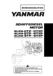
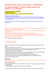
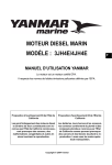
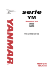
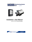
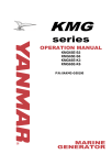
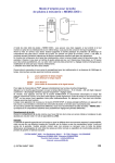
Installation & User Manual ® NMEA 2000 Gateway for Yanmar Engines Integrates with existing Yanmar B Panel MBW Technologies , LLC Email: [email protected] Phone: (267) 932.8573 x340 www.mbwtech.com EM2000X- Installation/User Manual MBW Technologies, LLC (2 – Year) Limited Warranty Electronic Modules, Displays, Cables and Connectors MBW Technologies, LLC (“MBW”) warrants its Electronic Module, Display, Electrical Cable and Connector products to be free from defects in materials and workmanship for a period of two (2) years from the date of shipment by MBW. Within this period, MBW will, at its sole option, repair or replace any Electronic Module or Display that fails in normal use and is returned to MBW (freight prepaid) within the warranty period. MBW is not responsible for charges connected with the removal of such product or reinstallation of replacement or repaired parts. This warranty does not cover failures due to abuse, misuse, accident, faulty installation or unauthorized alteration or repairs. THE EXPRESS WARRANTY SET FORTH ABOVE IS IN LIEU OF ALL OTHER WARRANTIES, EXPRESS OR IMPLIED, INCLUDING BUT NOT LIMITED TO THE IMPLIED WARRANTIES OF MERCHANTABILITY AND FITNESS FOR A PARTICULAR PURPOSE. Statements made by any person, including representatives of MBW, which are inconsistent or in conflict with the terms of this Limited Warranty, shall not be binding upon MBW unless reduced to writing and approved by an officer of MBW. IN NO EVENT SHALL MBW BE LIABLE FOR ANY INCIDENTAL, SPECIAL, INDIRECT, OR CONSEQUENTIAL DAMAGES, WHETHER RESULTING FROM THE USE, MISUSE OR INABILITY TO USE THIS PRODUCT OR FROM DEFECTS IN THE PRODUCT. Some states do not allow the exclusion of incidental or consequential damages, so the above limitation may not apply to you. MBW retains the exclusive right to repair or replace the electronic module or display or offer a full refund of the purchase price at its sole discretion. SUCH REMEDY SHALL BE YOUR SOLE AND EXCLUSIVE REMEMDY FOR ANY BREACH OF WARRANTY. NMEA 2000® is a registered trademark of the National Marine Electronics Association. Copyright 2011 MBW Technologies, LLC All Rights Reserved 2 EM2000X- Installation/User Manual Table of Contents Product Overview .......................................................................................................................................................................... 5 Components ........................................................................................................................................................................................................... 5 EM2000 Connectors .......................................................................................................................................................................................... 6 Installation ........................................................................................................................................................................................ 9 Step 1. EM2000 Mounting ............................................................................................................................................................................. 9 Step 2. Engine Connections ........................................................................................................................................................................ 10 Step 3. B Panel Connection ......................................................................................................................................................................... 10 Step 4. NMEA Network Connection........................................................................................................................................................ 10 Step 5. Auxiliary Sensor Connections (Optional) ............................................................................................................................ 10 EM2000 Operation ..................................................................................................................................................................... 11 Power ..................................................................................................................................................................................................................... 11 Alarms ................................................................................................................................................................................................................... 11 Engine Data ......................................................................................................................................................................................................... 11 Tachometer Input ............................................................................................................................................................................................ 11 Oil Pressure ......................................................................................................................................................................................................... 12 Coolant Temperature ..................................................................................................................................................................................... 12 Boost Pressure (LH/LP/LY2/CX only) .................................................................................................................................................. 13 Auxiliary Input #1............................................................................................................................................................................................ 13 Auxiliary Input #2............................................................................................................................................................................................ 13 NMEA 2000 Network Fuse ...................................................................................................................................................... 13 Factory Defaults ........................................................................................................................................................................... 14 Oil Pressure Sender Installation ........................................................................................................................................... 15 Coolant Temp Sender Installation ....................................................................................................................................... 17 NMEA 2000 Backbone Installation...................................................................................................................................... 19 Wiring Diagram ............................................................................................................................................................................ 22 3 Connector Engine Harness ...................................................................................................................................................................... 22 2 Connector Engine Harness ...................................................................................................................................................................... 23 EM2000 Connections ..................................................................................................................................................................................... 24 Technical Specifications ........................................................................................................................................................... 25 Environmental ................................................................................................................................................................................................... 25 Data Transmitted ............................................................................................................................................................................................. 25 Transmitted NMEA 2000® Parameter Groups .................................................................................................................................. 26 Appendix A – Engine Models .................................................................................................................................................. 27 Appendix B - Installation Notes: ........................................................................................................................................... 28 Copyright 2011 MBW Technologies, LLC All Rights Reserved 3 EM2000X- Installation/User Manual Copyright 2011 MBW Technologies, LLC All Rights Reserved 4 EM2000X- Installation/User Manual Product Overview The EM2000 Product (EIM) is designed as a Plug ‘N’ Play NMEA 2000 engine monitoring gateway for Yanmar Mechanical Engines. The EM2000 converts the data and alarms from your analog engine to the NMEA 2000 protocol. The engine information can then be viewed on any NMEA 2000 compliant multifunction display. The EM2000 is fully compatible with the Yanmar B panel and can be installed at the helm or in the engine room. No additional wiring is needed because the EM2000 plugs directly into your Yanmar engine harness. There is no need to purchase a separate ‘Y’ harness as this connection requirement is built into the EM2000 wiring harness. To install simply disconnect your B panel from the Yanmar engine harness. Then connect the EM2000 to the engine harness and finally the B panel to the EM2000. Connect to your NMEA network and you are ready to go. Components EM2000G EM, Eng Monitor, JH/YM, Single Eng System 1 per engine EM2000P EM, Eng Monitor, JH/YM, Port, Dual Eng System 1 per engine EM2000S EM, Eng Monitor, JH/YM, Stbd, Dual Eng System 1 per engine EM2100G EM, Eng Monitor, LP/LY2/CX, Single Eng System 1 per engine EM2100P EM, Eng Monitor, LP/LY2/CX, Port, Dual Eng System 1 per engine EM2100S EM, Eng Monitor, LP/LY2/CX, Stbd, Dual Eng System 1 per engine MN10020 Manual, Install / User, EM2000X 1 per system MN10019 Data Sheet, EM2000X Optional 1000042-00 Sender; Temperature 0-120C, 10-180Ω Optional 1000043-00 Sender; Oil Pressure, 0-10bar, 10-180Ω Optional 1000043-50 Kit; Oil Pressure, Tee, Adaptor, Sender (0-10bar) Optional 1000043-51 Hardware; Adaptor, 1/8 x 1/8 F3HGS Optional 1000043-52 Hardware; Tee, 1/8 MRO-S Optional CM100xx Harness; Devicenet, xx’ Optional CM10051 Terminator; Devicenet, Male 1 per network CM10052 Terminator; Devicenet, Female 1 per network CM10060 T; Devicenet 1 per node XX: Denotes part number option for length, position or model. Copyright 2011 MBW Technologies, LLC All Rights Reserved 5 EM2000X- Installation/User Manual EM2000 Connectors A2’ B Panel Connector A2 Engine Connector A3 Engine Connector NMEA 2K Devicenet Connector EM2000 B-Panel Connection Copyright 2011 MBW Technologies, LLC All Rights Reserved 6 CM10051 A1 CM100xx NMEA Network A2 A3 Terminator EM2000 CM10052 CM10060 Terminator Connector A1 (3 Pin) Power/Start/Glow Connector A2 (8 pin) Ignition/Ground/Alarms/Tach Connector A3 (8 pin) Oil P/Coolant Temp/Trim EM2000 Block Diagram – Single Engine EM2000X- Installation/User Manual A2 Copyright 2011 MBW Technologies, LLC All Rights Reserved 7 EM2000X- Installation/User Manual Copyright 2011 MBW Technologies, LLC All Rights Reserved 8 EM2000X- Installation/User Manual Installation Step 1. EM2000 Mounting Determine the best location for installing the EM2000 (helm or engine room). The EM2000 can be installed at either location. Final location is left to the installer based on vessel wiring and ease of access. 9/32” 4 1/2” 1 5/16” Not To Scale Copyright 2011 MBW Technologies, LLC All Rights Reserved 9 EM2000X- Installation/User Manual Step 2. Engine Connections The EM2000 has three Yanmar compatible connectors. Two of the connectors (A2 & A3) mate with the engine harness. The third (A2’) mates with the ignition panel. A2 is a plug type connector (female contacts) and provides connections for ignition, tachometer and various alarms such as; oil pressure and coolant temp. A3 is socket type connector (male contacts) and provides connections for analog senders such as oil pressure, coolant temperature and trim. The B panel does not use these inputs and therefore the EM2000 does not provide a mating B panel connector for these inputs. The EM2000 does have the capability to measure these inputs and therefore provides a mating connector via A3. Depending on your model engine the engine harness will provide a mating A3 connector. Typically all 4JH and most 3YM engines will have this mating connector as part of the engine harness. 2YM and 3YM engines will not typically have this connector. If your engine does not have a mating A3 connector oil pressure and coolant temperature will not be measured unless a wiring harness is added to your engine. Step 3. B Panel Connection The EM2000 has one B Panel compatible connector (A2’). A2’ is a plug type connector and duplicates the signal connections contained in connector A2. Plug this connector into the B panel connector. Step 4. NMEA Network Connection For connection to the NMEA 2000 network the EM2000 provides a NMEA 2000 compliant devicenet connector. This is a round 5 pin connector and connection is made to the backbone by using a CANBus devicenet Tee. If a NMEA 2000 backbone is not currently installed you will need to do so. See section NMEA 2000 Backbone Installation for more details. Step 5. Auxiliary Sensor Connections (Optional) The EM2000 has two auxiliary sensor inputs. Auxiliary input #1 is configured to measure fuel level using a 24033 ohm sender. This input connection is the pink wire. Auxiliary input #2 is configured to measure fuel level using a 240-33 ohm sender. This input connection is the pink/white wire. Both of these inputs are terminated with 0.156 DIA disconnect style connectors. These inputs may be re-configured using an M701 display or via special order. See System Default section for more information. The EM2000 does not require these inputs to be connected for proper operation. Copyright 2011 MBW Technologies, LLC All Rights Reserved 10 EM2000X- Installation/User Manual EM2000 Operation The EIM is an analog to NMEA 2000 gateway and is designed specifically for Yanmar mechanical engines. The module converts all the analog engine data to the NMEA CANBus protocol. This allows any NMEA 2000 compliant display to be used for displaying engine data. In addition to engine data two auxiliary inputs are provided for fluid level measurement. The EIM is configured at the factory per the part number specification. See Factory defaults for more details. No additional configuration is needed. Power The EM2000 is powered via system ignition. When engine ignition is activated power will be applied to the module via connector A2. Once powered the module will provide NMEA 2000 network power via a 4A fuse. Upon power up the EIM will start broadcasting NMEA data. The engine does not need to be started for network data to be broadcast. Alarms The EM2000 monitors engine generated alarms such as; oil pressure, coolant temperature, water-in-fuel, charge, coolant level and sail drive (gear alarm). All alarms will be suppressed if the engine is not running with the exception of the following alarms. They will continue to be monitored even if the engine is not running: Coolant Temperature, Water-in-Fuel and Coolant Level. Note: Water-in-Fuel and coolant level alarms are contained in connector A3 of the engine harness. Some engine models will only have 2 connectors (A1 and A2) instead of 3 connectors (A1,A2 & A3). For 2 connector engines water-in-fuel and coolant level alarms are not available. Engine Data The following engine data is measured by the EM2000: Battery Voltage, Engine Speed, Engine Hours, Oil Pressure*, Coolant Temperature* and Boost Pressure**. *Senders not installed in most 3 and 4 cylinder models. Optional sender kit required. **LP/LY2 engine only. Tachometer Input The EM2000 as shipped from the factory uses the alternator for the tachometer input. This is standard wiring for 3 and 4 cylinder model Yanmar engines. See section Factory Defaults for more information. Copyright 2011 MBW Technologies, LLC All Rights Reserved 11 EM2000X- Installation/User Manual Calibrating Tachometer The system is configured for the Yanmar standard 10.29 pulses/rev. Should the pulses/revolution value need adjusting the EM2000 provides three inputs for adjusting the tachometer calibration. These inputs are provided in the EIM harness as 0.156 DIA disconnect type connections and are labeled “RPM Up”, “RPM Down” and “RPM Common”. To increase the RPM measurement momentarily touch the RPM Up wire to RPM Common. This will increase the RPM value by 10 RPM. To decrease the RPM measurement momentarily touch the RPM Down wire to RPM Common. This will decrease the RPM value by 10 RPM. As the RPM value is increased or decreased the system instantaneously calculates the corrected pulses/rev value and stores this number into non-volatile memory for continued use. See wiring diagram section for connection details. Note: The first time tachometer calibration is used the system will create a base rpm idle value to calibrate against. This value is 820 RPM. The system will start adjusting the measured RPM value from that base RPM value. For example, if the displayed engine speed is 840 rpm and the desired rpm value is 800 rpm; the first time the rpm down connection is made the display rpm value will jump to 820 rpm as a base engine speed calibration value. All subsequent rpm adjustments will cause a +/ – 10 rpm change from the displayed value. Oil Pressure The EM2000 provides for oil pressure measurement. Should your engine have an oil pressure sender installed the EIM will convert this value to the NMEA 2000 output for display. If your engine does not have a sender installed no action is needed. The EIM will automatically sense that the sender is missing and provide a “N/A” data value to the NMEA network. If you wish to install an oil pressure sender the EIM is compatible with Yanmar sender P/N: 119773-91650. This sender has a pressure range of 0-10bar with a resistance of 10-180 ohms respectively. To install an oil pressure sender, see section “Oil Pressure Sender Installation”. Coolant Temperature The EM2000 provides for coolant temperature measurement. Should your engine have a coolant temperature sender installed the EIM will convert this value to the NMEA 2000 output for display. If your engine does not have a sender installed no action is needed. The EIM will automatically sense that the sender is missing and provide a “N/A” data value to the NMEA network. If you wish to install a coolant temperature sender the EIM is compatible with Yanmar sender P/N: 119773-91700. This sender has a pressure range of 0-120 Deg C with a resistance of 180-10 ohms respectively. To install a coolant temperature sender, see section “Coolant Temp Sender Installation”. Copyright 2011 MBW Technologies, LLC All Rights Reserved 12 EM2000X- Installation/User Manual Boost Pressure (LH/LP/LY2/CX only) The EM2000 provides for boost pressure measurement. It is common for LH/LP/LY2/CX engines to have a boost pressure sender installed from the factory and therefore the EIM will convert this value to the NMEA 2000 output for display. If your engine does not have a sender installed not action is needed. The EIM will automatically sense that the sender is missing and provide a “N/A” value to the NMEA network. If you wish to install a boost pressure sender the EIM is compatible with Yanmar sender P/N: 11977391301. This sender has a pressure range of 0-2.94 bar (0-42.6 psi) with a resistance range of 83-12 ohms respectively. Auxiliary Input #1 This input is configured for fluid level measurement. Specifically fuel level. The sender type (USA or European) and NMEA 2000 tank instance (0,1,2 or 3) is configured at the factory and is dependent on the part number ordered. See Factory Defaults section for details. Auxiliary Input #2 This input is configured for fluid level measurement. Specifically fuel level. The sender type (USA or European) and NMEA 2000 tank instance (0,1,2 or 3) is configured at the factory and is dependent on the part number ordered. See Factory Defaults section for details. NMEA 2000 Network Fuse The EM2000 provides power to the NMEA network and therefore provides a 4A fuse for protection. The fuse is a standard 4a ATC type fuse. Copyright 2011 MBW Technologies, LLC All Rights Reserved 13 EM2000X- Installation/User Manual Factory Defaults As shipped from the factory the EM2000 is configured as follows; EM2000G Engine Position Engine Model Tachometer Input Tachometer Calibration Oil Pressure Coolant Temp Auxiliary input #1 Auxiliary input #2 Engine Senders Auxiliary inputs Oil Pressure Alarm Coolant Temp Alarm Charge Alarm Sail Drive Oil Alarm Water In Fuel Alarm Trim Port engine application YM/JH Alternator (10.29 ppr) Alternator (10.29 ppr) Enabled Enabled Fuel Level (NMEA instance 0) Fuel Level (NMEA instance 1) VDO Type USA Type senders (240-33 ohms) Enabled Enabled Enabled Enabled Enabled Disabled EM2000P Engine Position Engine Model Tachometer Input Tachometer Calibration Oil Pressure Coolant Temp Auxiliary input #1 Auxiliary input #2 Engine Senders Auxiliary inputs Oil Pressure Alarm Coolant Temp Alarm Charge Alarm Sail Drive Oil Alarm Water In Fuel Alarm Trim Port engine application YM/JH Alternator (10.29 ppr) Alternator (10.29 ppr) Enabled Enabled Fuel Level (NMEA instance 0) Fuel Level (NMEA instance 2) VDO Type USA Type senders (240-33 ohms) Enabled Enabled Enabled Enabled Enabled Disabled EM2000S Engine Position Engine Model Tachometer Input Tachometer Calibration Oil Pressure Coolant Temp Auxiliary input #1 Auxiliary input #2 Engine Senders Auxiliary inputs Oil Pressure Alarm Coolant Temp Alarm Charge Alarm Sail Drive Oil Alarm Water In Fuel Alarm Trim Starboard engine application YM/JH Alternator (10.29 ppr) Alternator (10.29 ppr) Enabled Enabled Fuel Level (NMEA instance 1) Fuel Level (NMEA instance 3) VDO Type USA Type senders (240-33 ohms) Enabled Enabled Enabled Enabled Enabled Disabled Copyright 2011 MBW Technologies, LLC All Rights Reserved 14 EM2000X- Installation/User Manual Oil Pressure Sender Installation To install an oil pressure sender you will need to answer the following questions; Question 1; Does your engine have a port to install the sender? Question 2; Does your engine harness have 3 connectors? Note: If your engine only has 2 connectors (A1 & A2) oil pressure cannot be measured. Oil Pressure Sender Mounting Installing the oil pressure sender is dependent on the model engine you have. Older series engines do not have a port and require the addition of Tee and an adaptor to add the sender. Newer series engines have a port for installing the sender. An adaptor is still needed between the sender and the engine port to accommodate the pipe thread differences. Older Series Engines Copyright 2011 MBW Technologies, LLC All Rights Reserved 15 EM2000X- Installation/User Manual Newer series engines An adaptor between the oil pressure sender and the engine port is needed to accommodate the sender. See Figure below. Copyright 2011 MBW Technologies, LLC All Rights Reserved 16 EM2000X- Installation/User Manual Oil Pressure Sender Connection The engine oil pressure sender is connected to the EM2000 via connector A3. Most 3 and 4 cylinder engines have a 3 connector engine wiring harness; Connector A1 (3 position power connector) Connector A2 (8 position ignition/alarm connector) and Connector A3 (8 position analog sender connector) See Section Wiring Diagram for more details. To connect the oil pressure sender to the EM2000 attach the pre-installed Yellow/Black engine harness wire to the sender. The Yellow/White wire must be connected to the oil pressure alarm sender. This connection provides the oil pressure alarm indication for the ignition panel and EM2000. See figure to the right for wire locations. Coolant Temp Sender Installation As with the oil pressure sender the EM2000 requires a 3 connector engine harness when measuring the coolant temp sender. The connection for temp sender is made via connector A3. See Section Wiring Diagram for more details. To connect the coolant temp sender to the EM2000 attach the pre-installed White/Black engine harness wire to the sender. The White/Blue wire must be connected to the coolant temp alarm sender. This connection provides the engine overheat alarm indication for the ignition panel and EM2000. See figure to the right for wire locations. Copyright 2011 MBW Technologies, LLC All Rights Reserved 17 EM2000X- Installation/User Manual Coolant Temp Sender Mounting Most model engines have multiple locations for installing a coolant temperature sender. See Figure below for sender and wire locations. Coolant Temp Sender Connection Copyright 2011 MBW Technologies, LLC All Rights Reserved 18 EM2000X- Installation/User Manual NMEA 2000 Backbone Installation Network Basics The network consists of a single cable run (known as a backbone or trunk line) to which devices are connected to it by means of a “T” Connector. At EACH end of the single cable run is a termination resistor. The termination resistors must be installed to ensure proper network operation and reliability. Note regarding connectivity of “T” Connectors When connecting a product to the backbone always use a “T” connector. This is generally referred to as a node connection. When connecting a product to a “T” connector (drop cable) always install via the middle connection on the “T”. Copyright 2011 MBW Technologies, LLC All Rights Reserved 19 EM2000X- Installation/User Manual The network cable is a Devicenet standard cable which consists of two twisted pair wires and a shield. One twisted pair is CANBus data and the other is CANBus power. The shield protects the signal and power wires from Radio Frequency Interference (RFI) and helps to reduce the RFI transmission from the cable. The CANBus data wires are referred to as CAN Hi (white) and CAN Lo (Blue). The power wires are V+ (red) and common (black). The diagram below is an illustration of the Micro C connector pinout used on the EM2000 module. Three Devicenet cable types are available Mini, Mid and Micro. The mini cable provides the largest current carrying capacity at 8 amps. The Mid and Micro cables have a current capacity of 4 amps but the Mid cable provides larger diameter wire power wires yielding less voltage drop over the Micro cable. Network Specifications Up to 50 physical connections known as node connections. Network speed is 250K baud Maximum drop cable length is 6 meters (20’). Maximum current draw per node is 1 amp. Backbone maximum length for Mini C cable is 200 meters (656’). Backbone maximum length for Mid and Micro C cable is 100 meters (328’). Each network needs 2 and ONLY 2 terminators (one male and one female). Network voltage 9-16volts. Copyright 2011 MBW Technologies, LLC All Rights Reserved 20 EM2000X- Installation/User Manual Network Power The CANBus requires a nominal 12v of DC power for network operation. Do not connect your network to 24v. The Micro C CANBus cable has a modest wire gauge (22AWG) and therefore is subject to voltage loss when large backbones are installed. As the backbone cable length increases so does the cable resistance. This causes a loss in voltage across the length of the cable. This loss increases as more nodes are connected to the network. Each NMEA2K device must specify a Load Equivalency Number (LEN). The combination of cable type and total network load (addition of all LEN values) will determine backbone length. See guide below for typical backbone lengths using Micro C cable and a nominal network voltage of 12 volts. LEN Network Length LEN Network Length 5 300’ (91M) 13 120’ (36M) 6 260’ (79M) 15 100’ (31M) 7 220’ (67M) 18 80’ (24M) 8 200’ (61M) 23 60’ (18M) 9 180’ (55M) 32 40’ (12M) 10 160’ (49M) 50 20’ (6M) 11 140’ (43M) 80 <10’ (<3M) The LEN value for the EM2000 is 1. Typically a backbone installation with one EM2000 module and two Multifunction color displays can support a network length up to 76 meters (250’) without requiring additional power. When connected to the NMEA 2000 network the EM2000 product provides the necessary power for network operation. No additional power wiring is needed. The EM2000 provides a 4A fused connection for the network power. Note: Should the your network length exceed the rated LEN value in the table above you many need to provide a second source of network power. Copyright 2011 MBW Technologies, LLC All Rights Reserved 21 EM2000X- Installation/User Manual Wiring Diagram 3 Connector Engine Harness Connector A1 Pin Number Description Wire Color 1 Start White 2 Power Red 3 Air Heaters (Glow) Blue Connector A2 Pin Number Description Wire Color 1 Engine Ground Black 2 Not Used 3 Alarm, High Coolant Temp White/Blue 4 Alarm, Low Oil Pressure Yellow/White 5 Ignition Red/Black 6 Charge Blue/Black 7 Sender, Tachometer Orange 8 Alarm, Gear Oil Yellow/Green Connector A3 Pin Number Description Wire Color 1 Sender, Coolant Temp White/Black 2 Not Used 3 Not Used 4 Alarm, Coolant Level White/Red 5 Alarm, Water-in-Fuel Green/Red 6 Sender, Trim Green 7 Sender, Boost Green/Black 8 Sender, Oil Pressure Yellow/Black Copyright 2011 MBW Technologies, LLC All Rights Reserved 22 EM2000X- Installation/User Manual 2 Connector Engine Harness Connector A1 Pin Number Description Wire Color 1 Start White 2 Power Red 3 Air Heaters (Glow) Blue Connector A2 Pin Number Description Wire Color 1 Engine Ground Black 2 Not Used 3 Alarm, High Coolant Temp White/Blue 4 Alarm, Low Oil Pressure Yellow/White 5 Ignition Red/Black 6 Charge Blue/Black 7 Sender, Tachometer Orange 8 Alarm, Gear Oil Yellow/Green Copyright 2011 MBW Technologies, LLC All Rights Reserved 23 EM2000X- Installation/User Manual EM2000 Connections Connector A2 – connects to engine harness Pin Number Description Wire Color 1 Engine Ground Black 2 Not Used 3 Alarm, High Coolant Temp White/Blue 4 Alarm, Low Oil Pressure Yellow/White 5 Ignition Red/Black 6 Charge Blue/Black 7 Sender, Tachometer Orange 8 Alarm, Gear Oil Yellow/Green Connector A2’ – connects to Yanmar Ignition Panel (B Panel) Pin Number Description Wire Color 1 Engine Ground Black 2 Not Used 3 Alarm, High Coolant Temp White/Blue 4 Alarm, Low Oil Pressure Yellow/White 5 Ignition Red/Black 6 Charge Blue/Black 7 Sender, Tachometer Orange 8 Alarm, Gear Oil Yellow/Green Connector A3 – connects to engine harness Pin Number Description Wire Color 1 Sender, Coolant Temp White/Black 2 Not Used 3 Not Used 4 Alarm, Coolant Level White/Red 5 Alarm, Water-in-Fuel Green/Red 6 Sender, Trim Green 7 Sender, Boost Green/Black 8 Sender, Oil Pressure Yellow/Black Auxiliary Inputs – Disconnect 0.156 DIA Female Description Wire Color Auxiliary Input #1 – Fluid level (240-33 ohms) Pink Auxiliary Input #2 – Fluid level (240-33 ohms) Pink/White RPM Calibrate Common Black RPM Up Brown RPM Down Brown/White Copyright 2011 MBW Technologies, LLC All Rights Reserved 24 EM2000X- Installation/User Manual Technical Specifications Environmental Operating Voltage 6 to 16 VDC Operating Temperature -18C to +77C Storage Temperature -40C to +85C Power Consumption - operating <50mA @ 12VDC NMEA LEN Value 1 Power Consumption – power down <100uA Vibration ABYC P-24 Communication NMEA 2000® Humidity Test 100 Hours +77C @ 90-95% Rel. Humidity Transient Voltage Test SAE J1113-12 Protection IP67 Corrosion / Salt Spray 300 hrs per ASTM B117 EMI Emissions ABYC P-24 EMI Immunity ABYC P-24 Dimensions (base unit not including harness) 117mm x 115mm x (4.63” x 4.50” x 1.38”) 35mm Data Transmitted Input Measured Engine Speed Oil Pressure* Coolant Temperature* Engine Hours Battery Voltage Boost Pressure** Engine Trim** Rudder Angle*** Fuel Level Water Level*** Waste Level*** Alarms Oil Pressure Alarm Coolant Temperature Alarm System Charge Alarm Transmission Oil Alarm Coolant Level Alarm Water-in-Fuel Alarm Low Voltage Alarm *Sender required on certain engine models. **LP/LY2/LH/CX Engine Models ***Requires Special Part Number (call for information) Copyright 2011 MBW Technologies, LLC All Rights Reserved 25 EM2000X- Installation/User Manual The EIM will automatically transmit data to the network if a sender is connected. When a sender is not connected the data message will not be transmitted. Per the NMEA standard, if the data message contains several types of engine data (i.e. PGN127489) the missing sender data will be transmitted as “Not Available”. Transmitted NMEA 2000® Parameter Groups PGN 127488 PGN 127489 PGN 127493 PGN 127245 PGN127505 PGN 127508 Engine Parameters, Rapid Update Engine Parameters, Dynamic Transmission Parameters, Dynamic Rudder Fluid Level Battery Status Proprietary PGN Maintenance Timer All Configuration Messaging Copyright 2011 MBW Technologies, LLC All Rights Reserved 26 EM2000X- Installation/User Manual Appendix A – Engine Models The table below lists the various Yanmar engine model numbers and their factory default harness configuration. Model Engine Harness 2YM15 3YM20 3YM30 JH3 Series 4JH3-T 4JH3-TE 4JH3-HTE JH4 Series 2 connector 2 connector 2 connector Note See note 1 See note 1 See note 1 3 connector 3 connector 3 connector See note 3 See note 3 See note 3 3JH4E 4JH4E 4JH4-AE 4JH4-TE 4JH4-HTE JH5 Series 3 connector 3 connector 3 connector 3 connector 3 connector See note 2 See note 2 See note 2 See note 2 See note 2 3JH5E 4JH5E LH Series 3 connector 3 connector See note 2 See note 2 4LHA-HTP 4LHA-DTP 4LHA-STP LP Series 3 connector 3 connector 3 connector See note 2 See note 2 See note 2 6LPA-DTP 6LPA-STP 6LP-STE 3 connector 3 connector 3 connector See note 4 See note 4 See note 4 To install oil pressure or coolant temperature senders the following may apply; Note 1: An engine with a 2 connector harness will need to install the third connector (A3 - analog sender connector) to attach the desired senders. These engines will also need adaptor plumbing to add the desired senders. Note 2: The engine has the third connector (connector A3) installed. These engines also have plumbing installed to attach the senders. Senders optional. Note 3: The engine has the third connector (A3) installed. These engines require additional plumbing fixtures to install the senders. Note 4: The engine has the third connector (A3) installed. Sender installed by factory. *Should your engine have been installed with a Yanmar ‘C’ Panel it is likely that one or both the oil pressure and coolant temperature senders were previously installed. The EM2000 is not compatible with a Yanmar ‘C’ Panel. Copyright 2011 MBW Technologies, LLC All Rights Reserved 27 EM2000X- Installation/User Manual Appendix B - Installation Notes: Existing Installation: Engine Model: Ignition Panel: System Voltage: Number of Engines: Number of Stations: USA or European Install: Display / Gauge Type: Auxiliary #1 Fluid Tank: Auxiliary #2 Fluid Tank: Oil Pressure Sender Installed: Coolant Temp Sender Installed: Water-in-Fuel Alarm: Existing Network: Sail Drive Connected: Engine Hours: Copyright 2011 MBW Technologies, LLC All Rights Reserved 28 EM2000X- Installation/User Manual MBW Technologies, LLC 2080 Detwiler Rd. Suite 1 Harleysville, PA 19438 Sales: (267) 932-8573 x340 Support: (267) 93208573 x341 Email: [email protected] Email: [email protected] OR Contact your local Yanmar Dealer P/N MN10020-50 Copyright 2011 MBW Technologies, LLC All Rights Reserved 29