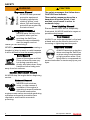
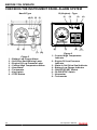
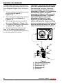
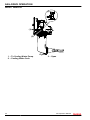
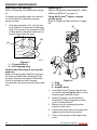
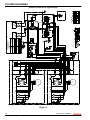
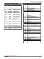
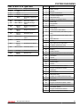
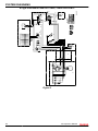
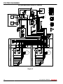
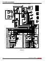
1
Sail-Drive
OPERATION MANUAL
SD20
SD50
SD50-4T
P/N: 0ASDM-G00101
SAILDRIVE
Disclaimers:
All information, illustrations and specifications in this manual are based on the latest
information available at the time of publishing. The illustrations used in this manual are
intended as representative reference views only. Moreover, because of our continuous
product improvement policy, we may modify information, illustrations and / or specifications
to explain and / or exemplify a product, service or maintenance improvement. We reserve
the right to make any change at any time without notice. Yanmar and
are
registered trademarks of Yanmar Co., Ltd. in Japan, the United States and / or other
countries.
All Rights Reserved:
No part of this publication may be reproduced or used in any form by any means - graphic,
electronic, or mechanical, including photocopying, recording, taping, or information storage
and retrieval systems - without the written permission of Yanmar Marine International.
© 2009 Yanmar Marine International
0309
ii
SD Operation Manual
© 2009 Yanmar Marine International
TABLE OF
CONTENTS
Page
Introduction......................................................................1
Safety...............................................................................3
Safety Precautions.........................................................3
General Information ................................................. 4
Before You Operate ................................................. 4
During Operation and Maintenance ............................. 5
Product Overview..............................................................9
Overview......................................................................9
Owner / Operator Responsibilities ............................... 9
New Sail-Drive Break-In: ........................................... 9
Dealer / Distributor Responsibilities ............................. 9
Component Identification...............................................10
Galvanic Corrosion.......................................................11
Corrosion Control.........................................................11
Shore Power...............................................................12
Underwater Drive Coating..............................................13
Before You Operate..........................................................15
Propeller Selection.......................................................16
Recommended Propeller Size (Maximum) .................. 16
Fitting a Fixed Propeller (2-Blade) ............................. 17
Lubricating Oil.............................................................18
Filling With Lubricating Oil - SD20, SD50 and SD50-4T.........19
Checking the Instrument Panel Alarm System.....................20
Daily Checks...............................................................23
Visual Checks....................................................... 23
Sail-Drive Operation.........................................................25
Remote Control Device Check........................................26
SD20 .................................................................. 26
SD50 / SD50-4T.................................................... 28
Engine Cooling Water...................................................29
SD20 .................................................................. 29
SD Operation Manual
iii
© 2009 Yanmar Marine International
TABLE OF CONTENTS
SD50 / SD50-4T.................................................... 30
Periodic Maintenance.......................................................31
Tightening Fasteners....................................................33
Torque Charts.............................................................34
Standard Torque Values ......................................... 34
Standard Torque Chart ........................................... 34
Periodic Maintenance............................................. 35
Periodic Maintenance Table...........................................36
When The Vessel Is Out Of The Water, Perform The
Following:...................................................................38
Removing Deposits From The Lower Gear Case .......... 38
Repairing Damaged Coating .................................... 38
Inspecting the Anode.............................................. 38
Inspecting The Folding Propeller............................... 38
Draining Water...................................................... 38
Periodic Maintenance Procedures....................................39
After Initial 50 Hours of Operation.............................. 39
Every 100 Hours of Operation .................................. 48
Every 250 Hours of Operation .................................. 49
Every 500 Hours of Operation .................................. 49
Every Year ........................................................... 50
Every 2000 Hours of Operation................................. 51
Every 5 Years ....................................................... 51
Specifications..................................................................53
System Diagrams.............................................................55
Maintenance Log.........................................................80
iv
SD Operation Manual
© 2009 Yanmar Marine International
INTRODUCTION
This Operation Manual describes Sail-Drive Models SD20, SD50, SD50-4T. For engine
handling and operation, refer to the respective operation manuals for Engine Models
1GM10C, 2YM15, 3YM20, 3YM30, 3JH4CE, 3JH5CE, 4JH4ACE, 4JH5CE and 4JH4-TCE.
However, instructions for the marine gear box are not necessary as they are included.
Engines and Sail-Drive combinations are available as follows:
Engine model
Sail-Drive Model
1GM10C
SD20
2YM15
3YM20, 3YM30
3JH4CE
3JH5CE
SD50
4JH4ACE
4JH5CE
4JH4-TCE
SD50-4T
SD Operation Manual
1
© 2009 Yanmar Marine International
INTRODUCTION
This Page Intentionally Left Blank
2
SD Operation Manual
© 2009 Yanmar Marine International
SAFETY
Yanmar considers safety of great
importance and recommends that anyone
that comes into close contact with its
products, such as those who install,
operate, maintain or service Yanmar
products, exercise care, common sense
and comply with the safety information in
this manual.
!
This safety alert symbol appears
with most safety statements. It
means attention, become alert,
your safety is involved! Please
read and abide by the message
that follows the safety alert
symbol.
SAFETY PRECAUTIONS
DANGER
Indicates a hazardous situation which, if
not avoided, will result in death or
serious injury.
WARNING
Indicates a hazardous situation which, if
not avoided, could result in death or
serious injury.
CAUTION
Indicates a hazardous situation which, if
not avoided, could result in minor or
moderate injury.
NOTICE
Indicates a situation which can cause
damage to the Sail-Drive, personal property
and / or the environment or cause the
equipment to operate improperly.
SD Operation Manual
3
© 2009 Yanmar Marine International
SAFETY
General Information
There is no substitute for common sense
and careful practices. Improper practices or
carelessness can cause burns, cuts,
mutilation, asphyxiation, other bodily injury
or death. This information contains general
safety precautions and guidelines that must
be followed to reduce risk to personal safety.
Special safety precautions are listed in
specific procedures. Read and understand
all of the safety precautions before operation
or performing repairs or maintenance.
Before You Operate
DANGER
The safety messages that follow have
DANGER level hazards. These safety
messages describe a hazardous
situation which, if not avoided, will
result in death or serious injury.
NEVER permit anyone to
install or operate the SailDrive without proper training.
• Read and understand this Operation
Manual before you operate or service the
Sail-Drive to ensure that you follow safe
operating practices and maintenance
procedures.
• Safety signs and labels are additional
reminders for safe operating and
maintenance techniques.
• See your authorized Yanmar marine
dealer or distributor for additional training.
Crush Hazard
NEVER stand under a hoisted
Sail-Drive.
If the hoist mechanism fails,
the Sail-Drive will fall on you.
When you need to transport a
Sail-Drive for repair, have a helper assist
you to attach it to a hoist and load it onto a
truck.
NEVER support Sail-Drive with equipment
not designed to support the weight of the
Sail-Drive such as wood blocks or by only
using a jack.
NEVER use the Sail-Drive lifting eye to lift
the engine and Sail-Drive as an assembly.
Use the engine lifting eyes to lift the engine
and Sail-Drive. Only use the Sail-Drive lifting
eye to lift the Sail-Drive as a separate
component.
4
SD Operation Manual
© 2009 Yanmar Marine International
SAFETY
During Operation and
Maintenance
WARNING
The safety messages that follow have
WARNING level hazards.
DANGER
The safety messages that follow have
DANGER level hazards.
Explosion Hazard
While the engine is running or
the battery is charging,
hydrogen gas is being
produced and can be easily
ignited. Keep the area around
the battery well-ventilated and keep sparks,
open flame and any other form of ignition out
of the area.
Fire Hazard
Ensure that appropriate fire
detection and extinguishing
equipment are installed and
checked periodically for
proper operation.
These safety messages describe a
hazardous situation which, if not
avoided, could result in death or serious
injury.
Fire Hazard
Undersized wiring systems
can cause an electrical fire.
Sever Hazard
NEVER service the Sail-Drive
while under tow or if the
engine is running at idle
speed. The propeller may
rotate under these
circumstances.
Alcohol and Drug Hazard
NEVER operate the engine
while under the influence of
alcohol or drugs or when
feeling ill.
SD Operation Manual
5
© 2009 Yanmar Marine International
SAFETY
CAUTION
WARNING
Exposure Hazard
ALWAYS wear personal
protective equipment
including appropriate
clothing, gloves, work
shoes, eye and hearing
protection as required by
the task at hand.
Entanglement Hazard
NEVER leave the key in the
key switch when you are
servicing the Sail-Drive.
Someone may accidentally
start the engine and not
realize you are servicing it.
NEVER operate the engine while wearing a
headset to listen to music or radio because
it will be difficult to hear the warning signals.
Burn Hazard
Some of the engine and SailDrive surfaces become very
hot during operation and
shortly after shut-down. Keep
hands and other body parts
away from hot surfaces.
The safety messages that follow have
CAUTION level hazards.
These safety messages describe a
hazardous situation which, if not
avoided, could result in minor to
moderate injury.
Poor Lighting Hazard
Ensure that the work area is adequately
illuminated. ALWAYS install wire cages on
portable safety lamps.
Tool Hazard
ALWAYS use tools appropriate for the task
at hand and use the correct size tool for
loosening or tightening machine parts.
Exposure Hazard
ALWAYS wear eye protection
when servicing the Sail-Drive
or when using compressed air
or high-pressure water. Dust,
flying debris, compressed air,
pressurized water or steam may injure your
eyes.
Sudden Movement Hazard
ALWAYS stop the engine before beginning
service.
Exhaust Hazard
NEVER block windows,
vents, or other means of
ventilation if the engine is
operating in an enclosed area.
All internal combustion
engines create carbon monoxide gas during
operation and special precautions are
required to avoid carbon monoxide
poisoning.
6
SD Operation Manual
© 2009 Yanmar Marine International
SAFETY
NOTICE
These notices describe a situation
which, if not avoided, can cause damage
to the Sail-Drive, personal property and /
or the environment or cause equipment
to operate improperly.
It is important to perform daily checks as
listed in this Operation Manual.
Periodic maintenance prevents unexpected
downtime, reduces the number of accidents
due to poor Sail-Drive performance and can
help extend the life of the Sail-Drive and
engine.
ALWAYS be environmentally
responsible.
The anode of the Sail-Drive is only
calculated for the Sail-Drive. Changing the
material of the propeller may require
additional anodes to be installed on the saildrive.
Failure to use the correct anode material
may result in inadequate protection and
excessive corrosion of underwater drive
system components. Use only zinc or
aluminum anodes in brackish and saltwater
applications. In freshwater applications, use
aluminum or magnesium anodes for best
results. NEVER use magnesium anodes in
brackish or salt water, as they will
deteriorate rapidly, which will lead to severe
damage to the drive system.
Follow the guidelines of the
EPA or other governmental
agencies for the proper
disposal of hazardous materials such as
lubrication oil, diesel fuel and engine
coolant. Consult the local authorities or
reclamation facility.
NEVER dispose of hazardous materials by
dumping them into a sewer, on the ground
or into ground water or waterways.
NEVER attempt to modify the Sail-Drive’s
design or safety features.
• NEVER release or modify the limiting
devices such as the engine speed limit,
fuel injection limit, etc.
• Modification will impair the safety and
performance of the product and shorten
product life.
• Modifications to the design, safety or
limiting features will void the warranty.
If the Sail-Drive oil temperature is too high,
stop engine immediately and check the SailDrive oil level and check the oil cooler for
proper coolant and water flow.
SD Operation Manual
7
© 2009 Yanmar Marine International
SAFETY
This Page Intentionally Left Blank
8
SD Operation Manual
© 2009 Yanmar Marine International
PRODUCT OVERVIEW
OVERVIEW
New Sail-Drive Break-In:
Owner / Operator
Responsibilities
The operator must, and assumes all
responsibility to:
• Read and understand the operation
manual prior to operating the sail-drive;
• Perform all safety checks as necessary to
ensure safe operation;
• Comply with and follow all lubrication and
maintenance instructions and
recommendations; and
• Have an authorized Yanmar dealer /
distributor perform periodic checkups.
Conducting normal maintenance service
and replacing consumable parts as
necessary is the responsibility of the owner /
operator and necessary to provide the best
durability, performance and dependability of
the Sail-Drive while keeping your overall
operating expenses to a minimum.
Individual operating habits and usage may
increase the frequency of performing
maintenance service condition. Monitor
conditions frequently to determine if the
maintenance intervals suggested in the
manual are frequent enough for your SailDrive.
• On the initial engine start-up, allow the
engine to idle for approximately 15
minutes while you check for proper SailDrive function and Sail-Drive oil leaks.
• During the break-in period, carefully
observe Sail-Drive seal indicators for
proper Sail-Drive function.
• During the break-in period, check the SailDrive oil levels frequently.
Dealer / Distributor
Responsibilities
In general, a dealer's responsibilities to the
customer include predelivery inspection
and preparation such as:
• Ensure that the vessel is properly
equipped.
• Prior to delivery, make certain that the
Yanmar Sail-Drive and other equipment
are in proper operating condition.
• Make all necessary adjustments for
maximum efficiency.
• Familiarize the customer with the on-board
equipment.
• Explain and demonstrate the operation of
the Sail-Drive and vessel.
SD Operation Manual
9
© 2009 Yanmar Marine International
PRODUCT OVERVIEW
COMPONENT IDENTIFICATION
(2)
(1)
(7)
(3)
(6)
(4)
(5)
0006440
1
2
3
4
–
–
–
–
Dipstick
Upper Gear Case
Lower Gear Case
Lubricating Oil Drain Plug
Figure 1
5 – Propeller
6 – Seawater Inlet
7 – Flexible Mount
10
SD Operation Manual
© 2009 Yanmar Marine International
PRODUCT OVERVIEW
GALVANIC CORROSION
CORROSION CONTROL
Galvanic corrosion results whenever two or
more dissimilar metals (like those found on
the sail-drive) are submerged in a
conductive solution, such as saltwater,
polluted water or water with a high mineral
content because a chemical reaction takes
place causing electrical current to flow
between the metals. The electrical current
flow causes the metal that is most
chemically active, or anodic, to erode. If not
controlled, galvanic corrosion may corrode
Sail-Drive components.
It is the boat designer’s responsibility and/or
the re-powering engineer’s responsibility to
design the proper systems and equipment
to control and reduce the possibility of
galvanic corrosion.
However, it is essential that the owner/
operator frequently monitor the anodes for
wear, inspect the sail-drive for corrosion and
replace the anodes often enough to provide
a sacrificial surface for the electrical current
to attack. Galvanic isolators and isolation
transformers are also available from the
aftermarket (not supplied by Yanmar). The
Galvanic isolator is a device that is installed
in series with the (AC) grounding (GREEN)
conductor of the shore-power cable to
effectively block low-voltage DC galvanic
current flow but permit the passage of
alternating current (AC) *.
The rate of corrosion depends on numerous
factors, such as:
• the number, size and location of sacrificial
anodes on the sail-drive and vessel;
• the marina environment, such as stray
current in the water, fresh or salt water and
use and isolation of shore power;
• improper application of marine paint or
antifouling paint;
• failure to repaint damaged areas; and
• how the vessel is bonded.
Please check with the boat builder, dealer or
other professional to determine if your
vessel and/or Sail-Drive is adequately
protected from galvanic corrosion.
NOTICE: The anode of the Sail-Drive is only
calculated for the Sail-Drive. Changing the
material of the propeller may require
additional anodes to be installed on the SailDrive.
*
“The Boatowner's Guide to Corrosion”, by Everett Collier.
SD Operation Manual
11
© 2009 Yanmar Marine International
PRODUCT OVERVIEW
NOTICE: Failure to use the correct anode
material may result in inadequate protection
and excessive corrosion of underwater drive
system components. Use only zinc or
aluminum anodes in brackish and saltwater
applications. In freshwater applications, use
aluminum or magnesium anodes for best
results. NEVER use magnesium anodes in
brackish or salt water, as they will
deteriorate rapidly, which will lead to severe
damage to the drive system.
SHORE POWER
If sacrificial anodes erode quickly or if signs
of corrosion are evident, the owner should
take immediate corrective action. Yanmar
recommends consulting an engineer
specializing in marine electricity and
corrosion control to determine the best way
to correct the rapid erosion of the anodes.
NOTICE: If the AC shore power ground is
not isolated from the boat ground, sacrificial
anodes may be unable to neutralize the
increased galvanic potential. Corrosion
damage that results from the improper
system design or application is not covered
by the Yanmar Limited Warranty.
Vessels that are connected to shore power
require additional protection to prevent
destructive low voltage galvanic currents
from passing through the shore power
ground wire. Galvanic isolators are available
from the aftermarket (not supplied by
Yanmar) to block these currents while still
providing a path to ground for dangerous
shock currents.
12
SD Operation Manual
© 2009 Yanmar Marine International
PRODUCT OVERVIEW
UNDERWATER DRIVE
COATING
The lower gear case coating may be
damaged when hit by objects in the water,
or when having deposits removed from it.
The underwater coating must be inspected
at least once per year and when it is believed
that an object was hit that may have caused
damage. Repair and repaint damaged
areas immediately.
Observe the following precautions when
applying antifouling or marine paint to the
bottom of the boat hull:
• ALWAYS follow the paint/coating
manufacturer's directions for surface
preparation and application.
• ALWAYS use a high quality primer and
topcoat paint specifically designed for
aluminum outboards, Sail-Drives or SternDrives.
• NEVER paint the sacrificial anodes
installed on the Sail-Drive.
• NEVER paint the Sail-Drive with a material
that contains copper or tin.
• NEVER paint over drain holes, sacrificial
anodes, or other items specified by the
sacrificial anode Manufacturer.
Contact your authorized Yanmar Marine
dealer or distributor for assistance.
NOTICE: Galvanic corrosion damage,
normal maintenance and consumable parts
are not covered by the Yanmar Limited
Warranty.
SD Operation Manual
13
© 2009 Yanmar Marine International
PRODUCT OVERVIEW
This Page Intentionally Left Blank
14
SD Operation Manual
© 2009 Yanmar Marine International
BEFORE YOU OPERATE
This section of the Operation Manual
describes propeller selection, propeller
fitting, lubricating oil specifications and how
to replenish them. It also describes the daily
instrument panel and remote-control device
checks.
Before you operate the Sail-Drive, review
the Safety section on page 3.
SD Operation Manual
15
© 2009 Yanmar Marine International
BEFORE YOU OPERATE
PROPELLER SELECTION
Recommended Propeller Size (Maximum)
Engine Model
Sail-Drive Model
1GM10C
2YM15
3YM20
SD20
Folding Type
Diameter
2-Blade Fixed Type
Diameter
14 in.
14 in.
14.5 in.
15 in.
15 in.
16 in.
16 in.
16.5 in.
SD50
18 in.
18 in.
SD50-4T
18 in.
18 in.
3YM30
3JH4CE
3JH5CE
4JH4ACE
4JH5CE
4JH4–TCE
NOTICE: Make sure the propeller (fixed or
folding) has a rubber bushing. If a propeller
is used without a rubber bushing, the shaft,
bearing and gears of the Sail-Drive will be
damaged.
16
SD Operation Manual
© 2009 Yanmar Marine International
BEFORE YOU OPERATE
Fitting a Fixed Propeller (2-Blade)
(1)
(4)
(5)
(6)
(3)
(2)
0005446
Figure 1
1 – Spacer
2 – Grease
3 – Propeller
4 – Washer
5 – Nut *
6 – Bolt **
Size
Tightening Torque
*
M16 (SD20)
M20 (SD50, SD50-4T)
60 to 70 N·m (44 to 52 lb-ft)
80 to 100 N·m (59 to 74 lb-ft)
**
M8 x 75 mm
11 to 15 N·m (8 to 11 lb-ft)
Locking Procedure for Fixed Propeller Nut (Optional)
When tightening the nut to 60 to 70 N·m (44 to 52 lb-ft) torque for the SD20, and
80 to 100 N·m (59 to 74 lb-ft) torque for the SD50 and SD50-4T, move the shift lever to ahead
and hold the crankshaft V-pulley clamp nut with a wrench to stop the propeller rotating.
SD Operation Manual
17
© 2009 Yanmar Marine International
BEFORE YOU OPERATE
LUBRICATING OIL
The choice of lubricating oil is very important. If an unsuitable oil is used, or an oil change is
neglected, it may result in damage and reduce the life of the Sail-Drive. When selecting a
lubricating oil, use one of the following:
Lubricating Oil Chart
GM, YM
Engine
series
Engine
model
1GM10C
2YM15, 3YM20, 3YM30
3JH4E, 3JH5E, 4JH4AE, 4JH5E
4JH4-TE
SD20
SD20
SD50
SD50-4T
API CC or
greater
and SAE
10W30
API GL4 or GL5 and SAE
80W90 or 90
Sail-Drive
model
Lubricating
oil for the
Sail-Drive
JH3, JH4, JH5
QuickSilver® High Performance Gear Oil
Use only oil of quality GL-4 or GL-5 in the API service, and SAE No. 90 or 80W90. (Except
model SD20 x 1GM10C & SD50 / SD50-4T).
Use only oil of quality CC or greater in the API service, and SAE No. 10W30. (Applicable
model: SD20 x 1GM10C).
For SD20 (except if coupled with the 1GM10C)
Supplier
Brand Name
API Service
SAE No.
SHELL
Shell Spilax oil EP 90
GL-4
90
SHELL
Shell Spilax oil HD 90
GL-5
90
CALTEX
Multipurpose thuban EP
GL-4/GL-59
90
MOBIL
Mobilub HD 80W-90
GL-5
80W-90
ESSO
Esso gear oil GP 90
GL-4
90
ESSO
Esso gear oil GX 90
GL-5
90
Use QuickSilver® * High Performance Gear Oil for the SD50 / SD50-4T.
*
QuickSilver® is a registered trademark of Brunswick Corporation.
18
SD Operation Manual
© 2009 Yanmar Marine International
BEFORE YOU OPERATE
FILLING WITH
LUBRICATING OIL - SD20,
SD50 AND SD50-4T
Sail-Drive
model
SD20
SD50, SD50-4T
Standard
unit
2.2 L
(2.3 qt)
2.2 L (2.3 qt)
Long-reach
unit
2.5 L
(2.6 qt)
2.35 L (2.5 qt)
Extension 58
2.45 L (2.6 qt)
Extension 100
SD20
(1)
(2)
Figure 3
1 – Oil Supply Port
2 – Oil Capacity Nameplate
0005441
SD50/SD50-4T
NOTICE: The lubricating oil capacity of the
standard unit is different from that of the
long-reach unit. Confirm the capacity by
means of the oil capacity nameplate.
1. Remove the dipstick (yellow cap). Fill
with approved lubricating oil.
2. Check the amount of lubricating oil by
inserting the dipstick as far as possible.
Do not screw the dipstick in
(Figure 3, (1)). The oil level should
reach the upper mark on the dipstick
(Figure 3, (2)).
NOTICE: It takes about 10 minutes to fill up
the Sail-Drive with lubricating oil. Check the
oil level 15 minutes after adding the
specified quantity of oil.
(1)
(2)
Figure 4
1 – Oil Supply Port
2 – Oil Capacity Nameplate
0005574
(1)
(2)
(3)
0005573
Figure 2
1 – Dipstick
2 – Upper Limit
3 – Lower Limit
SD Operation Manual
19
© 2009 Yanmar Marine International
BEFORE YOU OPERATE
CHECKING THE INSTRUMENT PANEL ALARM SYSTEM
B (Keyless) - Type
New B-Type
(1)
(4) (3) (2) (1)
20
10
(8)
(6)
(7) (8)
0000472SD
1
2
3
4
5
6
7
8
–
–
–
–
–
–
–
–
Figure 5
Battery Low Charge Alarm
Sail-Drive Seal Warning Lamp
Engine Oil Low Pressure Lamp
Coolant High Temperature Alarm
Hour Meter
Tachometer
Key Switch
STOP Button
(3)
(4)
30
40
0
(5)
(2)
50
(7)
(6)
(5)
026102-00X
Figure 6
1 – Coolant High Temperature
Indicator
2 – Engine Oil Low Pressure
Indicator
3 – Water in Sail Drive Seal Indicator
4 – Battery Low Charge Indicator
5 – ON/OFF/START Switch
6 – GLOW/STOP Switch
7 – Hourmeter
8 – Tachometer
20
SD Operation Manual
© 2009 Yanmar Marine International
BEFORE YOU OPERATE
New C-Type
(4) (3) (2) (1)
(5) (11)
(6) (12)
(7)
(8)
(9) (10)
0000473SD
Figure 7
1 – Battery Low Charge Alarm
2 – Sail-Drive Seal Warning Lamp
3 – Fuel Filter Warning Lamp
4 – Seawater Insufficient Flow Alarm
5 – Coolant Temperature Gauge
6 – Engine Oil Pressure Gauge
7 – Hour Meter
8 – Tachometer
9 – Key Switch
10–STOP Button
11–Coolant High Temperature
Warning Lamp
12–Engine Oil Low Pressure
Warning Lamp
C (Keyless) - Type
(1)
(2)
(12)
(11) (10)
(3)
(9)
(4)
(5)
(6)
(8) (7)
026103-00X
Figure 8
1 – Coolant High Temperature
Indicator
2 – Coolant Temperature Gauge
3 – Not Used On This Engine
4 – Water in Fuel Filter Indicator
5 – Water in Sail Drive Charge
Indicator
6 – Battery Low Charge Indicator
7 – ON/OFF/START Switch
8 – GLOW/STOP Switch
9 – Hourmeter
10–Tachometer
11–Engine Oil Pressure Gauge
12–Engine Oil Low Pressure
Indicator
SD Operation Manual
21
© 2009 Yanmar Marine International
BEFORE YOU OPERATE
Turn the battery switch on. Turn the key to
the ON position and check the lamps on the
panel (Figure 5, Figure 7) with the engine
off:
1. The lubricating oil warning lamp should
be illuminated (Figure 5, 3,
Figure 7, 6) .
2. The cooling water temperature warning
lamp should be out (Figure 5, 4,
Figure 7, 5) .
3. The charge warning lamp should be
illuminated (Figure 5, 1, Figure 7, 1) .
4. The rubber seal warning lamp should be
out (Figure 5, 2, Figure 7, 2) .
5. The warning buzzer should sound.
Note: All the above alarm signals will
continue until you push the starting button or
turn the key to the OFF position.
WARNING! The rubber seal alarm lamp
warns of seawater entering the vessel.
The watertight structure of the SailDrive is dual type. Even if the rubber
diaphragm A (Figure 9, (5)) is damaged
and seawater enters, the rubber
diaphragm B (Figure 9, (4)) prevents it
from entering the vessel. The rubber
seal switch between the rubber
diaphragms (Figure 9, (5)) and
(Figure 9, (4)) sounds the warning
buzzer and lights the rubber seal lamp
on the instrument panel. If this happens,
stop the engine and under sail, quickly
return to the nearest port for repairs.
(1)
(3)
(2)
(4)
(5)
019410-01X
1
2
3
4
5
–
–
–
–
–
Figure 9
ON (Rubber Seal Lamp)
Rubber Seal Switch
Diaphragm (B)
Diaphragm (A)
Seawater
22
SD Operation Manual
© 2009 Yanmar Marine International
BEFORE YOU OPERATE
DAILY CHECKS
Before starting the Sail-Drive, make sure it
is in good operating condition. Make sure
you check the following items:
Visual Checks
1. Check for damaged or missing parts.
2. Check for loose, missing or damaged
fasteners.
3. Check oil level. See Filling With
Lubricating Oil - SD20, SD50 and
SD50-4T on page 19.
4. Open cooling water cock before
operation. Drain cooling water and
close cooling water cock after
operation. See Engine Cooling Water
on page 29
NOTICE: If any problem is noted during the
visual check, the necessary corrective
action should be taken before you operate
the engine.
SD Operation Manual
23
© 2009 Yanmar Marine International
BEFORE YOU OPERATE
This Page Intentionally Left Blank
24
SD Operation Manual
© 2009 Yanmar Marine International
SAIL-DRIVE OPERATION
Before you operate the Sail-Drive, read the
following safety information and review the
Safety section on page 3.
WARNING
The safety messages that follow have
WARNING level hazards.
These safety messages describe a
hazardous situation which, if not avoided,
could result in death or serious injury.
To prevent accidental equipment
movement, NEVER start the engine in gear.
Before starting the engine, ALWAYS make
sure that all bystanders are clear of the area.
Keep children and pets away while the
engine is operating.
Avoid unexpected equipment movement.
Shift the Sail-Drive into the NEUTRAL
position any time the engine is at idle.
SD Operation Manual
25
© 2009 Yanmar Marine International
SAIL-DRIVE OPERATION
REMOTE CONTROL DEVICE
CHECK
SD20
NOTICE: Before operating the engine,
check Sail-Drive oil level. While cranking the
engine slowly, shift the control handle of the
remote-control head (single lever control)
rapidly through NEUTRAL - AHEAD NEUTRAL - ASTERN. If a shift operation is
done slowly, the tip of the clutch dog is worn
away by being hammered, and,
consequently, the clutch fails to engage.
Confirm that the operation lever of the SailDrive moves smoothly to AHEAD, ASTERN
and NEUTRAL. Because the Sail-Drive
SD20 uses a dog clutch, the clutch is not
engaged unless the operation lever is
moved to the NEUTRAL position.
NOTICE: When sailing, set the remote
control lever in neutral. Not doing so WILL
introduce slippage and void your warranty
(Figure 1, (2)).
(2)
(3)
(1)
(4)
019631-00X
1
2
3
4
–
–
–
–
Figure 1
Astern
Neutral
Ahead
Control Handle
26
SD Operation Manual
© 2009 Yanmar Marine International
SAIL-DRIVE OPERATION
(8)
(9)
(7)
(5)
D
(4)
(6)
(10)
(4)
(5)
(6)
(1)
(2)
(3)
(1)(2)(3)
(7)
D
019720-00X
019719-00X
Figure 2
1 – Astern
2 – Neutral
3 – Ahead
4 – Operation Handle
5 – Cable Clamp
6 – Remote Control Cable
7 – Ahead Stop
8 – Neutral Position
9 – Astern Stop
10–Spring Joint
1
2
3
4
5
6
7
–
–
–
–
–
–
–
Figure 3
Astern
Neutral
Ahead
Operation Lever
Cable Clamp
Remote Control Cable
Pivot
SD Operation Manual
27
© 2009 Yanmar Marine International
SAIL-DRIVE OPERATION
SD50 / SD50-4T
(1)
After starting the engine, check the shift
action by using the control head to shift the
AHEAD and ASTERN positions. The
AHEAD / ASTERN clutch is a mechanical
clutch called a cone clutch. Although a
grinding noise is made when this type of
clutch is engaged, it has no effect on the
operation of the engine.
CAUTION! Because of the rubbing
produced at the frictional face of the
cone clutch, friction is decreased with
use and periodic inspection and
maintenance is necessary.
NOTICE: When sailing, set the remote
control lever in neutral. Not doing so WILL
introduce slippage and void your warranty.
NOTICE: Running for long periods at low
rpm with the Sail-Drive engaged can cause
slipping and premature wear of the cone
clutch.
(2)
(3)
(5)
(8)
(7)
(4)
(6)
003448-01X
1
2
3
4
5
6
7
8
–
–
–
–
–
–
–
–
Figure 4
Mounting Plate at 90° Angle
Operation Lever
Cable Clamp
Remote Control Cable
Propeller Shaft Clockwise
Pivot
Neutral
Propeller Shaft CounterClockwise
28
SD Operation Manual
© 2009 Yanmar Marine International
SAIL-DRIVE OPERATION
ENGINE COOLING WATER
Opening or closing the cooling water system
of the engine driving the Sail-Drive is done
by the cooling water cock fixed on the upper
case of the Sail-Drive. Be sure to open the
cock (Figure 5, (1)) and confirm that the
cooling water has suction by cranking the
engine before starting the vessel. The
cooling water passes through the Sail-Drive
case, cools the engine by the cooling water
pump, and is then discharged.
SD20
(5)
(2)
(1)
(3)
(4)
0005447
1 – Cooling Water Cock
2 – Cooling Water Hose
3 – To Cooling Water Pump
Figure 5
4 – Hose Clamp
5 – Seawater Inlet
SD Operation Manual
29
© 2009 Yanmar Marine International
SAIL-DRIVE OPERATION
SD50 / SD50-4T
(3)
(1)
(2)
1 – To Cooling Water Pump
2 – Cooling Water Cock
Figure 6
0005448
3 – Open
30
SD Operation Manual
© 2009 Yanmar Marine International
PERIODIC MAINTENANCE
Before you perform maintenance on the
Sail-Drive, read the following safety
information and review the Safety section on
page 3.
This section of the Operation Manual
describes the procedures for proper care
and maintenance of the Sail-Drive.
WARNING
The safety messages that follow have
WARNING level hazards.
These safety messages describe a
hazardous situation which, if not
avoided, could result in death or serious
injury.
Sever Hazard
NEVER wear jewelry,
unbuttoned cuffs, ties or loose
fitting clothing and ALWAYS
tie long hair back when
working near moving / rotating
parts. Keep hands, feet and tools away from
all moving parts.
Always remove any tools or shop rags used
during maintenance from the area before
operation.
NEVER service the Sail-Drive while under
tow or if the engine is running at idle speed.
The propeller may rotate under these
circumstances.
ALWAYS stop the engine before you begin
to service the Sail-Drive and secure the
propeller so it will not turn.
SD Operation Manual
31
© 2009 Yanmar Marine International
PERIODIC MAINTENANCE
WARNING
CAUTION
Electrical Shock Hazard
ALWAYS turn off the battery
switch (if equipped) or
disconnect the negative
battery cable before servicing
the Sail-Drive.
ALWAYS keep the electrical connectors
and terminals clean. Check the electrical
harnesses for cracks, abrasions, and
damaged or corroded connectors.
The safety messages that follow have
CAUTION level hazards.
These safety messages describe a
hazardous situation which, if not
avoided, could result in minor or
moderate injury.
Slipping and Tripping Hazard
Ensure that adequate floor
space is set aside for
servicing Sail-Drive. The floor
space must be clean, flat and
free of spilled liquids and
debris to prevent slipping or tripping.
32
SD Operation Manual
© 2009 Yanmar Marine International
PERIODIC MAINTENANCE
TIGHTENING FASTENERS
NOTICE
These notices describe a situation which, if
not avoided, can cause damage to the SailDrive, personal property and / or the
environment, or cause equipment to
operate improperly.
Always tighten components to the specified
torque. Loose parts can cause equipment
damage or cause it to operate improperly.
Only use replacement parts specified. Other
replacement parts may affect warranty
coverage.
NEVER attempt to modify the Sail-Drive’s
design or safety features. Failure to comply
may impair the marine gear’s safety and
performance characteristics and shorten
the Sail-Drive’s life. Any alterations to this
Sail-Drive may affect the warranty coverage
of your Sail-Drive.
Use the correct amount of torque when
tightening fasteners. Applying excessive
torque may damage the fastener or
component and too little torque may cause
a leak or component failure.
The tightening torque in the Standard
Torque Chart should be applied only to the
bolts with a “7” head. (JIS strength
classification: 7T).
Apply 60% torque to bolts that are not listed.
Apply 80% torque when tightened to
aluminum alloy.
SD Operation Manual
33
© 2009 Yanmar Marine International
PERIODIC MAINTENANCE
TORQUE CHARTS
Standard Torque Values
M6 x 1.0
M8 x 1.25
M10 x 1.25
or 1.5
M12 x 1.25
or 1.5
M14 x 1.5
M16 x 1.5
Cast Iron
or Steel
10.8 ± 1.0
N·m
8.0 ± 0.8
lb-ft
25.5 ± 2.0
N·m
18.8 ± 1.5
lb-ft
49.1 ± 4.9
N·m
36.2 ± 3.6
lb-ft
88.3 ± 10.0
N·m
65.1 ± 7.4
lb-ft
137.2 ± 4.9
N·m
101.2 ± 3.6
lb-ft
225.4 ± 10.0
N·m
166.2 ± 7.4
lb-ft
Aluminum
8.8 ± 1.0
N·m
6.5 ± 0.8
lb-ft
20.6 ± 2.0
N·m
15.2 ± 1.5
lb-ft
39.2 ± 2.0
N·m
28.9 ± 1.5
lb-ft
70.6 ± 4.9
N·m
52.1 ± 3.6
lb-ft
109.8 ± 4.9
N·m
81.0 ± 3.6
lb-ft
180.3 ± 10.0
N·m
133.0 + 7.4
lb-ft
Standard Torque Chart
Thread size × Pitch
mm
Tightening
Torque
M6×1.0
M8×1.25
M10×1.5
M12×1.75
M14×1.5
M16×1.5
lb-in.
96.0 ± 9.0
-
-
-
-
-
lb-ft
-
19.0 ± 2.0
36.0 ± 4.0
65.0 ± 7.0
101.0 ± 7.0
167.0 ± 7.0
N·m
10.8 ± 1.0
25.5 ± 2.9
49.0 ± 4.9
88.3 ± 9.8
137.0 ± 9.8
226.0 ± 9.8
kgf-m
1.1 ± 0.1
2.6 ± 0.3
5.0 ± 0.5
9.0 ± 1.0
14.0 ± 1.5
23.0 ± 2.0
34
SD Operation Manual
© 2009 Yanmar Marine International
PERIODIC MAINTENANCE
Periodic Maintenance
CAUTION! Establish a periodic maintenance plan according to the Sail-Drive
application and make sure you perform the required periodic maintenance at
intervals indicated. Failure to follow these guidelines will impair the Sail-Drive’s
safety and performance characteristics, shorten the Sail-Drive's life and may affect
the warranty coverage on your Sail-Drive.
The Importance of Periodic Maintenance
Sail-Drive deterioration and wear occur in proportion to the length of time the Sail-Drive has
been in service and the conditions it is subjected to during operation. Periodic maintenance
prevents unexpected downtime, reduces the number of accidents due to poor Sail-Drive
performance and helps extend the life of the Sail-Drive.
The Importance of Daily Checks
The Periodic Maintenance Table assumes that the daily checks are performed on a regular
basis. Make a habit of performing daily checks before the start of each operating day. See
Filling With Lubricating Oil - SD20, SD50 and SD50-4T on page 19, Checking the Instrument
Panel Alarm System on page 20 and Engine Cooling Water on page 29, and refer to the
Operation Manual for your engine.
Keep a Log of Sail-Drive Hours and Daily Checks
Keep a log of the number of hours the Sail-Drive is run each day and a log of the daily checks
performed. Also note the date, type of repair (e.g., replaced bearings), and parts used for
any service needed between the periodic maintenance intervals. Failure to perform periodic
maintenance will shorten the life of the Sail-Drive.
Yanmar Replacement Parts
Yanmar recommends that you use genuine Yanmar parts when replacement parts are
needed. Genuine replacement parts help ensure long Sail-Drive life.
Tools Required
Before you start any periodic maintenance procedure, make sure you have the tools you
need to perform all of the required tasks.
Ask Your Authorized Yanmar Marine Dealer or Distributor For Help
Our professional service technicians have the expertise and skills to help you with any
maintenance or service related procedures.
Daily and periodic maintenance is important to keep the Sail-Drive in good operating
condition. The following is a summary of maintenance items by periodic maintenance
intervals. Periodic maintenance intervals vary depending on Sail-Drive application and are
hard to establish definitively. The following should be treated only as a general guideline.
Note: These procedures are considered normal maintenance and are performed at the
owner’s expense.
SD Operation Manual
35
© 2009 Yanmar Marine International
PERIODIC MAINTENANCE
PERIODIC MAINTENANCE TABLE
◯: Check or Clean ◊: Replace ●: Contact your authorized Yanmar Marine dealer or distributor
Daily
(See Daily
Checks on
page 23.)
50
Hours
Or
After 1
Month
Every
100
Hours
Every
250
Hours
First
◊
SD20
◊
SD50,
SD504T
◊
Every
500
hours
Every
Year
Every
2000
Hours
Every
5
Years
Lubricating Oil
Check Oil
Level, Fill If
Necessary
Before
operation
◯
Change
Lubricating Oil
Cooling Water
Open/Close
Cooling Water
Cock
Before / after
operation
◯
Clean Cooling
Water Suction
Hole
Drain Cooling
Water
◯
After
operation
◯
Remote Control System
Inspect
Remote
Control Device
◯
Cone Clutch and Shifter
Inspect /
replace or lap
●
Replace the
cone-clutch
●
Anode
Inspect And
Replace
Anode
◊
Lower Case
Repair Case
Coating
●
Boat Hull Water-Tightness
Inspect
Rubber
Diaphragm
◯
Inspect Seal
Sensor
◯
36
SD Operation Manual
© 2009 Yanmar Marine International
◊
PERIODIC MAINTENANCE
◯: Check or Clean ◊: Replace ●: Contact your authorized Yanmar Marine dealer or distributor
Daily
(See Daily
Checks on
page 23.)
50
Hours
Or
After 1
Month
Every
100
Hours
Every
250
Hours
Every
500
hours
Every
Year
Every
2000
Hours
Every
5
Years
Flexible Mount
Inspect and/or
replace the
flexible mount,
mounting
height
●
Replace the
flexible mount
●
SD Operation Manual
37
© 2009 Yanmar Marine International
PERIODIC MAINTENANCE
WHEN THE VESSEL IS OUT
OF THE WATER, PERFORM
THE FOLLOWING:
Removing Deposits From The
Lower Gear Case
Draining Water
Drain the engine cooling water, together
with the water in the Sail-Drive case. If this
water is not drained, freezing may cause the
engine block and / or the Sail-Drive case to
crack.
Remove seaweed, seashells and other
marine growth from the lower gear case.
Completely remove deposits around the
cooling water intake (Figure 1, (2)) since
the engine may overheat if the cooling water
intake amount is insufficient.
(1)
Repairing Damaged Coating
The lower gear case coating may be
damaged when hit by objects in the water,
or when having deposits removed from it.
NEVER use paint containing copper or tin.
This will damage the drive and void the
warranty. Use a high quality primer and
topcoat paint specifically designed for
aluminum outboards or stern-drives. Follow
the manufacturer's directions for surface
preparation and application. Contact your
authorized Yanmar Marine dealer or
distributor for assistance.
Inspecting the Anode
(2)
Figure 1
1 – Lower Gear Case
2 – Seawater Inlet
See Inspecting and Replacing the Anode on
page 48.
Inspecting The Folding Propeller
Confirm that the blade of the folding
propeller opens smoothly. Inspect for wear
on the blade-fixing pins, replacing them
when wear is excessive. Apply seawaterproof grease to the pins in the blade gear
and propeller shaft.
38
SD Operation Manual
© 2009 Yanmar Marine International
0005464
PERIODIC MAINTENANCE
PERIODIC MAINTENANCE
PROCEDURES
SD20
(1)
(2)
After Initial 50 Hours of
Operation
Perform the following procedures after the
first 50 hours of operation.
• Draining and Replacing Lubricating Oil
• Inspecting and Replacing the Clutch
Shifter
(3)
Draining and Replacing Lubricating
Oil - SD20
When the vessel is out of the water, drain the
oil by removing the lower gear case drain
plug, and the upper gear case oil dipstick.
CAUTION! Let the drive unit cool at least
5 minutes after operation before
removing the oil drain plug. Hot oil could
spurt out forcefully if the drain plug is
removed from the drive unit
immediately after operation.
(4)
1
2
3
4
–
–
–
–
Figure 2
0005450
Dipstick
Upper Gear Case
Lower Gear Case
Lubricating Oil Drain Plug
Inspecting and Replacing the Clutch
Shifter
See your authorized Yanmar dealer or
distributor for procedure.
SD Operation Manual
39
© 2009 Yanmar Marine International
PERIODIC MAINTENANCE
Draining and Replacing Lubricating
Oil - SD50 / SD50-4T
SD50 / SD50–4T
Lubricating oil should be changed while the
engine is still warm. CAUTION! Let the
drive unit cool at least 5 minutes after
operation before removing the oil drain
plug. Hot oil could spurt out forcefully if
the drain plug is removed from the drive
unit immediately after operation.
(1)
(2)
(3)
Figure 3
1 – Dipstick
2 – Plug
3 – Drain Plug
40
SD Operation Manual
© 2009 Yanmar Marine International
0005451
PERIODIC MAINTENANCE
Equipment Used
Quantity
Remarks
Bottle of Quicksilver®
High Performance Gear
Lube from MerCruiser®
Description
MerCruiser® Part code
92-850743A1
Part Code
2
Each bottle contains
0.946 L (1 qt) of oil. Mandatory for SD50,
SD50-4T. For other models see p. 7.
Market pump from
MerCruiser® on bottle
MerCruiser® Part code
91-85729A1
1
Adapter joint
196311-92960
1*
O-ring for adapter
24311-000100
1*
-
2
Inner diameter 14 to 16
mm (0.5 to 0.625 in.) plus
hose clamps (If Yanmar
part is used, part code is
196440-92970).
Stiff rubber hoses
-
Compressor set
Hand pump
*
28210-000080
1
1
Thread std. M10 x 1.5
maximum length 12 mm.
Optional parts
When vessel is out of the water, 2 are required.
SD Operation Manual
41
© 2009 Yanmar Marine International
PERIODIC MAINTENANCE
When Vessel Is In The Water
Removing Oil
Preparing the Sail-Drive
(1)
(2)
(1)
(2)
(3)
(3)
(4)
0005452
1
2
3
4
–
–
–
–
Figure 4
O-Ring
Adapter Joint
Oil Changing Plug
Thread M10x1.5
0005453
1. Remove the oil changing plug located
under the shift lever.
2. Screw in an adapter joint with an O-ring.
When using your own adapter joint, the
maximum length of thread should be
12 mm.
3. Attach a stiff rubber hose (inner
diameter 14 to 16 mm [0.5 to 0.625 in.])
with hose clamps to the adapter joint at
the oil changing position
(Figure 4, (2)). The hose must be long
enough to reach the bucket or pump. If
a Yanmar original rubber hose is to be
used, the part number is 196440-92970.
Figure 5
1 – Plug
2 – Air Pressure Hose
3 – Adapter Joint
Fastest Way: Blowing Out by using Air
Pressure
Note: Use Compressed Air (0.5 to 1 Bar
[7.25 to 14.5 psi]) from main system, 12 V
portable compressor or from portable hand
pump or foot pump.WARNING! ALWAYS
wear safety glasses when using
compressed air.
1. Take out the plug from the upper case
cover.
2. Screw in a second adapter joint with an
O-ring at the oil inlet position. Screw in
the oil plug at the dipstick position.
3. Connect the air pressure hose with hose
clamps.
42
SD Operation Manual
© 2009 Yanmar Marine International
PERIODIC MAINTENANCE
Option 1: Using Compressed air from
main system or 12 V portable
compressor.
1. Connect a hose to the top adapter joint
and to a compressed air source
(Figure 5, (2)). Within 10 to 15 minutes
almost all oil will be blown out.
(1)
Using Yanmar Pump
Refer to Preparing the Sail-Drive on page
42 and Fastest Way: Blowing Out by using
Air Pressure on page 42.
(2)
(3)
0005454
Figure 6
1 – One-Way (Non-Return) Valve
2 – Adapter Joint Screwed Into
Cover
3 – Foot Pump
Option 2: Using Compressed air with
help from a portable hand pump or foot
pump
1. Install a one-way (non-return) valve
(Figure 6, (1)) into the pressure line.
This is done to maintain pressure during
use of the pump.
2. Connect the hand pump or foot pump
with pressure line to the adapter joint
(Figure 6, (2)).
3. Pump out the oil until empty. The first 0.9
L (1 qt) will take approximately
3 minutes. The second part takes more
time as mostly air will be pumped out;
this will take approximately 12 minutes.
0005455
Figure 7
Connect the hand pump with hoses as
shown above (Figure 7), and start
pumping. Be aware that oil has to flow down
through restricted parts of the casing and
then back up again, so pressure will initially
be high and pumping will be difficult.
Pausing for a few minutes will help. After
pumping out about 0.9 L (1 qt) of oil, mostly
you will be pumping out air, but continuous
pumping is necessary. Though
approximately 100 to 200 ml (0.1 to 0.2 qt)
of old oil will remain in the drive unit, it will
not cause a problem when mixed with clean
oil.
The hand pump and rubber hose are
available from Yanmar, and are optional
parts for SD50 / SD50-4T. Any type of hand
pump or rubber hose (inner diameter 14 to
16 mm [0.5 to 0.625 in.]) available from your
local supplier can be used.
SD Operation Manual
43
© 2009 Yanmar Marine International
PERIODIC MAINTENANCE
Replacing Oil
Refer to Filling With Lubricating Oil - SD20,
SD50 and SD50-4T on page 19.
Using Yanmar Hand Pump
(1)
Fastest way: By using MerCruiser pump
or simple market pump
Refer to Preparing the Sail-Drive on page
42.
(1)
1 – Plug
Figure 8
0005575
1. Use a MerCruiser® pump like the one
shown (Figure 8) or use a similar pump
available locally.
2. Attach the pump to a new bottle of
Quicksilver® High Performance Gear
Lube from MerCruiser®.
3. Connect the hose with a hose clip to the
adapter joint below the shift lever.
4. Remove the plug from the upper case
cover (Figure 8, (1)).
5. Operate the pump to fill the Sail-Drive
with oil. After bottle is empty, change the
bottle while the pump and hose remain
connected to the adapter joint.
6. After filling, first screw in and tighten the
plug at the top cover (Figure 8, (1)).
Then remove the oil bottle, pump, hose
and adapter joint and screw in the oil
plug with a gasket.
1 – Plug
44
Figure 9
SD Operation Manual
© 2009 Yanmar Marine International
0005456
PERIODIC MAINTENANCE
1. Connect the hoses as shown above
(Figure 9).
2. Remove the plug from the upper case
cover (Figure 9, (1)).
3. Operate the pump to fill the Sail-Drive
with oil. Be aware that oil has to flow
down through restricted parts of the
casing and then back up again, so
pressure will initially be high and
pumping will be difficult. Pausing for a
few minutes will help. The hand pump
and rubber hose are available from
Yanmar, and are optional parts for
SD50 / SD50-4T. Any type of hand
pump or rubber hose (inner diameter
14 to 16 mm [0.5 to 0.625 in.]) available
locally can be used.
4. After filling, first screw in and tighten the
plug at the top cover. Then remove the
hand pump, hose and adapter joint and
screw in the oil plug with a gasket.
Not Using Pump
Refer to Filling With Lubricating Oil - SD20,
SD50 and SD50-4T on page 19.
When The Vessel Is Out Of The
Water
Preparing The Sail-Drive
(1)
1 – Plug
Figure 10
0005457
1. Remove the bottom drain plug.
2. Screw in the adapter joint with the
O-ring. When using own adapter joint,
maximum length of thread is 12 mm.
3. Attach a stiff rubber hose with an inner
diameter of 14 to 16 mm
(0.5 to 0.625 in.) with hose clamps to the
adapter joint at the oil drain position. The
hose must be long enough to drain to the
bucket.
4. Remove the dipstick and oil inlet plug
from the upper case cover.
SD Operation Manual
45
© 2009 Yanmar Marine International
PERIODIC MAINTENANCE
Removing Oil By Draining
Refer to Preparing The Sail-Drive on page
45.
Replacing Oil
Refer to Filling With Lubricating Oil - SD20,
SD50 and SD50-4T on page 19.
Oil draining is possible when the vessel is
out of the water but will take a greater
amount of time.
Using MerCruiser® Pump or simple
market pump
Refer to Preparing The Sail-Drive on page
45.
1. After approximately 0.6 L (0.6 qt) has
been drained, remove the oil changing
plug. If you remove the plug before this,
oil may spill out because maximum oil
level is higher than the plug.
(1)
(2)
(1)
0005458
Figure 11
1 – Thread M10x1.5
2 – Oil Changing Plug
Fastest way: Blowing out by using Air
pressure
Refer to Preparing the Sail-Drive on page
42, then to Fastest Way: Blowing Out by
using Air Pressure on page 42. Be aware
that oil is divided into two channels
connected by the lower gear and lower drain
port.
(2)
(3)
0005459
Figure 12
1 – Plug
2 – O-Ring
3 – Adapter Joint
1. Use a MerCruiser® pump with like the
one shown above (Figure 12), or use a
similar pump available locally.
2. Attach the pump to a new bottle of
Quicksilver® High Performance Gear
Lube from MerCruiser®.
3. Remove the oil changing plug from
below the shift lever.
4. Connect the hose with a hose clip to the
adapter joint at the drain position.
5. Take out the plug from the upper case
cover.
46
SD Operation Manual
© 2009 Yanmar Marine International
PERIODIC MAINTENANCE
6. Pump the oil into the drive. After the first
bottle is empty, screw in the oil changing
plug.
7. Change the bottle while the pump and
hose remain connected to the adapter
joint.
8. After filling, first screw in and tighten the
plug at the top cover. Then remove the
oil bottle, pump, hose and adapter joint
and screw in the oil drain plug.
Using Yanmar Hand Pump
Refer to Preparing The Sail-Drive on page
45.
3. Pump the oil into the drive. Be aware
that oil has to flow up through restricted
parts of the drive, so pumping will be
hard. Waiting a few minutes will help.
After pumping in about 1 L (1.1 qt) of oil,
screw in the oil changing plug. Be aware
that the drain hose can easily slip out of
the bucket and cause oil spilling. The
hand pump and rubber hose are
available from Yanmar, and are optional
parts for SD50 / SD50-4T. Any type of
hand pump or rubber hose of inner
diameter 14 to 16 mm (0.5 to 0.625 in.)
available locally can be used.
(1)
0005461
Figure 14
4. After filling, first screw in and tighten the
plug at the top cover. Then remove the
pump, hose and adapter joint and screw
in the oil drain plug.
By not using pump
Refer to Filling With Lubricating Oil - SD20,
SD50 and SD50-4T on page 19.
1 – Plug
Figure 13
0005460
1. Connect the hose from the bottom and
a suction hose to the Yanmar pump with
hose clip (Figure 13).
2. Take out the plug from the upper case
cover (Figure 13, (1)).
SD Operation Manual
47
© 2009 Yanmar Marine International
PERIODIC MAINTENANCE
SD50/SD50–4T
Every 100 Hours of Operation
Perform the following maintenance every
100 hours of operation.
• Changing the Lubricating Oil (SD20)
• Inspecting and Replacing the Anode
Changing the Lubricating Oil (SD20)
See Draining and Replacing Lubricating Oil
- SD20 on page 39.
(1)
Inspecting and Replacing the Anode
To prevent corrosion of the Sail-Drive body
by sea or lake water, replace the anode
every 100 hours of operation, once every six
months or when it has reduced to half of the
original volume (size).
NOTICE: The anode of the Sail-Drive is only
calculated for the Sail-Drive. Changing the
material of the propeller may require
additional anodes to be installed on the saildrive.
SD20
(4)
(2)
(5)
420-0244
while the boat
in the water
ANODE
1
–
–
–
–
–
Figure 15
Safety Label
Anode
Anode
Upper Gear Case
Lower Gear Case
An anode is provided on the lower gear
case. To inspect and replace the anode on
the lower gear case, the vessel must be
removed from the water.
Optional Two-Part Anode Information
(3)
019416-01X
1
2
3
4
5
0005463
Figure 16
1 – Lower Gear Case
2 – Anode
Note: An optional two-part anode is
available from Yanmar for the lower gear
case. This option may allow the anode in the
lower gear case to be changed without
removing the vessel from the water, or by an
underwater diver.
(1)
6
19
(2)
Part Number
Description
196440-02660
anode
2
196440-02690
mounting
plate
2
196440-02700
flat head bolt
4
26453-080202
8 X 20 bolt
2
48
SD Operation Manual
© 2009 Yanmar Marine International
Qty.
PERIODIC MAINTENANCE
Every 250 Hours of Operation
Perform the following maintenance every
250 hours of operation.
• Changing the Lubricating Oil (SD50,
SD50-4T)
• Inspecting and Replacing the Clutch
Shifter
Every 500 Hours of Operation
• Inspecting and / or Replacing the
Cone-Clutch
Inspecting and / or Replacing the
Cone-Clutch
See your authorized Yanmar dealer or
distributor for procedure.
Changing the Lubricating Oil (SD50,
SD50-4T)
See Draining and Replacing Lubricating Oil
- SD50 / SD50-4T on page 40.
Inspecting and Replacing the Clutch
Shifter
See your authorized Yanmar dealer or
distributor for procedure.
SD Operation Manual
49
© 2009 Yanmar Marine International
PERIODIC MAINTENANCE
Inspecting and / or Replacing the
Flexible Mount
Every Year
Perform the following maintenance every
year of operation.
•
•
•
•
Cleaning Cooling Water Suction Hole
Inspecting Remote Control Device
Repairing Case Coating
Inspecting and Replacing Rubber
Diaphragm Seal Ring
• Inspecting Seal Sensor
• Inspecting and / or Replacing the
Flexible Mount
Replace if clearance is less than 1 mm
(Figure 17, (1)). See your authorized
Yanmar Marine dealer or distributor for
procedure.
(1)
0005449
Figure 17
Cleaning Cooling Water Suction
Hole
See Removing Deposits From The Lower
Gear Case on page 38.
Inspecting Remote Control Device
See Remote Control Device Check on page
26.
Repairing Case Coating
See Repairing Damaged Coating on page
38.
Inspecting and Replacing Rubber
Diaphragm Seal Ring
Rubber diaphragms (A) and (B) (SD20 &
SD50, SD50-4T)
The rubber diaphragms (A) and (B) of the
Sail-Drive are important parts for the hull and
crew safety. Since rubber degenerates
during use, be sure to inspect them every
two years. The vessel must be lifted onto a
block for this procedure. To replace, consult
your Yanmar Marine dealer.
Inspecting Seal Sensor
See (Figure 9) on page 22. See your
authorized Yanmar Marine dealer or
distributor for inspection procedure.
50
SD Operation Manual
© 2009 Yanmar Marine International
PERIODIC MAINTENANCE
Every 2000 Hours of Operation
• Replacing the Flexible Mount
• Replacing the Cone-Clutch
Replacing the Flexible Mount
See your authorized Yanmar dealer or
distributor for procedure. Flexible Mount
must be replaced every 2000 hours.
Every 5 Years
• Replacing Rubber Diaphragm Seal
Ring
Replacing Rubber Diaphragm Seal
Ring
To replace, consult your Yanmar Marine
dealer.
Replacing the Cone-Clutch
See your authorized Yanmar dealer or
distributor for procedure.
SD Operation Manual
51
© 2009 Yanmar Marine International
PERIODIC MAINTENANCE
This Page Intentionally Left Blank
52
SD Operation Manual
© 2009 Yanmar Marine International
SPECIFICATIONS
SD20
Model
Reduction Gear System
Direction Of Rotation
Reduction Ratio
SD50
Constant mesh
gear with dog
clutch
Cone clutch
Input Shaft
Counterclockwise viewed from stern
Propeller Shaft
Counter-clockwise viewed from
stern
Counter-clockwise or clockwise
viewed from stern
Ahead
2.64
2.32
Astern
2.64
2.32
Propeller Speed (rpm)
1364
1293
Lubrication System
Oil bath type
Lubricating Oil
Capacity
1337
Standard Unit
2.2 L (2.3 qt)
2.2 L (2.3 qt), SD40: 1.8L (1.9 qt)
Long-Reach Unit
2.5 L (2.4 qt)
2.35 L (Extension 58) [2.5 qt], 2.45 L
(Extension 100) [2.6 qt]
30 kg (66 lb)
39 kg (86 lb)
Dry Weight
Remote-Control
Device
SD50-4T
Control Head
Single control lever
Cable
MORSE 33C (equivalent)
Applicable Engine Model (Maximum Rated Output Power At Crankshaft)
1GM10C:
6.7 kW (9.1 hp) /
3600 rpm
2YM15:
10.3 kW (14 hp) /
3600 rpm
3YM20:
16.2 kW (22 hp) /
3600 rpm
3YM30:
22.1 kW (30 hp) /
3600 rpm
3JH4CE:
28.7 kW (39 hp) /
3000 rpm
4JH4ACE
39.6 kW (53 hp) /
3000 rpm
3JH5CE:
28.7 kW (39 hp) /
3000 rpm
4JH5CE:
39.6 kW (53 hp) /
3000 rpm
41 kg (90 lb)
4JH4-TCE:
55.2 kW (75 hp) /
3200 rpm
Note: A propeller with rubber bushing must
be used in all SD series Sail-Drives.
Note: 1 hp metric = 0.7355 kW
SD Operation Manual
53
© 2009 Yanmar Marine International
SPECIFICATIONS
This Page Intentionally Left Blank
54
SD Operation Manual
© 2009 Yanmar Marine International
SYSTEM DIAGRAMS
Color coding for wiring diagrams
R
Red
B
Black
W
White
Y
Yellow
L
Blue
O
Orange
L/B
Blue/Black
W/L
White/Blue
Y/W
Yellow/White
W/R
White/Red
L/R
Blue/Red
W/B
White/Black
R/B
Red/Black
Allowable length by cross sectional area of
battery cable
Section of cable
mm2 (in.2)
Allowable length
L = 1 + 2 + 3 m (ft)
15 (0.023)
< 0.86 (0.26)
20 (0.031)
< 1.3 (0.40)
30 (0.046)
< 2.3 (0.70)
40 (0.062)
< 2.8 (0.85)
50 (0.077)
< 3.5 (1.07)
60 (0.093)
< 4.1 (1.25)
SD Operation Manual
55
© 2009 Yanmar Marine International
56
© 2009 Yanmar Marine International
(11)
(10)
(9)
(8)
(3)
E
B
L
R
(12)
B
B
(7)
B
S
R
R
W
Figure 1
SD Operation Manual
L/R
O
Y/W
W/L
L/B
R/B
L
(2)
(6)
B
(5)
B
W/R
R
W
L/B
W/L
Y/W
W/R
B
O
L/R
W/B
(14)
(13)
(15)
(17)
(16)
R
W
L/B
W/L
Y/W
R/B
B
O
L/R
L
(18)
W/R
(1)
R
W
L/B
W/L
Y/W
R/B
W/R
AC
(26)
30
(20)
R/B
(4)
W
(21)
R/B
R/B
R/B
R/B
0005465
(25)
(24)
(23)
(22)
SYSTEM DIAGRAMS
A-Type Instrument Panel
W/R
SYSTEM DIAGRAMS
A-Type Instrument Panel
Applicable Engine Model:
1GM10C
1
Cable, battery to switch
2
Cable, switch to starter
3
Cable, battery to starter
4
Battery Recommended capacity GM,
12V-70AH 1GM,12V-100AH (Minimum)
5
Battery switch
6
FUSE
7
Starter motor
8
Alternator
9
Not used
10
Cooling Water temp. switch
11
Engine Oil pressure switch
12
Spare connector
13
Extension cable 3 m [9.8 ft] (Standard)
14
The total length extension cable must
be less than 6 m (19.7 ft)
15
Rubber seal switch (Sail-Drive)
16
Amplifier
17
Ground
18
Sail-Drive extension cable 0.3 m (1 ft)
19
Not used (Except 1GMC)
20
Key switch
21
Push button switch
22
Charge lamp
23
Cooling Water temp. lamp
24
Engine Oil pressure lamp
25
Rubber seal lamp (Sail-Drive)
26
Buzzer
Note: If the cross-sectional area of the wire
being used is equal to or less than 20 mm2
(approximately AWG 4), the combined
lengths of items 1, 2 and 3 must be less than
2.5 m (8.2 ft).
If the cross-sectional area of the wire being
used is equal to or less than 40 mm2
(approximately AWG 1), the combined
lengths of items 1, 2 and 3 must be less than
5 m (16.4 ft).
Note: Battery, battery switch and cables are
not supplied by Yanmar.
SD Operation Manual
57
© 2009 Yanmar Marine International
58
© 2009 Yanmar Marine International
12
11
10
9
8
B
B
7
P
P
E
B
L
R
B
S
L/B
R/B
L
O
L/R
Y/W
W/L
R
R
W
2
6
W/R
B
R
W
L/B
W/L
Y/W
B
O
L/R
W/R
W/B
14
13
19
15
17
16
R
W
L/B
W/L
Y/W
B
O
L/R
R/B
L
18
R
W
L/B
W/L
Y/W
B
P
28
P
L/B
O
R
B
5
21
W/L
R/B
W/R
B
B
R/B
20
R/B
30
27
AC
R/B
1
W/R
Y/W
W/L
3
4
W
W
L/B
25
26
W/R
R/B
24
23
Y/W
R/B
W/L
R/B
R/B
003877-00E
22
SYSTEM DIAGRAMS
B-Type Instrument Panel
Figure 2
SD Operation Manual
B
W/R
SYSTEM DIAGRAMS
B-Type Instrument Panel
Applicable Engine Model:
1GM10C
1
Cable, battery to switch
2
Cable, switch to starter
3
Cable, battery to starter
4
Battery Recommended capacity GM,
12V-70AH 1GM, 12V-100AH (Mini.)
5
Battery switch
6
FUSE
7
Starter motor
8
Alternator
Note: If the cross-sectional area of the wire
being used is equal to or less than 20 mm2
(approximately AWG 4), the combined
lengths of items 1, 2 and 3 must be less than
2.5 m (8.2 ft).
If the cross-sectional area of the wire being
used is equal to or less than 40 mm2
(approximately AWG 1), the combined
lengths of items 1, 2 and 3 must be less than
5 m (16.4 ft).
Note: Battery, battery switch and cables are
not supplied by Yanmar.
9
Not used
10
Cooling Water temp. switch
11
Engine Oil pressure switch
12
Tachometer sender
13
Extension cable 3 m. (Standard)
14
The total length extension cable must
be less than 6 m.
15
Rubber seal switch (Sail-Drive)
16
Amplifier
17
Ground
18
Sail-Drive extension cable 0.3 m.
19
Not used (Except 1GMC)
20
Light switch
21
Key switch
22
Push button switch
23
Charge lamp
24
Cooling Water temp. lamp
25
Engine Oil pressure lamp
26
Rubber seal lamp (Sail-Drive)
27
Buzzer
28
Tachometer
SD Operation Manual
59
© 2009 Yanmar Marine International
60
© 2009 Yanmar Marine International
10
3
2
10
3
YW
4
YW
4
WL
5
WL
5
YG
6
YG
6
LB
7
LB
7
14
8
13
8
W
L
+
B
12
11
O
- P
L
O
30
AC
R
12
- P
G2 G1
17
W
+
B
L
11
G1
L
30
AC
G2
17
R
R
9
R
9
WBr
WBr
15
15
17
16
3R
2B
5R
Figure 3
SD Operation Manual
18
B
L
YG
RB
3L
+
-
16
24
5R
28
WL
23
3R
33
22
3L
3W
25
19
+
0004506
RB LB O YG
-
L
R
E
B
LB
RB
21
YB GB G GR
WB YR Y WR
30
3
20
12V
24
YW WL WG B
29
YW
WBr
2R
section of cable Allowable length
L=1+2+3(m)
(mm2)
15(mm2)
< 0.86(m)
2
20(mm )
< 1.3(m)
30(mm2)
< 2.3(m)
40(mm2)
< 2.8(m)
2
50(mm )
< 3.5(m)
2
60(mm )
< 4.1(m)
1
2
2
1
20
12V
+
1
LB
RB
W/Y
B
2
LB
RB
-
3R
10B
2R
L
R
P
B
30
27
2W
S
GLOW
OFF
ON
START
B
32
YG
31
008433-00E
30 AC G1 G2 17
Key switch
O
Y
E
10R B
26
3
Allowable length by
cross sectional area
of battery cable
SYSTEM DIAGRAMS
4JH4-TE with B x B Type Panel
SYSTEM DIAGRAMS
4JH4-TE with B x B Type Panel
Color Coding
1
Option
Engine Harness
2
Alarm Lamps
R
Red
+
3
Buzzer
B
Black
-
4
Engine Oil Pressure
W
White
Ignition
5
Coolant Temperature
L
Blue
Air heater / glow (option)
6
Sail-Drive Seal
7
Battery Low Charge Alarm
8
Fuse (3A)
RB
Red / Black
Alternator exciter
LB
Blue / Black
Alternator charge
alarm
9
Stop Switch
Diodes
YW
Yellow /
White
Engine oil pressure
alarm
10
11
Key Switch
YB
Yellow /
Black
Engine oil pressure
12
Tachometer / Hour Meter
YG
Yellow /
Green
Sail-drive seal
13
Instrument panel (sub station) (Option)
WL
White / Blue
Water temperature
alarm
14
Instrument panel (main station) (Option)
WB
White /
Black
Water temperature
15
Wire Harness
16
Relay
WG
White /
Green
Seawater flow alarm
17
Wire Harness for Sub Panel
18
Amplifier (Sail-Drive Only)
GR
Green / Red
Fuel filter alarm
19
Procured by Customer
O
Orange
Pulse for tachometer
20
Battery
WBr
White /
Brown
Electric stop
21
Battery Switch
22
Engine Stop Solenoid with VE Pump
23
Air Heater
24
Option
25
Stop Relay
26
Starter Relay
27
Starter
28
Coolant Temperature Switch
29
Engine Oil Pressure Switch
30
Alternator
31
Ground Bolt
32
Sail-Drive Only
33
Details of Coupler (View from A-A)
SD Operation Manual
61
© 2009 Yanmar Marine International
62
© 2009 Yanmar Marine International
YW
3
2
10
WL
5
+
36
B
10
WG
-
YB
G
34 35
YW
4
WL
YG
6
YG
6
+
LB
7
LB
7
Figure 4
SD Operation Manual
-
37
14
WB
8
13
8
W
W
+
L
- P
12
11
L
O
O
30
AC
12
- P
G2 G1
17
R
+
B
L
11
G1
L
30
AC
G2
17
R
R
9
R
WBr
WBr
15
15
17
16
3R
2B
5R
18
B
L
YG
RB
3L
+
-
16
38
28
WL
23
GR
24
5R
22
B
3R
33
3L
25
39
YB
3W
29
YW
WBr
2R
19
WB
30
-
0004507
RB LB O YG
YW WL WG B
24
3
20
12V
+
1
2
3
9
section of cable Allowable length
L=1+2+3(m)
(mm2)
15(mm2)
< 0.86(m)
20(mm2)
< 1.3(m)
2
30(mm )
< 2.3(m)
40(mm2)
< 2.8(m)
50(mm2)
< 3.5(m)
2
60(mm )
< 4.1(m)
40
L
R
E
B
LB
RB
21
+
20
12V
YB GB G GR
WB YR Y WR
LB
RB
W/Y
B
-
3R
10B
2R
L
R
P
B
30
27
2W
S
GLOW
OFF
ON
START
B
32
YG
31
008434-00E
30 AC G1 G2 17
Key switch
O
Y
E
10R B
26
3
2
1
1
2
LB
RB
Allowable length by
cross sectional area
of battery cable
SYSTEM DIAGRAMS
4JH4-TE with C x B Type Panel
SYSTEM DIAGRAMS
4JH4-TE with C x B Type Panel
Color Coding
1
Option
Engine Harness
2
Alarm Lamps
R
Red
+
3
Buzzer
B
Black
-
4
Engine Oil Pressure
W
White
Ignition
5
Coolant Temperature
L
Blue
Air heater / glow (option)
6
Sail-Drive Seal
7
Battery Low Charge Alarm
8
Fuse (3A)
RB
Red / Black
Alternator exciter
LB
Blue / Black
Alternator charge
alarm
9
Stop Switch
Diodes
YW
Yellow /
White
Engine oil pressure
alarm
10
11
Key Switch
YB
Yellow /
Black
Engine oil pressure
12
Tachometer / Hour Meter
YG
Yellow /
Green
Sail-drive seal
13
Instrument Panel (sub station) (Option)
WL
White / Blue
Water temperature
alarm
14
Instrument panel (main station) (Option)
WB
White /
Black
Water temperature
15
Wire Harness
16
Relay
WG
White /
Green
Seawater flow alarm
17
Wire Harness for Sub Panel
18
Amplifier (Sail-Drive Only)
GR
Green / Red
Fuel filter alarm
19
Procured by Customer
O
Orange
Pulse for tachometer
20
Battery
WBr
White /
Brown
Electric stop
21
Battery Switch
22
Engine Stop Solenoid with VE Pump
23
Air Heater
24
Option
25
Stop Relay
26
Starter Relay
27
Starter
28
Coolant Temperature Switch
29
Engine Oil Pressure Switch
30
Alternator
31
Ground Bolt
32
Sail-Drive Only
33
Details of Coupler (View from A-A)
34
Seawater
35
Fuel Filter
36
Engine Oil Pressure Meter / Alarm
37
Water Temperature Meter / Alarm
38
Fuel Filter Switch
39
Engine Oil Pressure Sender
40
Coolant Temperature Sender
SD Operation Manual
63
© 2009 Yanmar Marine International
8
3
YW WL
2
5
YG LB
4
1
10
6
64
© 2009 Yanmar Marine International
+
B
L
O
-P
9
11
L
G2 G1
30
17 AC
R
W
R
7
WBr
12
13
15
A
A
14
B
L
YG
RB
+
-
3BR
128990-77910
2L
5R
2B
0.85WBr
2B
2B
16
22
26
3L
3R 3W
119247-77100
WBr
2R
0.85YW
119717
-77800
25
0.85WL
2B
17
+
-
0.85B
18
+
2W
21
12V
30
RB LB O YG
YW WL WG B
20
1
2
19
-
3
GLOW
OFF
ON
START
29
0.85B
27
003880-00E
30 AC G1 G2 17
Key switch
0.85 O
0.85YG
28
24
2W
S
B
E
10R B
L
R
Y
10B
2R 5R
23
120270
-77511
3R
W/Y
B
2B
0.85LB
0.85RB
Section of cable Allowable Length
L=1+2+3(m)
(mm2)
15(mm2)
<0.86(m)
20(mm2)
<1.3(m)
2
30(mm )
<2.3(m)
40(mm2)
<2.8(m)
50(mm2)
<3.5(m)
60(mm2)
<4.1(m)
SYSTEM DIAGRAMS
B-Type Instrument Panel for 3YM30, 3YM20 and 2YM15
Figure 5
SD Operation Manual
SYSTEM DIAGRAMS
B-Type Instrument Panel for 3YM30,
3YM30, 3YM20 and 2YM15
Color Coding
R
Red
B
Black
W
White
L
Blue
RB
Red / Black
LB
Blue / Black
YW
Yellow / White
YG
Yellow / Green
WL
White / Blue
WG
White / Green
GR
Green / Red
O
WBr
Orange
White / Brown
1
Alarm Lamps
2
Buzzer Oil Pressure
3
Coolant Temperature
4
Sail-Drive Seal
5
Charge
6
Fuse (3A)
7
Stop Switch
8
Diodes
9
Key Switch
10
Instrument Panel
11
Tachometer Hour Meter
12
Wire Harness Option (L=3M)
13
Wire Harness Option (L=6M)
14
Amplifier (only for Sail-Drive)
15
Relay
16
Glow Plug
17
Engine Stop Solenoid
18
Battery Switch
19
Allowable Length by Cross Sectional
Area of Battery Cable
20
Procured by Customer
21
Battery
22
Stop Relay
23
Starter Relay
24
Starter
25
Coolant Temperature Switch
26
Engine Oil Pressure Switch
27
Ground Bolt
28
Alternator
29
Sail-Drive Only
30
Coupler (View from A-A)
SD Operation Manual
65
© 2009 Yanmar Marine International
34
37
YW WL
5 6 7
8
YG LB
66
© 2009 Yanmar Marine International
39
YW WL
YG LB
14 15 16 17 18
4
38
35
10
13
12
30
L
B
O
P
L
G2 G1
40
11
R
O
P
L
17 AC
W
3
B
1
L
G2 G1
30
17 AC
W
R
R
WBr
WBr
41
36
3R
31
A
A
2B
5R
43
B
L
YG
RB
3L
44
5R
26
WL
3L
27
23
RB LB O YG
YW WL WG B
WBr
YW
2B
3R 3W
21 45
22
2R
LB
RB
YB GB G GR
WB YR Y WR
L
R
E
B
47
Option
28
32
3
46
3R
O
Y
10R
GLOW
OFF
ON
START
2W
S
L
R
YG
49
B
48
003881-00E
30 AC G1 G2 17
30
25
B
29
E
B
10B
2R
Key switch
LB
RB
W/Y
B
3
24
33
12V
1
12V
1
2
R
2
9
LB
2
RB
20
19
SYSTEM DIAGRAMS
B-Type Instrument Panel for 3JH4E
Figure 6
SD Operation Manual
SYSTEM DIAGRAMS
B-Type Instrument Panel for 3JH4E
Color Coding
27
Engine Oil Low Pressure Switch
28
Alternator (Option)
R
Red
29
Alternator
B
Black
30
W
White
Water in Sail-Drive Seal Sensor (on
Sail-Drive)
L
Blue
31
Water in Sail-Drive Seal Sensor Amplifier (Sail-Drive Only)
32
Battery (Option)
33
Battery
34
Diodes
35
Instrument Panel (Sub Station) (Option)
RB
Red / Black
LB
Blue / Black
YW
Yellow / White
YB
Yellow / Black
YG
Yellow / Green
WL
White / Blue
36
Wire Harness
WB
White / Black
37
Alarm Lamps
WG
White / Green
38
Fuse (3A)
GR
Green / Red
39
Diodes
Orange
40
Instrument Panel (Main Station) (Option)
41
Wire Harness
42
Wire Harness for Sub Panel
43
Only for Sail-Drive
44
Relay
45
Option
46
Procured by Customer
47
Battery Switch
48
Ground Bolt
49
Only for Sail-Drive
O
WBr
White / Brown
1
Starter Switch
2
Stop Switch
3
Tachometer / Hour Meter
4
Buzzer
5
Lubricating Oil Low Pressure Alarm
6
Coolant High Temperature Alarm
7
Water in Sail-Drive Seal Alarm
8
Battery Low Charge Alarm
9
Relay (for 2 Station: Option)
10
Fuse (3A)
11
Starter Switch
12
Stop Switch
13
Tachometer / Hour Meter
14
Buzzer
15
Engine Oil Low Pressure Alarm
16
Coolant High Temperature Alarm
17
Water in Sail-Drive Seal Alarm
18
Battery Low Charge Alarm
19
Option
20
Alarm Lamps
21
Air Heater (Option)
22
Engine Stop Solenoid
23
Stop Relay
24
Starter Relay
25
Starter
26
Coolant High Temperature Switch
SD Operation Manual
67
© 2009 Yanmar Marine International
38
41
YW WL
5 6 7
8
YG LB
68
© 2009 Yanmar Marine International
20
19
YG LB
WL
YB
G
YW
B
43
YG
14 15 16 17 18
4
42
B
12
30
O
P
L
G2 G1
L
O
P
L
17 AC
W
R
L
G2 G1
30
17 AC
R
W
11
3
1
13
44
WB
39
10
2
R
R
WBr
WBr
45
40
46
3R
31
A
A
2B
5R
47
B
L
YG
RB
3L
48
WL
49
3L
3R 3W
21
26
5R
22
WBr
34
YB
23
RB LB O YG
YW WL WG B
27
YW
2B
2R
32
35
WB
3
E
B
YB GB G GR
WB YR Y WR
28
L
R
53
51
50
LB
RB
1
O
GLOW
OFF
ON
START
E
B
L
R
2W
S
30
54
YG
25
B
B
52
003882-00E
30 AC G1 G2 17
29
Y
10R
10B
2R
Key switch
LB
RB
3R
24
W/Y
B
33
12V
3
12V
1
2
37
9
LB
2
RB
36
SYSTEM DIAGRAMS
C-Type Instrument Panel for 3JH4E
Figure 7
SD Operation Manual
SYSTEM DIAGRAMS
C-Type Instrument Panel for 3JH4E
Color Coding
27
Engine Oil Low Pressure Switch
28
Alternator (Option)
R
Red
29
Alternator
B
Black
30
W
White
Water in Sail-Drive Seal Sensor (on
Sail-Drive)
L
Blue
31
Water in Sail-Drive Seal Sensor Amplifier (Sail-Drive Only)
32
Battery (Option)
33
Battery
34
Engine Oil Pressure Sensor (Option)
35
Coolant Temperature Sensor (Option)
36
Option
37
Alarm Lamps
38
Diodes
39
Instrument Panel (Sub Station) (Option)
RB
Red / Black
LB
Blue / Black
YW
Yellow / White
YB
Yellow / Black
YG
Yellow / Green
WL
White / Blue
WB
White / Black
WG
White / Green
GR
Green / Red
Orange
40
Wire Harness
WBr
O
White / Brown
41
Alarm Lamps
1
Starter Switch
42
Fuse (3A)
2
Stop Switch
43
Diodes
3
Tachometer / Hour Meter
44
4
Buzzer
Instrument Panel (Main Station) (Option)
5
Lubricating Oil Low Pressure Alarm
45
Wire Harness
6
Coolant High Temperature Alarm
46
Wire Harness for Sub Panel
7
Water in Sail-Drive Seal Alarm
47
Only for Sail-Drive
8
Battery Low Charge Alarm
48
Relay
9
Relay (for 2 Station: Option)
49
Option
10
Fuse (3A)
50
Procured by Customer
11
Starter Switch
51
Battery Switch
12
Stop Switch
52
Ground Bolt
13
Tachometer / Hour Meter
53
Option
14
Buzzer
54
Only for Sail-Drive
15
Lubricating Oil Low Pressure Alarm
16
Coolant High Temperature Alarm
17
Water in Sail-Drive Seal Alarm
18
Battery Low Charge Alarm
19
Engine Oil Pressure Meter
20
Coolant Temperature Meter
21
Air Heater (Option)
22
Engine Stop Solenoid
23
Stop Relay
24
Starter Relay
25
Starter
26
Coolant High Temperature Switch
SD Operation Manual
69
© 2009 Yanmar Marine International
5
YW
6
YG
70
© 2009 Yanmar Marine International
diodes
YW
LB
WL
YG
W
0004594
Figure 8
SD Operation Manual
+
3
B
- P
O
+
13
B
- P
L
11
G1
L
O
30
AC
G2
17
W
R
R
12
Instrument panel (main station) (Option)
LB
Fuse(3A)
WBr
Wire
harness
Wire harness
for sub panel
2B
5R
Wire
harness
Relay
31
B
L
YG
RB
+
-
only for sail drive
A
A
3L
5R
21
26
WL
3L
WBr
2R
32
12V
+
1
2
RB LB O YG
YW WL WG B
23
27
YW
2B
3R 3W
22
L
L
1
+
-
R
3R
G1
30
AC
WBr
9
G2
17
R
Instrument panel (sub station) (Option)
8
Alarm lamps
WL
7
14 15 16 17 18
diodes
4
10
2
-
28
L
R
B
E
+
33
P
B
(4JH4AE only)
36
R
LB
RB
YB GB G GR
O
Y
L
R
25
S
2W
OFF
ON
START
B
30 AC G1 G2 17
30
YG
Earth bolt
only for sail drive
29
B
GLOW
E
10B
2R
10R B
-
3R
24
W/Y
B
WB YR Y WR
LB
RB
Battery switch
Option
3
12V
Procured by customer
RB
3
Option
LB
1
2
Alarm lamps
SYSTEM DIAGRAMS
B-Type Instrument Panel for 4JH4AE
SYSTEM DIAGRAMS
B-Type Instrument Panel for 4JH4AE
Color coding
Description
R
Red
B
Black
W
White
L
Blue
RB
Red / Black
LB
Blue / Black
YW
Yellow / White
YB
Yellow / Black
YG
Yellow / Green
WL
White / Blue
WB
White / Black
WG
White / Green
GR
Green / Red
O
WBr
Orange
White / Brown
1
Starter Switch
2
Stop Switch
3
Tachometer / Hour Meter
4
Buzzer
5
Engine Oil Low Pressure Alarm
6
Coolant High Temperature Alarm
7
Water in Sail-Drive Seal Alarm
8
Battery Low Charge Alarm
9
Relay (for 2 station - Optional)
10
Fuse (3A)
11
Starter Switch
12
Stop Switch
13
Tachometer / Hour Meter
14
Buzzer
15
Lubricating Oil Low Pressure Alarm
16
Coolant High Temperature Alarm
17
Water in Sail-Drive Seal Alarm
18
Battery Low Charge Alarm
19
-
20
-
21
Air Heater
22
Engine Stop Solenoid
23
Stop Relay
24
Starter Relay
25
Starter
26
Coolant High Temperature Switch
27
Engine Oil Low Pressure Switch
28
Alternator (Optional)
29
Alternator
30
Water in Sail-Drive Seal Sensor Amplifier (on Sail-Drive)
31
Water in Sail-Drive Seal Sensor Amplifier (Sail-Drive Only)
32
Battery (Optional)
33
Battery
34
-
35
-
36
Fuel Feed Pump (4JH4AE Only)
SD Operation Manual
71
© 2009 Yanmar Marine International
5
YW
6
YG
72
© 2009 Yanmar Marine International
YW
+
-
19
B
diodes
WG
LB
YB
G
Figure 9
SD Operation Manual
W
+
3
B
- P
L
1
G1
L
O
30
AC
G2
17
R
+
-
20
LB
WB
Fuse(3A)
W
+
13
- P
L
11
G1
L
O
30
AC
G2
17
R
Instrument panel (main station) (Option)
WL
YG
10
2
R
R
12
Instrument panel (sub station) (Option)
8
Alarm lamps
WL
7
14 15 16 17 18
diodes
4
WBr
WBr
Wire
harness
Wire
harness
Wire harness
for sub panel
9
3R
5R
31
B
L
YG
RB
3L
+
-
Relay
only for sail drive
A
A
2B
5R
26
WL
21
2B
3L
3R 3W
22
+
-
23
1
2
32
RB LB O YG
YW WL WG B
34
YB
27
YW
WBr
2R
+
3
WB
28
-
35
R
L
LB
RB
YB GB G GR
10B
2R
R
L
2W
S
OFF
ON
START
B
30 AC G1 G2 17
30
YG
Earth bolt
only for sail drive
29
25
B
GLOW
O
Y
E
10R B
(4JH4AE Only)
P
B
36
R
LB
RB
-
3R
24
W/Y
B
WB YR Y WR
E
B
Battery switch
33
12V
+
1
12V
Procured by customer
3
Option
LB
2
RB
Alarm lamps
SYSTEM DIAGRAMS
C-Type Instrument Panel for 4JH4AE
0004595
SYSTEM DIAGRAMS
C-Type Instrument Panel for 4JH4AE
Color
coding
Description
R
Red
B
Black
W
White
L
Blue
RB
Red / Black
LB
Blue / Black
YW
Yellow / White
YB
Yellow / Black
YG
Yellow / Green
WL
White / Blue
WB
White / Black
WG
White / Green
GR
Green / Red
O
WBr
Orange
White / Brown
1
Starter Switch
2
Stop Switch
3
Tachometer / Hour Meter
4
Buzzer
5
Engine Oil Low Pressure Alarm
6
Coolant High Temperature Alarm
7
Water in Sail-Drive Seal Alarm
8
Battery Low Charge Alarm
9
Relay (for 2 station - Optional)
10
Fuse (3A)
11
Starter Switch
12
Stop Switch
13
Tachometer / Hour Meter
14
Buzzer
15
Seawater
16
Fuel Filter
17
Water in Sail-Drive Seal Alarm
18
Battery Low Charge Alarm
19
Engine Oil Pressure Meter / Alarm
20
Coolant Temperature Meter / Alarm
21
Air Heater
22
Engine Stop Solenoid
23
Stop Relay
24
Starter Relay
25
Starter
26
Coolant High Temperature Switch
27
Engine Oil Low Pressure Switch
28
Alternator (Optional)
29
Water in Sail-Drive Seal Sensor (on
Sail-Drive)
30
Water in Sail-Drive Seal Sensor Amplifier (on Sail-Drive)
31
Water in Sail-Drive Seal Sensor Amplifier (Sail-Drive Only)
32
Battery (Optional)
33
Battery
34
Engine Oil Pressure Sensor (Optional)
35
Coolant Temperature Sensor (Optional)
36
Fuel Feed Pump (4JH4AE Only)
SD Operation Manual
73
© 2009 Yanmar Marine International
LB
YW
WL
YG
RB
(9)
74
© 2009 Yanmar Marine International
Figure 10
SD Operation Manual
(14)
L
B
1N4007
(10)
(1)
(11)
O
- P
(13)
+
B
R RB
(12)
II
RB
47Ω/3W
(7)
(6)
(5)
(4)
(2) (3)
(8)
0
I
(12)
0
II I
RB
B
YW
W
R
L
WBr
(15)
(16)
A
A
B
L
YG
RB
+
-
(22)
3BR
(17)
2L
128990
-77910
5R
2B
0.85WBr
2B
2B
WBr
2R
119247-77100
(24)
(20)
3L
3R 3W
(28)
0.85YW
(23)
119717
-77800
(27)
0.85WL
2B
(21)
+
-
0.85B
12V
(32)
RB LB O YG
YW WL WG B
2W
2
1
+
-
(19)
3
2R 5R
10B
0.85 O
2W
S
0.85B
(30)
(31)
0.85YG
(29)
(26)
B
E
10R B
L
R
Y
120270
-77511
3R
(25)
W/Y
B
2B
0.85LB
0.85RB
(18)
SYSTEM DIAGRAMS
2YM15, 3YM20, 3YM30 - B (Keyless) - Type Instrument Panel (optional)
026375-00X
SYSTEM DIAGRAMS
2YM15, 3YM20, 3YM30 - B (Keyless) Type Instrument Panel (optional)
1
Optional
2
Diodes
3
Buzzer
4
Engine Oil Low Pressure Alarm
5
Coolant High Temperature Alarm
6
Water in Sail-Drive Seal Alarm
7
Battery Low Charge Alarm
8
Fuse (3A)
9
SWITCH GLOW (I) / OFF (0) / STOP
(II)
10
SWITCH START (II) / ON (I) / OFF (0)
11
Diode
12
Switch
13
Tachometer / Hourmeter
14
Instrument Panel (Main Station) (Option)
15
Wire Harness
16
Wire Harness for Sub Panel
17
Water in Sail-Drive Seal Sensor
Amplifier (Sail-Drive Only)
18
Procured by Customer
19
Battery
20
Battery Switch
21
Engine Stop Solenoid
22
Relay
23
Glow Plug
24
Stop Relay
25
Starter Relay
26
Starter
27
Coolant High Temperature Switch
28
Engine Oil Pressure Switch
29
Alternator
30
Ground Bolt
31
Sail-Drive Only for Sail-Drive
32
Coupler (View from A-A)
SD Operation Manual
75
© 2009 Yanmar Marine International
(2)
YW
WL
YG
YW
WL
YG
47Ω/3W
(7)
(6)
(5)
(4)
(3)
47Ω/3W
(7)
(6)
RB
RB
(8)
+
Figure 11
SD Operation Manual
+
(15)
(13)
- P
(12)
(9)
(14)
(11)
L
B
L
B
1N4007
O
O
- P
(13)
B
RB
(12)
B
R RB
R
RB
RB
II 0 I
II 0 I
LB
LB
© 2009 Yanmar Marine International
(8)
76
RB
(5)
(10)
(12)
(12)
B
YW
W
R
L
WBr
YW
L
W
R
WBr
(17)
(17)
(18)
(16)
3R
0.85B
2L
RB
WBr
1N4007
2L
5R
(19)
B
L
YG
RB
W
0 I II
0 I II
(16)
+
-
5R
(28)
WL
(24)
(23)
+
2B
(25)
(29)
YW
WBr
2R
+
(21)
12V
-
(31)
(30)
3
(4)
R
1
2
(10)
YW
WL
(11)
B
YG
(9)
YB
L
R
LB
RB
3L
3R 3W
(35)
E
B
(22)
(20)
12V
+
(21)
1
(3)
O
LB
RB
WB
P
3R
O
Y
E
10R
B
10B
L
R
2R 5R
2W
S
(31)
B
(32)
2B
YB GB G GR
WB YR Y WR
(33)
YG
(27)
B
RB LB O YG
YW WL WG B
B
LB
RB
(34)
R
-
(26)
W/Y
B
2B
3
(2)
LB
2
RB
(1)
SYSTEM DIAGRAMS
3JH5E / 4JH5E with Keyless B and B x B Type Instrument Panel (optional)
026112-00X
SYSTEM DIAGRAMS
3JH5E / 4JH5E with Keyless B and B x B
Type Instrument Panel (optional)
Option
2
Diodes
3
Buzzer
4
Engine Oil Low Pressure Alarm
5
Coolant High Temperature Alarm
6
Water in Sail-Drive Seal Alarm
7
Battery Low Charge Alarm
8
Fuse (3A)
Color
coding
Description
R
Red
+
B
Black
-
W
White
Ignition
L
Blue
Air Heater / Glow
(option)
RB
Red / Black
Alternator Exciter
9
SWITCH GLOW (I) / OFF (0) / STOP
(II)
LB
Blue / Black
Alternator
Charge Alarm
10
SWITCH START (II) / ON (I) / OFF (0)
Diodes
Yellow / White
Engine Oil Pressure Alarm
11
12
Switch
13
Tachometer / Hourmeter
14
Instrument Panel (Sub Station) (Option)
15
Instrument Panel (Main Station) (Option)
YW
Engine Harness
1
Engine Oil Pressure
YB
Yellow / Black
YG
Yellow / Green
Sail-Drive Seal
WL
White / Blue
Water Temperature Alarm
WB
White / Black
Water Temperature
16
Relay
17
Wire Harness
WG
White / Green
Seawater Flow
Alarm
18
Wire Harness for Sub Panel
GR
Green / Red
Fuel Filter Alarm
19
Water in Sail-Drive Seal Sensor Amplifier (Sail-Drive Only)
O
Orange
Pulse For Tachometer
20
Procured by Customer
WBr
White / Brown
Electric Stop
21
Battery
22
Battery Switch
23
Engine Stop Solenoid
24
Air Heater
25
Stop Relay
26
Starter Relay
27
Starter
28
Coolant High Temperature Switch
29
Engine Oil Pressure Switch
30
Option
31
Alternator
32
Ground Bolt
33
Water in Sail-Drive Seal Sensor (SailDrive Only)
34
Fuel Feed Pump
35
Details of Coupler (View from A-A)
SD Operation Manual
77
© 2009 Yanmar Marine International
(2)
YW
YW
WL
YG
Figure 12
SD Operation Manual
YW
R
+
WL
WG
G
YG
(38)
-
47Ω/3W
(7)
(6)
(37)
(36)
(3)
47Ω/3W
(7)
(6)
LB
LB
B
RB
(8)
RB
WL
R
R
+
+
(15)
(39)
WB
(12)
(9)
(14)
-
O
- P
(13)
R RB
B
(12)
II 0 I
0
B
(8)
RB
R
RB
© 2009 Yanmar Marine International
L
+
R
B
1N4007
(11)
L
B
(13)
- P
O
(12)
(10)
(12)
0 I II
B
78
YW
W
R
L
WBr
YW
R
L
W
WBr
WB
YB
(5)
(17)
(17)
(18)
(16)
3R
0.85B
WBr
RB
2L
5R
(19)
B
L
YG
RB
W
1N4007
2L
(16)
+
-
5R
(28)
WL
(24)
(23)
+
2B
(25)
(40)
(29)
YW
WBr
2R
12V
+
-
L
R
E
B
3L
3R 3W
(35)
LB
RB
(22)
(20)
(41)
(31)
(30)
3
(21)
1
2
(4)
R
(10)
YW
WL
(11)
B
YG
(9)
YB
12V
+
(21)
1
P
-
O
Y
E
10R
B
2W
S
B
(32)
2B
YB GB G GR
WB YR Y WR
(33)
YG
(31)
(27)
B
L
R
RB LB O YG
YW WL WG B
3R
10B
2R 5R
(26)
B
(34)
R
LB
RB
W/Y
B
2B
RB
(3)
O
LB
RB
WB
3
(2)
LB
2
(1)
SYSTEM DIAGRAMS
3JH5E / 4JH5E with Keyless C x B Type Instrument Panel (optional)
026113-00X
SYSTEM DIAGRAMS
3JH5E / 4JH5E with Keyless C x B Type
Instrument Panel (optional)
Color
coding
Description
R
Red
+
B
Black
-
W
White
Ignition
Blue
Air Heater / Glow
(option)
Red / Black
Alternator Exciter
L
RB
Engine Harness
10
SWITCH START (II) / ON (I) / OFF (0)
11
Diodes
12
Switch
13
Tachometer / Hourmeter
14
Instrument Panel (Sub Station) (Option)
15
Instrument Panel (Main Station) (Option)
16
Relay
17
Wire Harness
18
Wire Harness for Sub Panel
19
Water in Sail-Drive Seal Sensor Amplifier (Sail-Drive Only)
20
Procured by Customer
21
Battery
22
Battery Switch
23
Engine Stop Solenoid
24
Air Heater
LB
Blue / Black
Alternator
Charge Alarm
YW
Yellow / White
Engine Oil Pressure Alarm
YB
Yellow / Black
Engine Oil Pressure
YG
Yellow / Green
Sail-Drive Seal
WL
White / Blue
Water Temperature Alarm
WB
White / Black
Water Temperature
25
Stop Relay
26
Starter Relay
WG
White / Green
Seawater Flow
Alarm
27
Starter Relay
GR
Green / Red
Fuel Filter Alarm
28
Coolant High Temperature Switch
Engine Oil Pressure Switch
Orange
Pulse For Tachometer
29
O
30
Option
31
Alternator
32
Ground Bolt
33
Water in Sail-Drive Seal Sensor (SailDrive Only)
WBr
White / Brown
Electric Stop
1
Option
2
Diodes
3
Buzzer
34
Fuel Feed Pump
4
Engine Oil Low Pressure Alarm
35
Details of Coupler (View from A-A)
5
Coolant High Temperature Alarm
36
Seawater Flow
6
Water in Sail-Drive Seal Alarm
37
Fuel Filter
7
Battery Low Charge Alarm
38
Engine Oil Pressure Meter / Alarm
8
Fuse (3A)
39
Water Temperature Meter / Alarm
9
SWITCH GLOW (I) / OFF (0) / STOP
(II)
40
Engine Oil Pressure Sender
41
Coolant Temperature Sender
SD Operation Manual
79
© 2009 Yanmar Marine International
SYSTEM DIAGRAMS
MAINTENANCE LOG
Date
Operating
Hours
Maintenance Performed
80
Dealer Name
Stamp or Signature
SD Operation Manual
© 2009 Yanmar Marine International
SYSTEM DIAGRAMS
Date
Operating
Hours
Maintenance Performed
SD Operation Manual
Dealer Name
Stamp or Signature
81
© 2009 Yanmar Marine International
SYSTEM DIAGRAMS
This Page Intentionally Left Blank
82
SD Operation Manual
© 2009 Yanmar Marine International