1
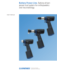
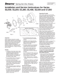
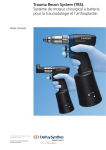
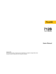
Battery Power Line. Battery-driven
power tool system for orthopaedics
and traumatology.
User’s Manual
Table of Contents
Introduction
Operating Instructions
Product Information
Indications
2
Drive Units
3
Battery
9
Universal Battery Charger II
10
Attachments for Battery Reamer/Drill
11
Universal Battery Charger II
14
Battery Pack
19
Drive Units
22
Attachments
27
Graphic Case
38
Attachment Rack
38
Care and Maintenance
40
Troubleshooting
42
Set Lists
45
Cutting Tools
48
Synthes
Indications
The Battery Power Line is a heavy-duty
battery-driven system intended for
orthopaedic and trauma applications
including drilling, sawing, inserting /
removing K-wires, DHS / DCS, and
intramedullary and acetabular reaming.
Battery reamer/drill
Drilling
Reaming
K-wire insertion
2
Battery oscillator
Battery reciprocator
Oscillating sawing
Reciprocating sawing
Synthes Battery Power Line User’s Manual
Drive Units–Technical Data
Three drive units are available for various applications:
– Battery Reamer/Drill (530.605)
– Battery Oscillator (530.610)
– Battery Reciprocator (530.615)
Environmental conditions
Operation
Transport
and Storage
Temperature
10° to 40°C
(50° to 104°F)
– 20° to 50°C
(– 4° to 122°F)
Relative humidity
10% – 100%
10% – 75%
Atmospheric
pressure
500 – 1060 hPa
500 – 1060 hPa
The machine may not be stored or operated in explosive atmospheres.
Protection systems
The Battery Power Line drive units have two protection
systems.
Thermal overload protection — switches the unit off if it
begins to overheat during operation. The unit returns to
operational status when it has cooled sufficiently. This
safety feature also ensures the unit has cooled sufficiently
following steam sterilization, before use.
Battery low-discharge protection — prevents batteries from
completely discharging, to ensure longer battery life.
Compliance
The devices comply with the following standards:
UL 60601-1 (CAN / CSA C22.2 No. 601.1)
EN 60601 (IEC 601-1)
EN 60601-1-2 (DIN EN 60601-1-2)
Synthes
3
Drive Units–Technical Data continued
Duty cycle
Intermittent operation
X min on
Y min off
Drilling and tapping
3
45
Reaming
3
45
Sawing
3
45
To prevent overheating, the handpiece and the attachment
should be allowed to cool for at least 45 minutes following
3 minutes of constant use. The user is responsible for
following the indicated guidelines. If longer periods of
constant use are required, an additional handpiece and/or
attachment should be used.
Important:
– Always use new cutting tools to prevent overheating
of the system due to reduced cutting performance.
– Careful maintenance of the system will reduce heat
development in the handpiece and the attachments.
4
Synthes Battery Power Line User’s Manual
Explanation of symbols used
The following symbols are applied to the device or individual
components.
Caution. Read the provided instructions for use
before operating the device.
Do not immerse device in liquids.
The device is classified as type BF against electrical
shock and leakage current. The device is suitable
for use on patients according to the standards
defined by UL 60601-1CAN / CSA C22.2 No. 601.1
and IEC 60601-1.
The battery contains rechargeable NiMH (nickel
metal hydride) cells. The battery is recyclable.
Batteries may not be disposed of with household
garbage. Dispose of or recycle the batteries in
accordance with local and national regulations.
The device fulfills the UL requirements for USA
and Canada.
Synthes
5
Drive Units continued
Battery Reamer/Drill (530.605)
– Speed (without attachment): 0–340 rpm
(maximum speed varies with attachment)
– Torque (without attachment): 0–15 Nm
(maximum torque varies with attachment)
– Weight (including battery pack): 1.85 kg
– Cannulation: 4.1 mm
– Protection against electric shock: BF
– Protection against water intrusion: IP X4
– Cleaning Brush (516.101) and Autoclavable Oil
(519.97) included
Attachment release ring
Facilitates one-handed removal
of attachments
Variable-speed trigger
Controls rotational speed
Release buttons
Both must be pressed
simultaneously to remove
battery casing
Battery casing
Protects sterile environment
from contamination by
unsterile battery
6
Synthes Battery Power Line User’s Manual
Mode switch
Turns drive OFF for safety during
drive unit and/or attachment
exchange, and selects clockwise
(FWD) or counterclockwise (REV)
rotation
Battery Oscillator (530.610)
– Speed: 0–12,000 oscillations per minute
– Weight (including battery pack): 2.10 kg
– Protection against electric shock: BF
– Protection against water intrusion: IP X4
– Autoclavable Oil (519.97) included
Saw head
Locking knob
Allows keyless assembly
and removal of saw blades
Collar
Allows sawing plane
to be adjusted through
360°, in 45° increments
Variable-speed trigger
Controls oscillating frequency
Release buttons
Both must be pressed
simultaneously to remove
battery casing
Battery casing
Protects sterile environment
from contamination by
unsterile battery
Mode switch
Turns drive OFF for safety during
drive unit and/or saw blade
exchange, and ON for sawing
Synthes
7
Drive Units continued
Battery Reciprocator (530.615)
– Speed: 0 – 14,000 oscillations per minute
– Weight (including battery pack): 2.00 kg
– Protection against electric shock: BF
– Protection against intrusion of water: IP X4
– Autoclavable Oil (519.97) included
Saw head
Release knob
Ejects saw blades
Collar
Allows sawing plane
to be adjusted through
360°, in 45° increments
Variable-speed trigger
Controls reciprocating frequency
Release buttons
Both must be pressed
simultaneously to remove
battery casing
Battery casing
Protects sterile environment
from contamination by
unsterile battery
Mode switch
Turns drive OFF for safety during
drive unit and/or saw blade
exchange, and ON for sawing
8
Synthes Battery Power Line User’s Manual
Battery (530.620)
–
–
–
–
–
Voltage: 14.4 VDC
Type: NiMH
Capacity: 2.0 Ah
Charging Time: 70 minutes (maximum)
Working Temperature: 0° to 50°C (32° to 122°F)
Important: Do not sterilize* batteries! Batteries will no
longer function.
* This product is validated for STERRAD® 100S sterilization system. Please, refer
to your STERRAD® equipment manufacturer’s manual for recommended STERRAD®
sterilization protocol.
Synthes
9
Specifications
Universal Battery Charger II (05.001.204)
The Universal Battery Charger II includes
four independent charging bays. Each
charging bay has three slots; the
Battery Power Line battery fits into the
first slot.
Front view
1
2
3
4
10
5
10 Battery Power Line Battery (530.620)
1
2
3
4
5
Charging bays (4)
Symbols for battery type
ON / OFF display
Control display for each charging bay
Ventilation holes
Rear view
6
7
8
9
Complies with standards:
UL 60601-1, 1st Edition
IEC 60601-1, 2nd Edition
10PB
Universal Battery Charger II
With respect to electrical shock, fire and
mechanical hazards only in accordance
with UL 60601-1/CAN/CSA C22.2
No. 601.1
6
7
8
9
Ventilation holes
Power switch
Fuses: 2 x 5 AT
Power cord connection
IEC 60601-1-2
IEC 60601-1-4
Note: Please refer to the Universal Battery Charger II User’s Manual for additional information.
10
Synthes Battery Power Line User’s Manual
Attachments for Battery Reamer/Drill (530.605)
Drilling speed attachments
All the drilling speed attachments are geared to increase
the maximum drive speed to 930 rpm while reducing the
maximum torque to 6.0 Nm.*
530.730
Chuck with key
Cannulation: 3.2 mm
Accepts round and triangular shafts
up to 7.3 mm
530.731
Chuck, keyless
Cannulation: 3.2 mm
Accepts round and triangular shafts
up to 7.3 mm
530.741
Adaptor for Radiolucent Drive
Couples Radiolucent Drive (511.30)
to the Battery Reamer/Drill (530.605)
530.750
Quick Coupling for drill bits
Cannulation: 1.2 mm
Accepts cutting tools and instruments
with AO quick coupling fitting
530.760
Large Quick Coupling
Cannulation: 3.2 mm
Accepts cutting tools and instruments
with large quick coupling fitting
* Performance specifications on file at Synthes.
Synthes
11
Attachments for Battery Reamer/Drill (530.605) continued
530.790
Quick Coupling for K-Wires
Cannulation: 4.0 mm (fully open)
To insert/remove Kirschner wires and guide
pins, 1.5 mm – 4.0 mm diameter (any length)
530.792
Hudson Drilling Attachment
Cannulation: 3.2 mm
Accepts cutting tools and instruments
with Hudson fitting
530.793
Modified Trinkle Drilling Attachment
Cannulation: 3.2 mm
Accepts cutting tools and instruments
with modified Trinkle fitting
530.794
Trinkle Drilling Attachment
Cannulation: 3.2 mm
Accepts cutting tools and instruments
with Trinkle fitting
12
Synthes Battery Power Line User’s Manual
Reaming speed attachments
All the reaming speed attachments transfer the speed and
torque of the drive unit, with a maximum speed of 340 rpm
and a maximum torque of 15.0 Nm.*
530.732
Chuck with key
Cannulation: 4.0 mm
Accepts round and triangular shafts
up to 7.3 mm
530.780
AO Reaming Attachment
Cannulation: 4.0 mm
Accepts cutting tools and instruments
with AO reaming fitting
530.782
Hudson Reaming Attachment
Cannulation: 4.0 mm
Accepts cutting tools and instruments
with Hudson fitting
530.783
Modified Trinkle Reaming Attachment
Cannulation: 4.0 mm
Accepts cutting tools and instruments
with modified Trinkle fitting
530.784
Trinkle Reaming Attachment
Cannulation: 4.0 mm
Accepts cutting tools and instruments
with Trinkle fitting
530.795
Large Modified Trinkle Reaming Attachment
Cannulation: 4.0 mm
Accepts cutting tools and instruments
with a large tapered modified Trinkle fitting
* Performance specifications on file at Synthes.
Synthes
13
Operating Instructions — Universal Battery Charger II (05.001.204)
Connect the electrical cord to the charger, and plug the cord
into a grounded 110 / 120 VAC outlet.
Turn on the charger by pressing the “I” on the power switch
(Figure 1).
The ON / OFF display light on the front of the charger will
illuminate (Figure 2).*
Note: If the red caution display light for a single charging
bay illuminates before the battery is inserted, this charging
bay is damaged (Figure 3). The batteries can still be charged
in the other charging bays, but it is recommended that the
device be sent to the Synthes Service Department for repair.
Important: Do not operate the charger in the direct vicinity
of radiators or other heat emitting devices, as these can
affect the device.
Figure 1
Place the charger on a hard, non-slip, stable base. Ensure
that the ventilation holes in the base of the device are not
covered by towels or other objects.
Do not expose the device to direct sunlight or moisture.
Do not cover the side ventilation holes on the device.
Figure 2
Figure 3
*If LEDs do not follow this sequence, refer to the troubleshooting section, page 45.
14
Synthes Battery Power Line User’s Manual
Insert the battery into one of the appropriate charging bays.
The yellow LED should remain illuminated, indicating that
the battery is charging (Figure 4).*
When the green LED illuminates, the battery is fully charged
(Figure 5).*
Note: Batteries can be removed during the charging process;
however, they may not be fully charged and operational time
may be shorter.
Important: Always leave the charger switched on when a
battery is inserted in a charging bay.
Figure 4
Figure 5
*If LEDs do not follow this sequence, refer to the troubleshooting section, page 45.
Synthes
15
Operating Instructions–Universal Battery Charger II continued
Temperature monitoring
The battery and the charger heat up during the charging
process. Therefore, the ventilation holes should not be covered.
flashing
If the temperature is too high, the yellow battery symbol
will flash (Figure 1). To protect the battery, the device stops
charging until the battery has cooled down. If this occurs,
do not remove the battery from the charger until the yellow
battery symbol stays illuminated. The charging time will be
longer in this case.
Charging new batteries or batteries not recently used
New Battery Power Line batteries that have not been used
for longer than 6 weeks and that have not been stored in an
activated charger may require 3 to 5 charging cycles to reach
their full capacity. When in doubt, the charger can be used
to check the battery status and to refresh the battery (see
page 17).
Figure 1
Errors during charging
The following errors may occur when charging a battery:
Yellow display light flashes (Figure 1):
The battery is too hot and must cool down before the
charging process can automatically resume. The battery
can be left in the charger.
Red display light illuminates (Figure 2):
The battery is damaged and must be replaced.
No display light:
The battery has not engaged in the charging bay or has
not been recognized by the device. Remove the battery
and insert again or use another charging bay.
16
Synthes Battery Power Line User’s Manual
Figure 2
Diagnostic test
Battery Power Line batteries can be tested for remaining
capacity or, if they have not been used for some time, can
be refreshed with the Universal Battery Charger II.
The following can affect battery performance:
– new, unused battery
– battery not used for long period
of time
– old battery
Important: The diagnostic test takes up to 10 hours and
should only be carried out if there is enough time to do so.
After the battery is inserted, the yellow battery symbol
illuminates. To refresh and check the battery, press the
button with the exclamation mark on the charger display
of the charging bay for at least 2 seconds (Figure 1) until
the yellow arrow illuminates (Figure 2). The device then
carries out the diagnostic test. The yellow arrow remains
illuminated throughout the diagnostic process.
Figure 1
Figure 2
Synthes
17
Operating Instructions–Universal Battery Charger II continued
Diagnostic test continued
Diagnosis
Green battery symbol illuminates (Figure 3): Battery has been
tested, charged and is ready to use. Battery Power Line
battery is charged with at least 70% capacity remaining.
Red caution symbol illuminates (Figure 4): Battery has been
checked, is not charged and cannot be used. The battery
must be replaced.
Important: The diagnostic test takes up to 10 hours and
should only be carried out if there is enough time to do so.
Note: Batteries can be charged or undergo diagnostic tests
independently in each charging bay.
Important:
– To recharge batteries normally, do not press the exclamation
mark button.
– Checking the battery status and refreshing the battery have
an impact on the battery. If this is carried out frequently,
the lifespan of the battery may be affected.
– Do not remove the battery from the charging bay while
the yellow display is illuminated. Wait until the diagnostic
process has ended and the green or red display illuminates.
Only then is the battery status clearly assessed.
– If the diagnostic process is interrupted, such as a power
outage or a switch to the hospital’s emergency power
system, the diagnostic process must be restarted.
18
Synthes Battery Power Line User’s Manual
Figure 3
Figure 4
Operating Instructions — Battery Pack
Synthes nonsterile batteries and advanced charging technology
optimize intraoperative battery capacity, maximize battery
lifespan, significantly decrease memory effect, and shorten
turnaround time. One universal battery charger for all Synthes
battery-driven systems simplifies the charging process. Simple
aseptic technique preserves the sterile field when assembling
the battery pack.
1
530.680
OR
530.681
Instruments
530.620
Battery
530.650
Battery Insertion Shield
530.680
Battery Casing
530.681
Battery Casing with Lock
Scrubbed person
1. Ensure the lid of the battery casing is fully open.
2. Position the battery insertion shield securely on top of the
battery casing. The battery insertion shield helps guide the
battery into the battery casing and prevents contamination
of the sterile casing by the nonsterile battery.
Scrubbed
person
2
530.650
530.680
OR
530.681
Scrubbed
person
Synthes
19
Operating Instructions — Battery Pack continued
Circulating person
3. Insert the battery into the battery casing (3a) and press
down to ensure it is seated fully (3b).
4. Remove the battery insertion shield.
3a
Circulating
person
Scrubbed
person
3b
Circulating
person
Scrubbed
person
4
Scrubbed
person
20
Synthes Battery Power Line User’s Manual
Circulating
person
Scrubbed person
5. Close the lid of the battery casing, taking care to not
contact the battery. To lock the battery casing, press down
with the palm of the hand and then turn the latch while
maintaining pressure on the lid.
5
Note: One battery is usually sufficient for one operation;
however, preparing additional battery packs for each drive
unit prevents the need for intraoperative exchange of battery
packs between drive units. It also allows rapid intraoperative
battery pack exchange if required.
Scrubbed
person
6. Insert the battery pack into the drive unit, ensuring the
contacts on the battery pack align with the contacts in the
recess of the drive unit (as shown). Press firmly to ensure
the battery pack is engaged correctly, and check by pulling
lightly downward on the battery pack. (For safety, the
battery pack can be inserted fully only when in the
correct orientation).
6
Important:
To prevent injuries, the mode switch of the drive unit should
always be in the “OFF” position when inserting or removing
the battery pack.
Installing the battery pack just before use prevents unwanted
discharge of battery capacity.
Scrubbed
person
7
7. Press both release buttons simultaneously on the drive unit
to remove the battery pack.
Important: Do not sterilize batteries! Batteries will no
longer function.
Scrubbed
person
Synthes
21
Operating Instructions — Drive Units
Battery Oscillator (530.610)
To operate the drive unit, turn the mode switch to the
“ON” position.
The single variable-speed trigger allows control of the oscillating frequency from 0 to 12,000 oscillations per minute.
Ensure the drive unit is running prior to contacting the bone.
Optimal sawing performance is achieved by gently moving
back and forth in the plane of the saw blade, so the blade
can oscillate freely slightly beyond the bone.
Important: To prevent injuries, the mode switch of the drive
unit should always be in the “OFF” position when inserting
or removing saw blades, or adjusting the sawing plane.
To operate, turn the mode switch to the “ON” position.
22
Synthes Battery Power Line User’s Manual
Insert saw blade
– Ensure the saw blade coupling is fully open by turning
the locking knob in the direction of the arrow.
– Insert an oscillating saw blade into the coupling and
align the blade in the desired direction (variable in
45° increments).
– Turn the locking knob in the opposite direction
to the arrow to secure the blade.
Adjust sawing plane
– Pull the collar back and rotate the saw head to adjust
the sawing plane (variable in 45° increments).
– Release the collar and turn the saw head slightly until
it locks in place.
Remove saw blade
Open the saw blade coupling fully by twisting the locking
knob in the direction of the arrow and remove the oscillating
saw blade.
Synthes
23
Operating Instructions — Drive Units
continued
Battery Reciprocator (530.615)
To operate the drive unit, turn the mode switch to the
“ON” position.
The single variable-speed trigger allows control of the reciprocating frequency from 0 to 14,000 oscillations per minute.
Ensure the drive unit is running prior to contacting the bone.
Optimal sawing performance is achieved by gently moving
back and forth in the plane of the saw blade, so the blade
can reciprocate freely slightly beyond the bone.
Important: To prevent injuries, the mode switch of the drive
unit should always be in the “OFF” position when inserting
or removing saw blades, or adjusting the sawing plane.
To operate, turn the mode switch to the “ON” position.
24
Synthes Battery Power Line User’s Manual
Insert saw blade
Insert a reciprocating saw blade into the coupling and push
until the saw blade locks in place. (If the blade cannot be
inserted, turn the release knob in the direction of the arrow
to open the coupling).
Adjust sawing plane
– Pull the collar back and rotate the saw head to adjust
the sawing plane (variable in 45° increments).
– Release the collar and turn the saw head slightly until
it locks in place.
Remove saw blade
Turn the release knob in the direction of the arrow to eject
the reciprocating saw blade.
Synthes
25
Operating Instructions — Drive Units
continued
Battery Reamer/Drill (530.605)
For clockwise rotation, turn the mode
switch to the “FWD” position.
For counterclockwise rotation, turn
the mode switch to the “REV” position.
Mode switch
The single variable-speed trigger allows
control of the speed from 0 to maximum rpm. Maximum torque and speed
vary, depending on the attachment
(see pages 11–13).
For clockwise rotation,
turn the mode switch
to the “FWD” position.
26
Synthes Battery Power Line User’s Manual
For safety, turn the
mode switch to the
“OFF” position.
For counterclockwise
rotation, turn the mode
switch to the “REV”
position.
Operating Instructions — Attachments
Battery Reamer/Drill attachments
Instrument
530.605
Battery Reamer/Drill
Important: To prevent injuries, the mode switch of the drive
unit should always be in the “OFF” position when inserting
or removing attachments and instruments.
Insert attachment
– Insert the attachment into the coupling of the battery
reamer/drill, aligning the positioning pins of the attachment
with the grooves on the release ring.
– Push and turn the attachment clockwise until it locks
in place.
Remove attachment
Turn the attachment release ring in the direction of the
arrow and remove the attachment.
Synthes
27
Operating Instructions — Attachments continued
Drilling speed attachments
All the drilling speed attachments are geared to increase the
maximum drive unit speed to 930 rpm while reducing the
maximum torque to 6.0 Nm.*
Chuck with key (530.730)
Accepts round and triangular shafts up to 7.3 mm.
Insert an instrument
– Open the chuck jaws by turning the key counterclockwise,
or by manually turning the collar.
– Insert the instrument shaft into the opened chuck.
– Close the chuck manually by rotating the collar, keeping
the shaft centered in the jaws.
– Tighten the chuck by turning the key clockwise.
Remove an instrument
– Turn the key counterclockwise to open the jaws.
– Remove the instrument.
* Performance specifications on file at Synthes.
28
Synthes Battery Power Line User’s Manual
Collar
Chuck, keyless (530.731)
Accepts round and triangular shafts up to 7.3 mm.
Insert an instrument
– Open the chuck jaws by holding on to the retaining
ring and manually turning the chuck clockwise.
– Insert the instrument shaft into the opened chuck.
– Close the chuck by holding on to the retaining ring
and manually turning the chuck counterclockwise.
– Ensure the instrument shaft is centered in the chuck.
Remove an instrument
– Open the chuck jaws by holding on to the retaining
ring and manually turning the chuck clockwise.
– Remove the instrument.
Clockwise
Chuck
Retaining
ring
Synthes
29
Operating Instructions — Attachments continued
Drilling speed attachments continued
Adaptor for Radiolucent Drive (530.741)
Instruments
511.30
Radiolucent Drive
530.605
Battery Reamer/Drill
530.741
Adaptor for Radiolucent Drive
Adaptor allows the radiolucent drive to be used with the
battery reamer/drill.
Assemble radiolucent drive
– After inserting the adaptor for radiolucent drive into the
battery reamer/drill, slide the radiolucent drive over the
attachment and twist until the drive shaft engages.
Remove radiolucent drive
– To remove, pull the radiolucent drive off the attachment.
511.30
530.741
530.605
30
Synthes Battery Power Line User’s Manual
Quick Coupling for drill bits (530.750)
Accepts cutting tools and instruments with an AO quick
coupling fitting.
Insert an instrument
– Introduce the instrument into the attachment, then
push and turn the instrument until it locks in place.
– Pull lightly on the instrument to ensure it is secure.
Note: It is not necessary to pull back the collar of the
attachment to insert the instrument.
Remove an instrument
– Pull back the collar of the attachment and remove
the instrument.
Synthes
31
Operating Instructions — Attachments continued
Drilling speed attachments continued
Large Quick Coupling (530.760)
Accepts cutting tools and instruments with a large quick
coupling fitting. These include DHS/DCS triple reamers, large
quick coupling screwdriver shafts, large quick coupling cannulated drill bits for Synthes intramedullary nailing systems
and the Synthes Reamer/Irrigator/Aspirator (RIA) system.
Insert an instrument
– Push forward on the collar of the attachment and insert
the instrument, turning it slightly to align the keyway.
– Release the collar, pulling lightly on the instrument to
ensure it is secure.
Remove an instrument
– Push forward on the collar of the attachment and
remove the instrument.
32
Synthes Battery Power Line User’s Manual
Quick Coupling for K-Wires (530.790)
Allows insertion and removal of Kirschner wires and guide
pins with diameters from 1.5 mm to 4.0 mm, in any length.
Insert a K-wire/guide pin into the attachment
– Set the appropriate diameter range on the attachment.
– Insert the wire/pin into the front of the attachment. The
attachment is spring-loaded to prevent the wire/pin from
falling out.
Insert a K-wire/guide pin into the bone
– Pull the attachment lever toward the drive unit to grip
the wire/pin and press the trigger to insert.
– Release the lever to reposition the attachment on the
wire/ pin, if required.
Remove a K-wire/guide pin from the bone
– Set the appropriate diameter range on the attachment.
– Slide the attachment over the wire/pin. Set the mode
switch on the drive unit to “REV” (reverse).
– Pull the attachment lever toward the drive unit to grip
the wire/pin. Press the trigger while pulling backward
to remove.
Synthes
33
Operating Instructions — Attachments continued
Drilling speed attachments continued
Hudson Drilling Attachment (530.792)
Accepts cutting tools and instruments with a Hudson fitting.
Modified Trinkle Drilling Attachment (530.793)
Accepts cutting tools and instruments with a modified
Trinkle fitting.
Trinkle Drilling Attachment (530.794)
Accepts cutting tools and instruments with a Trinkle fitting.
Insert an instrument
– Pull back the collar of the attachment and insert the
instrument, turning it slightly to align the keyway.
– Release the collar, pulling lightly on the instrument
to ensure it is secure.
Remove an instrument
– Pull back the collar of the attachment and remove
the instrument.
34
Synthes Battery Power Line User’s Manual
Reaming speed attachments
All the reaming speed attachments transfer the speed
and torque of the drive unit, with a maximum speed
of 340 rpm and a maximum torque of 15.0 Nm.*
Chuck with key (530.732)
Accepts round and triangular shafts up to 7.3 mm.
Insert an instrument
– Open the chuck jaws by turning the key counterclockwise,
or by manually turning the collar.
– Insert the instrument shaft into the opened chuck.
– Close the chuck manually by rotating the collar, keeping
the shaft centered in the jaws.
– Tighten the chuck by turning the key clockwise.
Remove an instrument
– Turn the key counterclockwise to open the jaws.
– Remove the instrument.
* Performance specifications on file at Synthes.
Synthes
35
Operating Instructions — Attachments continued
Reaming speed attachments continued
AO Reaming Attachment (530.780)
Accepts cutting tools and instruments with an AO reaming
fitting including intramedullary reaming shafts with the
AO reaming fitting.
Insert an instrument
– Insert the instrument into the attachment and turn
it clockwise until it locks in place.
– Pull lightly on the instrument to ensure it is secure.
Note: It is not necessary to pull back the collar of the
attachment to insert the instrument.
Remove an instrument
– Pull back the collar of the attachment and remove
the instrument.
36
Synthes Battery Power Line User’s Manual
Hudson Reaming Attachment (530.782)
Accepts cutting tools and instruments with a Hudson fitting.
Modified Trinkle Reaming Attachment (530.783)
Accepts cutting tools and instruments with a modified
Trinkle fitting.
Trinkle Reaming Attachment (530.784)
Accepts cutting tools and instruments with a Trinkle fitting.
Large Modified Trinkle Reaming Attachment (530.795)
Accepts cutting tools and instruments with a large, tapered,
modified Trinkle fitting.
Insert an instrument
– Pull back the collar of the attachment and insert the
instrument, turning it slightly to align the keyway.
– Release the collar, pulling lightly on the instrument
to ensure it is secure.
Remove an instrument
– Pull back the collar of the attachment and remove
the instrument.
Synthes
37
Operating Instructions — Graphic Case (690.570)
and Attachment Rack (690.572)
The graphic case provides organized storage and serves as
a sterilization container for the system.
The attachment rack provides organized storage and serves
as a sterilization container for the attachments. It is also a
stand for the drive units in the sterile field.
Grommets (690.574.04) provided with the attachment rack
are designed to help OR personnel organize the attachments
in the rack by plugging the holes for attachments they did
not purchase. The grommets are autoclavable, allowing them
to be left in the attachment rack for cleaning and sterilization.
Graphic Case, for Battery Power Line Set includes: Lid (690.571),
Attachment Rack (690.572) and Insert Tray (690.573)
Use of the attachment rack in the sterile field
Up to three drive units with battery packs assembled can
be holstered in the recesses of the lid. The attachment rack
can be used to support the drive units, for assembling/
disassembling attachments, and for inserting/removing
cutting tools.
38
Synthes Battery Power Line User’s Manual
Open the attachment rack
Lift the attachment rack out of the graphic case and stand
it in the sterile field. Pull the handles up, fold the handles
out, open the lid and push the handles down.
Pull handles up
Fold handles out
Open lid, push handles down
Close the attachment rack
Pull the handles up, fold the handles out, close the lid
and fold the handles in. Return the attachment rack to
the graphic case and push the handles down.
Pull handles up and fold out.
Close lid.
Fold handles in to secure the lid
Closed, handles down
Synthes
39
Care and Maintenance
Regular care and maintenance according to the following
guidelines can significantly increase the reliability and
lifespan of the system. Synthes recommends annual
preventive services. Yearly maintenance will ensure that the
equipment maintains the highest standard of performance
and will prolong the life of the system.
Important: Disassemble battery pack and return batteries
to charger immediately after each use. Do not disinfect,
immerse, or sterilize batteries. Batteries may be wiped
with a cloth.
– Before cleaning and sterilization, remove attachments,
instruments and cutting tools from the drive units.
– Cleaning and lubrication should be performed immediately
after each use.
– Clean the drive units, attachments and battery casings by
hand. Never immerse or clean in an automatic washer
or ultrasonic cleaner.
– Use a neutral pH cleaning solution.
Caution: Do not sterilize* batteries! Batteries will no
longer function.
Cleaning batteries and Universal Battery Charger II
To clean batteries and charger, wipe with a soft cloth using
a neutral enzymatic or neutral detergent solution.
Important: Do not use solvents to disinfect the batteries.
Battery poles must not contact water or solvents: Danger
of short circuiting!
* This product is validated for STERRAD® 100S sterilization system. Please, refer
to your STERRAD® equipment manufacturer’s manual for recommended STERRAD®
sterilization protocol.
40
Synthes Battery Power Line User’s Manual
Battery storage and charging
After cleaning, insert the batteries into the charger.
The charger continuously monitors the battery level and
automatically recharges as required. This ensures the
batteries are fully charged and ready for use at any time.
When all four charging bays are occupied, additional
batteries can be stored in a cool dry place. Before the
next use, the batteries must be fully charged.
Important:
New batteries, and batteries stored out of the charger for
a prolonged period of time, may require two or three
charging cycles to achieve full capacity.
Always leave the charger switched on when a battery is
inserted in a charging bay to ensure batteries are fully
charged and to prevent discharge.
For care and maintenance of Battery Power Line Equipment please refer to
“Manual Cleaning Instructions” chart (J9662) and “Lubrication Chart” (J9663)
for Synthes battery-driven power equipment and the “Sterilization Guide for
Battery Power Line Sets” (J5701).
Synthes
41
Troubleshooting — Drive Units and Attachments
Problem
Possible Causes
Remedy
Mode switch OFF.
Set mode switch to ON/FWD/REV.
Drive unit has not cooled after
sterilization.
Allow to cool to room temperature.
No electrical contact between
drive unit and casing.
Reinsert or change battery casing.
Battery is drained.
Charge or replace battery.
Drive unit lacks power.
Battery is drained.
Charge or replace battery.
Drive unit suddenly stops.
Battery is drained.
Charge or replace battery.
Drive unit has overheated.
Allow to cool to room temperature.
Drive unit continues to run after
releasing trigger.
Trigger is jammed by residue.
Immediately turn mode switch to OFF.
Operate trigger repeatedly and follow
care and maintenance guidelines.*
Attachments will not couple to battery
reamer/drill.
Coupling is blocked by residue.
Turn mode switch to OFF.
Remove solid particles with pickups
and follow care and maintenance
guidelines.*
Instruments are difficult or impossible
to attach.
Attachment or instrument worn
excessively.
Replace attachment or instrument.
Battery oscillator vibrates excessively.
Saw blade coupling is loose.
Retighten locking knob.
Saw blade is inserted incorrectly.
Reposition saw blade and tighten
locking knob.
Drive unit does not start.
* For additional information, please refer to the Manual Cleaning Instructions (J9662) and Lubrication
Chart (J9663) for Synthes battery-driven power equipment.
42
Synthes Battery Power Line User’s Manual
Troubleshooting — Universal Battery Charger II
Problem
Possible Causes
Remedy
ON / OFF display does not illuminate.
Charger is switched off.
Turn charger power switch on.
Power cord is not plugged in.
Connect power cord to charger,
plug into wall outlet, and switch on.
Power supply is interrupted
(e.g., damaged fuse).
Check power supply. Replace fuse if
necessary.
Charger is damaged.
Send to Synthes Service Department.
ON / OFF display flashes.
Charger is damaged.
Send to Synthes Service Department.
Battery is inserted
and charge display status does
not illuminate.
Battery is not fully inserted.
Ensure the battery is inserted properly.
Contacts in the charging bay are dirty.
Carefully clean contacts with soft brush.
Battery was not recognized by
the charger.
Remove battery and reinsert in an
open charging bay.
Battery is damaged.
Replace battery.
Charging bay is damaged.
Send to Synthes Service Department.
Charging bay is damaged.
Send to Synthes Service Department.
Battery is too hot.
Leave battery inserted in charging bay.
Charger automatically restarts the
charging process once the battery
has cooled.
Red caution display
illuminates when no battery
is inserted.
Yellow battery display
when charging.
flashes
Please refer to the Universal Battery Charger II User’s Manual for additional information.
Synthes
43
Troubleshooting — Universal Battery Charger II continued
Problem
Possible Causes
Remedy
Arrow display does not
illuminate when exclamation
button is pressed.
Button was released too soon.
Press button and hold for at least
2 seconds.
Charging bay is damaged.
Send to Synthes Service Department.
Charger has an error.
Switch off charger, wait 3 seconds,
and switch charger on. If the ON/OFF
display flashes, send to Synthes Service
Department.
Battery is being inserted
into wrong slot in charging bay.
Insert battery into correct slot in
charging bay.
Contacts in charging bay are bent.
Send to Synthes Service Department.
Battery is impossible to insert.
Charger is noisy.
Battery performance is low.
Vents on sides, back or base are covered. Position charger so that vents are
exposed.
Charger positioned next to heat source.
Position charger away from heat source.
Insufficient battery status.
Refresh battery (see page 17).
Expected battery life is reached.
Test battery (see pages 17 and 18). If the
red display illuminates, replace battery.
Battery is not ready for use.
Charge battery until green display
illuminates.
Drive unit or attachment is compromised.
(i.e., due to insufficient maintenance)
Send drive unit to Synthes Service
Department for repair.
If the suggested solutions are unsuccessful, please contact
the Synthes Service Department at 1 (800) 288-6698.
Synthes recommends an annual preventive maintenance
service by qualified Synthes personnel.
44
Synthes Battery Power Line User’s Manual
Battery Power Line Set (150.119)
Graphic Case
690.570
Graphic Case, for Battery Power Line Set
Includes: Lid (690.571), Attachment Rack
(690.572) and Insert Tray (690.573)
Instruments
05.001.204
Universal Synthes Battery Charger II
530.605
Battery Reamer/Drill
530.610
Battery Oscillator
530.615
Battery Reciprocator
530.620
Battery, 3 ea.
530.650
Battery Insertion Shield, 3 ea.
530.680
Battery Casing, 3 ea.
530.730
Chuck with key
530.731
Chuck, keyless
530.741
Adaptor for Radiolucent Drive
530.750
Quick Coupling for drill bits
530.760
Large Quick Coupling
530.780
AO Reaming Attachment
530.782
Hudson Reaming Attachment
530.783
Modified Trinkle Reaming Attachment
530.784
Trinkle Reaming Attachment
530.790
Quick Coupling for K-Wires
530.792
Hudson Drilling Attachment
530.793
Modified Trinkle Drilling Attachment
530.794
Trinkle Drilling Attachment
150.119
690.573
690.572
Note: For additional information, please refer to package insert.
Synthes
45
Battery Power Line Sets
Trauma (150.119TR) and Joint Replacement (150.119JR)
Battery Power Line Set — Trauma (150.119TR)
690.570
Graphic Case, for Battery Power Line Set
Includes: Lid (690.571), Attachment Rack
(690.572) and Insert Tray (690.573)
05.001.204
Universal Synthes Battery Charger II
530.605
Battery Reamer/Drill
530.610
Battery Oscillator
530.620
Battery, 2 ea.
530.650
Battery Insertion Shield, 2 ea.
530.680
Battery Casing, 2 ea.
530.730
Chuck with key
530.741
Adaptor for Radiolucent Drive
530.750
Quick Coupling for drill bits
530.760
Large Quick Coupling
530.780
AO Reaming Attachment
530.790
Quick Coupling for K-Wires
Battery Power Line Set — Joint Replacement
(150.119JR)
690.570
Graphic Case, for Battery Power Line Set
Includes: Lid (690.571), Attachment Rack
(690.572) and Insert Tray (690.573)
05.001.204
Universal Synthes Battery Charger II
530.605
Battery Reamer/Drill
530.610
Battery Oscillator
530.615
Battery Reciprocator
530.620
Battery, 3 ea.
530.650
Battery Insertion Shield, 3 ea.
530.680
Battery Casing, 3 ea.
530.730
Chuck with key
530.782
Hudson Reaming Attachment
530.783
Modified Trinkle Reaming Attachment
530.792
Hudson Drilling Attachment
530.793
Modified Trinkle Drilling Attachment
46
Synthes Battery Power Line User’s Manual
05.001.204
Also Available
Battery Power Line Components and Accessories
05.001.140
Medical Grade Power Cord
510.19
Replacement Key, for 4.5 mm Chuck
511.30
Radiolucent Drive
516.101
Cleaning Brush
519.97
Autoclavable Oil
530.681
Battery Casing with Lock, for Battery
Power Line
530.732
Chuck with key, reaming speed
530.795
Large Modified Trinkle Reaming Attachment
690.574.04
Grommets (4/pkg.)
690.575
Graphic Case for Battery Power Line
Reciprocator
Service and Extended Warranty Programs
W1.150.119 One-Year Extended Warranty Program
for Battery Power Line Set
W3.150.119 Three-Year Extended Warranty Program
for Battery Power Line Set
690.575
530.681
Synthes
47
Cutting Tools
Sagittal Saw Blades for Battery Oscillator (530.610)
Saw blades with aggressive tooth, calibrated, sterile*
for arthroplasty
Blade
Calibrated
Cutting
Width (mm) Length (mm) Thickness (mm)
05.003.100S
12.5
90
0.89
05.003.102S
12.5
90
1.00
05.003.103S
12.5
90
1.07
05.003.104S
12.5
90
1.19
05.003.106S
12.5
90
1.27
05.003.107S
12.5
90
1.37
05.003.109S
12.5
90
1.47
05.003.110S
05.003.112S
05.003.113S
05.003.114S
05.003.116S
05.003.117S
05.003.119S
19
19
19
19
19
19
19
90
90
90
90
90
90
90
0.89
1.00
1.07
1.19
1.27
1.37
1.47
05.003.120S
05.003.122S
05.003.123S
05.003.124S
05.003.126S
05.003.127S
05.003.129S
19-12.5**
19-12.5**
19-12.5**
19-12.5**
19-12.5**
19-12.5**
19-12.5**
90
90
90
90
90
90
90
0.89
1.00
1.07
1.19
1.27
1.37
1.47
05.003.130S
05.003.132S
05.003.133S
05.003.134S
05.003.136S
05.003.137S
05.003.139S
25
25
25
25
25
25
25
90
90
90
90
90
90
90
0.89
1.00
1.07
1.19
1.27
1.37
1.47
* Please contact your Synthes Sales Consultant or Customer Service
for additional information.
** Blade width-shaft width
Illustrations not to scale.
48
Synthes Battery Power Line User’s Manual
05.003.100S
05.003.116S
05.003.126S
05.003.136S
Sagittal Saw Blades for Battery Oscillator
(530.610) continued
Saw blades, calibrated, sterile*
Blade
Width (mm)
519.100S
27
519.103S
10
519.104S
10
519.105S
20
519.106S
19
519.113S
18
519.150S
14
519.170S
27
519.190S
50
519.200S
27
519.210S
27
519.230S
6
519.250S
14
Calibrated
Length (mm)
50
25
50
50
70
70
50
70
70
70
70
25
25
Cutting
Thickness (mm)
0.6
0.6
0.6
0.6
1.0
1.2
0.6
0.8
0.8
1.0
1.2
0.6
0.6
519.106S
519.170S
* Please contact your Synthes Sales Consultant or Customer Service
for additional information.
Illustrations not to scale.
Synthes
49
Cutting Tools continued
Reciprocating Saw Blades for Reciprocating Saw
Attachment (05.001.225)
Saw blades, sterile*
Blade
Cutting
Cutting
Height (mm) Length (mm) Thickness (mm)
511.905S
10
80
1.05
511.906S
10
70
1.27
511.907S
10
55
1.05
511.909S
10
55
0.85
511.912S
12
68
1.10
(double-sided)
511.913S
12
68
1.00
(double-sided)
511.914S
12
68
0.80
(double-sided)
511.915S†
10
40
1.10
Drill Bits, Three-Fluted, Brad Point*, for Radiolucent
Drive (511.30)
Diameter
Length
(mm)
(mm)
511.411
511.412
511.413
511.414
511.415
511.416
511.417
511.418
511.431
511.432
2.0
2.5
2.7
3.2
3.5
3.6
4.0
4.5
3.2
4.0
* Please contact your Synthes Sales Consultant or Customer Service
for additional information.
Use with Sternum Top for Reciprocating Saw Attachment (511.904).
50
Synthes Battery Power Line
511.909S
511.912S
511.417
150
150
150
150
150
150
150
150
105
105
Drill Bits, Three-Fluted, Needle Point*, for Radiolucent
Drive (511.30)
Diameter
Length
(mm)
(mm)
03.010.100
3.2
145
03.010.101
4.2
145
03.010.102
5.0
145
†
511.905S
03.010.100
Synthes Anspach
4500 Riverside Drive
Palm Beach Gardens, FL 33410
Telephone: (561) 627-1080
To order: (800) 327-6887
Fax: (800) 327-6661
E-mail: [email protected]
© 2004 Synthes, Inc. or its affiliates. All rights reserved.
Synthes (Canada) Ltd.
2566 Meadowpine Boulevard
Mississauga, Ontario L5N 6P9
Telephone: (905) 567-0440
To order: (800) 668-1119
Fax: (905) 567-3185
STERRAD is a trademark of Advanced Sterilization Products.
DCS, DHS and Synthes are trademarks of Synthes, Inc. or its affiliates.
www.synthes.com
www.anspach.com
Printed in U.S.A. 12/11 J5559-E