1
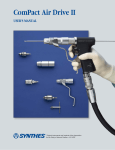
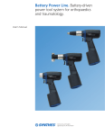
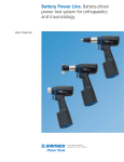
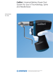
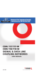
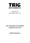
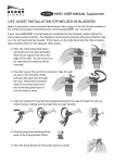
Power Drive. Battery-driven
power tool system for orthopaedics
and traumatology.
User’s Manual
Table of Contents
Introduction
Operating Instructions
Product Information
Power Drive
2
Battery and Charger
3
Attachments for Power Drive
4
Universal Battery Charger
6
Battery Pack
7
Drive Unit
9
Attachments
10
Care and Maintenance
16
Sterilization
21
Troubleshooting
22
Set List
24
Synthes
Power Drive (530.100)
–
–
–
–
Variable speed: 0 – 750 rpm
Weight, including battery: 1,750 g
Torque: 4.5 Nm
Cannulation: 3.2 mm diameter
Attachment release ring
Allows easy exchange
of attachments
Attachment coupling
Accepts a wide variety
of attachments
Instant-reverse trigger
Reverses rotation to
counterclockwise direction
Variable-speed trigger
Controls rotational speed
Battery casing
Simple twist-off design allows
easy intraoperative battery
exchange. Holds battery in
sterile environment
This device complies with the following standards:
UL 2601-1
EN 60601 (IEC 601-1)
EN 60601-1-1 (VDE 0750 part 1 and 2)
EN 55011 (VDE 0875 part 11)
Limiting values of class B, group 1
2
Synthes Power Drive
Safety lock
Turns drive
off for safe
attachment
exchange
Battery and Charger
Battery (530.200)
– Voltage: 12 VDC
– Capacity: 1.0 Ah
– Type: NiCd
– Charging time: 80 minutes maximum
– Working temperature range: 0° to 50° C (32° to 122° F)
– Discharge protection: Prevents total battery discharge,
eliminating memory effect, maintaining battery capacity,
and increasing battery life
Important: Do not sterilize batteries! Batteries will no longer
function.
Universal Battery Charger (530.601)
– Four charging bays accept Small Battery Drive,
Power Drive and Battery Power Line batteries
– One (1) battery can be placed in each charging
bay allowing a maximum of four (4) batteries
to be charged at the same time
Status
indicator
panels
Power switch
Fuse: 2 x 5 AT 250 V
(SPT 5 x 20 mm)
Socket for power cord
Complies with standards:
UL 60950
IEC 60950
EN 55022 class B
EN 61000-3-2, 3
EN 61000-4-2, 3, 4, 5, 6, 11
Synthes
3
Attachments for Power Drive
511.731
Jacobs Chuck, Keyless
– Accepts K-wires and Steinmann pins with
round shafts from 1.0 mm to 6.0 mm in
diameter or triangular shafts up to 6.5 mm
511.75
Quick Coupling, for drill bits
– Accepts quick coupling drill bits
– Allows use of Oscillating Drill Attachment
(511.20) and Radiolucent Drive (511.30)
511.761
Large Quick Coupling
– Accepts DHS and DCS triple reamers and
large quick coupling cannulated drill bits
511.785
Reduction Drive Unit
– Allows direct medullary reaming with
flexible shafts
– Reduces maximum speed to 270 rpm
– Increases maximum output torque to 12.5 Nm
– Automatically locks reverse trigger to
prevent damage to wound reaming shafts
– Accepts reaming rods up to 3.2 mm
in diameter
511.786
Reduction Drive Unit with Reverse
– Allows direct medullary reaming with
flexible shafts
– Reduces maximum speed to 270 rpm
– Increases maximum output torque to 12.5 Nm
– Accepts reaming rods up to 3.2 mm
in diameter
4
Synthes Power Drive
511.791
Quick Coupling for K-Wires
– For insertion of K-wires from 0.6 mm
to 3.2 mm in diameter
– Allows use of any length K-wire
511.801
Oscillating Saw Attachment II
– Keyless quick coupling for saw blades
allows quick intraoperative blade exchange
– Saw blade oscillates 4.5° for optimal
cutting performance
– Accepts standard or aggressive tooth
saw blades
Synthes
5
Operating Instructions — Universal Battery Charger (530.601)
Connect the charger to the electrical cord, and plug the
cord into a 110/120 VAC outlet.
Turn on the charger by pressing the power switch to ON.
All LEDs on the status indicator panels will illuminate
(red, yellow and green) when the charger is empty and
ready to charge (Figure 1).
Insert the battery into one of the appropriate charging bays.
Only the yellow LED should remain illuminated, indicating
that the battery is charging (Figure 2).
When the green LED illuminates, the battery is fully charged
and operational (Figure 3). The battery should be left in the
charging bay until needed.
Figure 1
The battery can be removed during the charging process;
however, the battery may not be fully charged and operational duration may be shorter.
Important:
Always leave the charger switched on when a battery is
inserted in a charging bay. Leaving a battery in the charger
when it is switched off or unplugged may permanently
discharge the battery.
Never attempt to insert more than one battery in the same
charging bay.
Figure 2
Note: If LEDs do not follow this sequence, refer to the
troubleshooting section, page 23.
Figure 3
6
Synthes Power Drive
Operating Instructions — Battery Pack
Assemble battery pack
1
2
Instruments
530.250
Battery Insertion Shield
530.280
Battery Casing
Inserting the battery into the casing
and preserving the sterile field requires
one scrubbed nurse/operating room
technician and one circulating nurse.
Scrubbed person
1 Hold the sterilized battery casing.
Open the lid by depressing the
silver switch and rotating the latch
counterclockwise.
2 Place the sterilized battery insertion
shield on the battery casing. The
insertion shield helps guide the
battery into the case, ensuring that
the nonsterile battery does not
contaminate the outside of the
sterilized battery casing.
Circulating person
3 Carefully insert the (nonsterile)
battery into the battery casing and
press firmly until it engages. The
battery design guarantees correct
positioning of the charging poles
on insertion.
530.250
530.280
Scrubbed
person
3a
Scrubbed
person
Circulating
person
3b
Circulating
person
Scrubbed
person
Scrubbed
person
Note: Do not sterilize batteries!
Batteries will no longer function.
Synthes
7
Operating Instructions — Battery Pack continued
Assemble battery pack continued
4
Circulating person
4 Remove the battery insertion shield.
Scrubbed person
5 Close and lock the battery casing lid without touching the
battery or the inside of the battery casing. Rotate the latch
clockwise to a vertical position until you hear the safety
lock engage.
Circulating
person
Note: Although one battery is usually sufficient for one
operation, two battery packs (battery casing with inserted
battery) should always be prepared to ensure a quick intraoperative battery pack exchange under sterile conditions.
Scrubbed
person
5
Install battery pack
6 Turn the battery pack (battery casing with inserted battery)
clockwise to couple it to the lower part of the power drive,
via the locating posts at the base of the handle. The
geometry prevents incorrect coupling.
Remove battery pack
Turn the battery pack counterclockwise to uncouple it.
Note: Installing the battery pack just before use extends
the life of the battery and minimizes intraoperative
battery exchange.
Scrubbed
person
6
Scrubbed
person
8
Synthes Power Drive
Operating Instructions — Drive Unit
Speed control
For forward (clockwise) rotation, press the variable-speed
(bottom) trigger of the power drive.
For reverse (counterclockwise) rotation, press both triggers.
Speed correlates directly to the amount of pressure on the
variable speed trigger and can be varied continuously from
0 to 750 rpm.
Safety lock
The power drive has a safety lock which prevents the drive
from being accidentally started.
Important: The safety lock must be in the “UNLOCK”
position to operate the drive.
Attachment
release ring
Instant-reverse trigger
Variable-speed trigger
Synthes
9
Operating Instructions — Attachments
Important: To prevent injuries, the safety lock should
always be switched to the “LOCK” position when inserting
or removing an instrument.
Insert an attachment
Insert the attachment into the power drive attachment
coupling until the parts engage. It is not necessary to operate
the attachment release ring for insertion. Ensure that the
attachment is correctly held in the coupling by pulling on
it slightly.
Remove an attachment
Turn the release ring and remove the attachment.
Do not pull on the attachment while turning the ring.
10
Synthes Power Drive
Quick Coupling for K-Wires (511.791)
For insertion of K-wires from 0.6 mm to 3.2 mm in diameter
(see page 10 for installation and removal of attachments).
Important: To prevent injuries, the safety lock should always
be switched to the “LOCK” position when inserting or
removing an instrument.
Insert a K-wire into the quick coupling for K-wires
Completely open the adjusting sleeve at the end of the
attachment. Insert the K-wire and close the adjusting sleeve
until it clamps the wire. Then open the adjusting sleeve
three clicks. The K-wire is lightly held in the selected position.
Note: Ensure K-wire is centered in cannulation prior to
tightening the adjusting sleeve.
Insert a K-wire into bone
Grasp the K-wire by pulling the lever against the handpiece,
and press the lower (forward) trigger.
Remove a K-wire from bone
Open the adjusting sleeve of the attachment completely.
Slide the drive unit and coupling over the K-wire. Close
the adjusting sleeve until it clamps the wire. Then open the
adjusting sleeve three clicks. Grasp the wire by squeezing the
lever toward the handpiece and press both triggers (reverse)
simultaneously to remove the wire from the bone.
Synthes
11
Operating Instructions — Attachments continued
Quick Coupling, for drill bits (511.75)
– Accepts quick coupling drill bits and screwdriver shafts.
– Allows use of Oscillating Drill Attachment (511.20) and
Radiolucent Drive (511.30)
Large Quick Coupling (511.761)
Accepts DHS and DCS triple reamers and large cannulated
drill bits (see page 10 for installation and removal
of attachments).
Important: To prevent injuries, the safety lock should
always be switched to the “LOCK” position when inserting
or removing an instrument.
Insert an instrument
Push the collar of the quick coupling forward and insert
the instrument shaft completely with a slight rotation to
align the keyway. When the shaft is fully inserted, release
the collar. Pull slightly on the instrument to ensure that it
is held securely.
Remove an instrument
Push the collar of the quick coupling forward to release
the instrument.
12
Synthes Power Drive
Reduction Drive Unit (511.785)
– Allows intramedullary reaming with flexible shafts and
reaming rods
– Automatic locking of reverse trigger prevents damage
to wound shafts
Reduction Drive Unit with Reverse (511.786)
Allows intramedullary reaming with flexible shafts and
reaming rods.
See page 10 for installation and removal of attachments.
Insert an instrument
Insert the instrument shaft into the opening until it engages.
Remove an instrument
Retract the collar of the quick coupling to release
the instrument.
Synthes
13
Operating Instructions — Attachments continued
Jacobs Chuck, keyless (511.731)
Accommodates instruments, K-wires and Steinmann pins
with round shafts from 1.0 mm to 6.0 mm, or triangular
shafts up to 6.5 mm.
Main body
Collar
See page 10 for installation and removal of attachments.
Insert an instrument
Open the chuck jaws by grasping the collar and turning the
main body clockwise. Insert the instrument into the opened
chuck. Close the chuck by turning the main body counterclockwise.
Remove an instrument
Turn the main body clockwise to open the chuck jaws.
Remove the instrument.
Important: To prevent injuries, the safety lock should
always be switched to the “LOCK” position when inserting
or removing an instrument.
14
Synthes Power Drive
Clockwise
Oscillating Saw Attachment II (511.801)
Accepts standard and aggressive tooth saw blades.
Blade mount
Important: To prevent injuries, the safety lock should always
be switched to the “LOCK” position when inserting or
removing an instrument.
Locking knob
Insert a saw blade into the oscillating saw
attachment II
1 Position the attachment. The saw attachment can be locked
in 8 different positions in 45° increments. To reposition the
saw attachment, remove the attachment from the power
drive and reattach at the desired position.
2 Turn the locking knob counterclockwise to open
blade mount.
3 Insert saw blade into the blade coupling and adjust to
the desired position. The blade can be locked in different
positions at 45° increments.
4 Close the coupling by turning the locking knob clockwise.
2
Remove the saw blade
Open the blade coupling and remove the saw blade.
See page 10 for installation and removal of attachments.
4
Synthes
15
Care and Maintenance
Regular care and maintenance according to the following
guidelines can significantly increase the reliability and life span
of the system. Synthes recommends annual preventive services.
Yearly maintenance will ensure that the equipment maintains
the highest standard of performance and will prolong the life
of the system.
Important: Disassemble battery pack and return batteries
to charger immediately after each use. Do not disinfect,
immerse, or sterilize batteries. Batteries may be wiped
with a cloth.
– Before cleaning and sterilization, remove attachments,
instruments and cutting tools from the drive units.
– Cleaning and lubrication should be performed immediately
after each use.
– Clean the drive units, attachments and battery casings by
hand. Never immerse or clean in an automatic washer
or ultrasonic cleaner.
– Use a mild, neutral pH cleaning solution.
Caution: Do not sterilize batteries! Batteries will no
longer function.
Cleaning batteries and universal battery charger
To clean batteries and charger, wipe with a soft cloth.
Important: Do not use solvents to disinfect the batteries.
Battery poles must not contact water or solvents: Danger
of short circuiting!
16
Synthes Power Drive
Cleaning the power drive
Important: Disassemble battery pack and return batteries to
battery charger immediately after each use. Do not disinfect,
immerse, or sterilize batteries. Batteries may be wiped
occasionally with a soft cloth.
Before cleaning, manipulate all moving parts under running
water to loosen and remove debris. Open and close chucks,
and move quick couplings back and forth.
1
Remove debris
Manually remove blood and debris from the drive and
attachments under running water. Use a mild cleaning
solution and a soft brush or cloth. Do not allow water
to enter the drive unit.
2
Disinfect
Wipe or spray the drive unit, battery casing, and attachments
with disinfectant.
3
Rinse
Remove all residues from the disinfected drive unit, battery
casing, and attachments under running water using a soft
brush or cloth.
Synthes
17
Care and Maintenance continued
4
Clean cannulations
Instrument
519.40
Cleaning Brush
Clean cannulations of the drive unit and attachments with
the cleaning brush.
Note: The quick coupling for K-wires must be fully open
to the largest diameter setting before inserting the brush.
5
Dry all components
Dry the drive unit and attachments with a soft cloth.
18
Synthes Power Drive
Lubricating
Instrument
519.97
Synthes Autoclavable Oil
Use only Synthes autoclavable oil to lubricate the power
drive and attachments. Lubricate the attachments after every
cleaning and before sterilization. The drive unit should only
be oiled if resistance is noted in the triggers, attachment
coupling site, or release ring.
Important: NEVER lubricate the radiolucent drive.
Lubricate all moving parts of the attachments with one to
two drops of oil. Operate the parts to distribute the oil, and
wipe off the excess oil.
Periodically, apply one drop of Synthes autoclavable oil onto
each trigger shaft and move it a few times. Also lubricate the
attachment release ring.
Cleaning battery and battery charger
To clean battery, wipe with a soft cloth.
Important: Do not use solvents to disinfect the batteries.
Battery poles must not contact water or solvents: Danger
of short circuiting!
Synthes
19
Care and Maintenance continued
Battery storage and charging
After cleaning, insert the batteries into the charger. The
charger continuously monitors the battery level and automatically recharges as necessary. This ensures that the batteries
are fully charged and ready for use at any time. When batteries
occupy all charger bays, extra batteries can be stored in a cool
dry place. Before the next use, the batteries must be charged.
Important:
After prolonged storage of the batteries outside the charger,
two or three charging cycles may be necessary to achieve
full battery capacity.
Always leave the charger switched on when a battery is
inserted in a charging bay to ensure permanent availability
and prevent discharge.
20
Synthes Power Drive
Sterilization
To sterilize the Power Drive and attachments:
– Disassemble all parts, including attachments, adaptors,
instruments and battery packs
– Remove battery pack from drive unit
– Remove battery from casing.
Battery casing must be open for sterilization
Note: Do not sterilize batteries! Batteries will no longer
function.
The Synthes Power Drive Set should be steam
sterilized in the graphic case in accordance with the
following guidelines:
Wrapped
Temperature
Prevacuum
132°–135°C
(270°–275°F)
Minimum
Exposure Time
24 minutes
Unwrapped (Flash)
Prevacuum
132°–135°C
(270°–275°F)
24 minutes
Times represent exposure times only, and not total cycle times.
Important: Do not accelerate the cooling process. A thermal
overload circuit prevents drive unit operation when the drive
unit is overheated. After cooling to room temperature, the
drive unit should function. Hot air and ethylene oxide gas
(ETO) sterilization are not recommended.
Synthes
21
Troubleshooting — Drive Units and Attachments
Problem
Possible Causes
Remedy
Machine does not start.
Safety lock may be in the LOCK position.
Set LOCK to UNLOCK.
No electrical contact between drive unit
and battery casing.
Reattach or change battery casing.
Battery is drained.
Charge or replace battery.
Drive unit has not cooled after
sterilization.
Allow drive unit to cool to room
temperature.
Machine lacks power.
Battery is drained.
Charge or replace battery.
Machine suddenly stops.
Battery is drained.
Charge or replace battery.
Drive unit has overheated.
Allow drive unit to cool to room
temperature.
Trigger is jammed by residue.
Immediately turn the safety lock
to LOCK.
Machine continues to run after
trigger is released.
Operate trigger several times, clean,
and oil according to instructions.
(Use only Synthes autoclavable oil.)
Attachments cannot couple to
drive unit.
Coupling is blocked by residue.
Engage safety lock. (Do not use sharp
tools. Remove solid particles with
pickups.)
Difficulty removing attachments from
drive unit.
Release inhibited by pulling on attachment
while turning attachment release ring.
Turn attachment release ring before
attempting to remove attachments.
Cannot attach instrument or difficulty
attaching instruments.
Attachment or instrument excessively
worn.
Replace attachment or instrument.
K-wire completely inserted into
coupling, cannot be advanced.
K-wire inserted incorrectly into rear
of machine.
Disconnect quick coupling, hold drive
unit with opening down, and shake
out K-wire. (Set safety lock to LOCK.)
22
Synthes Power Drive
Troubleshooting — Batteries and Universal Battery Charger
Problem
Possible Causes
Remedy
Drive unit lacks power.
Battery is drained.
Charge or replace battery.
Battery is not fully charged.
Charge or replace with a fully charged
battery.
Battery cannot be fully charged.
Replace battery.
Battery has been dropped from height.
Replace battery.
Battery was autoclaved.
Replace battery.
Battery charger is switched OFF.
Switch battery charger to ON.
Electrical cord is not plugged in.
Plug in cord.
Fuse is blown.
Call Synthes Service Department.
Battery charger requires service.
Return charger to Synthes Service
Department.
Battery is not correctly inserted.
Remove battery and insert again.
Battery cannot be fully charged.
Replace battery.
Battery type could not be identified.
Remove battery and insert again.
Battery is warm.
Leave battery in charger. When
the battery begins cooling, the
yellow LED will illuminate and the
red LED will flash. After the battery
has cooled down, the red LED will
stop flashing and the charging process
will start automatically.
During the charging cycle, the red LED
flashes and yellow LED illuminates.
Battery is warm.
Leave battery in charger. After the
battery has cooled down, the red LED
will stop flashing and the charging
process will start automatically.
See page 6 for universal battery
charger operating instructions.
If the suggested solutions are
unsuccessful, please contact the
Synthes Service Department at
1 (800) 288-6698.
Synthes recommends an annual
preventive maintenance service
by qualified Synthes personnel.
Battery is physically damaged
Before inserting battery into charger,
LEDs do not illuminate.
When battery is inserted into charger,
red LED illuminates.
After battery is inserted into charger,
red LED flashes.
Synthes
23
Power Drive Set (105.957)
Graphic Case
60.550.020
60.550.021
60.550.024
60.550.032
60.550.033
Graphic Case Base Assembly
Lid
Insert tray for Battery Casings
Attachment Rack
Insert tray for Saw Attachments
Note: Graphic case components must be ordered
individually for complete graphic case assembly.
Instruments
511.731
511.75
511.761
511.785
511.791
511.801
530.100
530.200
530.250
530.280
530.601
60.555.020
Jacobs Chuck, keyless
Quick Coupling, for drill bits
Large Quick Coupling
Reduction Drive Unit
Quick Coupling for K-Wires
Oscillating Saw Attachment II
Power Drive
Battery, 2 ea.
Battery Insertion Shield, 2 ea.
Battery Casing, 2 ea.
Universal Battery Charger, 4 Bays
60.555.024
60.555.033
530.601
24
Synthes Power Drive
60.555.032
Also Available
511.20
511.30
511.73
511.782
511.783
511.784
511.786
511.80
511.902
511.904†
Oscillating Drill Attachment
Radiolucent Drive Mark II
Jacobs Chuck, with key
Hudson Adaptor
Modified Trinkle Adaptor
Trinkle Adaptor
Reduction Drive Unit with Reverse
Oscillating Saw Attachment
Reciprocating Saw Attachment
Sternum Top for Reciprocating Saw
Attachment
Service and Extended Warranty Programs
W1.105.957 Annual Service and Extended Warranty
for Power Drive Set
W3.105.957 Three-Year Service and Extended Warranty
for Power Drive Set
Saw Blades for Reciprocating Saw Attachment, sterile
(511.902)
Cutting
Cutting
Length (mm)
Thickness (mm)
511.905S
80
1.05
511.906S
70
1.27
511.907S
55
1.05
511.909S
55
0.85
511.912S*
68
1.10
511.913S*
68
1.00
511.914S*
68
0.80
511.915S** 40
1.10
511.905S
511.907S
511.909S
511.912S
† Use with Reciprocating Saw Blade (511.915S)
* Double-sided
** Use with Sternum Top for Reciprocating Saw Attachment (511.904)
Synthes
25
Also Available continued
Saw Blades for Oscillating Saw Attachment II (511.801)
Saw blades with aggressive tooth, calibrated, sterile*
05.002.201S
519.118S
05.002.405S
05.002.202S
05.002.203S
05.002.204S
05.002.205S
Blade
Width (mm)
12.5
12.5
12.5
12.5
12.5
12.5
12.5
Calibrated
Length (mm)
90
90
90
90
90
90
90
Cutting
Thickness (mm)
0.89
0.90
1.00
1.19
1.27
1.37
1.47
05.002.006S
05.002.001S
519.107S
05.002.007S
05.002.008S
05.002.002S
519.114S
05.002.003S
05.002.004S
519.116S
05.002.005S
19
19
19
19
19
19
19
19
19
19
19
80
95
95
95
95
95
95
95
95
95
95
0.89
0.89
0.90
1.00
1.07
1.19
1.25
1.27
1.37
1.40
1.47
05.002.301S
05.002.306S
05.002.302S
05.002.303S
05.002.304S
05.002.305S
19 – 12.5**
19 – 12.5
19 – 12.5
19 – 12.5
19 – 12.5
19 – 12.5
90
90
90
90
90
90
0.89
1.00
1.19
1.27
1.37
1.47
05.002.501S
519.109S
25
25
60
60
0.89
0.90
519.118S
05.002.001S
05.002.302S
519.109S
*Please contact your Synthes Sales Consultant or Customer Service for additional
information. Illustrations not to scale.
**Blade width – Shaft width
26
Synthes Power Drive
Saw Blades for Oscillating Saw Attachment II (511.801)
continued
Saw blades with aggressive tooth, calibrated, sterile* continued
05.002.101S
519.108S
05.002.106S
05.002.107S
05.002.102S
519.115S
05.002.103S
05.002.104S
519.117S
05.002.105S
05.002.401S
Blade
Width (mm)
25
25
25
25
25
25
25
25
25
25
25
Calibrated
Length (mm)
95
95
95
95
95
95
95
95
95
95
85
Cutting
Thickness (mm)
0.89
0.90
1.00
1.07
1.19
1.25
1.27
1.37
1.40
1.47
1.47
05.002.101S
Saw blades, calibrated, sterile.*
519.230S
519.103S
519.104S
519.250S
519.150S
519.113S
519.106S
519.105S
519.100S
519.170S
519.200S
519.210S
519.190S
6
10
10
14
14
18
19
20
27
27
27
27
50
25
25
50
25
50
70
70
50
50
70
70
70
70
0.6
0.6
0.6
0.6
0.6
1.2
1.0
0.6
0.6
0.8
1.0
1.2
0.8
519.106S
519.170S
519.230S
*Please contact your Synthes Sales Consultant or Customer Service for additional
information. Illustrations not to scale.
Synthes
27
Synthes (USA)
1302 Wrights Lane East
West Chester, PA 19380
Telephone: (610) 719-5000
To order: (800) 523-0322
Fax: (610) 251-9056
© 2000 Synthes, Inc. or its affiliates. All rights reserved.
Synthes (Canada) Ltd.
2566 Meadowpine Boulevard
Mississauga, Ontario L5N 6P9
Telephone: (905) 567-0440
To order: (800) 668-1119
Fax: (905) 567-3185
DCS, DHS and Synthes are trademarks of Synthes, Inc. or its affiliates.
www.synthes.com
Printed in U.S.A. 8/08 J2971-F