1
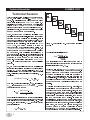
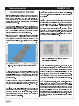
Technical Newsletter SUMMER 2003 Technical Session This Technical Session explains how the brake system on a 3-D simulation model (e.g., SIMON, EDVSM) Pedal Force Table (Force ) Pedal Ratio æ Press ö ç ÷ è Force ø works. 3-D simulation users will note that the driver brake table includes Pedal Force the option (2-D Pro Valve æ Press ö ç ÷ è Press ø simulations, not having a brake system model, include only the Wheel Force and % Available Friction options; ABS Sys æ Press ö ç ÷ è Press ø although these options may be available in some 3-D simulation models, they reduce the quality of the results Brake Torque and EDC does not recommend their use). æ ç è The 3-D brake system model in the simulation works Ratio Torque ö ÷ Press ø just like it does in a real vehicle. It starts with the driver Brake Torque (Torque ) pressing the brake pedal (in the simulation, this is presented as a table of brake pedal force vs. time). The master cylinder converts this force to brake system Brake pressure (in the simulation, this is called the Pedal Ratio). The system pressure may then be Figure 1 - Schematic flow of 3-D brake system simulation model reduced through a proportioning valve (modeled by a Threshold Pressure and Proportion Ratio). Next, the system pressure may be modulated at each wheel by an ABS system. This modulation is controlled by a The tire longitudinal slip is then: computer software algorithm in the simulation, just as it Slip = is on the actual vehicle. Finally, the system pressure is converted to brake torque by the assembly. The simulation calls this the Ratio. wheel brake VWheel Center Brake Torque The entire process is shown schematically in Figure 1. The tires friction (mu vs slip) data are then used to determine directly for the start of the next timestep the So, how does the resulting brake torque actually result in braking? In addition to equations of motion for linear motion VWheel Center - VxTire (X,Y,Z) and rotation (roll, pitch, yaw), 3-D simulations also have equations of motion for wheel spin. Application of first principles to wheel spin, W Wheel , results in: longitudinal braking force, Earlier we said that the Friction FxTire. Wheel Force and % Available brake table options were not recommended. It is now clear why: Use of either of these methods bypasses completely the wheel spin equations of motion. Any details related to tire spin dynamics are completely lost. Obviously, ABS simulation is also not && SM = Brake Torque - FxTire = ISpin W Wheel From this, wheel spin acceleration, && W Wheel , possible when either of these options is used (refer to the December 2001 Technical Newsletter for more is calculated Ispin is contstant and Brake Torque and FxTire for the details). ( current timestep are known): A question sometimes asked by new 3-D users is, How can I tell how much pedal force to use? There are a && W Wheel = BrakeTorque - FxTire couple of ways to answer this question. First, you have your ISpin common sense and years of actual driving experience. Think about it: You probably apply around 10 lb during a normal brake application, and maybe 50 Numerical integration is used to update the spin velocity lb of the wheel for the start of the next timestep. Using this analytical type, heres a method for you: First, create a patch is calculated: VxTire, RTire, more) during heavy braking. If youre the (also brake table that varies from zero force at time zero, and at the tire contact increases to 100 lb at 5 seconds. Start the vehicle at a spin velocity and the current tire radius, known), the linear velocity, (or high speed, say 80 mph, and execute the run. Then produce a graph of Forward Acceleration vs Brake VxTire = W Wheel × RTire & 2 Pedal Force. Voila! You now know precisely how hard to press the brake to achieve a desired deceleration.