1
R&S®FPS-K10 GSM Measurement User Manual (;ÚâÞ2) User Manual Test & Measurement 1176.8480.02 ─ 06 This manual applies to the following R&S®FPS models with firmware version 1.30 and higher: ● R&S®FPS4 (1319.2008K04) ● R&S®FPS7 (1319.2008K07) ● R&S®FPS13 (1319.2008K13) ● R&S®FPS30 (1319.2008K30) ● R&S®FPS40 (1319.2008K40) The following firmware options are described: ● R&S FPS-K10 (1321.4091.02) The firmware of the instrument makes use of several valuable open source software packages. For information, see the "Open Source Acknowledgement" on the user documentation CD-ROM (included in delivery). Rohde & Schwarz would like to thank the open source community for their valuable contribution to embedded computing. © 2015 Rohde & Schwarz GmbH & Co. KG Mühldorfstr. 15, 81671 München, Germany Phone: +49 89 41 29 - 0 Fax: +49 89 41 29 12 164 E-mail: [email protected] Internet: www.rohde-schwarz.com Subject to change – Data without tolerance limits is not binding. R&S® is a registered trademark of Rohde & Schwarz GmbH & Co. KG. Trade names are trademarks of the owners. The following abbreviations are used throughout this manual: R&S®FPS is abbreviated as R&S FPS. R&S®FPS-K10 Contents Contents 1 Preface.................................................................................................... 7 1.1 About this Manual......................................................................................................... 7 1.2 Documentation Overview............................................................................................. 7 1.3 Typographical Conventions.........................................................................................9 2 Welcome to the GSM Application.......................................................10 2.1 Starting the GSM Application.................................................................................... 10 2.2 Understanding the Display Information....................................................................12 3 About the Measurement...................................................................... 15 4 Measurements and Result Displays...................................................16 4.1 GSM I/Q (Modulation Accuracy, etc.) Measurement Results.................................. 16 4.2 Multicarrier Wideband Noise Measurements........................................................... 33 5 Basics on GSM Measurements...........................................................45 5.1 Relevant Digital Standards.........................................................................................45 5.2 Short introduction to GSM (GMSK, EDGE and EDGE Evolution)........................... 45 5.3 Short Introduction to VAMOS.................................................................................... 49 5.4 AQPSK Modulation..................................................................................................... 51 5.5 Trigger settings........................................................................................................... 52 5.6 Defining the Scope of the Measurement...................................................................53 5.7 Overview of filters in the R&S FPS GSM application...............................................55 5.8 Dependency of Slot Parameters................................................................................ 59 5.9 Definition of the Symbol Period.................................................................................59 5.10 Synchronization.......................................................................................................... 63 5.11 Timeslot Alignment.....................................................................................................65 5.12 Delta to Sync Values...................................................................................................67 5.13 Limit Checks................................................................................................................68 5.14 Impact of the "Statistic Count".................................................................................. 70 5.15 Multicarrier and Wideband Noise.............................................................................. 71 5.16 Automatic Carrier Detection...................................................................................... 81 5.17 GSM in MSRA Operating Mode..................................................................................82 6 Configuration........................................................................................85 User Manual 1176.8480.02 ─ 06 3 R&S®FPS-K10 Contents 6.1 Multiple Measurement Channels and Sequencer Function.................................... 85 6.2 Display Configuration.................................................................................................87 6.3 Modulation Accuracy Measurement Configuration................................................. 87 6.4 Multicarrier Wideband Noise (MCWN) Measurements.......................................... 130 7 Analysis.............................................................................................. 158 7.1 Result Configuration.................................................................................................158 7.2 Zoom Functions........................................................................................................ 164 8 I/Q Data Import and Export................................................................166 8.1 Import/Export Functions.......................................................................................... 166 8.2 How to Export and Import I/Q Data..........................................................................167 9 How to Perform Measurements in the GSM Application................170 9.1 How to Perform a Basic Measurement on GSM Signals....................................... 170 9.2 How to Determine Modulation Accuracy Parameters for GSM Signals............... 171 9.3 How to Analyze the Power in GSM Signals............................................................ 173 9.4 How to Analyze the Spectrum of GSM Signals...................................................... 174 10 Optimizing and Troubleshooting the Measurement....................... 177 10.1 Improving Performance............................................................................................177 10.2 Improving EVM Accuracy.........................................................................................177 10.3 Optimizing Limit Checks.......................................................................................... 178 10.4 Error Messages......................................................................................................... 179 11 Remote Commands to Perform GSM Measurements.....................180 11.1 Introduction............................................................................................................... 180 11.2 Common Suffixes......................................................................................................185 11.3 Activating GSM Measurements............................................................................... 185 11.4 Selecting the Measurement......................................................................................190 11.5 Configuring and Performing GSM I/Q Measurements........................................... 190 11.6 Configuring and Performing MCWN Measurements............................................. 240 11.7 Analyzing GSM Measurements................................................................................247 11.8 Retrieving Results.....................................................................................................268 11.9 Importing and Exporting I/Q Data and Results...................................................... 316 11.10 Status Reporting System......................................................................................... 317 11.11 Troubleshooting........................................................................................................322 User Manual 1176.8480.02 ─ 06 4 R&S®FPS-K10 Contents 11.12 Deprecated Commands (Commands for Compatibility)....................................... 323 11.13 Programming Examples........................................................................................... 331 A Annex: Reference...............................................................................345 A.1 List of abbreviations................................................................................................. 345 A.2 I/Q Data File Format (iq-tar)......................................................................................346 List of Commands..............................................................................352 Index....................................................................................................361 User Manual 1176.8480.02 ─ 06 5 R&S®FPS-K10 User Manual 1176.8480.02 ─ 06 Contents 6 R&S®FPS-K10 Preface About this Manual 1 Preface 1.1 About this Manual This GSM Measurements User Manual provides all the information specific to the application. All general instrument functions and settings common to all applications and operating modes are described in the main R&S FPS User Manual. The main focus in this manual is on the measurement results and the tasks required to obtain them. The following topics are included: ● Welcome to the GSM Application Introduction to and getting familiar with the application ● GSM I/Q (Modulation Accuracy, etc.) Measurement Results Details on supported measurements and their result types ● Basics on GSM Measurements Background information on basic terms and principles in the context of the measurement ● Modulation Accuracy Measurement Configuration and Analysis A concise description of all functions and settings available to configure measurements and analyze results with their corresponding remote control command ● I/Q Data Import and Export Description of general functions to import and export raw I/Q (measurement) data ● How to Perform Measurements in the GSM Application The basic procedure to perform each measurement and step-by-step instructions for more complex tasks or alternative methods ● Remote Commands to Perform GSM Measurements Remote commands required to configure and perform GSM measurements in a remote environment, sorted by tasks (Commands required to set up the environment or to perform common tasks on the instrument are provided in the main R&S FPS User Manual) Programming examples demonstrate the use of many commands and can usually be executed directly for test purposes ● List of remote commands Alpahabetical list of all remote commands described in the manual ● Index 1.2 Documentation Overview The user documentation for the R&S FPS consists of the following parts: ● Printed Getting Started manual ● Online Help system on the instrument ● Documentation CD-ROM with: User Manual 1176.8480.02 ─ 06 7 R&S®FPS-K10 Preface Documentation Overview – Getting Started – User Manuals for base unit and firmware applications – Service Manual – Release Notes – Data sheet and product brochures Online Help The Online Help is embedded in the instrument's firmware. It offers quick, context-sensitive access to the complete information needed for operation and programming. Online help is available using the icon on the toolbar of the R&S FPS. Getting Started This manual is delivered with the instrument in printed form and in PDF format on the CD-ROM. It provides the information needed to set up and start working with the instrument. Basic operations and handling are described. Safety information is also included. The Getting Started manual in various languages is also available for download from the Rohde & Schwarz website, on the R&S FPS product page at http://www.rohdeschwarz.com/product/FPS.html. User Manuals User manuals are provided for the base unit and each additional (firmware) application. The user manuals are available in PDF format - in printable form - on the Documentation CD-ROM delivered with the instrument. In the user manuals, all instrument functions are described in detail. Furthermore, they provide a complete description of the remote control commands with programming examples. The user manual for the base unit provides basic information on operating the R&S FPS in general, and the Spectrum application in particular. Furthermore, the software functions that enhance the basic functionality for various applications are described here. An introduction to remote control is provided, as well as information on maintenance, instrument interfaces and troubleshooting. In the individual application manuals, the specific instrument functions of the application are described in detail. For additional information on default settings and parameters, refer to the data sheets. Basic information on operating the R&S FPS is not included in the application manuals. All user manuals are also available for download from the Rohde & Schwarz website, on the R&S FPS product page at http://www2.rohde-schwarz.com/product/FPS.html. Service Manual This manual is available in PDF format on the Documentation CD-ROM delivered with the instrument. It describes how to check compliance with rated specifications, instrument function, repair, troubleshooting and fault elimination. It contains all information required for repairing the R&S FPS by replacing modules. User Manual 1176.8480.02 ─ 06 8 R&S®FPS-K10 Preface Typographical Conventions Release Notes The release notes describe the installation of the firmware, new and modified functions, eliminated problems, and last minute changes to the documentation. The corresponding firmware version is indicated on the title page of the release notes. The most recent release notes are also available for download from the Rohde & Schwarz website, on the R&S FPS product page at http://www2.rohde-schwarz.com/ product/FPS.html > Downloads > Firmware. 1.3 Typographical Conventions The following text markers are used throughout this documentation: Convention Description "Graphical user interface elements" All names of graphical user interface elements on the screen, such as dialog boxes, menus, options, buttons, and softkeys are enclosed by quotation marks. KEYS Key names are written in capital letters. File names, commands, program code File names, commands, coding samples and screen output are distinguished by their font. Input Input to be entered by the user is displayed in italics. Links Links that you can click are displayed in blue font. "References" References to other parts of the documentation are enclosed by quotation marks. User Manual 1176.8480.02 ─ 06 9 R&S®FPS-K10 Welcome to the GSM Application Starting the GSM Application 2 Welcome to the GSM Application The R&S FPS-K10 is a firmware application that adds functionality to perform GSM measurements to the R&S FPS. The R&S FPS-K10 features: ● Measurements on downlink or uplink signals according to the Third Generation Partnership Project (3GPP) standards for GSM/EDGE, EDGE Evolution (EGPRS2) and Voice services over Adaptive Multi-user Channels on One Slot (VAMOS) ● Measurement in time, frequency or I/Q domains ● Measurements of mobile devices (MS), single carrier and multicarrier base transceiver stations (BTS) ● Measurement of signals ith GMSK, AQPSK, QPSK, 8PSK, 16QAM and 32QAM modulation, normal or higher symbol rate ● Measurement of signals using different Tx filters (e.g. narrow and wide pulse) ● Measurements for Power vs Time, Modulation Accuracy and Modulation and Transient Spectrum as required in the standard ● Measurements of wideband noise and intermodulation products in multicarrier operation (as defined in 3GPP TS 51.021, chapter 6.12) This user manual contains a description of the functionality that the application provides, including remote control operation. All functions not discussed in this manual are the same as in the base unit and are described in the R&S FPS User Manual. The latest version is available for download at the product homepage http://www2.rohde-schwarz.com/product/FPS.html. Installation You can find detailed installation instructions in the R&S FPS Getting Started manual or in the Release Notes. 2.1 Starting the GSM Application GSM measurements are performed in a separate application on the R&S FPS. User Manual 1176.8480.02 ─ 06 10 R&S®FPS-K10 Welcome to the GSM Application Starting the GSM Application Manual operation via an external monitor and mouse Although the R&S FPS does not have a built-in display, it is possible to operate it interactively in manual mode using a graphical user interface with an external monitor and a mouse connected. It is recommended that you use the manual mode initially to get familiar with the instrument and its functions before using it in pure remote mode. Thus, this document describes in detail how to operate the instrument manually using an external monitor and mouse. The remote commands are described in the second part of the document. For details on manual operation see the R&S FPS Getting Started manual. To activate the GSM application 1. Select the MODE key. A dialog box opens that contains all operating modes and applications currently available on your R&S FPS. 2. Select the "GSM" item. The R&S FPS opens a new measurement channel for the GSM application. The measurement is started immediately with the default settings. It can be configured in the GSM "Overview" dialog box, which is displayed when you select the "Overview" softkey from any menu (see chapter 6.3.2, "Configuration Overview", on page 90). Remote command: INSTrument[:SELect] on page 189 Multiple Measurement Channels and Sequencer Function When you activate an application, a new measurement channel is created which determines the measurement settings for that application. The same application can be activated with different measurement settings by creating several channels for the same application. The number of channels that can be configured at the same time depends on the available memory on the instrument. Only one measurement channel can be active at any time. However, in order to perform the configured measurements consecutively, a Sequencer function is provided. When the Sequencer is activated, the measurements configured in the currently active channels are performed one after the other in the order of the tabs. The currently active measurement is indicated by a symbol in the tab label. The result displays of the individual channels are updated in the tabs as the measurements are performed. Sequential operation itself is independent of the currently displayed tab. User Manual 1176.8480.02 ─ 06 11 R&S®FPS-K10 Welcome to the GSM Application Understanding the Display Information See also the note on using the Sequencer function in MSRA operating mode in chapter 5.17, "GSM in MSRA Operating Mode", on page 82. For details on the Sequencer function see the R&S FPS User Manual. 2.2 Understanding the Display Information The following figure shows a measurement diagram during analyzer operation. All different information areas are labeled. They are explained in more detail in the following sections. 1 2+3 4 5 6 = = = = = Channel bar for firmware and measurement settings Window title bar with diagram-specific (trace) information Diagram area Diagram footer with diagram-specific information, depending on measurement Instrument status bar with error messages, progress bar and date/time display MSRA operating mode In MSRA operating mode, additional tabs and elements are available. An orange background behind the measurement channel tabs indicates that you are in MSRA operating mode. For details on the MSRA operating mode see chapter 5.17, "GSM in MSRA Operating Mode", on page 82 and the R&S FPS MSRA User Manual. Channel bar information In the GSM application, the R&S FPS shows the following settings for the default I/Q measurement: User Manual 1176.8480.02 ─ 06 12 R&S®FPS-K10 Welcome to the GSM Application Understanding the Display Information Table 2-1: Information displayed in the channel bar in the GSM application for the default I/Q measurement Ref Level Reference level (m.+el.) Att Mechanical and electronic RF attenuation Offset Reference level offset (if available) Freq / ARFCN Center frequency for the GSM signal / Absolute Radio Frequency Channel Number (if available) Device / Band Device type and frequency band used by the DUT as defined in the Signal Description settings Slot Scope Minimized visualization of the frame configuration and slots to be measured (see chapter 5.6, "Defining the Scope of the Measurement", on page 53) SGL The sweep is set to single sweep mode. Count Number of frames already evaluated / Total number of frames required for statistical evaluation (Statistic Count) (For Statistic Count > 1) TRG Trigger source (if not "Free Run") and used trigger bandwidth (for IF, RF, IP power triggers) or trigger offset (for external triggers) In addition, the channel bar also displays information on instrument settings that affect the measurement results even though this is not immediately apparent from the display of the measured values (e.g. transducer settings). This information is displayed only when applicable for the current application. For details see the R&S FPS Getting Started manual. Window title bar information For each diagram, the header provides the following information: Fig. 2-1: Window title bar information in the Pulse application 1 2 3 4 6 = = = = = Window number Window type Trace color Trace number Trace mode Diagram footer information The diagram footer (beneath the diagram) contains the start and stop values for the displayed time, frequency or symbol range. User Manual 1176.8480.02 ─ 06 13 R&S®FPS-K10 Welcome to the GSM Application Understanding the Display Information Status bar information Global instrument settings, the instrument status and any irregularities are indicated in the status bar beneath the diagram. Furthermore, the progress of the current operation is displayed in the status bar. User Manual 1176.8480.02 ─ 06 14 R&S®FPS-K10 About the Measurement 3 About the Measurement A basic GSM measurement in the R&S FPS GSM application includes a power vs time and a spectrum measurement, as well as modulation accuracy (e.g. EVM, phase error) for a GSM signal as defined by the relevant 3GPP standards. The I/Q data from the GSM signal applied to the RF input of the R&S FPS is captured for a specified measurement time. This data is demodulated and synchronized with a reference signal to identify the individual frames and slots. The slots of interest are then analyzed in order to display the spectral and power results either graphically or numerically, and to calculate the modulation parameters. The standard distinguishes between single-slot and multi-slot measurements. Singleslot measurements analyze one slot - referred to as the "Slot to measure" - within the GSM frame (which consists of 8 slots in total). Modulation-specific parameters such as the phase error, EVM, or spectrum due to modulation are determined on a per-slot basis. Multi-slot measurements, on the other hand, analyze a slot scope of up to 8 consecutive slots, each of which has different burst modulation characteristics. Power vs time limit checks and the transient spectrum measurements, for example, are determined for multiple slots. Statistical evaluation of several measurements is also possible. Finally, the GSM measurement results can be exported to other applications. User Manual 1176.8480.02 ─ 06 15 R&S®FPS-K10 Measurements and Result Displays GSM I/Q (Modulation Accuracy, etc.) Measurement Results 4 Measurements and Result Displays The R&S FPS GSM application provides two different measurements in order to determine the parameters described by the GSM specifications. The default GSM I/Q measurement captures the I/Q data from the GSM signal. The I/Q data includes magnitude and phase information, which allows the R&S FPS GSM application to demodulate signals and determine various characteristic signal parameters such as the modulation accuracy, power vs time, modulation and transient spectrum in just one measurement. For multicarrier measurements, some parameters required by the GSM standard require a frequency sweep with varying resolution bandwidths. Thus, a new separate measurement is provided by the R&S FPS GSM application to determine the wideband noise in multicarrier measurement setups. For details on selecting measurements see "Selecting the measurement type" on page 85. ● ● GSM I/Q (Modulation Accuracy, etc.) Measurement Results..................................16 Multicarrier Wideband Noise Measurements.......................................................... 33 4.1 GSM I/Q (Modulation Accuracy, etc.) Measurement Results The I/Q data that was captured by the default GSM (Modulation Accuracy, etc.) measurement can be evaluated using different methods. All evaluation methods available for the GSM measurements are displayed in the selection bar in SmartGrid mode. To activate SmartGrid mode, do one of the following: ● Select the "SmartGrid" icon from the toolbar. ● Select the "Display" button in the configuration "Overview". ● Select the "Display Config" softkey from the MEAS CONFIG menu. ● Press the MEAS key. For details on working with the SmartGrid see the R&S FPS Getting Started manual. By default, the GSM measurement results for I/Q measurements are displayed in the following windows: ● Magnitude Capture ● PvT Full Burst ● Modulation Accuracy User Manual 1176.8480.02 ─ 06 16 R&S®FPS-K10 Measurements and Result Displays GSM I/Q (Modulation Accuracy, etc.) Measurement Results ● Power vs Slot The following evaluation methods are available for GSM I/Q measurements: Constellation................................................................................................................. 17 EVM.............................................................................................................................. 17 Magnitude Capture........................................................................................................18 Magnitude Error............................................................................................................ 19 Marker Table................................................................................................................. 20 Modulation Accuracy.....................................................................................................20 Modulation Spectrum Graph......................................................................................... 22 Modulation Spectrum Table.......................................................................................... 23 Phase Error................................................................................................................... 25 Power vs Slot................................................................................................................ 26 PvT Full Burst................................................................................................................27 Transient Spectrum Graph............................................................................................29 Transient Spectrum Table.............................................................................................30 Trigger to Sync Graph...................................................................................................31 Trigger to Sync Table....................................................................................................33 Constellation The complex source signal is displayed as an X/Y diagram. The application analyzes the specified slot over the specified number of bursts. Remote command: LAY:ADD? '1',RIGH,CONS, see LAYout:ADD[:WINDow]? on page 249 EVM Displays the error vector magnitude over time for the Slot to Measure. User Manual 1176.8480.02 ─ 06 17 R&S®FPS-K10 Measurements and Result Displays GSM I/Q (Modulation Accuracy, etc.) Measurement Results Remote command: LAY:ADD:WIND '2',RIGH,ETIMe see LAYout:ADD[:WINDow]? on page 249 Results: TRACe<n>[:DATA]? on page 270 Magnitude Capture Displays the power vs. time trace of the captured I/Q data. Pre-trigger samples are not displayed. The analyzed slot scopes (1 to 8 slots of a single GSM frame) are indicated by a green bar, the Slot to Measure in each frame by a blue bar at the bottom of the diagram. For details see chapter 5.6, "Defining the Scope of the Measurement", on page 53. For negative trigger offsets, the trigger is displayed as a vertical red line labeled "TRG". User Manual 1176.8480.02 ─ 06 18 R&S®FPS-K10 Measurements and Result Displays GSM I/Q (Modulation Accuracy, etc.) Measurement Results Remote command: LAY:ADD:WIND '2',RIGH,MCAP see LAYout:ADD[:WINDow]? on page 249 Results: FETCh:MCAPture:SLOTs:SCOPe? on page 276 FETCh:MCAPture:SLOTs:MEASure? on page 276 TRACe<n>[:DATA]? on page 270 Magnitude Error Displays the magnitude error over time for the Slot to Measure. Remote command: LAY:ADD:WIND '2',RIGH,MERR see LAYout:ADD[:WINDow]? on page 249 Results: TRACe<n>[:DATA]? on page 270 User Manual 1176.8480.02 ─ 06 19 R&S®FPS-K10 Measurements and Result Displays GSM I/Q (Modulation Accuracy, etc.) Measurement Results Marker Table Displays a table with the current marker values for the active markers. This table may be displayed automatically if configured accordingly (see "Marker Table Display" on page 162). Remote command: LAY:ADD? '1',RIGH, MTAB, see LAYout:ADD[:WINDow]? on page 249 Results: CALCulate<n>:MARKer<m>:X on page 315 CALCulate<n>:MARKer<m>:Y? on page 315 Modulation Accuracy Displays the numeric values of the fundamental modulation characteristics of the signal to be analyzed in the vector (I/Q) domain: error vector magnitude (EVM), magnitude and phase error, IQ imbalance, etc. The following modulation parameters are determined: User Manual 1176.8480.02 ─ 06 20 R&S®FPS-K10 Measurements and Result Displays GSM I/Q (Modulation Accuracy, etc.) Measurement Results Table 4-1: Modulation accuracy parameters Parameter Description SCPI query for result value EVM Error vector magnitude for the Slot to Measure READ:BURSt[:MACCuracy][: EVM]:PEAK:<Resulttype>? RMS and peak error values for the current frame, in perREAD:BURSt[:MACCuracy][: cent EVM]:RMS:<Resulttype>? 95%ile: error value (in percent) below which 95% of all READ:BURSt[: EVM results for all frames in entire measurement fall MACCuracy]PERCentile:EVM? Mag Error Magnitude error for the Slot to Measure Phase Error Phase error for the Slot to Measure Origin Offset Suppression READ:BURSt[:MACCuracy]: MERRor:PEAK:<Resulttype>? RMS and peak error values for the current frame, in perREAD:BURSt[:MACCuracy]: cent MERRor:RMS:<Resulttype>? 95%ile: error value (in percent) below which 95% of all Magnitude Error results for all frames in entire measure- READ:BURSt[: MACCuracy]PERCentile: ment fall MERRor? READ:BURSt[:MACCuracy]: PERRor:PEAK:<Resulttype>? RMS and peak error values for the current frame, in perREAD:BURSt[:MACCuracy]: cent PERRor:RMS:<Resulttype>? 95%ile: error value (in percent) below which 95% of all Phase Error results for all frames in entire measurement READ:BURSt[: MACCuracy]PERCentile: fall PERRor? Origin offset suppression for the demodulated signal in the Slot to Measure; Indicates the suppression of the DC carrier; the higher the suppression, the better the DUT READ:BURSt[:MACCuracy]: OSUPpress:<Resulttype>? I/Q offset for the demodulated signal in the Slot to Measure READ:BURSt[:MACCuracy]: IQOFfset:<Resulttype>? A measure for gain imbalances and quadrature errors between the inplace and quadrature components of the signal. READ:BURSt[:MACCuracy]: IQIMbalance:<Resulttype>? Frequency error of the center frequency currently measured in the Slot to Measure READ:BURSt[:MACCuracy]: FERRor:<Resulttype>? Average power measured in the slot READ:BURSt[:MACCuracy]: BPOWer:<Resulttype>? Indicates how much the amplitude decreases over a measured slot READ:BURSt[:MACCuracy]: ADRoop:<Resulttype>? [dB] I/Q Offset [%] I/Q Imbalance [%] Frequency Error [Hz] Burst Power [dBm] Amplitude Droop [dB] User Manual 1176.8480.02 ─ 06 21 R&S®FPS-K10 Measurements and Result Displays GSM I/Q (Modulation Accuracy, etc.) Measurement Results The R&S FPS GSM application also performs statistical evaluation over a specified number of results (see "Statistic Count" on page 117). To do so, the same slot is evaluated in multiple frames, namely in the number specified by the "Statistic Count". The default value is 200 in accordance with the GSM standard. For each parameter, the following results are displayed: Table 4-2: Calculated summary results Result type Description SCPI query for result value Current Value for currently measured frame only READ:BURSt[:MACCuracy]: <Parameter>:CURRent? Average Linear average value of "Current" results from the speci- READ:BURSt[:MACCuracy]: <Parameter>:AVERage? fied number of frames Exception: The average of the "Origin Offset Suppression" is the linear average of the power ratio, converted to dBm subsequently Peak Maximum value of "Current" results from specified number of frames READ:BURSt[:MACCuracy]: <Parameter>:MAXimum? Exception: The peak of the "Origin Offset Suppression" is the minimum value, as this represents the worst case, which needs to be detected Std Dev Standard deviation of "Current" results for specified number of frames READ:BURSt[:MACCuracy]: <Parameter>:SDEViation? Remote command: LAY:ADD:WIND '2',RIGH,MACC see LAYout:ADD[:WINDow]? on page 249 Results: READ:BURSt[:MACCuracy]:ALL on page 280 chapter 11.8.4, "Modulation Accuracy Results", on page 277 Modulation Spectrum Graph The modulation spectrum evaluates the power vs frequency trace of a certain part of the burst (50 to 90 % of the useful part, excluding the training sequence TSC) by measuring the average power in this part over several frames at certain fixed frequency offsets. The "Modulation Spectrum Graph" displays the measured power levels as a trace against the frequencies. The measured values can be checked against defined limits; the limit lines are indicated as red lines in the diagram. The result of the limit check ("PASS"/"FAIL") are shown at the top of the diagram. Note: The GSM standards define both absolute and relative limits for the spectrum. The limit check is considered to fail if both limits are exceeded. User Manual 1176.8480.02 ─ 06 22 R&S®FPS-K10 Measurements and Result Displays GSM I/Q (Modulation Accuracy, etc.) Measurement Results Note: The graphical results only provide an overview of the spectrum. For a detailed conformance check of the DUT to the GSM standard, use the "Modulation Spectrum Table" evaluation, which uses the 5-pole filter required by the 3GPP standard. The numeric results of the modulation spectrum evaluation are displayed in the "Modulation Spectrum Table" on page 23. The following default settings are used for a "Modulation Spectrum" evaluation. Table 4-3: Default settings for a "Modulation Spectrum" evaluation Setting Default Measurement Scope The slot selected as Slot to Measure Averaging Configuration Number of bursts as selected in Statistic Count Limit Check According to standard: Limit check of average (Avg) trace See chapter 5.13.1, "Limit Check for Modulation Spectrum", on page 68 Note: Modulation RBW at 1800 kHz. For the "Modulation Spectrum Graph" both the RBW and VBW are set to 30 kHz. Remote command: LAY:ADD:WIND '2',RIGH,MSFD see LAYout:ADD[:WINDow]? on page 249 Results: TRACe<n>[:DATA]? on page 270 CALCulate<n>:LIMit<k>:FAIL? on page 302 CALCulate<n>:LIMit<k>:UPPer[:DATA]? on page 303 CALCulate<n>:LIMit<k>:CONTrol:DATA? on page 302 Modulation Spectrum Table The modulation spectrum evaluates the power vs frequency trace of a certain part of the burst (50 to 90 % of the useful part, excluding the training sequence TSC) by measuring the average power in this part over several frames. The "Modulation Spectrum Table" displays the measured power levels and their offset to the limits defined by the standard as numeric results. Note: The GSM standards define both absolute and relative limits for the spectrum. The limit check is considered to fail if both limits are exceeded. User Manual 1176.8480.02 ─ 06 23 R&S®FPS-K10 Measurements and Result Displays GSM I/Q (Modulation Accuracy, etc.) Measurement Results Values that exceed both limits are indicated by red characters and an asterisk (*) next to the value, and a negative "Δ to Limit" value. Note: The graphical results of the modulation spectrum evaluation are displayed in the "Modulation Spectrum Graph" on page 22. The following values are displayed: Table 4-4: Modulation spectrum results Result Description Offset Fixed frequency offsets (from the center frequency) at which power is measured [kHz] Power Negative Offsets Power at the frequency offset to the left of the center frequency Levels are provided as: [dB]: relative power level [dBm]: absolute power level Δ to Limit: power difference to limit defined in standard; negative values indicate the power exceeds at least one of the limits Power Positive Offsets Power at the frequency offset to the right of the center frequency Levels are provided as: [dB]: relative power level [dBm]: absolute power level Δ to Limit: power difference to limit defined in standard; negative values indicate the power exceeds at least one of the limits Table 4-5: Frequencies and filter bandwidths in modulation spectrum measurements Offset Frequency (kHz) RBW (kHz) VBW (kHz) ± 100 30 30 ± 200 30 30 ± 250 30 30 ± 400 30 30 ± 600 30 30 User Manual 1176.8480.02 ─ 06 24 R&S®FPS-K10 Measurements and Result Displays GSM I/Q (Modulation Accuracy, etc.) Measurement Results Offset Frequency (kHz) RBW (kHz) VBW (kHz) ± 800 30 30 ± 1000 30 30 ± 1200 30 30 ± 1400 30 30 ± 1600 30 30 ± 1800 30 (single-carrier BTS); 30 (single-carrier BTS); 100 (multi-carrier BTS); 100 (multi-carrier BTS); Note: "Normal" vs "Wide" Modulation Spectrum measurements. In previous R&S signal and spectrum analyzers, both a "normal" and a "wide" modulation spectrum were available for GSM measurements. In the R&S FPS GSM application, only one evaluation is provided. The frequency range of the frequency list, however, can be configured to be "wider" or "narrower" (see "Modulation Spectrum Table: Frequency List" on page 127). The RBW and VBW are then adapted accordingly. Note: RBW at 1800 kHz. As opposed to previous R&S signal and spectrum analyzers, in which the RBW at 1800 kHz was configurable, the R&S FPS configures the RBW (and VBW) internally according to the selected frequency list (see "Modulation Spectrum Table: Frequency List" on page 127). For the "Modulation Spectrum Graph" both the RBW and VBW are set to 30 kHz. For the "Modulation Spectrum Table", they are set according to table 4-6, depending on the measured Device Type and the number of active carriers as defined in the "Signal Description" settings. Table 4-6: RBW settings for Modulation Spectrum Table measurements according to standard Offset Single-carrier BTS Multicarrier BTS (N=1) Multicarrier BTS (N>1) < 1.8 MHz 30 kHz 1) 30 kHz 3) 30 kHz 2) 30 kHz 4) 1.8 MHz 30 kHz 1) 100 kHz 3) 100 kHz 2) 100 kHz 5) > 1.8 MHz 100 kHz 3) 100 kHz 3) 100 kHz 2) 100 kHz 5) 1) See 3GPP TS 51.021 § 6.5.1.2 c) d) 2) See 3GPP TS 51.021 § 6.12.2 3) See 3GPP TS 51.021 § 6.5.1.2 f) Remote command: LAY:ADD:WIND '2',RIGH,MST see LAYout:ADD[:WINDow]? on page 249 Results: READ:SPECtrum:MODulation[:ALL]? on page 288 READ:SPECtrum:MODulation:REFerence[:IMMediate]? on page 289 Phase Error Displays the phase error over time. User Manual 1176.8480.02 ─ 06 25 R&S®FPS-K10 Measurements and Result Displays GSM I/Q (Modulation Accuracy, etc.) Measurement Results The following default settings are used for a "Phase Error vs Time" measurement. Setting Default Measurement Scope The slot selected as Slot to Measure Averaging Configuration Number of frames as selected in Statistic Count Limit Check None Remote command: LAY:ADD:WIND '2',RIGH,PERR see LAYout:ADD[:WINDow]? on page 249 Results: TRACe<n>[:DATA]? on page 270 Power vs Slot Displays the power per slot in the current frame and over all frames. The result of the (Power vs Time) limit check is also indicated. Note: The power is measured for inactive slots, but not for slots outside the slot scope (see chapter 5.6, "Defining the Scope of the Measurement", on page 53). The following power values are determined: User Manual 1176.8480.02 ─ 06 26 R&S®FPS-K10 Measurements and Result Displays GSM I/Q (Modulation Accuracy, etc.) Measurement Results Table 4-7: Measured power values for Power vs Slot results Value Description Slot Analyzed slot number in frame(s) SCPI query for result value [0..7] PvT Limit Power vs Time limit for the power vs time trace of the slot, defined by the standard READ:BURSt:SPOWer: SLOT<Slot>:LIMit:FAIL? on page 297 Delta to Sync The distance between the mid of the TSC and the TSC of the Slot to Measure [NSP] NSP stands for Normal Symbol Period, i.e. the duration of one symbol using a normal symbol rate (approx. 3.69μs). READ:BURSt:SPOWer: SLOT<Slot>:DELTatosync? on page 296 The measured "Delta to Sync" value has a resolution of 0.02 NSP. For details see chapter 5.12, "Delta to Sync Values", on page 67. Power Avg Average power in slot in current or all frames [dBm] READ:BURSt:SPOWer: SLOT<Slot>:CURRent:AVERage? on page 293 READ:BURSt:SPOWer: SLOT<Slot>:ALL:AVERage? on page 291 Power Peak Maximum power in slot in current or all frames [dBm] READ:BURSt:SPOWer: SLOT<Slot>:CURRent:MAXimum? on page 295 READ:BURSt:SPOWer: SLOT<Slot>:ALL:MAXimum? on page 292 Crest [dB] Crest factor in slot in current or all frames, i.e. Power Peak / Power Avg READ:BURSt:SPOWer: SLOT<Slot>:CURRent:CRESt? on page 294 READ:BURSt:SPOWer: SLOT<Slot>:ALL:CRESt? on page 291 Remote command: LAY:ADD:WIND '2',RIGH,PST see LAYout:ADD[:WINDow]? on page 249 Results: chapter 11.8.6, "Power vs Slot Results", on page 290 PvT Full Burst The Power vs Time evaluation determines the power of all slots (bursts) in the selected slot scope and performs a limit check of the power vs time trace against the specified PvT mask. The "PvT Full Burst" result display shows the power vs time trace, where the time axis corresponds to the selected slot scope. The PvT mask is indicated by red lines, and the overall result of the limit check is shown at the top of the diagram. Note: The result of the Power vs Time limit check for individual slots is indicated in the "Power vs Slot" on page 26 evaluation. User Manual 1176.8480.02 ─ 06 27 R&S®FPS-K10 Measurements and Result Displays GSM I/Q (Modulation Accuracy, etc.) Measurement Results Note: Full burst refers to the fact that the entire burst is displayed, including the rising and falling edges and the burst top. However, you can easily analyze the edges in more detail using the zoom functions (see chapter 7.2, "Zoom Functions", on page 164). The following default settings are used for a "Power vs Time" evaluation. Table 4-8: Default settings for a "Power vs Time" evaluation Setting Default Measurement Scope The slot scope defined by First Slot to measure and Number of Slots to measure Averaging Configuration Number of bursts as selected in Statistic Count Limit Check According to standard: ● The maximum (Max) trace is checked agains the upper limit. ● The minimum (Min) trace is checked against the lower limit. See chapter 5.13.3, "Limit Check for Power vs Time Results", on page 69 Remote command: LAY:ADD:WIND '2',RIGH,PTF see LAYout:ADD[:WINDow]? on page 249 Results: TRACe<n>[:DATA]? on page 270 TRACe<n>[:DATA]:X? on page 271 CALCulate<n>:LIMit<k>:FAIL? on page 302 CALCulate<n>:LIMit<k>:UPPer[:DATA]? on page 303 CALCulate<n>:LIMit<k>:CONTrol:DATA? on page 302 User Manual 1176.8480.02 ─ 06 28 R&S®FPS-K10 Measurements and Result Displays GSM I/Q (Modulation Accuracy, etc.) Measurement Results Transient Spectrum Graph The transient spectrum is very similar to the modulation spectrum evaluation; it evaluates the power vs frequency trace by measuring the power over several frames. However, as opposed to the modulation spectrum evaluation, the entire slot scope (defined by the Number of Slots to measure and the First Slot to measure) is evaluated in each frame, including the rising and falling burst edges, not just the useful part in the Slot to Measure. Furthermore, the number of fixed frequency offsets is lower, and the peak power is evaluated rather than the average power, as this measurement is used to determine irregularities. The "Transient Spectrum Graph" displays the measured power levels as a trace against the frequencies for the specified slots. The measured values can be checked against defined limits; the limit lines are indicated as red lines in the diagram. The result of the limit check ("PASS"/"FAIL") is shown at the top of the diagram. Note: The GSM standards define both absolute and relative limits for the spectrum. The limit check is considered to fail if both limits are exceeded. Note: The graphical results only provide an overview of the spectrum. For a detailed conformance check of the DUT to the GSM standard, use the "Transient Spectrum Table" evaluation, which uses the 5-pole filter required by the 3GPP standard. The numeric results of the modulation spectrum evaluation are displayed in the "Modulation Spectrum Table" on page 23. The following default settings are used for "Transient Spectrum" measurements. User Manual 1176.8480.02 ─ 06 29 R&S®FPS-K10 Measurements and Result Displays GSM I/Q (Modulation Accuracy, etc.) Measurement Results Setting Default Measurement Scope The slot scope defined by Number of Slots to measure and the First Slot to measure in the "Demodulation Settings" (see chapter 6.3.7.1, "Slot Scope", on page 118). Averaging Configuration Number of frames as selected in Statistic Count Limit Check Limit check of maximum (Max) trace See chapter 5.13.2, "Limit Check for Transient Spectrum", on page 69 Remote command: LAY:ADD:WIND '2',RIGH,TSFD see LAYout:ADD[:WINDow]? on page 249 Results: TRACe<n>[:DATA]? on page 270 CALCulate<n>:LIMit<k>:FAIL? on page 302 Transient Spectrum Table The transient spectrum evaluates the power vs frequency trace of the slot scope by measuring the power in these slots over several frames. For details see "Transient Spectrum Graph" on page 29. The "Transient Spectrum Table" displays the measured power levels and their offset to the limits defined by the standard as numeric results. Note: The GSM standards define both absolute and relative limits for the spectrum. The limit check is considered to fail if both limits are exceeded. Values that exceed both limits are indicated by red characters and an asterisk (*) next to the value, and a negative "Δ to Limit" value. Note: The graphical results of the transient spectrum evaluation are displayed in the "Transient Spectrum Graph" on page 29. The following values are displayed: User Manual 1176.8480.02 ─ 06 30 R&S®FPS-K10 Measurements and Result Displays GSM I/Q (Modulation Accuracy, etc.) Measurement Results Table 4-9: Modulation spectrum results Result Description Offset Fixed frequency offsets (from the center frequency) at which power is measured [kHz] Power Negative Offsets Power at the frequency offset to the left of the center frequency Levels are provided as: [dB]: relative power level [dBm]: absolute power level Δ to Limit: power difference to limit defined in standard; negative values indicate the power exceeds at least one of the limits Power Positive Offsets Power at the frequency offset to the right of the center frequency Levels are provided as: [dB]: relative power level [dBm]: absolute power level Δ to Limit: power difference to limit defined in standard; negative values indicate the power exceeds at least one of the limits Remote command: LAY:ADD:WIND '2',RIGH,TST see LAYout:ADD[:WINDow]? on page 249 Results: READ:SPECtrum:SWITching[:ALL]? on page 298 READ:SPECtrum:SWITching:REFerence[:IMMediate] on page 299 Trigger to Sync Graph The Trigger to Sync measurement determines the time between an external trigger event and the start of the first symbol of the TSC. The start of the first symbol of the TSC corresponds to the time 0 of the symbol period (see chapter 5.9, "Definition of the Symbol Period", on page 59). Only one result per data capture is provided. Therefore, it is useful to perform several data captures and average the results to obtain an accurate value (see "Statistic Count" on page 117). Both graphical and numeric (table) results are available. While the graphical results are mainly used to determine the required measurement settings, the numeric results provide the actual trigger to sync value, including statistical evaluation (see "Trigger to Sync Table" on page 33). User Manual 1176.8480.02 ─ 06 31 R&S®FPS-K10 Measurements and Result Displays GSM I/Q (Modulation Accuracy, etc.) Measurement Results Fig. 4-1: Trigger to Sync Graph The Trigger to Sync diagram shows two traces: ● ● Trace1: a histogram shows the probability density function (PDF) of all measured Trigger to Sync values. Obviously, the histogram can only provide reasonable results if several I/Q captures are performed and considered. In an ideal case (assuming no noise), the histogram would be a rectangle over the trigger sampling time. The histogram is helpful to determine the number of Trigger to Sync values to be averaged (Statistic Count) in order to obtain the required time resolution of the averaged Trigger to Sync value. The higher the statistic count, the more the graph becomes rectangular, and the higher the resolution of the averaged Trigger to Sync value becomes. Trace2: the second trace is superimposed on the histogram and visualizes the probability density function (PDF) of the average Trigger to Sync value and the standard deviation as provided in the Trigger to Sync table. This trace helps you judge the reliability of the averaged values in the table. The narrower this trace, the less the individual values deviate from the averaged result. if this trace is too wide, increase the Statistic Count. Note: The x-axis of the histogram indicates the individual Trigger to Sync values. Thus, the scaling must be very small, in the range of ns. However, since the value range, in particular the start value, of the possible results is not known, the x-axis must be adapted to the actual values after a number of measurements have taken place. This is done using the adaptive data size setting (see "Adaptive Data Size" on page 129). This setting defines how many measurements are performed before the x-axis is adapted to the measured values, and then fixed to that range. Remote command: LAY:ADD? '1',RIGH,TGSG, see LAYout:ADD[:WINDow]? on page 249 DISPlay:WINDow:TRACe1:MODE WRITe (for Histogram, see DISPlay[: WINDow<n>]:TRACe<t>:MODE on page 256 ) DISPlay:WINDow:TRACe2:MODE PDFavg (for PDF of average, see DISPlay[: WINDow<n>]:TRACe<t>:MODE on page 256) Results: TRACe<n>[:DATA]? on page 270 TRACe<n>[:DATA]:X? on page 271 User Manual 1176.8480.02 ─ 06 32 R&S®FPS-K10 Measurements and Result Displays Multicarrier Wideband Noise Measurements Trigger to Sync Table The Trigger to Sync measurement determines the time between an external trigger event and the start of the first symbol of the TSC. The start of the first symbol of the TSC corresponds to the time 0 of the symbol period (see chapter 5.9, "Definition of the Symbol Period", on page 59). Only one result per data capture is provided. Therefore, it is useful to perform several data captures and average the results to obtain an accurate value (see "Statistic Count" on page 117). Both graphical and numeric (table) results are available. While the graphical results are mainly used to determine the required measurement settings (see "Trigger to Sync Graph" on page 31), the numeric results provide the actual trigger to sync value, including statistical evaluation. Fig. 4-2: Trigger to Sync table The Trigger to Sync table shows the following values: Value Description Current Trigger to Sync value for current measurement in μs Average Trigger to Sync value averaged over the Statistic Count number of measurements Min Minimum Trigger to Sync value in the previous Statistic Count number of measurements Max Maximum Trigger to Sync value in the previous Statistic Count number of measurements Std Dev Standard deviation of the individual Trigger to Sync values to the average value Remote command: LAY:ADD? '1',RIGH,TGST, see LAYout:ADD[:WINDow]? on page 249 Results: chapter 11.8.8, "Trigger to Sync Results", on page 300 4.2 Multicarrier Wideband Noise Measurements The I/Q data captured by the default GSM I/Q measurement includes magnitude and phase information, which allows the R&S FPS GSM application to demodulate signals and determine various characteristic signal parameters such as the modulation accuracy, modulation or transient spectrum in just one measurement. As the result of a swept measurement, on the other hand, the signal cannot be demodulated based on the power vs. frequency trace data. Frequency sweep measurements can tune on a constant frequency ("Zero span measurement") or sweep a frequency range ("Frequency sweep measurement"). User Manual 1176.8480.02 ─ 06 33 R&S®FPS-K10 Measurements and Result Displays Multicarrier Wideband Noise Measurements For multicarrier measurements, the GSM standard defines limits for some parameters concerning noise and intermodulation products. Thus, a new separate measurement is provided by the R&S FPS GSM application: the Multicarrier Wideband Noise Measurement (MCWN). This measurement comprises: ● I/Q based measurements on the carriers to determine their power levels and reference powers ● Frequency sweeps with RBWs of 100 kHz (to measure wideband noise) and 300 kHz (to measure intermodulation products) ● Gated zero span measurements with an RBW of 30 kHz to measure narrowband noise MCWN measurements and MSRA mode MCWN measurements are only available in Signal and Spectrum Analyzer operating mode, not in MSRA mode (see chapter 5.17, "GSM in MSRA Operating Mode", on page 82). For more information on MCWN measurements see also chapter 5.15, "Multicarrier and Wideband Noise", on page 71. ● Multicarrier Evaluation Methods..............................................................................34 4.2.1 Multicarrier Evaluation Methods The GSM multicarrier wideband noise measurement can be evaluated using different methods. All evaluation methods available for the measurement are displayed in the selection bar in SmartGrid mode. For details on working with the SmartGrid see the R&S FPS Getting Started manual. By default, the MWCN measurement results are displayed in the following windows: ● Spectrum Graph ● Carrier Power Table The following evaluation methods are available for GSM MCWN measurements: Spectrum Graph............................................................................................................35 Carrier Power Table...................................................................................................... 36 Inner IM Table............................................................................................................... 37 Outer IM Table.............................................................................................................. 38 Inner Narrow Band Table.............................................................................................. 39 Outer Narrowband Table...............................................................................................39 Inner Wideband Table...................................................................................................41 Outer Wideband Table.................................................................................................. 42 Marker Table................................................................................................................. 44 User Manual 1176.8480.02 ─ 06 34 R&S®FPS-K10 Measurements and Result Displays Multicarrier Wideband Noise Measurements Spectrum Graph Displays the level results for the frequencies in the defined frequency span (typically the Tx band). The trace is calculated from a frequency sweep with a 100 kHz RBW and one sweep with a 300 kHz RBW. The displayed trace is averaged over the Noise Average Count number of noise measurements. The narrowband noise results (if available) are indicated as vertical green bars at the distinct measurement frequencies (see "Outer Narrowband Table" on page 39). The results of the limit check are also indicated in the diagram (see also chapter 5.15.4, "Limit Check for MCWN Results", on page 75): Table 4-10: Limit line checks Label Possible values Description / Limit line suffix (<k>) Limit check PASS | FAIL Overall limit check for all limit lines Wideband Noise PASS | FAIL Limit check for wideband noise (trace) (<current> exceptions) (Number of detected exceptions; provided only if exceptions are enabled) <k> = 1 IM 100 kHz PASS | FAIL Limit check for intermodulation at 100 kHz (Number of detected exceptions; provided only if exceptions are enabled) <k> = 2 IM 300 kHz PASS | FAIL Limit check for intermodulation at 300 kHz <k> = 3 Narrowband Noise PASS | FAIL Limit check for narrowband noise <k> = 4 User Manual 1176.8480.02 ─ 06 35 R&S®FPS-K10 Measurements and Result Displays Multicarrier Wideband Noise Measurements Label Possible values Description / Limit line suffix (<k>) Exceptions: <current> < <maximum> PASS | FAIL Number of bands with exceptions in range A (currently detected vs. maximum allowed); provided only if exceptions are enabled <k> = 5 Exceptions: <current> < <maximum> PASS | FAIL Number of bands with exceptions in range B (currently detected vs. maximum allowed); provided only if exceptions are enabled <k> = 6 Remote command: LAY:ADD? '1',RIGH,WSFDomain, see LAYout:ADD[:WINDow]? on page 249 Results: TRACe:DATA? TRACe1, see TRACe<n>[:DATA]? on page 270 Limit results: FETCh:SPECtrum:MODulation:LIMit:FAIL? on page 305 CALCulate<n>:LIMit<k>:FAIL? on page 302 CALCulate<n>:LIMit<k>:CONTrol:DATA? on page 302 CALCulate<n>:LIMit<k>:UPPer[:DATA]? on page 303 CALCulate<n>:LIMit<k>:EXCeption:COUNt:CURR? on page 304 CALCulate<n>:LIMit<k>:EXCeption:COUNt:MAX? on page 305 Carrier Power Table Displays the measured power levels and reference powers of all active carriers. The following parameters are shown: User Manual 1176.8480.02 ─ 06 36 R&S®FPS-K10 Measurements and Result Displays Multicarrier Wideband Noise Measurements Table 4-11: Carrier power measurement results Parameter Description Carrier No. Active carrier number (as defined in chapter 6.3.3.3, "Carrier Settings", on page 98). Additional labels: ● "max": the carrier with the highest power level (If the reference power is determined by a reference measurement (see "Enabling a reference power measurement ( Measure )" on page 153), and automatic carrier selection is active, see "Carrier Selection / Carrier" on page 154.) ● "ref": selected carrier for reference power (If the reference power is determined by a reference measurement (see "Enabling a reference power measurement ( Measure )" on page 153), but the carrier is selected manually, see "Carrier Selection / Carrier" on page 154.) ● "man": manually defined reference powers (see "Defining Reference Powers Manually" on page 154) Carrier frequency Frequency of the carrier at which power was measured Power level Measured power level in dBm Reference power with RBW Reference power for measurement with 300 kHz RBW (or manually defined 300 kHz reference value) Reference power with RBW Reference power for measurement with 100 kHz RBW (or manually defined 100 kHz reference value) Reference power with RBW Reference power for measurement with 30 kHz RBW (or manually defined 30 kHz reference value) Remote command: LAY:ADD? '1',RIGH,WSRP, see LAYout:ADD[:WINDow]? on page 249 Results: FETCh:WSPectrum:REFerence:POWer[:ALL]? on page 310 Inner IM Table Similar to the Outer IM Table, but the measured intermodulation products (up to the order specified in Intermodulation) for the frequencies in the gap between the GSM carrier blocks for non-contiguous carrier allocation are displayed. The frequency offsets are defined as offsets from the closest carrier, i.e. the uppermost carrier of the lower sub-block and the lowermost carrier of the upper sub-block. Fig. 4-3: Inner and outer intermodulation The rows are sorted in ascending order of the absolute IM frequency. User Manual 1176.8480.02 ─ 06 37 R&S®FPS-K10 Measurements and Result Displays Multicarrier Wideband Noise Measurements For contiguous carrier allocation or if Intermodulation is "off", this table is empty. Remote command: LAY:ADD? '1',RIGH,IIMP, see LAYout:ADD[:WINDow]? on page 249 Results: FETCh:WSPectrum:IMPRoducts:INNer[:ALL]? on page 306 Outer IM Table Displays the measured intermodulation products (up to the order specified in Intermodulation) for the frequencies outside of the sub-blocks (but not in the gap). For each of the following regions the parameters described in table 4-12 are shown: ● frequencies to the left of the lowermost carrier ● frequencies to the right of the uppermost carrier The rows are sorted in ascending order of the absolute IM frequency. The frequency offsets are defined as offsets from the closest carrier, i.e. the lowermost carrier of the lower sub-block and the uppermost carrier of the upper sub-block. Fig. 4-4: Inner and outer intermodulation The following parameters are shown: Table 4-12: Intermodulation results Result Description Offset [MHz] Frequency offsets (from the closest carrier) at which intermodulation power is measured Freq [MHz] Absolute frequency of intermodulation product Order Order of intermodulation product RBW [kHz] Resolution bandwidth used for measurement User Manual 1176.8480.02 ─ 06 38 R&S®FPS-K10 Measurements and Result Displays Multicarrier Wideband Noise Measurements Result Description dB relative power level (to reference power) measured at IM frequency dBm absolute power level measured at IM frequency Δ to Limit: power difference to limit defined in standard (negative values indicate: limit check failed) If Intermodulation is "off", this table is empty. Remote command: LAY:ADD? '1',RIGH,OIMP, see LAYout:ADD[:WINDow]? on page 249 Results: FETCh:WSPectrum:IMPRoducts:OUTer[:ALL]? on page 307 Inner Narrow Band Table Similar to the Outer Narrowband Table, however the measured distortion products in the gap between the GSM carrier blocks are displayed for non-contiguous carrier allocation. The frequency offsets are defined as offsets from the closest carrier, i.e. the uppermost carrier of the lower sub-block and the lowermost carrier of the upper sub-block. Offsets are lower than 1.8 MHz (400 KHz, 600 KHz, 1200 KHz). The rows are sorted in ascending order of the absolute measurement frequency. For contiguous carrier allocation or if narrowband noise measurement is disabled, this table is empty. Remote command: LAY:ADD? '1',RIGH,INAR, see LAYout:ADD[:WINDow]? on page 249 Results: FETCh:WSPectrum:NARRow:INNer[:ALL]? on page 308 Outer Narrowband Table Displays the measured distortion products for the frequencies outside of the subblocks (but not in the gap) for non-contiguous carrier allocation. The measurement is gated according to the standard (50 to 90 % of the useful part of the time slot excluding the mid amble, in the outermost carriers). If no bursts are found a warning is issued in the status bar and the measurement results are not valid. The limits are calculated by cumulating the individual limit lines of each active carrier. Frequencies falling onto theoretical intermodulation products receive an extra relaxation. User Manual 1176.8480.02 ─ 06 39 R&S®FPS-K10 Measurements and Result Displays Multicarrier Wideband Noise Measurements For each of the following regions the parameters described in Narrowband noise results are shown: ● frequencies to the left of the lowermost carrier ● frequencies to the right of the uppermost carrier The rows are sorted in ascending order of the absolute measurement frequency. The frequency offsets are defined as offsets from the closest carrier, i.e. the lowermost carrier of the lower sub-block and the uppermost carrier of the upper sub-block. For Narrow Band Noise measurements the frequency offsets are lower than 1.8 MHz (400 kHz, 600 kHz, 1200 kHz). Outer Narrow Band Noise results are shown for contiguous AND for non-contiguous carrier allocation. User Manual 1176.8480.02 ─ 06 40 R&S®FPS-K10 Measurements and Result Displays Multicarrier Wideband Noise Measurements Fig. 4-5: Narrowband noise results The following parameters are shown: Table 4-13: Narrowband noise results Result Description Offset [MHz] Frequency offsets (from the closest carrier) at which distortion power is measured Freq [MHz] Absolute frequency of distortion product RBW [kHz] Resolution bandwidth used for measurement dB Relative power level (to reference power) measured at the distortion frequency dBm Absolute power level measured at distortion frequency Δ to Limit: Power difference to limit defined in standard (negative values indicate: limit check failed) If narrowband measurement is disabled, this table is empty. Remote command: LAY:ADD? '1',RIGH,ONAR, see LAYout:ADD[:WINDow]? on page 249 Results: FETCh:WSPectrum:NARRow:OUTer[:ALL]? on page 309 Inner Wideband Table Similar to the Outer Wideband Table, but the numeric results of the wideband noise measurement in the gap between the GSM carrier blocks for non-contiguous carrier allocation are displayed. The frequency offsets are defined as offsets from the closest carrier, i.e. the uppermost carrier of the lower sub-block and the lowermost carrier of the upper sub-block. User Manual 1176.8480.02 ─ 06 41 R&S®FPS-K10 Measurements and Result Displays Multicarrier Wideband Noise Measurements As for the Outer Wideband Table, the Inner Wideband Table normally has one entry for every limit line segment the GSM standard (3GPP TS 51.021) defines in section 6.5.1. But in this table, the middle of the gap between the 2 sub-blocks is used to split up the results in an upper and lower part (see ranges C and D in figure 4-6). Fig. 4-6: Inner and outer wideband noise results The rows are sorted in ascending order of the absolute frequencies of the wideband noise measurement segments. For contiguous carrier allocation or if noise measurement is disabled, this table is empty. Furthermore, the table may be empty in the following cases: ● ● The gap is too small (<3.6 MHz = twice the minimum offset of 1.8 MHz). Intermodulation measurement overrides wideband noise measurement: Around every calculated intermodulation product frequency inside or outside the gap, the R&S FPS GSM application places an intermodulation measurement range of a certain bandwidth (regardless whether intermodulation measurement is enabled or not). Due to their more relaxed limits, the IM measurement wins over the wideband noise measurement. Thus, many overlapping IM ranges can narrow down the wideband noise measurement segment until it is eliminated. You can check this by activating only intermodulation (IM order 3 and 5!) OR only wideband measurement and determining where a limit line is drawn and where there are none. Remote command: LAY:ADD? '1',RIGH,IWID, see LAYout:ADD[:WINDow]? on page 249 Results: FETCh:WSPectrum:WIDEband:INNer[:ALL]? on page 311 Outer Wideband Table Displays the numeric results of the wideband noise measurement for the frequencies outside of the sub-blocks (but not in the gap). Measurement offsets relative to outermost carriers are always greater than 1.8 MHz. Note: The results for the gap are displayed in the Inner Wideband Table. User Manual 1176.8480.02 ─ 06 42 R&S®FPS-K10 Measurements and Result Displays Multicarrier Wideband Noise Measurements For each of the following regions the parameters described in Wideband noise results are shown: ● frequencies to the left of the lowermost carrier ● frequencies to the right of the uppermost carrier The wideband noise tables divide the total frequency range of the wideband noise measurement (defined by the selected span and the GSM band) in non-overlapping frequency segments. (For details see chapter 5.15.6, "Wideband Noise Measurement", on page 80.) The following parameters are shown for wideband noise tables for each segment: Table 4-14: Wideband noise results Result Description Start [MHz] Absolute start frequency of segment Stop [kHz] Absolute stop frequency of segment Offset [MHz] Frequency of the worst measured wideband noise result in that segment. Relative to the nearest active outermost carrier Freq [MHz] Absolute frequency of the worst measured wideband noise result in that segment. dB Relative power level (to reference power) of the worst measured wideband noise result in that segment dBm Absolute power level of the worst measured wideband noise result in that segment Δ to Limit: Worst power difference to limit defined in standard in that segment. Defined exceptions are considered. (Negative values indicate: limit check failed) The rows are sorted in ascending order of the absolute frequencies of the wideband noise measurement segments. If noise measurement is disabled, this table is empty. Furthermore, the table may be empty in the following cases: User Manual 1176.8480.02 ─ 06 43 R&S®FPS-K10 Measurements and Result Displays Multicarrier Wideband Noise Measurements ● ● The span is too small. Wideband noise measurement cannot start closer than 1.8 MHz from the outermost carriers and ends 10 MHz outside the edge of the relevant transmit band. This measurement range may be restricted further by the defined measurement span (see chapter 6.4.4.2, "Frequency Settings", on page 138). For a measurement according to standard, set the span to the TX band automatically (see "Setting the Span to Specific Values Automatically" on page 140). Intermodulation measurement overrides wideband noise measurement: Around every calculated intermodulation product frequency inside or outside the gap, the R&S FPS GSM application places an intermodulation measurement range of a certain bandwidth (regardless whether intermodulation measurement is enabled or not). Due to their more relaxed limits, the IM measurement wins over the wideband noise measurement. Thus, many overlapping IM ranges can narrow down the wideband noise measurement segment until it is eliminated. You can check this by activating only intermodulation (IM order 3 and 5!) OR only wideband measurement and determining where a limit line is drawn and where there are none. Remote command: LAY:ADD? '1',RIGH,OWID, see LAYout:ADD[:WINDow]? on page 249 Results: FETCh:WSPectrum:WIDEband:OUTer[:ALL]? on page 312 Marker Table Displays a table with the current marker values for the active markers. This table may be displayed automatically if configured accordingly (see "Marker Table Display" on page 162). Remote command: LAY:ADD? '1',RIGH, MTAB, see LAYout:ADD[:WINDow]? on page 249 Results: CALCulate<n>:MARKer<m>:X on page 315 CALCulate<n>:MARKer<m>:Y? on page 315 User Manual 1176.8480.02 ─ 06 44 R&S®FPS-K10 Basics on GSM Measurements Relevant Digital Standards 5 Basics on GSM Measurements Some background knowledge on basic terms and principles used in GSM measurements is provided here for a better understanding of the required configuration settings. 5.1 Relevant Digital Standards The measurements and the physical layer – the layer of the GSM network on which modulation, transmission of RF signals, reception of RF signals, and demodulation take place – is defined in the standards: Table 5-1: GSM standards ● 3GPP TS 45.004 Details on Modulation ● 3GPP TS 45.005 General measurement specifications and limit values ● 3GPP TS 45.010 Details on Synchronization and Timing ● 3GPP TS 51.010 Detailed measurement specifications and limit values for mobile stations (MS) ● 3GPP TS 51.021 Detailed measurement specifications and limit values for base transceiver stations (BTS) 5.2 Short introduction to GSM (GMSK, EDGE and EDGE Evolution) The GSM (Global System for Mobile Communication) standard describes the GSM mobile radio network that is in widespread use today. In a first step to enhance this network, 8PSK modulation has been defined in addition to the existing GMSK (Gaussian Minimum Shift Keying) modulation. With 8PSK, the mobile or base station operates in the EDGE mode. While the 8PSK modulation transmits 3 bits within a symbol, GMSK can only transmit 1 bit within a symbol. In a second step to enhance this network, higher symbol rate (HSR), QPSK, 16QAM, and 32QAM modulation, narrow and wide pulse shapes for the Tx filter have been defined. Here, EDGE Evolution and EGPRS2 are synonyms for this second enhancement. This means that GSM includes different modes: GMSK, EDGE and EDGE Evolution. The terms EDGE and EDGE Evolution are used here only when there are significant differences between the modes. In all other cases, the term GSM is used. Time domain vs frequency domain A TDMA (Time Division Multiple Access) and FDMA (Frequency Division Multiple Access) scheme is used to transfer data in the GSM network. This means that the digital information is transmitted discretely in the time domain (mainly used to distinguish User Manual 1176.8480.02 ─ 06 45 R&S®FPS-K10 Basics on GSM Measurements Short introduction to GSM (GMSK, EDGE and EDGE Evolution) between different users) as well as in the frequency domain (mainly used to distinguish between BTS). Slots and frames The time domain is divided into slots with a duration of 576.923 µs (exactly: 3/5200 s). 8 slots (numbered 0 to 7) are combined into 1 frame with a duration of approximately 4.6154 ms (exactly: 3/650 s). Multiframes and superframes Frames can be grouped into a multiframe consisting of either 26 (for support traffic and associated control channels) or 51 (for all other purposes) frames. Multiframes can be grouped to superframes consisting of either 51 26-frame or 26 51-frame multiframes. Multiframes and superframes are not of relevance for the physical measurements on the GSM system and thus not discussed in detail here. A mobile phone, therefore, does not communicate continuously with the base station; instead, it communicates discretely in individual slots assigned by the base station during connection and call establishment. In the simplest case, 8 mobiles share the 8 slots of a frame (TDMA). Frequency bands and channels The frequency range assigned to GSM is divided into frequency bands, and each band, in turn, is subdivided into channels. Each frequency channel is identified by its center frequency and a number, known as the ARFCN (Absolute Radio Frequency Channel Number), which identifies the frequency channel within the specific frequency band. The GSM channel spacing is 200 kHz. Communication between a mobile and a base station can be either frequency-continuous or frequency-discrete – distributed across various frequency channels (FDMA). In the standard, the abbreviation "SFH" (slow frequency hopping) is used to designate the latter mode of communication. Uplink and downlink Base stations and mobiles communicate in different frequency ranges; the mobile sends in the "uplink" (UL), and the base station in the "downlink" (DL). The frequencies specified in the standard plus their channel numbers (ARFCN) are shown in the figure and table below. User Manual 1176.8480.02 ─ 06 46 R&S®FPS-K10 Basics on GSM Measurements Short introduction to GSM (GMSK, EDGE and EDGE Evolution) Fig. 5-1: The frequencies specified in the GSM standard Table 5-2: Frequencies and channel numbers (ARFCN) in the GSM standard Band Class UL [MHz] Frequen cy DL [MHz] Frequen cy Frequen cy Middle Band Low. Up. Low. Up. UL DL T-GSM 380 380.2 389.8 390.2 399.8 385.0 395.0 T-GSM 410 410.2 419.8 420.2 429.8 415.0 GSM 450 450.4 457.6 460.4 467.6 GSM 480 478.8 486.0 488.8 GSM 710 698.0 716.0 GSM 750 747.0 T-GSM 810 ULDL Shift ARFCN Range 1 Range 2 10 MHz 0 … 48 1) – 425.0 10 MHz 0 … 48 1) – 454.0 464.0 10 MHz 259 … 293 – 496.0 482.4 492.4 10 MHz 306 … 340 – 728.0 746.0 707.0 737.0 30 MHz 0 … 90 1) – 762.0 777.0 792.0 754.5 784.5 30 MHz 438 … 511 – 806.0 821.0 851.0 866.0 813.5 858.5 45 MHz 0 … 75 1) – GSM 850 824.0 849.0 869.0 894.0 836.5 881.5 45 MHz 128 … 251 – P-GSM 900 890.0 915.0 935.0 960.0 902.5 947.5 45 MHz 1 … 124 – User Manual 1176.8480.02 ─ 06 47 R&S®FPS-K10 Basics on GSM Measurements Short introduction to GSM (GMSK, EDGE and EDGE Evolution) Band Class UL [MHz] Frequen cy DL [MHz] Frequen cy Frequen cy Middle Band Low. Up. Low. Up. UL DL E-GSM 900 880.0 915.0 925.0 960.0 897.5 942.5 R-GSM 900 876.0 915.0 921.0 960.0 895.5 T-GSM 900 870.4 876.0 915.4 921.0 DCS 1800 1710. 0 1785. 0 1805. 0 PCS 1900 1850. 0 1910. 0 1930. 0 ULDL Shift ARFCN Range 1 Range 2 45 MHz 0 … 124 975 … 1023 940.5 45 MHz 0 … 124 955 … 1023 873.2 918.2 45 MHz 0 … 28 1) – 1880. 0 1747. 5 1842. 5 95 MHz 512 … 885 – 1990. 0 1880. 0 1960. 0 80 MHz 512 … 810 – 1) For these frequency bands, there is no fixed ARFCN to frequency assignment, instead it is calculated with a formula taking an OFFSET parameter which is signaled by a higher layer of the network. The given ARFCNs assume an OFFSET value of 0. Modulation modes Different modulation modes are used in the GSM mobile radio network. The original GSM modulation is GMSK, with the normal symbol rate (NSR) of approximately 270.833 ksymb/s (exactly: 1625/6 ksymb/s). This corresponds to a bit rate of 270.833 kbit/s. The details are specified in chapter 2 of "3GPP TS 45.004" (see table 5-1). The 8PSK (Phase Shift Keying) modulation, which is used within EDGE, was introduced to increase the data rate on the physical link. It uses the same symbol rate (the normal symbol rate) as GMSK (270.833 ksymb/s), but has a bit rate of 3 × 270.833 kbit/s (exactly: 812.5 kbit/s). In this method, three bits represent a symbol. The details are specified in chapter 3 "3GPP TS 45.004" (see table 5-1). The 16QAM and 32QAM (Quadrature Amplitude Modulation) modulation, which are used in EDGE Evolution, were introduced to further increase the data rate on the physical link. They use the normal symbol rate (270.833 ksymb/s), but have bit rates of 4 × 270.833 kbit/s or 5 × 270.833 kbit/s, respectively. The details are specified in chapter 4 "3GPP TS 45.004" (see table 5-1). The QPSK, 16QAM and 32QAM modulation with a higher symbol rate, which are used in EDGE Evolution, were introduced to further increase the data rate on the physical link. They use a higher symbol rate (325 ksymb/s), but have bit rates of 2 × 325 kbit/s, 4 × 325 kbit/s or 5 × 325 kbit/s, respectively. The details are specified in chapter 5 "3GPP TS 45.004" (see table 5-1). The figure below shows the modulation spectrum for both GMSK and 8PSK. User Manual 1176.8480.02 ─ 06 48 R&S®FPS-K10 Basics on GSM Measurements Short Introduction to VAMOS Fig. 5-2: GMSK and 8PSK modulation spectrum Increasing the bandwidth - multiple slots (GPRS, HSCSD) The customers’ demand for higher telecommunication speeds increases the demand for bandwidth. Therefore, the GSM standard has to evolve constantly. An example of this development is the introduction of the EDGE/EDGE Evolution specification and the GPRS/EGPRS2 and HSCSD modes. Until now, each mobile could use only one slot per frame, but the new HSCSD (High Speed Circuit Switched Data) and GPRS (General Packet Radio Service) methods will allow permanent assignment of more than one slot per mobile, plus dynamic utilization of multiple slots. The concept behind GPRS is dynamic assignment of up to 8 slots to each mobile for data transmission, depending on demand (and availability in the network). HSCSD allows permanent assignment of up to 4 slots to a mobile. Normal and higher symbol rates The modulation modes GMSK, QPSK, 8PSK, 16QAM and 32QAM can be used with either normal or higher symbol rate and different Tx filters. What is significant for the R&S FPS GSM application in this respect is that the mobile can send power on a frequency in more than one slot. 5.3 Short Introduction to VAMOS The "Voice services over Adaptive Multi-user Channels on One Slot" (VAMOS) extension to the GSM standard allows transmission of two GMSK users simultaneously within a single time slot. Subchannels The standard specifies the downlink signal using Adaptive QPSK (AQPSK) modulation (see 3GPP TS 45.004), where two "subchannel" binary sequences are multiplexed to User Manual 1176.8480.02 ─ 06 49 R&S®FPS-K10 Basics on GSM Measurements Short Introduction to VAMOS form a single QPSK sequence. The ratio of powers for the subchannels is referred to as the "Subchannel Power Imbalance Ratio" (SCPIR). One of the subchannels is interpreted as interference. The value of SCPIR affects the shape of the AQPSK constellation. For an SCPIR of 0dB the constellation is square (as in "normal" QSPK), while for other values of the SCPIR the constellation becomes rectangular. Training sequences (TSCs) A new set of training sequences (TSCs) has also been proposed (see 3GPP TS 45.002) for GMSK signals. The previous TSCs for GMSK bursts are listed as "Set 1", while the new TSCs are listed as "Set 2". AQPSK signals can be formed using TSCs from Set 1 on the first subchannel and TSCs from either Set 1 or Set 2 on the second subchannel. In case a TSC from Set 2 is used, it should match the TSC from Set 1, i.e. TSC<n> from Set 1 on subchannel 1 should match TSC<n> from Set 2 on subchannel 2, for n = 0..7. TSC vs "Midamble" The terms TSC and Midamble are used synonymously in the standard. In this documentation, we use the term TSC to refer to the known symbol sequence in the middle of the slot. The R&S FPS GSM application supports measurement of the following signals: ● GMSK bursts using the TSCs from Set 1 or Set 2 ● AQPSK bursts with combinations of TSCs from Set 1 and 2 on the subchannels ● AQPSK bursts with a user-specified SCPIR The following measurements of the above signals are supported: ● Power vs Time ● Demod (Modulation Accuracy, EVM vs Time, Phase Error vs Time, Magnitude Error vs Time, Constellation) ● Spectrum (modulation, transient) including limit check ● Automatic trigger offset detection Restriction for auto frame configuration Auto Frame configuration only detects AQPSK normal bursts where the subchannels have a TSC according to table 5-3. The SCPIR value is detected with a resolution of 1 dB. To obtain reliable measurement results on AQPSK normal bursts, compare the auto-detected slot settings with the settings of your device under test. User Manual 1176.8480.02 ─ 06 50 R&S®FPS-K10 Basics on GSM Measurements AQPSK Modulation Table 5-3: Required subchannel - TSC assignment for AQPSK auto frame configuration AQPSK Subchannel 2 TSC j (Set 1) 0 Sub cha nnel 1 1 TSC 0 i (Set 1 1) 2 x x 3 x x TSC j (Set 2) 2 3 x x 5 7 0 x x x x x 6 2 3 4 5 6 7 x x x x x x x x 1 x x 5 6 x 4 7 4 x x x x x x 5.4 AQPSK Modulation The AQPSK modulation scheme as proposed for use in GSM systems is illustrated in figure 5-3. First, the bits from two users (subchannels 1 and 2) are interleaved. The combined bit sequence is then mapped to an AQPSK constellation which depends on the SCPIR value. The AQPSK symbols are then modulated using the linearized GMSK pulse (see 3GPP TS 45.004). Fig. 5-3: AQPSK modulation scheme for GSM systems The proposed AQPSK mapping (as assumed in the R&S FPS GSM application) is given in table 5-4 and illustrated in figure 5-4, where the first (leftmost) bit corresponds to subchannel 1 and the second (rightmost) bit corresponds to subchannel 2. Table 5-4: AQPSK symbol mappings [reproduced from 3GPP TS 45.004] Modulating bits for AQPSK symbol in polar notation ai, bi si (0,0) ejα (0,1) e-jα (1,0) -e-jα (1,1) -ejα User Manual 1176.8480.02 ─ 06 51 R&S®FPS-K10 Basics on GSM Measurements Trigger settings The AQPSK modulation constellation diagram is shown in figure 5-4, where the value α is an angle related to the SCPIR as follows: SCPIRdB = 20*log10[tan(α) ] dB Fig. 5-4: AQPSK constellation [reproduced from 3GPP TS 45.004]. 5.5 Trigger settings The GSM measurements can be performed in "Free Run" (untriggered) mode; however, an external trigger or a power trigger can speed up measurements. To perform measurements the R&S FPS GSM application needs the frame start as a time reference. The R&S FPS GSM application searches for a frame start after every I/Q data acquisition. The required search effort depends on the trigger mode. Consider the following trigger mode settings: ● In "Free Run" mode, i.e. without any trigger, the GSM application totally relies on the frame/slot configuration to find the frame start. The start of a measurement is not triggered. Once a measurement is completed, another is started immediately. For an unambiguous frame configuration, the GSM application searches for the frame start inside the captured I/Q data. This is the slowest frame search mode. ● With a "Power Trigger", the measurement is triggered by the power ramp of the received GSM bursts. Nevertheless the GSM application still relies on the frame/ slot configuration to find the frame start inside the captured I/Q data. Once a measurement is completed, the GSM application waits for the next trigger event to start the next measurement. The search for the frame start is as in "Free Run" mode, except that the I/Q data capture is triggered. ● With the "External Trigger", the measurement is triggered by an external signal (connected to the "EXT TRIGGER" input of the R&S FPS). The GSM application assumes that the frame start (i.e. the "active part" in slot 0) directly follows the trigger event. An external trigger requires a correct setting of the trigger offset. The search is faster compared to the free run and power trigger modes. Use an external trigger to maximize the measurement speed or if the frame configuration is ambiguous (i.e. if the slot properties are cyclic with a cycle less than the frame duration). User Manual 1176.8480.02 ─ 06 52 R&S®FPS-K10 Basics on GSM Measurements Defining the Scope of the Measurement Trigger source for MSRA Master Any trigger source other than "Free Run" defined for the MSRA Master is ignored when determining the frame start in the R&S FPS GSM application. For this purpose, the trigger is considered to be in "Free Run" mode. Refer to chapter 6.3.5, "Trigger Settings", on page 108 to learn more about appropriate trigger settings and to chapter 6.3.3, "Signal Description", on page 91 for information on the frame/slot configuration. Refer to "Automatic Trigger Offset" on page 130 to learn more about setting the trigger offset automatically. 5.6 Defining the Scope of the Measurement The R&S FPS GSM application is slot-based. It can measure up to 8 consecutive GSM slots (1 frame) and store the power results for all slots ("Power vs Time" and "Power vs Slot" measurements, see "PvT Full Burst" on page 27 and "Power vs Slot" on page 26). In previous R&S signal and spectrum analyzers, the term "burst" was used synonymously for "slot". In this documentation, we use the term "burst" when the signal behaves like a pulse, i.e. power is ramped up and down. The up ramp is referred to as the rising edge, the down ramp as the falling edge. A burst may occur within one or more slots, which is a measure of time in the captured signal. Thus, a burst may coincide with a slot, but it must not necessarily do so. Usually only slots in which a burst is expected are of interest. Such slots are defined as active slots in the signal description. Within this slot scope (defined by First Slot to measure and Number of Slots to measure), a single slot ( Slot to Measure) is selected for a more detailed analysis (e.g. "Modulation Accuracy" measurement, see "Modulation Accuracy" on page 20). The Slot to Measure is required for the following reasons: ● To provide the reference power and time reference for the "Power vs Time" measurement (see "PvT Full Burst" on page 27). Typically, the masks for all slots are time-aligned according to the timing of the Slot to Measure (see "Limit Line Time Alignment" on page 125). ● All "Modulation Spectrum" results are based on the Slot to Measure (see "Modulation Spectrum Graph" on page 22). (The results of all "Transient Spectrum" diagrams are based on the slot scope, i.e. on the interval defined by the First Slot to measure and the Number of Slots to measure, see "Transient Spectrum Graph" on page 29). ● All results that require demodulation of one slot and statistical analysis (e.g. Modulation Accuracy, Phase Error, and EVM) are based on the Slot to Measure. User Manual 1176.8480.02 ─ 06 53 R&S®FPS-K10 Basics on GSM Measurements Defining the Scope of the Measurement The slot scope is defined in the "Demodulation Settings" (see chapter 6.3.7.1, "Slot Scope", on page 118), and it is indicated by a filled green box in the "Frame Configuration" (see figure 5-6). The Slot to Measure is indicated by a filled blue box. Frame configuration and slot scope in the channel bar In the channel bar of the R&S FPS GSM application, as well as in the configuration "Overview", the current frame configuration and slot scope are visualized in a miniature graphic. Furthermore, the burst type and modulation of the Slot to Measure are indicated. Fig. 5-5: Frame configuration in GSM application channel bar The graphic can be interpreted as follows: Shape/Color Meaning Each slot is represented by a small box Active slots are indicated by polygonal symbols Slots within the defined slot scope are highlighted green The defined Slot to Measure is highlighted blue; the burst type and modulation defined for this slot are indicated to the right of the graphic Frame configuration in the Frame and Slot Scope dialog boxes The same graphic is displayed in the "Frame Configuration" of the "Frame" dialog box (see "Frame Configuration: Select Slot to Configure" on page 93) and in the "Slot Scope" tab of the "Demodulation" dialog box (see chapter 6.3.7.1, "Slot Scope", on page 118). User Manual 1176.8480.02 ─ 06 54 R&S®FPS-K10 Basics on GSM Measurements Overview of filters in the R&S FPS GSM application Fig. 5-6: Frame configuration in "Slot Scope" settings This graphic can be interpreted as follows: ● Each slot is represented by its number (0 to 7). ● Slot numbers within the defined slot scope are highlighted green. ● The number of the defined Slot to Measure is highlighted blue. ● Active slots are indicated by polygonal symbols above the number which contain the following information: – The burst type, e.g. "Norm" for a normal burst – The modulation, e.g. GMSK – The training sequence TSC (and Set) or Sync (for access bursts) 5.7 Overview of filters in the R&S FPS GSM application The R&S FPS GSM application requires a number of filters for different stages of signal processing. These include the "Multicarrier" filter (for multicarrier base station measurements only), the "Power vs Time" filter and the "Measurement" filter. A signal flow diagram is shown in figure 5-7 to illustrate where the different filters are used. User Manual 1176.8480.02 ─ 06 55 R&S®FPS-K10 Basics on GSM Measurements Overview of filters in the R&S FPS GSM application Fig. 5-7: Signal flow diagram highlighting filtering operations 5.7.1 Power vs Time Filter The "Power vs Time" filter is used to suppress out-of-band interference in the Power vs Time measurement (see "PvT Full Burst" on page 27). The following filters are available: Single-carrier filters: ● 1 MHz Gauss ● 500 kHz Gauss ● 600 kHz Multicarrier filters: ● 400 kHz MC ● 300 kHz MC The magnitude and step responses of the different "Power vs Time" filters are shown in figure 5-8 and figure 5-9, respectively. In general, the smaller the filter bandwidth, the worse the step response becomes (in terms of "ringing" effects) and the better the suppression of interference at higher frequencies. Gaussian type filters are especially useful for signals with "sharp" edges as the step response does not exhibit overshoot. User Manual 1176.8480.02 ─ 06 56 R&S®FPS-K10 Basics on GSM Measurements Overview of filters in the R&S FPS GSM application Fig. 5-8: Magnitude Response of the Power vs Time Filters Fig. 5-9: Step Response of the Power vs Time Filters 5.7.2 Multicarrier Filter The "Multicarrier" filter is a special PVT filter that is applied to the captured data if the device is defined as a multicarrier type . This filter is used to suppress neighboring channels which may disturb measurement of the channel of interest. The output from the "Multicarrier" filter is used to perform synchronization and demodulation. The frequency response of the "Multicarrier" filter is shown in figure 5-10. User Manual 1176.8480.02 ─ 06 57 R&S®FPS-K10 Basics on GSM Measurements Overview of filters in the R&S FPS GSM application Fig. 5-10: Frequency Response of the Multicarrier Filter 5.7.3 Measurement Filter The "Measurement" filter is used to limit the bandwidth of the demodulation measurements and is described in the 3GPP standard document TS 45.005 for QPSK, 8PSK, 16QAM and 32QAM as follows: ● a raised-cosine filter with roll-off 0.25 and single side-band 6 dB bandwidth 90 kHz for normal symbol rate and for higher symbol-rate using narrow bandwidth pulseshaping filter ● a raised-cosine filter with roll-off 0.25 and single side-band 6 dB bandwidth 108 kHz for higher symbol-rate using wide bandwidth pulse-shaping filter In addition to these filters, a "Measurement" filter for GMSK is used in the R&S FPS GSM application to limit the effects of out-of-band interference due to the high sample rate of 6.5 MHz which is used. The magnitude responses of all the "Measurement" filters are shown in figure 5-11. Fig. 5-11: Magnitude Responses of Measurement Filters for Demodulation Measurements User Manual 1176.8480.02 ─ 06 58 R&S®FPS-K10 Basics on GSM Measurements Dependency of Slot Parameters 5.8 Dependency of Slot Parameters The parameters that define a slot used for a GSM measurement are dependant on each other, and only the following combinations of these parameters are available in the R&S FPS GSM application (see chapter 6.3.3.2, "Slot Settings", on page 94). Table 5-5: Dependency of slot parameters Burst Type Modulation Filter TSC AB GMSK GMSK Pulse TS 0, TS 1, TS 2 User HSR QPSK, 16QAM, 32QAM Narrow Pulse, Wide Pulse NB 8PSK, 16QAM, 32QAM Linearised GMSK Pulse TSC 0, …, TSC 7 User TSC 0, …, TSC 7 User AQPSK Linearised GMSK Pulse Subchannel 1: TSC 0 (Set 1), …, TSC 7 (Set 1) Subchannel 2: TSC 0 (Set 1), …, TSC 7 (Set 1), TSC 0 (Set 2), …, TSC 7 (Set 2) Subchannel 1: User Subchannel 2: User GMSK GMSK Pulse TSC 0 (Set 1), …, TSC 7 (Set 1), TSC 0 (Set 2), …, TSC 7 (Set 2) User 5.9 Definition of the Symbol Period The following sections define the symbol period for various modulation types. 5.9.1 GMSK Modulation (Normal Symbol Rate) The GMSK frequency pulse is defined in the standard document "3GPP TS 45.004" as a Gaussian pulse convolved with a rectangular pulse, as illustrated at the top of figure 5-12. The phase of a GMSK signal due to a sequence of symbols {α} is defined in the standard as: (t ' ) i h i t ' iT g(u )du Phase of a GMSK signal due to a sequence of symbols (5 - 1) where: User Manual 1176.8480.02 ─ 06 59 R&S®FPS-K10 Basics on GSM Measurements Definition of the Symbol Period ● g(t): the frequency pulse ● T: the normal symbol period The modulating index is chosen such that the maximum phase change of π/2 radians per data interval is achieved. Note that the standard 3GPP TS 45.004 specifies in chapter "2.5 Output phase" for Normal Burst GMSK: "The time reference t' = 0 is the start of the active part of the burst as shown in figure 1. This is also the start of the bit period of bit number 0 (the first tail bit) as defined in 3GPP TS 45.002." The phase change due to the first tail symbol is illustrated at the bottom of figure 5-12, where you can see that the "decision instant" corresponding to the center of the frequency pulse occurs at the beginning of the first symbol period, i.e. at t' = 0." Fig. 5-12: GMSK Frequency Pulse (top) and phase of the first tail symbol (bottom) 5.9.2 8PSK, 16QAM, 32QAM, AQPSK Modulation (Normal Symbol Rate) The EDGE transmit pulse is defined in the standard document "3GPP TS 45.004" as a linearised GMSK pulse, as illustrated at the top of figure 5-13. Note that according to the definition in the standard, the center of the pulse occurs at 2.5 T, where T is the normal symbol period (NSP). The baseband signal due to a sequence of symbols { } is defined in the standard as: User Manual 1176.8480.02 ─ 06 60 R&S®FPS-K10 Basics on GSM Measurements Definition of the Symbol Period y (t ' ) sˆ i c 0 (t ' iT 2T ) i Baseband signal due to a sequence of symbols (5 - 2) where: c0(t): the transmit pulse Note that the standard 3GPP TS 45.004 specifies in chapter "3.5 Pulse shaping" for normal burst 8PSK, 16QAM and 32QAM: "The time reference t' = 0 is the start of the active part of the burst as shown in figure 3. This is also the start of the symbol period of symbol number 0 (containing the first tail bit) as defined in 3GPP TS 45.002." For normal burst AQPSK, the standard 3GPP TS 45.004 specifies in chapter "6.5 Pulse shaping": "The time reference t' = 0 is the start of the active part of the burst as shown in figure 6. This is also the start of the symbol period of symbol number 0 (containing the first tail bit) as defined in 3GPP TS 45.002." The transmitted pulse for the first tail symbol is illustrated in the lower part of figure 5-13, where it can be seen that the "decision instant" corresponding to the center of the transmit pulse occurs in the center of the first symbol period, i.e. at t'=0.5T. Fig. 5-13: EDGE transmit pulse (top) and the first transmitted symbol (bottom) User Manual 1176.8480.02 ─ 06 61 R&S®FPS-K10 Basics on GSM Measurements Definition of the Symbol Period The description above also applies to the 16QAM and 32QAM modulations defined for EDGE Evolution, using the "normal" symbol rate. 5.9.3 QPSK, 16QAM and 32QAM Modulation (Higher Symbol Rate) For the newer "reduced" symbol period (higher symbol rate) the standard document "3GPP TS 45.004" defines two transmit pulse shapes; the so-called "narrow" and "wide" pulses. The narrow pulse is the same linearised GMSK pulse as described in chapter 5.9.2, "8PSK, 16QAM, 32QAM, AQPSK Modulation (Normal Symbol Rate)", on page 60, while the wide pulse was designed based on a numerically optimized set of discrete filter coefficients. Both narrow and wide pulse shapes are illustrated at the top of figure 5-14, where you can see that the center of the pulse occurs at 3T, with T being the reduced symbol period. For a sequence of symbols { }, the transmitted signal is defined in the standard as: y (t ' ) sˆ i c (t ' iT 2.5T ) i The transmitted signal for a sequence of symbols (5 - 3) where: c(t): the transmit pulse(which may be either the narrow or wide pulse) Note that the standard 3GPP TS 45.004 specifies in chapter "5.5 Pulse shaping" for higher symbol rate burst QPSK, 16QAM and 32QAM: "The time reference t' = 0 is the start of the active part of the burst as shown in figure 3. This is also the start of the symbol period of symbol number 0 (containing the first tail bit) as defined in 3GPP TS 45.002." The transmitted pulse for the first tail symbol is illustrated at the bottom of figure 5-14, where you can see that the "decision instant" corresponding to the center of the transmit pulse occurs in the center of the first symbol period, i.e. at t'=0.5T. User Manual 1176.8480.02 ─ 06 62 R&S®FPS-K10 Basics on GSM Measurements Synchronization Fig. 5-14: EDGE Evolution transmit pulses (top) and the first transmitted symbols (bottom) 5.10 Synchronization In order to detect and distinguish the individual slots and frames in the measured signal, the known signal sequence (Sync or TSC) must be found in each frame. The synchronization process in the R&S FPS GSM application depends on how or if the measurement is triggered. Power trigger or Free run mode Synchronization process If a power trigger or no trigger is used (free run mode), the synchronization process consists of the following steps: 1. Beginning at the start of a capture, the application searches for the synchronization pattern (or TSC) of the Slot to Measure within one GSM frame length. This search must be performed over the entire area, as the time of occurrance of the TSC within the signal is not known. Thus, it is referred to as a "wide" search. 2. Once the synchronization point has been found, the application checks whether enough samples remain in the capture buffer in order to analyze another frame. If so, the process continues with the next step. User Manual 1176.8480.02 ─ 06 63 R&S®FPS-K10 Basics on GSM Measurements Synchronization Otherwise, a new capture is started and the process begins with step 1 again. 3. Assuming the signal is periodic, the synchronization point in the signal is moved by exactly one GSM frame length. From there, a "narrow" search for the next TSC is performed within only a small search area. Thus, the remaining frames in the capture buffer can be synchronized quickly after the initial "wide" search. Steps 2 and 3 are repeated until all frames have been detected. Fig. 5-15: Synchronization using "wide" and "narrow" searches Synchronization errors The process described above assumes the GSM frame length in the signal is periodic (within a given tolerance: "frame length error"). If this is not the case, however, for example if a frame is too short, the application cannot synchronize to further frames after the initial search. Frequency hopping can lead to the same problem, as successive frames may not be detected on the measured frequency channel. Fig. 5-16: Failed synchronization due to frame length error and resulting false search area A special "Measure only on sync" option ensures that only those sections of the captured signal are processed further for which synchronization was possible, thus improving performance. For frequency-hopping signals, it is recommended that you use a power trigger to ensure capture starts with an active frame. User Manual 1176.8480.02 ─ 06 64 R&S®FPS-K10 Basics on GSM Measurements Timeslot Alignment External trigger When using an external trigger source, the application assumes that the trigger offset is set such that the GSM frame start is aligned with the start of a capture. Therefore only "narrow" searches are performed from the beginning of the Synchronization process. 5.11 Timeslot Alignment Reference Time The definition of a "reference time" is necessary for the following description of timeslot alignment. In the standard document "3GPP TS 45.010", in Section 5.7 it is stated that: "Irrespective of the symbol duration used, the center of the training sequence shall occur at the same point in time. " This is illustrated in Figure 5.7.3 of the standard document "3GPP TS 45.010" which is reproduced below for convenience (figure 5-17). Due to this requirement, the "middle of TSC" or "center of Active Part" shall be used as the reference time when specifying timeslot alignment. Additionally, the "middle of TSC" is used for the alignment of the Power vs Time limit masks (see also "Limit Line Time Alignment" on page 125). Fig. 5-17: Timing alignment between normal symbol period and reduced symbol period bursts As described in chapter 5.9, "Definition of the Symbol Period", on page 59, the middle of TSC can be defined with respect to symbol periods and symbol decision instants. This is illustrated in figure 5-18. You can see that for normal symbol period bursts (Normal bursts), the middle of TSC for GMSK occurs exactly at the decision instant of symbol 74. However, for EDGE it occurs between the decision instants of symbols 73 and 74, while for reduced symbol period bursts (Higher Symbol Rate bursts), it occurs exactly at the decision instant of symbol 88. User Manual 1176.8480.02 ─ 06 65 R&S®FPS-K10 Basics on GSM Measurements Timeslot Alignment Fig. 5-18: Middle of TSC for normal and reduced symbol period bursts. Timeslot alignment within the frame The standard document "3GPP TS 45.010" provides details on the alignment of slots within the GSM frame: "Optionally, the BTS may use a timeslot length of 157 normal symbol periods on timeslots with TN = 0 and 4, and 156 normal symbol periods on timeslots with TN = 1, 2, 3, 5, 6, 7, rather than 156.25 normal symbol periods on all timeslots" The alignment of slots therefore falls under the "Not Equal Timeslot Length" (Equal Timeslot Length = off) or the "Equal Timeslot Length" (Equal Timeslot Length = on) criterion (see also "Equal Timeslot Length" on page 93), which are illustrated in figure 5-19. Fig. 5-19: "Not equal"(top) and "equal" (bottom) timeslot length criteria Note that, since the reference point at the "middle of TSC" of each slot must coincide, the length of the guard interval between successive bursts will depend on both the User Manual 1176.8480.02 ─ 06 66 R&S®FPS-K10 Basics on GSM Measurements Delta to Sync Values timeslot length and the symbol rate of bursts in successive slots. As stated in the standard "3GPP TS 45.010", for the "Equal Timeslot Length" case: "… if there is a pair of different symbol period bursts on adjacent timeslots, then the guard period between the two bursts shall be 8.5 normal symbol periods which equals 10.2 reduced symbol periods." For the "Not Equal Timeslot Length" case, deriving the guard period length is somewhat more complicated, and the possible values are summarized in Table 5.7.2 of "3GPP TS 45.010", reproduced below as Guard period lengths between different timeslots, for convenience: Table 5-6: Guard period lengths between different timeslots Burst Transition normal symbol period to Guard Period Between Timeslots (In terms of normal symbol periods) Guard Period Between Timeslots (In terms of reduced symbol periods) TS0 and TS1 or TS0 and TS1 or TS4 and TS5 Any other timeslot pair TS4 and TS5 Any other timeslot pair 9 8 10.8 9.6 9.25 8.25 11.1 9.9 9.25 8.25 11.1 9.9 9.5 8.5 11.4 10.2 normal symbol period normal symbol period to reduced symbol period reduced symbol period to normal symbol period reduced symbol period to reduced symbol period 5.12 Delta to Sync Values The "Delta to Sync" value is defined as the distance between the mid of the TSC and the TSC of the Slot to Measure. The results are provided in the unit NSP, which stands for Normal Symbol Period, i.e. the duration of one symbol using a normal symbol rate (approx. 3.69μs). The measured "Delta to Sync" values have a resolution of 0.02 NSP. These values are either assumed to be constant (according to the 3GPP standard) or measured, depending on the setting of the Limit Line Time Alignment parameter ("Slot to measure" or "Per Slot"). According to the standard (see "Timeslot length" in 3GPP TS 45.010), there are either eight slots of equal length (156.25 NSP), or slot 0 and slot 4 have a length of 157 NSP User Manual 1176.8480.02 ─ 06 67 R&S®FPS-K10 Basics on GSM Measurements Limit Checks while all other slots have a length of 156 NSP. For details see chapter 5.11, "Timeslot Alignment", on page 65. The timeslot length is defined as the distance between the centers of the TSCs in successive slots. By setting the "Limit Time Alignment" parameter to "Per Slot", the "Delta to Sync" values can be measured and used in order to verify the timeslot lenghts. Setting the Limit Line Time Alignment to "Slot to measure" displays the expected values (according to the standard and depending on the value of Equal Timeslot Length). These values are summarized in Expected "Delta to Sync" values in normal symbol periods (Slot to measure = 0, No. of slots = 8 and First slot to measure = 0). Table 5-7: Expected "Delta to Sync" values in normal symbol periods Slot Number 0 = Slot to measure 1 2 3 4 5 6 7 Equal Timeslot Length = On 0 156.25 312.50 468.75 625.00 781.25 937.50 1093.75 Equal Timeslot Length = Off 0 157 313 469 625 782 938 1094 5.13 Limit Checks ● ● ● Limit Check for Modulation Spectrum..................................................................... 68 Limit Check for Transient Spectrum........................................................................69 Limit Check for Power vs Time Results.................................................................. 69 5.13.1 Limit Check for Modulation Spectrum The determined "Modulation Spectrum" values in the average (Avg) trace can be checked against limits defined by the standard; the limit lines and the result of the limit check are indicated in the "Modulation Spectrum" diagram (see "Modulation Spectrum Graph" on page 22). The GSM standards define both absolute and relative limits for the spectrum. The limit check is considered to fail if both limits are exceeded. The limits depend on the following parameters: ● Frequency band ● Device Type (only BTS type, not MS type) ● Burst Type / Modulation / Filter - limits are different for Higher Symbol Rate and Wide Pulse Filter (case 2) and others (case 1), see 3GPP TS 45.005, chapter 4.2.1.3 User Manual 1176.8480.02 ─ 06 68 R&S®FPS-K10 Basics on GSM Measurements Limit Checks ● The measured reference power (30 kHz bandwidth) ● The measured burst power (power level) ● Number of active carriers for multicarrier BTS. The limit is relaxed by 10*log10(N) dB for offset frequencies ≥1.8 MHz, see 3GPP TS 45.005 chapter 4.2.1.2 5.13.2 Limit Check for Transient Spectrum The determined "Transient Spectrum Accuracy" values can be checked against limits defined by the standard; the limit lines and the result of the limit check are indicated in the "Transient Spectrum" diagram (see "Transient Spectrum Graph" on page 29). The limits depend on the following parameters: ● Graph: Limit check of maximum (Max) trace ● Table: Limit check of absolute and relative scalar values ● The limit masks are generated adaptively from the measured signal. ● The limits depend on the following parameters: – Frequency band (not for MS) – Burst Type / Modulation / Filter (not for MS) – The measured reference (slot) power 5.13.3 Limit Check for Power vs Time Results The determined "Power vs Time" values can be checked against limits defined by the standard; the limit lines and the result of the limit check are indicated in the "Power vs Time" diagram (see "PvT Full Burst" on page 27) and in the "Power vs Slot" table (see "Power vs Slot" on page 26). The limits depend on the following parameters: ● The maximum (Max) trace is checked agains the upper limit. ● The minimum (Min) trace is checked against the lower limit. ● The limit masks are generated adaptively from the measured signal according to the following parameters: – Frequency band (special masks for PCS1900 and DCS1800 BTS with GMSK) – Burst type – Modulation – Filter – The reference burst power is measured and the "0 dB line" of the limit mask is assigned to it. – For MS, the "-6 dB line" of the limit mask depends on the PCL. The PCL is derived from the measured burst power. User Manual 1176.8480.02 ─ 06 69 R&S®FPS-K10 Basics on GSM Measurements Impact of the "Statistic Count" 5.14 Impact of the "Statistic Count" Generally, the "Statistic Count" defines how many measurements (or: analysis steps) are performed - equivalent to the "Sweep Count" in applications that perform sweeps. In particular, the "Statistic Count" defines the number of frames to be included in statistical evaluations. For measurements on the Slot to Measure, the same slot is evaluated in multiple frames, namely in the number specified by the "Statistic Count", for statistical evaluations. For Trigger to Sync measurements, where only one result is calculated per data acquisition, the "Statistic Count" determines how many values are considered for averaging. Statistic count for Trigger to Sync vs other measurements As mentioned above, the "Statistic Count" for Trigger to Sync measurements refers to the number of data acquisitions, whereas for all other measurements, the value refers to the number of frames. Since usually more than one frame is captured per data acquisition, the number of data acquisitions required to obtain the required number of results (the "Statistic Count") may vary considerably. If both Trigger to Sync and other result types are active at the same time, the latter are finished first and the traces (in particular the current measurement trace) remains unchanged until the Trigger to Sync measurement has also finished. The counter in the channel bar counts the "slower" of the two events, i.e. the number of measurements if a Trigger to Sync result display is active. In MSRA mode, only a single data acquisition is performed (by the MSRA Master) and the R&S FPS GSM application analyzes this data repeatedly. Thus, the Trigger to Sync measurement will only count one data acquisition and can never reach a larger "Statistic Count" value. Tip: You can query the current value of the counter for both Trigger to Sync and other measurements in remote control, as well. See chapter 11.5.5.2, "Configuring and Performing Sweeps", on page 221. Obviously, the "Statistic Count" has an impact on all results and values that are re-calculated after each measurement. The higher the count, the more values are taken into consideration, and the more likely the result of the calculation will converge to a stable value. On the other hand, the fewer measurements are considered, the higher the variance of the individual results, and the less reliable the calculation result will be. For instance, if the "Statistic Count" is set to values smaller than 5, the measured reference power for Modulation Spectrum Table (see "Modulation Spectrum Table" on page 23) and Transient Spectrum Table (see "Transient Spectrum Table" on page 30) measurements increases. This leads to a higher variance of the measured relative powers at the offset frequencies, and thus to a reduced measurement dynamic. For the Power vs Time (see "PvT Full Burst" on page 27) and Power vs Slot (see "Power vs Slot" on page 26) measurements, a small "Statistic Count" increases the variance of the measured slot powers. The slot power is required to calculate the PVT limit lines. User Manual 1176.8480.02 ─ 06 70 R&S®FPS-K10 Basics on GSM Measurements Multicarrier and Wideband Noise 5.15 Multicarrier and Wideband Noise For multicarrier measurements, the GSM standard defines limits for some parameters concerning noise and intermodulation products. Thus, a new separate measurement is provided by the R&S FPS GSM application: the Multicarrier Wideband Noise Measurement (MCWN). This measurement comprises: ● I/Q based measurements on the carriers to determine their power levels and reference powers ● Frequency sweeps with RBWs of 100 kHz (to measure wideband noise) and 300 kHz (to measure intermodulation products) ● Gated zero span measurements with an RBW of 30 kHz to measure narrowband noise ● ● ● ● ● ● MCWN Measurement Process................................................................................71 Contiguous vs Non-Contiguous Multicarrier Allocation........................................... 73 Manual Reference Power Definition for MCWN Measurements............................. 74 Limit Check for MCWN Results...............................................................................75 Intermodulation Calculation.....................................................................................77 Wideband Noise Measurement...............................................................................80 5.15.1 MCWN Measurement Process The MCWN measurement consists of several sub-measurements, and may include averaging processes. Reference measurement Optionally, a reference measurement is carried out to obtain suitable reference power values for the actual noise measurement. The reference measurement can determine the reference powers of the active carrier with the maximum power level, or optionally, measure just one selected carrier. Several reference measurements can be performed subsequently to calculate an average, thus ensuring stable reference values. Usually, a small average count (10-12) is sufficient to obtain suitable results for the reference measurement. If this reference measurement is disabled, user-defined reference values are used for relative results in the final measurement. Narrowband noise measurement If enabled, the narrowband noise is measured next. Narrowband noise measurement is only available for multicarrier device types (see "Device Type" on page 92) for which at least 2 carriers are configured (see chapter 6.3.3.3, "Carrier Settings", on page 98). This measurement consists of zero span sweeps at a number of defined offset frequencies for each active carrier. That means I/Q data is captured at all relevant outermost carriers (i.e. 2 carriers for contiguous, 4 for non-contiguous carrier allocation), one after another. From this I/Q data, all slots and timing information are determined. User Manual 1176.8480.02 ─ 06 71 R&S®FPS-K10 Basics on GSM Measurements Multicarrier and Wideband Noise At each determined slot, a gated zero span measurement with an RBW and VBW of 30 kHz is performed, using the same I/Q data. Measurement time is from 50 to 90 % of the useful part of the time slot excluding the mid amble. Measurement offsets are 400 kHz, 600 kHz and 1200 kHz, either below or above the outermost carrier. If no slots are found, the results are invalid due to an invalid measurement setup, and a warning is displayed in the status bar. Several narrowband noise measurements can be performed subsequently to calculate an average. Typically, a much larger average count than for the reference measurement is required to obtain suitable results for noise measurements, thus a separate average count is available for reference and noise measurements. Wideband noise and intermodulation sweeps After the narrowband noise measurement, if either wideband noise or intermodulation, or both, are enabled, frequency sweeps are performed in the defined span. Since the standard requires different RBWs depending on the distance from the outermost carriers, several sweeps are required to obtain results for the complete span. The first sweep measurement is performed using an RBW of 100 kHz. The second sweep measurement is performed using an RBW of 300 kHz. For more details on how intermodulation is calculated see chapter 5.15.5, "Intermodulation Calculation", on page 77. For more details on how wideband noise results are determined, see chapter 5.15.6, "Wideband Noise Measurement", on page 80. Evaluating the results for display After all the reference and noise measurements have been performed, the measured data is evaluated for the final result display. This includes the following procedures: ● Averaging the results from several measurements ● Putting the results in relation to the reference power values ● Merging the traces according to the distance from the carriers and the position of the intermodulation products ● Performing limit checks (see chapter 5.15.4, "Limit Check for MCWN Results", on page 75) (The details of evaluation are described for the individual evaluation methods in chapter 4.2.1, "Multicarrier Evaluation Methods", on page 34.) Continuous measurement mode If continuous sweep mode is selected, the measurement process described above is repeated continuously, i.e. after the average count number of noise measurements, the results are evaluated and displayed, a new reference sub-measurement is performed, the noise measurements are repeated, and so on. User Manual 1176.8480.02 ─ 06 72 R&S®FPS-K10 Basics on GSM Measurements Multicarrier and Wideband Noise 5.15.2 Contiguous vs Non-Contiguous Multicarrier Allocation In a standard GSM measurement scenario, multiple carriers are positioned with a fixed spacing in one block. This setup is referred to as contiguous carrier allocation. Carrier frequencies are allocated in a grid with a spacing of 200 kHz. The minimum carrier spacing is 600 kHz. Multi-standard radio (MSR) signals Modern base stations may process multiple signals for different communication standards, for example two GSM subblocks with an LTE subblock inbetween. In this case, if you consider only the GSM carriers, the carriers are spaced regularly within the GSM subblocks, but there is a gap between the two subblocks. Such a carrier setup is referred to as non-contiguous carrier allocation. According to the 3GPP standard TS 51.021, a subblock is defined as "one contiguous allocated block of spectrum for use by the same base station. There may be multiple instances of subblocks within an RF bandwidth". A gap is defined as "A frequency gap between two consecutive sub-blocks within an RF bandwidth, where the RF requirements in the gap are based on co-existence for un-coordinated operation." User Manual 1176.8480.02 ─ 06 73 R&S®FPS-K10 Basics on GSM Measurements Multicarrier and Wideband Noise Level RF bandwidth gap between GSM subblocks f GSM subblock with 3 carriers LTE subblock with 4 carriers GSM subblock with 3 carriers Fig. 5-20: Non-contiguous carrier allocation Non-contiguous carrier allocation The R&S FPS GSM application now allows you to measure such non-contiguous carrier setups containing up to 16 carriers and a single gap (two subblocks). The position of the individual carriers is defined as absolute frequency values. In addition, the position of the gap between the GSM subblocks is defined explicitely by the number of the carrier after which it begins. The burst type and modulation can be defined individually for each carrier to reflect different GSM configurations. Limit checks for non-contiguous carrier allocation In order to perform useful limit checks for such non-contiguous carrier allocation, the limit lines are automatically adapted to the gap, so that other signals do not distort the GSM limit check. 5.15.3 Manual Reference Power Definition for MCWN Measurements For MCWN measurements, reference powers are required to calculate relative results in the final measurement. These power levels can either be determined by a reference measurement or they can be defined manually by the user. In the latter case, a power level is defined, as well as three reference power levels for an RBW of 30 kHz, 100 kHz, and 300 kHz. User Manual 1176.8480.02 ─ 06 74 R&S®FPS-K10 Basics on GSM Measurements Multicarrier and Wideband Noise The reference powers depend on the modulation characterists. Some typical values for various modulation types are provided in table 5-8. The table indicates the reference powers for the three RBWs, relative to a defined power level. Since all reference powers are measured with a smaller bandwidth than the power level, all values are negative. To define reference powers manually, define a power level and then subtract the values indicated in Reference powers relative to power level for various modulation types for the used modulation to determine the reference power levels. Table 5-8: Reference powers relative to power level for various modulation types Modulation RBW = 300 kHz RBW = 100 kHz RBW = 30 kHz NB GMSK -0.3 dB -2.2 dB -7.8 dB NB 8PSK -1.7 dB -3.8 dB -7.7 dB NB 16QAM -2.8 dB -4.5 dB -8.6 dB NB 32QAM -2.9 dB -5.0 dB -9.3 dB NB AQPSK (SCPIR = 0 dB) -2.5 dB -4.0 dB -8.5 dB HSR-N QPSK -1.9 dB -3.9 dB -8.2 dB HSR-N 16QAM -3.0 dB -4.7 dB -8.7 dB HSR-N 32QAM -3.5 dB -5.5 dB -10.0 dB HSR-W QPSK -1.6 dB -5.0 dB -10.0 dB HSR-W 16QAM -3.1 dB -5.5 dB -10.3 dB HSR-W 32QAM -3.1 dB -6.1 dB -11.3 dB Example: For a normal burst 8PSK signal, for example, and a power level of 35 dBm, the reference values according to table 5-8 would be: RBW Reference power 300 kHz 35 dBm - 1.7 dB = 33.3 dBm 100 kHz 35 dBm - 3.8 dB = 31.2 dBm 30 kHz 35 dBm - 7.7 dB = 27.3 dBm 5.15.4 Limit Check for MCWN Results For MCWN measurements, various limit lines are calculated: ● Wideband noise limits ● Limits for intermodulation products that have to be measured with an RBW of 100 kHz User Manual 1176.8480.02 ─ 06 75 R&S®FPS-K10 Basics on GSM Measurements Multicarrier and Wideband Noise ● Limits for intermodulation products that have to be measured with an RBW of 300 kHz ● Limits for narrowband measurements that have to be measured with an RBW of 30 kHz. The limit is defined at 3 distinct measurement offsets each, then connected by straight lines. For each of these limit lines, a limit check is performed and the results can be queried. They are also indicated in the Spectrum Graph display (see "Spectrum Graph" on page 35. Exceptions For measurements using an RBW of 100 kHz (wideband noise, certain intermodulation products), the standard allows for the signal to exceed the specified limits in exceptional cases. Thus, you can define whether the limit check for MCWN measurements considers these exceptions or not. If exceptions are considered, the R&S FPS GSM application divides the measurement range into 200 kHz bands. If the limit line in one of these bands is exceeded, a new, higher limit line (with an exceptional level) is applied to the band. Only if this exceptional limit line is also exceeded, the limit check fails. Maximum number of exceptions The number of bands for which exceptional limits may be applied is restricted by the standard (3GPP TS 45.005 (chapter 6.2.1.4.1) for single carrier, 3GPP 51.021 (chapter 6.12.3) for multicarrier BTS devices). Thus, the maximum number of bands that may use exceptional limits is indicated for each measurement, as well as the number of bands for which exceptions actually were used. The limit check compares the number of employed exceptions with the number of maximum allowed exceptions. Note that the maximum number of exceptional bands is based on the total number of bands included in the following Exception ranges. However, if the defined measurement span does not comprise all the bands in these ranges, the maximum is not valid. In this case, the measurement may pass the limit check although too many exceptions occurred for the restricted span. To ensure the correct span is used, select "FREQ > Frequency Config > TX band" (see "Setting the Span to Specific Values Automatically" on page 140). Exception ranges Exceptions are defined for two frequency ranges: User Manual 1176.8480.02 ─ 06 76 R&S®FPS-K10 Basics on GSM Measurements Multicarrier and Wideband Noise Fig. 5-21: Exception ranges for multicarrier BTS limit checks Range A ● For multicarrier BTS device types: Bands with an offset of 0 Hz to 2 MHz from the Tx band edges are counted. Bands containing third order IM products and adjacent bands are ignored. For the exact details see 3GPP TS 51.021, chapter 6.12.3. ● For other device types Bands in a distance of 600 kHz to 6 MHz above and below the outermost carrier are counted. For the exact details see 3GPP TS 45.005, chapter 6.2.1.4.1. The suffix required to query the number of exceptions in range A using remote commands (<k>) is 5. Range B ● For multicarrier BTS device types: Bands inside the Tx band +/- 10 MHz are counted. Bands containing third order IM products and adjacent bands are ignored. These are the (only) exceptions allowed by the standard. Note that this range includes range A. The number of exceptions thus includes the results from range A. For the exact details see 3GPP TS 51.021, chapter 6.12.3. ● For other device types Bands in a distance over 6 MHz from the outermost carriers are counted. For the exact details see 3GPP TS 45.005, chapter 6.2.1.4.1. The suffix required to query the number of exceptions in range B using remote commands (<k>) is 6. 5.15.5 Intermodulation Calculation If intermodulation measurement is activated, the following calculations are performed. If there are N active carriers with frequencies f1, f2, f3, ... fN, find all possible combinations of integer coefficients c1, c2, c3, ... cN for which the following equation is true: User Manual 1176.8480.02 ─ 06 77 R&S®FPS-K10 Basics on GSM Measurements Multicarrier and Wideband Noise N c k 1 M k with M = intermodulation order Use all those combinations of coefficients ck to calculate all possible intermodulation frequencies of the given order M: N f IM c k f k k 1 Example: Calculating intermodulation For 3 carriers and IM order 3 these are all the theoretical combinations of ck: Table 5-9: Intermodulation coefficients depending on number of carriers involved 1 carrier 2 carriers 3 carriers 003 012 021 102 201 111 030 120 210 1 0 -2 -2 0 1 1 1 -1 300 0 1 -2 0 2 -1 -1 0 2 2 0 -1 1 -1 1 0 0 -3 1 -2 0 2 -1 0 *) -1 0 -2 -2 0 -1 -1 1 1 0 -3 0 0 -1 2 0 -2 1 1 -1 -1 -3 0 0 -1 2 0 -2 1 0 -1 -1 1 0 -1 -2 0 -2 -1 -1 -1 -1 -1 -2 0 -2 -1 0 *) critical intermodulation Critical intermodulations For critical intermodulations, the sum of all ck equals 1. For example 2*f1 – 1*f2, indicated in table 5-9. They are critical because they are close to active carriers. Note that for some combinations the following may apply: ● Results are much too far away from the active carriers to be of relevance ● Results are negative ● Results have an identical IM frequency Therefore the R&S FPS GSM application always checks the list of theoretical IM frequencies for the following aspects: ● Intermodulation frequencies are ignored if they are outside the set frequency span or the range defined by the standard (typically the Tx band +/- 2 MHz or 10 MHz). ● For some measurements the GSM standard distinguishes how many carriers were involved in generating the intermodulation. This means checking how many ck≠0. Overlapping intermodulation limit lines Intermodulations with different orders (for example 3 and 5) might fall on the exact same frequency or so close that the corresponding limit line ranges overlap. In this User Manual 1176.8480.02 ─ 06 78 R&S®FPS-K10 Basics on GSM Measurements Multicarrier and Wideband Noise case, the R&S FPS GSM application checks which IM’s limit value or relaxation value applies according to the GSM standard. The following cases may occur: ● The overlapping limit lines have the same level. LL A LL B f IM A IM B C In this case, the point in the middle of both IM frequencies is determined and each limit line is restricted to the area up to or starting from this point. LL A LL B f IM A ● IM B C The limit lines have different values and overlap over the entire span LL A LL B f IM A IM B The less stringent limit line is applied. LL A f IM A ● IM B The limit lines have different values and overlap over a partial span LL A LL B f IM A C D IM B The less stringent limit line is applied in the overlapping area; the distinct limit lines are reduced to the remaining area(s). User Manual 1176.8480.02 ─ 06 79 R&S®FPS-K10 Basics on GSM Measurements Multicarrier and Wideband Noise LL A LL B f IM A C D IM B 5.15.6 Wideband Noise Measurement If wideband noise measurement is activated, the total frequency range of the measurement (defined by the selected span and the GSM band) is divided in non-overlapping frequency segments according to the following rules: ● Basically the segments are those defined in the tables in section 6.5.1. (and following) of the 3GPP TS 51.021 standard. The frequency offsets defined there are applied relative to all outermost carriers, i.e. below the lowest carrier and above the highest carrier. For non-contiguous mode the same principle is applied in the gap. ● The resulting segments can be limited further by the defined span (see chapter 6.4.4.2, "Frequency Settings", on page 138). Note: If the span is too small, no wideband noise results can be calculated. For a measurement according to standard, set the span to the TX band automatically (see "Setting the Span to Specific Values Automatically" on page 140). ● The segments are also limited by the maximum range demanded by the GSM standard ("…10 MHz outside the edge of the relevant transmit band…") ● Adjacent segments are not merged to one large segment even if their limit values happen to be identical. ● The R&S FPS GSM application calculates where the standard demands intermodulation measurements instead of wideband noise measurement. It does not matter whether the intermodulation measurement is actually enabled or disabled in the Noise Measurement Settings! All determined IM ranges override a wideband measurement and replace it. This can make the wideband noise measurement segment start later, end earlier, or even vanish completely, or be separated in several segments. ● The middle of the gap is always a boundary (in case a wideband noise measurement segment exists there). ● The gaps between 2 wideband noise limit line segments in the R&S FPS GSM application are 1 Hz wide. These exact values can be output via remote commands. However, in the result display, some start and stop frequencies may appear to be equal due to rounding effects. In the wideband noise tables, the results are then displayed for each segment (see "Outer Wideband Table" on page 42). Limit checks in wideband noise tables For the wideband noise table results, which indicate the distance of the measured value to the limit, limit exceptions do not cause the wideband noise segment to be split User Manual 1176.8480.02 ─ 06 80 R&S®FPS-K10 Basics on GSM Measurements Automatic Carrier Detection into two or more segments. The wideband noise table segments are constant and do not vary from sweep to sweep depending on whether exceptions are set or not (as opposed to the overall limits, see chapter 5.15.4, "Limit Check for MCWN Results", on page 75). Fig. 5-22: Wideband noise table: exceptions and delta to limit values Example: Determining the "delta to limit" values for wideband noise tables In Wideband noise table: exceptions and delta to limit values you see how the "delta to limit" values are calculated. The measured wideband noise trace is blue. The limit line (taking exceptions into account) is orange. In each segment (StartX to StopX) the red arrow shows the worst delta to limit result. ● The first segment fails, assuming no exception is allowed here. ● The second segment passes. ● In the third segment, the normal limit line (dotted line) fails at frequency "a". However, an exception is allowed and raises the limit for a certain range. Thus, the R&S FPS GSM application recalculates the internal "delta to limit" trace (solid orange line). The new worst result is determined at position "Worst3". This position is then used to determine the noise power and limit line values for the wideband noise table. 5.16 Automatic Carrier Detection An automatic carrier detection function is now available (Adjusting the Center Frequency Automatically (Auto Freq)). For multi-carrier measurements this function detects the available carriers in the input signal within a frequency range of approximately 25 MHz to 2 GHz. The "Auto Frequency" function is sensitive to overload conditions. Thus, before using this function, make sure the reference level is not lower than the input signal's peak power. On the other hand, avoid reference level settings that are much too high, as they make very low carriers (approx. 50 dB under the reference level) disappear in the noise floor and they will not be detected. User Manual 1176.8480.02 ─ 06 81 R&S®FPS-K10 Basics on GSM Measurements GSM in MSRA Operating Mode Optionally, use the Setting the Reference Level Automatically (Auto Level) function to finetune the attenuators and the pre-amplifier AFTER the correct carrier frequencies have been determined. For MCWN measurements, make sure all detected carriers are in the measurement span, for example using the "Carriers +/- 1.8 MHz" or "Carriers +/- 6 MHz" settings (see "Setting the Span to Specific Values Automatically" on page 140). 5.17 GSM in MSRA Operating Mode The GSM application can also be used to analyze data in MSRA operating mode. In MSRA operating mode, only the MSRA Master actually captures data; the MSRA applications receive an extract of the captured data for analysis, referred to as the application data. For the R&S FPS GSM application in MSRA operating mode, the application data range is defined by the same settings used to define the signal capture in Signal and Spectrum Analyzer mode (see "Capture Time" on page 115). In addition, a capture offset can be defined, i.e. an offset from the start of the captured data to the start of the application data for GSM measurements. The "Magnitude Capture" display shows the application data of the R&S FPS GSM application in MSRA mode. MCWN measurements and MSRA mode Only the default GSM I/Q measurement (Modulation Accuracy...) is available in MSRA mode, not the new MCWN measurement (see chapter 4.2, "Multicarrier Wideband Noise Measurements", on page 33). Data coverage for each active application Generally, if a signal contains multiple data channels for multiple standards, separate applications are used to analyze each data channel. Thus, it is of interest to know which application is analyzing which data channel. The MSRA Master display indicates the data covered by each application, restricted to the channel bandwidth used by the corresponding standard (for GSM: 200 kHz), by vertical blue lines labeled with the application name. Analysis interval However, the individual result displays of the application need not analyze the complete data range. The data range that is actually analyzed by the individual result display is referred to as the analysis interval. In the R&S FPS GSM application the analysis interval is automatically determined according to the basis of evaluation, for example the Slot to Measure or the slot scope. The currently used analysis interval (in seconds, related to capture buffer start) is indicated in the window header for each result display. User Manual 1176.8480.02 ─ 06 82 R&S®FPS-K10 Basics on GSM Measurements GSM in MSRA Operating Mode Analysis line A frequent question when analyzing multi-standard signals is how each data channel is correlated (in time) to others. Thus, an analysis line has been introduced. The analysis line is a common time marker for all MSRA applications. It can be positioned in any MSRA application or the MSRA Master and is then adjusted in all other applications. Thus, you can easily analyze the results at a specific time in the measurement in all applications and determine correlations. If the marked point in time is contained in the analysis interval of the application, the line is indicated in all time-based result displays, such as time, symbol, slot or bit diagrams. By default, the analysis line is displayed, however, it can be hidden from view manually. In all result displays, the "AL" label in the window title bar indicates whether or not the analysis line lies within the analysis interval or not: ● orange "AL": the line lies within the interval ● white "AL": the line lies within the interval, but is not displayed (hidden) ● no "AL": the line lies outside the interval Trigger source for MSRA Master Any trigger source other than "Free Run" defined for the MSRA Master is ignored when determining the frame start in the R&S FPS GSM application (see chapter 5.5, "Trigger settings", on page 52). In the default state in MSRA operating mode, the Sequencer is active in continuous mode. Thus, the MSRA Master performs a data acquisition and then the active applications evaluate the data in turn, after which the MSRA Master performs a data acquisition and so on. As opposed to some other R&S FPS applications in MSRA mode, statistical evaluation of the traces (averaging, MinHold, MaxHold) is not reset after each evaluation in the R&S FPS GSM application. User Manual 1176.8480.02 ─ 06 83 R&S®FPS-K10 Basics on GSM Measurements GSM in MSRA Operating Mode You can take advantage of this feature in the R&S FPS GSM application by performing continuous data acquisition in MSRA operating mode over a longer period (e.g. over night), and then checking the average or MinHold/MaxHold trace to detect any irregularities in the captured data. For details on the MSRA operating mode see the R&S FPS MSRA User Manual. User Manual 1176.8480.02 ─ 06 84 R&S®FPS-K10 Configuration Multiple Measurement Channels and Sequencer Function 6 Configuration The default GSM I/Q measurement captures the I/Q data from the GSM signal and determines various characteristic signal parameters such as the modulation accuracy, transient spectrum, trigger to sync, etc. in just one measurement (see chapter 4.1, "GSM I/Q (Modulation Accuracy, etc.) Measurement Results", on page 16). For multicarrier wideband noise (MCWN) measurements, a different configuration is required (see chapter 6.4, "Multicarrier Wideband Noise (MCWN) Measurements", on page 130). The settings required to configure each of these measurements are described here. Selecting the measurement type ► To select a different measurement type, do one of the following: ● ● Select the "Overview" softkey. In the "Overview", select the "Select Measurement" button. Select the required measurement. Press the MEAS key. In the "Select Measurement" dialog box, select the required measurement. Remote command: CONFigure:MEASurement on page 190 ● ● ● ● Multiple Measurement Channels and Sequencer Function.................................... 85 Display Configuration.............................................................................................. 87 Modulation Accuracy Measurement Configuration................................................. 87 Multicarrier Wideband Noise (MCWN) Measurements......................................... 130 6.1 Multiple Measurement Channels and Sequencer Function When you activate an application, a new measurement channel is created which determines the measurement settings for that application. These settings include the input source, the type of data to be processed (I/Q or RF data), frequency and level settings, measurement functions etc. If you want to perform the same measurement but with different center frequencies, for instance, or process the same input data with different measurement functions, there are two ways to do so: ● Change the settings in the measurement channel for each measurement scenario. In this case the results of each measurement are updated each time you change the settings and you cannot compare them or analyze them together without storing them on an external medium. ● Activate a new measurement channel for the same application. In the latter case, the two measurement scenarios with their different settings are displayed simultaneously in separate tabs, and you can switch between the tabs to compare the results. User Manual 1176.8480.02 ─ 06 85 R&S®FPS-K10 Configuration Multiple Measurement Channels and Sequencer Function For example, you can activate one GSM measurement channel to perform a GSM modulation accuracy measurement for an unknown signal, and a second channel to perform a multicarrier measurement using the same GSM input source. Then you can monitor all results at the same time in the "MultiView" tab. The number of channels that can be configured at the same time depends on the available memory on the instrument. Only one measurement can be performed on the R&S FPS at any time. If one measurement is running and you start another, or switch to another channel, the first measurement is stopped. In order to perform the different measurements you configured in multiple channels, you must switch from one tab to another. However, you can enable a Sequencer function that automatically calls up each activated measurement channel in turn. This means the measurements configured in the channels are performed one after the other in the order of the tabs. The currently symbol in the tab label. The result displays of active measurement is indicated by a the individual channels are updated in the corresponding tab (as well as the "MultiView") as the measurements are performed. Sequencer operation is independent of the currently displayed tab; for example, you can analyze the SEM measurement while the modulation accuracy measurement is being performed by the Sequencer. For details on the Sequencer function see the R&S FPS User Manual. The Sequencer functions are only available in the "MultiView" tab. Sequencer State........................................................................................................... 86 Sequencer Mode...........................................................................................................86 Sequencer State Activates or deactivates the Sequencer. If activated, sequential operation according to the selected Sequencer mode is started immediately. Remote command: SYSTem:SEQuencer on page 189 INITiate<n>:SEQuencer:IMMediate on page 224 INITiate<n>:SEQuencer:ABORt on page 224 Sequencer Mode Defines how often which measurements are performed. The currently selected mode softkey is highlighted blue. During an active Sequencer process, the selected mode softkey is highlighted orange. "Single Sequence" Each measurement is performed once, until all measurements in all active channels have been performed. "Continuous Sequence" The measurements in each active channel are performed one after the other, repeatedly, in the same order, until sequential operation is stopped. This is the default Sequencer mode. Remote command: INITiate<n>:SEQuencer:MODE on page 225 User Manual 1176.8480.02 ─ 06 86 R&S®FPS-K10 Configuration Display Configuration 6.2 Display Configuration The captured signal can be displayed using various evaluation methods. All evaluation methods available for the selected measurement are displayed in the evaluation bar in SmartGrid mode when you do one of the following: ● Select the ● Select the "Display Config" button in the "Overview". ● Press the MEAS key. ● Select the "Display Config" softkey in any GSM menu. "SmartGrid" icon from the toolbar. Up to 16 evaluation methods can be displayed simultaneously in separate windows. The GSM evaluation methods are described in chapter 4.1, "GSM I/Q (Modulation Accuracy, etc.) Measurement Results", on page 16 and chapter 4.2.1, "Multicarrier Evaluation Methods", on page 34. For details on working with the SmartGrid see the R&S FPS Getting Started manual. 6.3 Modulation Accuracy Measurement Configuration GSM measurements require a special application on the R&S FPS, which you activate using the MODE key. When you switch a measurement channel to the GSM application the first time, a set of parameters is passed on from the currently active application (see chapter 6.3.1, "Default Settings for GSM Modulation Accuracy Measurements", on page 88). After initial setup, the parameters for the measurement channel are stored upon exiting and restored upon re-entering the channel. Thus, you can switch between applications quickly and easily. When you activate a measurement channel in the GSM application, a GSM modulation accuracy measurement for the input signal is started automatically with the default configuration. The "GSM" menu is displayed and provides access to the most important configuration functions. The MARKER FUNCT and LINES menus are currently not used. User Manual 1176.8480.02 ─ 06 87 R&S®FPS-K10 Configuration Modulation Accuracy Measurement Configuration Importing and Exporting I/Q Data The I/Q data to be evaluated in the GSM application (Modulation Accuracy measurement only) can not only be captured by the GSM application itself, it can also be imported to the application, provided it has the correct format. Furthermore, the evaluated I/Q data from the GSM application can be exported for further analysis in external applications. The import and export functions are available in the "Save/Recall" menu which is displayed when you select the "Save" or "Open" icon in the toolbar. For details on importing and exporting I/Q data see the R&S FPS I/Q Analyzer User Manual. ● ● ● ● ● ● ● ● ● Default Settings for GSM Modulation Accuracy Measurements............................. 88 Configuration Overview...........................................................................................90 Signal Description................................................................................................... 91 Input and Frontend Settings..................................................................................100 Trigger Settings.....................................................................................................108 Data Acquisition.................................................................................................... 114 Demodulation........................................................................................................118 Measurement Settings.......................................................................................... 123 Adjusting Settings Automatically........................................................................... 129 6.3.1 Default Settings for GSM Modulation Accuracy Measurements When you switch a measurement channel to the GSM application the first time, a set of parameters is passed on from the currently active application: ● center frequency and frequency offset ● reference level and reference level offset ● attenuation ● preamplification ● signal source ● input coupling After initial setup, the parameters for the measurement channel are stored upon exiting and restored upon re-entering the channel. Thus, you can switch between applications quickly and easily. Apart from these settings, the following default settings are activated directly after a measurement channel has been set to the GSM application, or after a Preset Channel: Table 6-1: Default settings for GSM channels Parameter Value Measurement type Modulation accuracy Sweep mode CONTINUOUS Trigger settings FREE RUN Device type BTS Normal User Manual 1176.8480.02 ─ 06 88 R&S®FPS-K10 Configuration Modulation Accuracy Measurement Configuration Parameter Value Power class 1 Frequency band E-GSM 900 Modulation NB GMSK Capture time 100.0 ms Swap I/Q Off Statistic count 200 Slot to Measure 0 No. slots to measure 1 First slot to measure 0 Synchronization Burst + TSC TSC TSC 0 (Set 1) Measure only on sync Off Evaluations Window 1: Magnitude Capture Window 2: PvT Full Burst Window 3: Modulation Accuracy Window 4: Power vs Slot Table 6-2: Default traces depending on result display Result display Trace 1 Trace 2 Trace 3 Trace 4 Magnitude Capture Clear Write - - - Power vs Time Average Max Hold Min Hold Clear Write Constellation: Graph Clear Write - - - Modulation Spectrum Graph Average Clear Write - - Transient Spectrum Max Hold Graph Clear Write - - Trigger to Sync: Graph PDF of Average - - EVM vs Time Phase Error vs Time Magnitude Error vs Time User Manual 1176.8480.02 ─ 06 Histogram 89 R&S®FPS-K10 Configuration Modulation Accuracy Measurement Configuration 6.3.2 Configuration Overview Throughout the measurement channel configuration, an overview of the most important currently defined settings is provided in the "Overview". The "Overview" is displayed when you select the "Overview" icon, which is available at the bottom of all softkey menus. Fig. 6-1: Configuration "Overview" for Modulation Accuracy measurement In addition to the main measurement settings, the "Overview" provides quick access to the main settings dialog boxes. The individual configuration steps are displayed in the order of the data flow. Thus, you can easily configure an entire measurement channel from input over processing to output and analysis by stepping through the dialog boxes as indicated in the "Overview". In particular, the "Overview" provides quick access to the following configuration dialog boxes (listed in the recommended order of processing): 1. Signal Description See chapter 6.3.3, "Signal Description", on page 91 2. Input and Frontend Settings See chapter 6.3.4, "Input and Frontend Settings", on page 100 3. Triggering See chapter 6.3.5, "Trigger Settings", on page 108 4. Data Acquisition See chapter 6.3.6, "Data Acquisition", on page 114 5. Demodulation Settings See chapter 6.3.7, "Demodulation", on page 118 6. Measurement Settings See chapter 6.3.8, "Measurement Settings", on page 123 7. Result Configuration User Manual 1176.8480.02 ─ 06 90 R&S®FPS-K10 Configuration Modulation Accuracy Measurement Configuration See chapter 7.1, "Result Configuration", on page 158 8. Display Configuration See chapter 6.2, "Display Configuration", on page 87 To configure settings ► Select any button to open the corresponding dialog box. The corresponding dialog box is opened with the focus on the selected setting. Preset Channel Select the "Preset Channel" button in the lower lefthand corner of the "Overview" to restore all measurement settings in the current channel to their default values. Note that the PRESET key restores the entire instrument to its default values and thus closes all measurement channels on the R&S FPS (except for the default Spectrum application channel)! For details see chapter 6.3.1, "Default Settings for GSM Modulation Accuracy Measurements", on page 88. Remote command: SYSTem:PRESet:CHANnel[:EXECute] on page 189 Select Measurement Selects a measurement to be performed. See "Selecting the measurement type" on page 85. Specifics for The measurement channel may contain several windows for different results. Thus, the settings indicated in the "Overview" and configured in the dialog boxes vary depending on the selected window. Select an active window from the "Specifics for" selection list that is displayed in the "Overview" and in all window-specific configuration dialog boxes. The "Overview" and dialog boxes are updated to indicate the settings for the selected window. 6.3.3 Signal Description The signal description provides information on the expected input signal, which optimizes frame detection and measurement. The "Signal Description" settings are available from the configuration "Overview". ● ● ● 6.3.3.1 Frame......................................................................................................................91 Slot Settings............................................................................................................94 Carrier Settings....................................................................................................... 98 Frame Frame settings determine the frame configuration used by the device under test. User Manual 1176.8480.02 ─ 06 91 R&S®FPS-K10 Configuration Modulation Accuracy Measurement Configuration The "Frame" settings are available when you do one of the following: ● In the "Overview", select the "Signal Description" or "Demodulation" button, then switch to the "Frames" tab. Device Type Defines the type of device under test (DUT). The following types are available: ● ● ● ● ● ● ● ● BTS Normal BTS Micro BTS Pico MS Normal MS Small Multicarrier BTS Wide Area Multicarrier BTS Medium Range Multicarrier BTS Local Area The default device type is "BTS Normal". Remote command: CONFigure[:MS]:DEVice:TYPE on page 191 Frequency Band The frequency band defines the frequency range used to transmit the signal. For details see "Frequency bands and channels" on page 46. The following frequency bands are supported: ● ● ● T-GSM 380 T-GSM 410 GSM 450 User Manual 1176.8480.02 ─ 06 92 R&S®FPS-K10 Configuration Modulation Accuracy Measurement Configuration ● ● ● ● ● ● ● ● ● ● ● GSM 480 GSM 710 GSM 750 T-GSM 810 GSM 850 P-GSM 900 E-GSM 900 R-GSM 900 T-GSM 900 DCS 1800 PCS 1900 The default frequency band is "E-GSM 900". Remote command: CONFigure[:MS]:NETWork[:TYPE] on page 192 CONFigure[:MS]:NETWork:FREQuency:BAND on page 192 Power Class The following power classes are supported: ● ● ● ● ● 1, …, 8 (BTS) 1, …,5 (MS: GMSK) E1, E2, E3 (MS: all except GMSK) M1, M2, M3 (Micro BTS) P1 (Pico BTS) The default power class is 2. Remote command: CONFigure[:MS]:POWer:CLASs on page 193 Equal Timeslot Length This parameter is only taken into account if "Limit Time Alignment" is set to "Slot to measure" (see "Limit Line Time Alignment" on page 125). If activated, all slots of a frame are considered to have the same length (8 x 156.26 normal symbol periods). In this case, the limit line for each slot (required for the "Power vs Time" spectrum masks) is aligned by measuring the TSC of the Slot to Measure only, and using this value to align the limit line for all slots in the frame (see also "PvT Full Burst" on page 27). If deactivated, slots number 0 and 4 of a frame have a longer duration, all others have a shorter duration compared to the "Equal Timeslot Length" (157, 156, 156, 156, 157, 156, 156, 156 normal symbol periods). See GPP TS 51.021 and 3GPP TS 45.010 chapter "6.7 Timeslot length" for further details. Remote command: CONFigure[:MS]:CHANnel:FRAMe:EQUal on page 195 Frame Configuration: Select Slot to Configure This area shows a graphical representation of the configuration of each slot. Select a slot to display its "Slot" dialog box (see chapter 6.3.3.2, "Slot Settings", on page 94). User Manual 1176.8480.02 ─ 06 93 R&S®FPS-K10 Configuration Modulation Accuracy Measurement Configuration For active slots the following information is shown: ● ● ● The burst type, e.g. "Normal (NB)" for a normal burst. The modulation, e.g. GMSK. The training sequence TSC (and Set) For details on how to interpret the graphic, see "Frame configuration and slot scope in the channel bar" on page 54. 6.3.3.2 Slot Settings The "Slot" settings are available when you do one of the following: ● In the "Overview", select the "Signal Description" or "Demodulation" button, then switch to the "Slot" tab. ● Press the MEAS CONFIG key, then the "Slot to Measure" softkey. The individual slots are configured on separate tabs. The dialog box for the selected slot is displayed directly when you select a slot in the "Frame Configuration" graphic on the "Frame" tab (see "Frame Configuration: Select Slot to Configure" on page 93). To configure a different slot, select the corresponding vertical tab in the "Slot" tab. Slot structure display The basic slot structure according to the selected Frequency Band and Power Class is displayed graphically for reference. White fields indicate unknown data; colored fields indicate known symbol sequences. The slot settings vary slightly for different burst types. User Manual 1176.8480.02 ─ 06 94 R&S®FPS-K10 Configuration Modulation Accuracy Measurement Configuration Fig. 6-2: Slot configuration for normal and higher symbol rate bursts Fig. 6-3: Slot configuration for access burst User Manual 1176.8480.02 ─ 06 95 R&S®FPS-K10 Configuration Modulation Accuracy Measurement Configuration The "Slot" settings are dependant on each other, and only specific combinations of these parameters are available in this dialog box (see chapter 5.8, "Dependency of Slot Parameters", on page 59). Slot State (On/Off) Activates or deactivates the selected slot. The R&S FPS GSM application expects an input signal within the active slots only. At least the Slot to Measure must be active in order to evaluate it. Remote command: CONFigure[:MS]:CHANnel:SLOT<Number>[:STATe] on page 196 Burst Type Assigns a burst type to the selected slot. The following burst types are supported: ● Normal (NB) ● Higher Symbol Rate (HB) ● Access (AB) The graphical slot structure is adapted according to the selected burst type. Note: The "Slot" settings are dependant on each other, and only specific combinations of these parameters are available in this dialog box (see chapter 5.8, "Dependency of Slot Parameters", on page 59). Remote command: CONFigure[:MS]:CHANnel:SLOT<Number>:TYPE on page 202 Modulation Defines the modulation used in the slot. The possible modulations depend on the set burst type (see chapter 5.8, "Dependency of Slot Parameters", on page 59). The graphical slot structure is adapted according to the selected modulation. Remote command: CONFigure[:MS]:CHANnel:SLOT<Number>:MTYPe on page 197 SCPIR This parameter is only available for AQPSK modulation. It specifies the Subchannel Power Imbalance Ratio (SCPIR). The value of SCPIR affects the shape of the AQPSK constellation (see chapter 5.4, "AQPSK Modulation", on page 51). For an SCPIR of 0 dB the constellation is square (as in "normal" QPSK), while for other values of SCPIR the constellation becomes rectangular. Remote command: CONFigure[:MS]:CHANnel:SLOT<s>:SCPir on page 197 Filter Specifies the pulse shape of the modulator on the DUT and thus the measurement filter in the R&S FPS GSM application. (For details see chapter 5.7.3, "Measurement Filter", on page 58). User Manual 1176.8480.02 ─ 06 96 R&S®FPS-K10 Configuration Modulation Accuracy Measurement Configuration The following filter types are supported for normal and higher symbol rate bursts: ● GMSK Pulse ● Linearised GMSK Pulse ● Narrow Pulse ● Wide Pulse For access bursts, only a GMSK Pulse filter is supported. Remote command: CONFigure[:MS]:CHANnel:SLOT<Number>:FILTer on page 196 Timing Advance (Access Burst only) Specifies the position of an access burst within a single slot as an offset in symbols from the slot start. Remote command: CONFigure[:MS]:CHANnel:SLOT<Number>:TADVance on page 199 Training Sequence TSC / Sync (Note: for Access bursts, this setting is labelled "Sync", but the functionality is the same.) The Training Sequence TSC or Sync values are known symbol sequences used to synchronize the measured signal with the expected input signal in a single slot. The available values depend on the modulation as indicated in the table below. For user-defined TSCs, select "User" and define the training sequence in the User TSC / User Sync table. For more information on TSCs see "Training sequences (TSCs)" on page 50. Remote command: CONFigure[:MS]:CHANnel:SLOT<s>:TSC on page 200 AQPSK: CONFigure[:MS]:CHANnel:SLOT<s>:SUBChannel<ch>:TSC on page 199 User TSC / User Sync (Note: for Access bursts, this setting is labelled "User Sync", but the functionality is the same.) Defines the bits of the user-defined TSC or Sync. The number of bits depend on the burst type and the modulation and is indicated in table 6-3. For AQPSK modulation, the training sequence is defined for each subchannel, see chapter 5.4, "AQPSK Modulation", on page 51. Note: As the "User TSC" table in the dialog box only displays 25 bits at a time, a scrollbar beneath the table allows you to display the remaining bits. The currently selected bit number is indicated in the center of the scrollbar. Table 6-3: Number of TSC bits depending on burst type and modulation Burst Type Modulation Number of Bits Normal GMSK 26 Normal 8PSK 78 User Manual 1176.8480.02 ─ 06 97 R&S®FPS-K10 Configuration Modulation Accuracy Measurement Configuration Burst Type Modulation Number of Bits Normal 16QAM 104 Normal 32QAM 130 Higher Symbol Rate QPSK 62 Higher Symbol Rate 16QAM 124 Higher Symbol Rate 32QAM 155 Access GMSK 41 Remote command: CONFigure[:MS]:CHANnel:SLOT<s>:TSC:USER on page 201 AQPSK: CONFigure[:MS]:CHANnel:SLOT<s>:SUBChannel<ch>:TSC:USER on page 198 6.3.3.3 Carrier Settings The "Carrier" settings define whether the expected signal contains a single or multiple carriers. Up to 16 carriers can be configured for a single MCWN measurement. Carrier settings are available from the "Signal Description" dialog box which is displayed when you select the corresponding button in the configuration "Overview". User Manual 1176.8480.02 ─ 06 98 R&S®FPS-K10 Configuration Modulation Accuracy Measurement Configuration The carriers can also be configured automatically, see "Adjusting the Center Frequency Automatically (Auto Freq)" on page 157. Carrier Allocation...........................................................................................................99 Gap start after carrier (Non-contiguous carriers only)...................................................99 Active carriers............................................................................................................... 99 Frequency..................................................................................................................... 99 Modulation.....................................................................................................................99 Carrier Allocation Defines whether a multicarrier measurement setup contains one subblock of regularly spaced carriers only (contiguous), or two subblocks of carriers with a gap inbetween (non-contiguous). For details see chapter 5.15.2, "Contiguous vs Non-Contiguous Multicarrier Allocation", on page 73. Remote command: CONFigure[:MS]:MCARrier:FALLocation on page 204 Gap start after carrier (Non-contiguous carriers only) For non-contiguous setups (see Carrier Allocation) the position of the gap must be defined as the number of the active carrier after which the gap starts. Remote command: CONFigure[:MS]:MCARrier:FALLocation:NCONtiguous:GSACarrier on page 205 Active carriers Defines which of the defined carriers are active for the current measurement. Remote command: CONFigure[:MS]:MCARrier:CARRier<c>[:STATe]? on page 202 Frequency Defines the absolute frequency of each (active) carrier. Remote command: CONFigure[:MS]:MCARrier:CARRier<c>:FREQuency on page 203 Modulation Defines the burst type, modulation and pulse shape filter of each (active) carrier. For possible combinations see chapter 5.8, "Dependency of Slot Parameters", on page 59. Note: This setting determines the appropriate limits from the 3GPP standard. Remote command: CONFigure[:MS]:MCARrier:CARRier<c>:MTYPe on page 203 User Manual 1176.8480.02 ─ 06 99 R&S®FPS-K10 Configuration Modulation Accuracy Measurement Configuration 6.3.4 Input and Frontend Settings The R&S FPS can evaluate signals from different input sources and provide various types of output (such as noise or trigger signals). The frequency and amplitude settings represent the "frontend" of the measurement setup. ● ● ● ● 6.3.4.1 Input Source Settings............................................................................................100 Frequency Settings............................................................................................... 101 Amplitude Settings................................................................................................ 104 Output Settings..................................................................................................... 106 Input Source Settings The input source determines which data the R&S FPS will analyze. Input settings can be configured in the "Input" dialog box. Some settings are also available in the "Amplitude" tab of the "Amplitude" dialog box. ● Radio Frequency Input..........................................................................................100 Radio Frequency Input The default input source for the R&S FPS is "Radio Frequency", i.e. the signal at the RF INPUT connector of the R&S FPS. If no additional options are installed, this is the only available input source. Input Coupling............................................................................................................. 100 Impedance.................................................................................................................. 101 YIG-Preselector...........................................................................................................101 Input Coupling The RF input of the R&S FPS can be coupled by alternating current (AC) or direct current (DC). AC coupling blocks any DC voltage from the input signal. This is the default setting to prevent damage to the instrument. Very low frequencies in the input signal may be distorted. User Manual 1176.8480.02 ─ 06 100 R&S®FPS-K10 Configuration Modulation Accuracy Measurement Configuration However, some specifications require DC coupling. In this case, you must protect the instrument from damaging DC input voltages manually. For details, refer to the data sheet. Remote command: INPut:COUPling on page 205 Impedance The reference impedance for the measured levels of the R&S FPS can be set to 50 Ω or 75 Ω. 75 Ω should be selected if the 50 Ω input impedance is transformed to a higher impedance using a 75 Ω adapter of the RAZ type (= 25 Ω in series to the input impedance of the instrument). The correction value in this case is 1.76 dB = 10 log (75Ω/50Ω). Remote command: INPut:IMPedance on page 206 YIG-Preselector Activates or deactivates the YIG-preselector, if available on the R&S FPS. An internal YIG-preselector at the input of the R&S FPS ensures that image frequencies are rejected. However, this is only possible for a restricted bandwidth. In order to use the maximum bandwidth for signal analysis you can deactivate the YIG-preselector at the input of the R&S FPS, which may lead to image-frequency display. Note that the YIG-preselector is active only on frequencies greater than 8 GHz. Therefore, switching the YIG-preselector on or off has no effect if the frequency is below that value. Note: For the following measurements, the YIG-Preselector is off by default (if available). ● I/Q Analyzer (and thus in all applications in MSRA operating mode) ● GSM ● VSA Remote command: INPut:FILTer:YIG[:STATe] on page 206 6.3.4.2 Frequency Settings Frequency settings can be configured via the "Frequency" dialog box, which is displayed when you do one of the following: ● Select the FREQ key and then the "Frequency Config" softkey. ● Select the "Frequency" tab in the "Input/Frontend Settings" dialog box. User Manual 1176.8480.02 ─ 06 101 R&S®FPS-K10 Configuration Modulation Accuracy Measurement Configuration Frequency Band..........................................................................................................102 Center Frequency....................................................................................................... 103 ARFCN........................................................................................................................103 Center Frequency Stepsize.........................................................................................103 Frequency Offset.........................................................................................................103 Frequency Band The frequency band defines the frequency range used to transmit the signal. For details see "Frequency bands and channels" on page 46. The following frequency bands are supported: ● ● ● ● ● ● ● ● ● ● ● ● ● ● T-GSM 380 T-GSM 410 GSM 450 GSM 480 GSM 710 GSM 750 T-GSM 810 GSM 850 P-GSM 900 E-GSM 900 R-GSM 900 T-GSM 900 DCS 1800 PCS 1900 The default frequency band is "E-GSM 900". Remote command: CONFigure[:MS]:NETWork[:TYPE] on page 192 CONFigure[:MS]:NETWork:FREQuency:BAND on page 192 User Manual 1176.8480.02 ─ 06 102 R&S®FPS-K10 Configuration Modulation Accuracy Measurement Configuration Center Frequency Specifies the center frequency of the signal to be measured (typically the center of the Tx band). If the frequency is modified, the "ARFCN" is updated accordingly (for I/Q measurements, see ARFCN). Remote command: [SENSe:]FREQuency:CENTer on page 208 ARFCN Defines the Absolute Radio Frequency Channel Number (ARFCN). The "Center Frequency" on page 103 is adapted accordingly. Possible values are in the range from 0 to 1023; however, some values may not be allowed depending on the selected Frequency Band. Remote command: CONFigure[:MS]:ARFCn on page 208 Center Frequency Stepsize Defines the step size by which the center frequency is increased or decreased when the arrow keys are pressed. When you use the rotary knob the center frequency changes in steps of only 1/10 of the "Center Frequency Stepsize". The step size can be coupled to another value or it can be manually set to a fixed value. "X * Span" Sets the step size for the center frequency to a defined factor of the span. The "X-Factor" defines the percentage of the span. Values between 1 and 100 % in steps of 1 % are allowed. The default setting is 10 %. This setting is only available for MCWN measurements. "= Center" Sets the step size to the value of the center frequency. The used value is indicated in the "Value" field. "Manual" Defines a fixed step size for the center frequency. Enter the step size in the "Value" field. Remote command: [SENSe:]FREQuency:CENTer:STEP on page 209 Frequency Offset Shifts the displayed frequency range along the x-axis by the defined offset. This parameter has no effect on the instrument's hardware, or on the captured data or on data processing. It is simply a manipulation of the final results in which absolute frequency values are displayed. Thus, the x-axis of a spectrum display is shifted by a constant offset if it shows absolute frequencies, but not if it shows frequencies relative to the signal's center frequency. A frequency offset can be used to correct the display of a signal that is slightly distorted by the measurement setup, for example. The allowed values range from -100 GHz to 100 GHz. The default setting is 0 Hz. User Manual 1176.8480.02 ─ 06 103 R&S®FPS-K10 Configuration Modulation Accuracy Measurement Configuration Note: In MSRA mode, this function is only available for the MSRA Master. Remote command: [SENSe:]FREQuency:OFFSet on page 210 6.3.4.3 Amplitude Settings Amplitude settings affect the y-axis values. To configure the amplitude settings Amplitude settings can be configured via the AMPT key or in the "Amplitude" dialog box. ► To display the "Amplitude" dialog box, do one of the following: ● ● Select "Input/Frontend" from the "Overview" and then select the "Amplitude" tab. Select the AMPT key and then the "Amplitude Config" softkey. Power Class................................................................................................................ 104 Reference Level.......................................................................................................... 105 └ Shifting the Display (Offset).......................................................................... 105 Mechanical Attenuation...............................................................................................105 └ Attenuation Mode / Value..............................................................................105 Using Electronic Attenuation....................................................................................... 106 Input Settings.............................................................................................................. 106 Power Class The following power classes are supported: ● ● 1, …, 8 (BTS) 1, …,5 (MS: GMSK) User Manual 1176.8480.02 ─ 06 104 R&S®FPS-K10 Configuration Modulation Accuracy Measurement Configuration ● ● ● E1, E2, E3 (MS: all except GMSK) M1, M2, M3 (Micro BTS) P1 (Pico BTS) The default power class is 2. Remote command: CONFigure[:MS]:POWer:CLASs on page 193 Reference Level Defines the expected maximum reference level. Signal levels above this value may not be measured correctly, which is indicated by the "IF OVLD" status display. The reference level is also used to scale power diagrams; the reference level is then used as the maximum on the y-axis. Since the hardware of the R&S FPS is adapted according to this value, it is recommended that you set the reference level close above the expected maximum signal level to ensure an optimum measurement (no compression, good signal-to-noise ratio). Remote command: DISPlay[:WINDow<n>]:TRACe<t>:Y[:SCALe]:RLEVel on page 211 Shifting the Display (Offset) ← Reference Level Defines an arithmetic level offset. This offset is added to the measured level. The scaling of the y-axis is changed accordingly. Define an offset if the signal is attenuated or amplified before it is fed into the R&S FPS so the application shows correct power results. All displayed power level results will be shifted by this value. The setting range is ±200 dB in 0.01 dB steps. Note, however, that the internal reference level (used to adjust the hardware settings to the expected signal optimally) ignores any "Reference Level Offset". Thus, it is important to keep in mind the actual power level the R&S FPS must handle, and not to rely on the displayed reference level (internal reference level = displayed reference level offset). Remote command: DISPlay[:WINDow<n>]:TRACe<t>:Y[:SCALe]:RLEVel:OFFSet on page 211 Mechanical Attenuation Defines the mechanical attenuation for RF input. Attenuation Mode / Value ← Mechanical Attenuation The RF attenuation can be set automatically as a function of the selected reference level (Auto mode). This ensures that the optimum RF attenuation is always used. It is the default setting. By default and when Using Electronic Attenuation is not available, mechanical attenuation is applied. In "Manual" mode, you can set the RF attenuation in 1 dB steps (down to 0 dB). Other entries are rounded to the next integer value. The range is specified in the data sheet. If the defined reference level cannot be set for the defined RF attenuation, the reference level is adjusted accordingly and the warning "Limit reached" is displayed. User Manual 1176.8480.02 ─ 06 105 R&S®FPS-K10 Configuration Modulation Accuracy Measurement Configuration NOTICE! Risk of hardware damage due to high power levels. When decreasing the attenuation manually, ensure that the power level does not exceed the maximum level allowed at the RF input, as an overload may lead to hardware damage. Remote command: INPut:ATTenuation on page 211 INPut:ATTenuation:AUTO on page 212 Using Electronic Attenuation If the (optional) Electronic Attenuation hardware is installed on the R&S FPS, you can also activate an electronic attenuator. In "Auto" mode, the settings are defined automatically; in "Manual" mode, you can define the mechanical and electronic attenuation separately. Note: Electronic attenuation is not available for stop frequencies (or center frequencies in zero span) >7 GHz. In "Auto" mode, RF attenuation is provided by the electronic attenuator as much as possible to reduce the amount of mechanical switching required. Mechanical attenuation may provide a better signal-to-noise ratio, however. When you switch off electronic attenuation, the RF attenuation is automatically set to the same mode (auto/manual) as the electronic attenuation was set to. Thus, the RF attenuation may be set to automatic mode, and the full attenuation is provided by the mechanical attenuator, if possible. Both the electronic and the mechanical attenuation can be varied in 1 dB steps. Other entries are rounded to the next lower integer value. If the defined reference level cannot be set for the given attenuation, the reference level is adjusted accordingly and the warning "Limit reached" is displayed in the status bar. Remote command: INPut:EATT:STATe on page 213 INPut:EATT:AUTO on page 212 INPut:EATT on page 212 Input Settings Some input settings affect the measured amplitude of the signal, as well. For details see chapter 6.3.4.1, "Input Source Settings", on page 100. 6.3.4.4 Output Settings The R&S FPS can provide output to special connectors for other devices. For details on connectors refer to the R&S FPS Getting Started manual, "Front / Rear Panel View" chapters. How to provide trigger signals as output is described in detail in the R&S FPS User Manual. User Manual 1176.8480.02 ─ 06 106 R&S®FPS-K10 Configuration Modulation Accuracy Measurement Configuration Output settings can be configured via the INPUT/OUTPUT key or in the "Outputs" dialog box. IF/VIDEO Output......................................................................................................... 107 IF Out Frequency........................................................................................................ 107 Noise Source...............................................................................................................107 Trigger 2......................................................................................................................107 └ Output Type.................................................................................................. 108 └ Level................................................................................................... 108 └ Pulse Length.......................................................................................108 └ Send Trigger....................................................................................... 108 IF/VIDEO Output This function is not available for the R&S FPS GSM application. IF Out Frequency This function is not available for the R&S FPS GSM application. Noise Source Switches the supply voltage for an external noise source on the R&S FPS on or off, if available. External noise sources are useful when you are measuring power levels that fall below the noise floor of the R&S FPS itself, for example when measuring the noise level of a DUT. Remote command: DIAGnostic:SERVice:NSOurce on page 207 Trigger 2 Defines the usage of the variable TRIGGER AUX connector on the rear panel. (Trigger 1 is INPUT only.) Note: Providing trigger signals as output is described in detail in the R&S FPS User Manual. "Input" User Manual 1176.8480.02 ─ 06 The signal at the connector is used as an external trigger source by the R&S FPS. No further trigger parameters are available for the connector. 107 R&S®FPS-K10 Configuration Modulation Accuracy Measurement Configuration "Output" The R&S FPS sends a trigger signal to the output connector to be used by connected devices. Further trigger parameters are available for the connector. Remote command: OUTPut:TRIGger<port>:LEVel on page 218 OUTPut:TRIGger<port>:DIRection on page 217 Output Type ← Trigger 2 Type of signal to be sent to the output "Device Triggered" (Default) Sends a trigger when the R&S FPS triggers. "Trigger Armed" Sends a (high level) trigger when the R&S FPS is in "Ready for trigger" state. This state is indicated by a status bit in the STATus:OPERation register (bit 5). "User Defined" Sends a trigger when user selects "Send Trigger" button. In this case, further parameters are available for the output signal. Remote command: OUTPut:TRIGger<port>:OTYPe on page 218 Level ← Output Type ← Trigger 2 Defines whether a constant high (1) or low (0) signal is sent to the output connector. Remote command: OUTPut:TRIGger<port>:LEVel on page 218 Pulse Length ← Output Type ← Trigger 2 Defines the length of the pulse sent as a trigger to the output connector. Remote command: OUTPut:TRIGger<port>:PULSe:LENGth on page 219 Send Trigger ← Output Type ← Trigger 2 Sends a user-defined trigger to the output connector immediately. Note that the trigger pulse level is always opposite to the constant signal level defined by the output "Level" setting, e.g. for "Level = High", a constant high signal is output to the connector until the "Send Trigger" button is selected. Then, a low pulse is sent. Which pulse level will be sent is indicated by a graphic on the button. Remote command: OUTPut:TRIGger<port>:PULSe:IMMediate on page 219 6.3.5 Trigger Settings Trigger settings determine when the input signal is measured. Trigger settings can be configured in the "Trigger" dialog box, which is displayed when you do one of the following: ● Press the TRIG key and then select the "Trigger Config" softkey. User Manual 1176.8480.02 ─ 06 108 R&S®FPS-K10 Configuration Modulation Accuracy Measurement Configuration ● In the "Overview", select the "Trigger" button. The GSM measurements can be performed in "Free Run" (untriggered) mode; however, an external trigger or a power trigger can speed up measurements. For more information see chapter 5.5, "Trigger settings", on page 52. External triggers from one of the TRIGGER INPUT/OUTPUT connectors on the R&S FPS are configured in a separate tab of the dialog box. Note that gating is not available for GSM measurements. For step-by-step instructions on configuring triggered measurements, see the R&S FPS User Manual. User Manual 1176.8480.02 ─ 06 109 R&S®FPS-K10 Configuration Modulation Accuracy Measurement Configuration Trigger Settings...........................................................................................................110 └ Trigger Source.............................................................................................. 110 └ Free Run.............................................................................................110 └ External Trigger 1/2............................................................................ 110 └ I/Q Power............................................................................................111 └ IF Power............................................................................................. 111 └ RF Power............................................................................................111 └ Trigger Level................................................................................................. 112 └ Drop-Out Time.............................................................................................. 112 └ Trigger Offset................................................................................................ 112 └ Slope.............................................................................................................112 └ Hysteresis..................................................................................................... 112 └ Trigger Holdoff.............................................................................................. 113 Trigger 2......................................................................................................................113 └ Output Type.................................................................................................. 113 └ Level................................................................................................... 113 └ Pulse Length.......................................................................................113 └ Send Trigger....................................................................................... 114 Trigger Settings The trigger settings define the beginning of a measurement. Trigger Source ← Trigger Settings Defines the trigger source. If a trigger source other than "Free Run" is set, "TRG" is displayed in the channel bar and the trigger source is indicated. Note: Trigger source for MSRA Master. Any trigger source other than "Free Run" defined for the MSRA Master is ignored when determining the frame start in the R&S FPS GSM application (see chapter 5.5, "Trigger settings", on page 52). For this purpose, the trigger is considered to be in "Free Run" mode. Remote command: TRIGger[:SEQuence]:SOURce on page 216 Free Run ← Trigger Source ← Trigger Settings No trigger source is considered. Data acquisition is started manually or automatically and continues until stopped explicitely. Remote command: TRIG:SOUR IMM, see TRIGger[:SEQuence]:SOURce on page 216 External Trigger 1/2 ← Trigger Source ← Trigger Settings Data acquisition starts when the TTL signal fed into the specified input connector meets or exceeds the specified trigger level. (See "Trigger Level" on page 112). Note: The "External Trigger 1" softkey automatically selects the trigger signal from the TRG IN connector. For details see the "Instrument Tour" chapter in the R&S FPS Getting Started manual. "External Trigger 1" Trigger signal from the TRG IN connector. User Manual 1176.8480.02 ─ 06 110 R&S®FPS-K10 Configuration Modulation Accuracy Measurement Configuration "External Trigger 2" Trigger signal from the TRG AUX connector. Note: Connector must be configured for "Input" in the "Outputs" configuration (see "Trigger 2" on page 107). Remote command: TRIG:SOUR EXT, TRIG:SOUR EXT2 See TRIGger[:SEQuence]:SOURce on page 216 I/Q Power ← Trigger Source ← Trigger Settings Triggers the measurement when the magnitude of the sampled I/Q data exceeds the trigger threshold. Remote command: TRIG:SOUR IQP, see TRIGger[:SEQuence]:SOURce on page 216 IF Power ← Trigger Source ← Trigger Settings The R&S FPS starts capturing data as soon as the trigger level is exceeded around the third intermediate frequency. For frequency sweeps, the third IF represents the start frequency. The trigger bandwidth at the third IF depends on the RBW and sweep type. For measurements on a fixed frequency (e.g. zero span or I/Q measurements), the third IF represents the center frequency. This trigger source is only available for RF input. The available trigger levels depend on the RF attenuation and preamplification. A reference level offset, if defined, is also considered. For details on available trigger levels and trigger bandwidths see the data sheet. Remote command: TRIG:SOUR IFP, see TRIGger[:SEQuence]:SOURce on page 216 RF Power ← Trigger Source ← Trigger Settings Defines triggering of the measurement via signals which are outside the displayed measurement range. For this purpose the instrument uses a level detector at the first intermediate frequency. The input signal must be in the frequency range between 500 MHz and 7 GHz. The resulting trigger level at the RF input depends on the RF attenuation and preamplification. For details on available trigger levels see the instrument's data sheet. Note: If the input signal contains frequencies outside of this range (e.g. for fullspan measurements), the measurement may be aborted and a message indicating the allowed input frequencies is displayed in the status bar. A "Trigger Offset", "Trigger Polarity" and "Trigger Holdoff" (to improve the trigger stability) can be defined for the RF trigger, but no "Hysteresis". Remote command: TRIG:SOUR RFP, see TRIGger[:SEQuence]:SOURce on page 216 User Manual 1176.8480.02 ─ 06 111 R&S®FPS-K10 Configuration Modulation Accuracy Measurement Configuration Trigger Level ← Trigger Settings Defines the trigger level for the specified trigger source. For details on supported trigger levels, see the data sheet. Remote command: TRIGger[:SEQuence]:LEVel:IFPower on page 215 TRIGger[:SEQuence]:LEVel:IQPower on page 215 TRIGger[:SEQuence]:LEVel[:EXTernal<port>] on page 214 TRIGger[:SEQuence]:LEVel:RFPower on page 215 Drop-Out Time ← Trigger Settings Defines the time the input signal must stay below the trigger level before triggering again. Remote command: TRIGger[:SEQuence]:DTIMe on page 213 Trigger Offset ← Trigger Settings Defines the time offset between the trigger event and the start of the measurement. Note: When using an external trigger, the trigger offset is particularly important in order to detect the frame start correctly! (See chapter 5.5, "Trigger settings", on page 52.) The R&S FPS GSM application expects the trigger event to be the start of the "active part" in slot 0. offset > 0: Start of the measurement is delayed offset < 0: Measurement starts earlier (pre-trigger) Remote command: TRIGger[:SEQuence]:HOLDoff[:TIME] on page 214 Slope ← Trigger Settings For all trigger sources except time you can define whether triggering occurs when the signal rises to the trigger level or falls down to it. Remote command: TRIGger[:SEQuence]:SLOPe on page 216 Hysteresis ← Trigger Settings Defines the distance in dB to the trigger level that the trigger source must exceed before a trigger event occurs. Settting a hysteresis avoids unwanted trigger events caused by noise oscillation around the trigger level. This setting is only available for "IF Power" trigger sources. The range of the value is between 3 dB and 50 dB with a step width of 1 dB. Remote command: TRIGger[:SEQuence]:IFPower:HYSTeresis on page 214 User Manual 1176.8480.02 ─ 06 112 R&S®FPS-K10 Configuration Modulation Accuracy Measurement Configuration Trigger Holdoff ← Trigger Settings Defines the minimum time (in seconds) that must pass between two trigger events. Trigger events that occur during the holdoff time are ignored. Remote command: TRIGger[:SEQuence]:IFPower:HOLDoff on page 214 Trigger 2 Defines the usage of the variable TRIGGER AUX connector on the rear panel. (Trigger 1 is INPUT only.) Note: Providing trigger signals as output is described in detail in the R&S FPS User Manual. "Input" The signal at the connector is used as an external trigger source by the R&S FPS. No further trigger parameters are available for the connector. "Output" The R&S FPS sends a trigger signal to the output connector to be used by connected devices. Further trigger parameters are available for the connector. Remote command: OUTPut:TRIGger<port>:LEVel on page 218 OUTPut:TRIGger<port>:DIRection on page 217 Output Type ← Trigger 2 Type of signal to be sent to the output "Device Triggered" (Default) Sends a trigger when the R&S FPS triggers. "Trigger Armed" Sends a (high level) trigger when the R&S FPS is in "Ready for trigger" state. This state is indicated by a status bit in the STATus:OPERation register (bit 5). "User Defined" Sends a trigger when user selects "Send Trigger" button. In this case, further parameters are available for the output signal. Remote command: OUTPut:TRIGger<port>:OTYPe on page 218 Level ← Output Type ← Trigger 2 Defines whether a constant high (1) or low (0) signal is sent to the output connector. Remote command: OUTPut:TRIGger<port>:LEVel on page 218 Pulse Length ← Output Type ← Trigger 2 Defines the length of the pulse sent as a trigger to the output connector. Remote command: OUTPut:TRIGger<port>:PULSe:LENGth on page 219 User Manual 1176.8480.02 ─ 06 113 R&S®FPS-K10 Configuration Modulation Accuracy Measurement Configuration Send Trigger ← Output Type ← Trigger 2 Sends a user-defined trigger to the output connector immediately. Note that the trigger pulse level is always opposite to the constant signal level defined by the output "Level" setting, e.g. for "Level = High", a constant high signal is output to the connector until the "Send Trigger" button is selected. Then, a low pulse is sent. Which pulse level will be sent is indicated by a graphic on the button. Remote command: OUTPut:TRIGger<port>:PULSe:IMMediate on page 219 6.3.6 Data Acquisition You must define how much and how often data is captured from the input signal. The settings in this dialog box are available when you do one of the following: 6.3.6.1 ● Select the "Data Acquisition" button from the "Overview". ● Press the BW, SPAN SWEEP, or MEAS CONFIG key, then the "Data Acquisition" softkey. ● ● Data Acquisition.................................................................................................... 114 Sweep................................................................................................................... 116 Data Acquisition The "Data Acquisition" settings define how long data is captured from the input signal by the R&S FPS GSM application. User Manual 1176.8480.02 ─ 06 114 R&S®FPS-K10 Configuration Modulation Accuracy Measurement Configuration Sample rate.................................................................................................................115 Analysis Bandwidth..................................................................................................... 115 Capture Time.............................................................................................................. 115 Capture Offset.............................................................................................................116 Swap I/Q..................................................................................................................... 116 Sample rate The sample rate for I/Q data acquisition is indicated for reference only. It is a fixed value, depending on the frequency range to be measured (see also chapter 6.3.8.2, "Spectrum", on page 125). Remote command: TRACe:IQ:SRATe? on page 221 Analysis Bandwidth The analysis bandwidth is indicated for reference only. It defines the flat, usable bandwidth of the final I/Q data. This value is dependent on the Frequency list and the defined signal source. The following rule applies: analysis bandwidth = 0.8 * sample rate Note: MSRA operating mode. In MSRA operating mode, the MSRA Master is restricted to an input sample rate of 200 MHz. Remote command: TRACe:IQ:BWIDth? on page 221 Capture Time Specifies the duration (and therefore the amount of data) to be captured in the capture buffer. The capture time can be defined automatically or manually. If Auto mode is enabled, the optimal capture time is determined according to the Sample rate and Analysis Bandwidth. In Manual mode be sure to define a sufficiently long capture time. If the capture time is too short, demodulation will fail. Note: The duration of one GSM slot equals 15/26 ms = 0.576923 ms. The duration of one GSM frame (8 slots) equals 60/13 ms = 4.615384 ms. Tip: In order to improve the measurement speed further by using short capture times, consider the following: ● Use an external trigger which indicates the frame start. In this case, the minimum allowed capture time is reduced from 10 ms to 866 us (see chapter 5.5, "Trigger settings", on page 52) ● Measure only slots at the beginning of the frame, directly after the trigger (see chapter 6.3.7.1, "Slot Scope", on page 118) ● Use a small statistic count (see "Statistic Count" on page 117) Note: MSRA operating mode. User Manual 1176.8480.02 ─ 06 115 R&S®FPS-K10 Configuration Modulation Accuracy Measurement Configuration In MSRA operating mode, only the MSRA Master channel actually captures data from the input signal. The "Capture Time" for the R&S FPS GSM application in MSRA mode defines the length of the application data extract (see also chapter 5.17, "GSM in MSRA Operating Mode", on page 82). For details on the MSRA operating mode see the R&S FPS MSRA User Manual. The "Capture Time" can also be defined using the softkey which is available from the SPAN, BW or SWEEP menus. Remote command: [SENSe:]SWEep:TIME on page 220 [SENSe:]SWEep:TIME:AUTO on page 220 Capture Offset This setting is only available for applications in MSRA operating mode. It has a similar effect as the trigger offset in other measurements: it defines the time offset between the capture buffer start and the start of the extracted application data. In MSRA mode, the offset must be a positive value, as the capture buffer starts at the trigger time = 0. Remote command: [SENSe:]MSRA:CAPTure:OFFSet on page 266 Swap I/Q Activates or deactivates the inverted I/Q modulation. If the I and Q parts of the signal from the DUT are interchanged, the R&S FPS can do the same to compensate for it. Tip: Try this function if the TSC can not be found. On I and Q signals are interchanged Inverted sideband, Q+j*I Off I and Q signals are not interchanged Normal sideband, I+j*Q Remote command: [SENSe:]SWAPiq on page 220 6.3.6.2 Sweep The "Sweep" settings define how often data is captured from the input signal by the R&S FPS GSM application. User Manual 1176.8480.02 ─ 06 116 R&S®FPS-K10 Configuration Modulation Accuracy Measurement Configuration Statistic Count............................................................................................................. 117 Continuous Sweep/RUN CONT.................................................................................. 117 Single Sweep/ RUN SINGLE...................................................................................... 118 Continue Single Sweep...............................................................................................118 Refresh........................................................................................................................118 Statistic Count Defines the number of frames to be included in statistical evaluations. For measurements on the Slot to Measure, the same slot is evaluated in multiple frames, namely in the number specified by the "Statistic Count", for statistical evaluations. The default value is 200 in accordance with the GSM standard. For details on the impact of this value, see chapter 5.14, "Impact of the "Statistic Count"", on page 70. Remote command: [SENSe:]SWEep:COUNt on page 226 Continuous Sweep/RUN CONT After triggering, starts the measurement and repeats it continuously until stopped. While the measurement is running, the "Continuous Sweep" softkey and the RUN CONT key are highlighted. The running measurement can be aborted by selecting the highlighted softkey or key again. The results are not deleted until a new measurement is started. Note: Sequencer. Furthermore, the RUN CONT key controls the Sequencer, not individual sweeps. RUN CONT starts the Sequencer in continuous mode. Remote command: INITiate<n>:CONTinuous on page 223 User Manual 1176.8480.02 ─ 06 117 R&S®FPS-K10 Configuration Modulation Accuracy Measurement Configuration Single Sweep/ RUN SINGLE While the measurement is running, the "Single Sweep" softkey and the RUN SINGLE key are highlighted. The running measurement can be aborted by selecting the highlighted softkey or key again. Remote command: INITiate<n>[:IMMediate] on page 224 Continue Single Sweep While the measurement is running, the "Continue Single Sweep" softkey and the RUN SINGLE key are highlighted. The running measurement can be aborted by selecting the highlighted softkey or key again. Remote command: INITiate<n>:CONMeas on page 223 Refresh This function is only available if the Sequencer is deactivated and only for MSRA applications. The data in the capture buffer is re-evaluated by the currently active application only. The results for any other applications remain unchanged. This is useful, for example, after evaluation changes have been made or if a new sweep was performed from another application; in this case, only that application is updated automatically after data acquisition. Note: To update all active applications at once, use the "Refresh all" function in the "Sequencer" menu. Remote command: INITiate<n>:REFResh on page 265 6.3.7 Demodulation Demodulation settings determine how frames and slots are detected in the input signal and which slots are to be evaluated. The "Demodulation" settings are available from the configuration "Overview". The "Frame" and "Slot" settings are identical to those in the "Signal Description" dialog box, see chapter 6.3.3.1, "Frame", on page 91 and chapter 6.3.3.2, "Slot Settings", on page 94. ● ● 6.3.7.1 Slot Scope.............................................................................................................118 Demodulation Settings..........................................................................................121 Slot Scope The slot scope defines which slots are to be evaluated (see also chapter 5.6, "Defining the Scope of the Measurement", on page 53). User Manual 1176.8480.02 ─ 06 118 R&S®FPS-K10 Configuration Modulation Accuracy Measurement Configuration The settings in this dialog box are available when you do one of the following: ● In the "Overview", select the "Demodulation" button, then switch to the "Slot Scope" tab. ● Press the MEAS CONFIG key, then the "Slot Scope" softkey. Slot to Measure........................................................................................................... 119 Number of Slots to measure....................................................................................... 120 First Slot to measure................................................................................................... 120 Frame Configuration: Select Slot to Configure............................................................120 Slot to Measure This parameter specifies the slot to be measured in single-slot measurements relative to the GSM frame boundary. The following rule applies: 0 ≤ Slot to Measure ≤ 7 The "Slot to Measure" is used as the (only) slot to measure in the following measurements: (see "First Slot to measure" on page 120) ● ● ● ● ● ● Modulation Accuracy EVM Phase Error Magnitude Error Modulation Spectrum Constellation User Manual 1176.8480.02 ─ 06 119 R&S®FPS-K10 Configuration Modulation Accuracy Measurement Configuration Furthermore, the "Slot to Measure" is used to measure the reference power for the following measurements: ● ● ● Power vs Time Modulation Spectrum Transient Spectrum Finally, the "Slot to Measure" is used to measure the position of its TSC, which represents the timing reference for the Power vs Time mask (limit lines) of all slots. See also chapter 5.6, "Defining the Scope of the Measurement", on page 53. For details on the measurement types see chapter 4.1, "GSM I/Q (Modulation Accuracy, etc.) Measurement Results", on page 16. Remote command: CONFigure[:MS]:CHANnel:MSLots:MEASure on page 227 Number of Slots to measure This parameter specifies the "Number of Slots to measure" for the measurement interval of multi-slot measurements, i.e. the Power vs Time and Transient Spectrum measurements. Between 1 and 8 consecutive slots can be measured. See also chapter 5.6, "Defining the Scope of the Measurement", on page 53. Remote command: CONFigure[:MS]:CHANnel:MSLots:NOFSlots on page 228 First Slot to measure This parameter specifies the start of the measurement interval for mulit-slot measurements, i.e. Power vs Time and Transient Spectrum measurements, relative to the GSM frame boundary. The following conditions apply: ● ● First Slot to measure ≤ Slot to Measure Slot to Measure ≤ First Slot to measure + Number of Slots to measure -1 See also chapter 5.6, "Defining the Scope of the Measurement", on page 53. Remote command: CONFigure[:MS]:CHANnel:MSLots:OFFSet on page 228 Frame Configuration: Select Slot to Configure This area shows a graphical representation of the configuration of each slot. Select a slot to display its "Slot" dialog box (see chapter 6.3.3.2, "Slot Settings", on page 94). For active slots the following information is shown: ● ● ● The burst type, e.g. "Normal (NB)" for a normal burst. The modulation, e.g. GMSK. The training sequence TSC (and Set) User Manual 1176.8480.02 ─ 06 120 R&S®FPS-K10 Configuration Modulation Accuracy Measurement Configuration For details on how to interpret the graphic, see "Frame configuration and slot scope in the channel bar" on page 54. 6.3.7.2 Demodulation Settings The demodulation settings provide additional information to optimize frame, slot and symbol detection. The settings in this dialog box are available when you do the following: ● In the "Overview", select the "Demodulation" button, then switch to the "Demodulation" tab. Synchronization...........................................................................................................121 Measure only on Sync.................................................................................................122 I/Q Correlation Threshold............................................................................................122 Symbol Decision......................................................................................................... 122 Tail & TSC Bits............................................................................................................123 Synchronization Sets the synchronization mode of the R&S FPS GSM application. "Burst+TSC" User Manual 1176.8480.02 ─ 06 First search for the power profile (burst search) according to the frame configuration in the capture buffer. Second, inside the found bursts search for the TSC of the Slot to Measure as given in the frame configuration. "Burst +TSC" is usually faster than "TSC" for bursted signals. 121 R&S®FPS-K10 Configuration Modulation Accuracy Measurement Configuration "TSC" Search the capture buffer for the TSC of the Slot to Measure as given in the frame configuration. This mode corresponds to a correlation with the given TSC. This mode can be used for continuous (but framed) signals or bursted signals. "Burst" Search for the power profile (burst search) according to the frame configuration in the capture buffer. Note: For "Burst" no demodulation measurements (e.g. "Modulation Accuracy") are supported. Only "Power vs Time", "Modulation Spectrum", "Transient Spectrum" measurements are supported. "None" Do not synchronize at all. If an external or power trigger is chosen, the trigger instant corresponds to the frame start. Tip: Manually adjust the trigger offset to move the burst to be analyzed under the mask in the "Power vs Time" measurement. Note: For "None" no demodulation measurements (e.g. "Modulation Accuracy") are supported. Only "Power vs Time", "Modulation Spectrum", "Transient Spectrum" measurements are supported. Remote command: CONFigure[:MS]:SYNC:MODE on page 228 Measure only on Sync If activated (default), only results from frames (slots) where the Slot to Measure was found are displayed and taken into account in the averaging of the results. The behavior of this option depends on the value of the Synchronization parameter. Remote command: CONFigure[:MS]:SYNC:ONLY on page 229 I/Q Correlation Threshold This threshold determines whether a burst is accepted if Measure only on Sync is activated. If the correlation value between the ideal I/Q signal of the given TSC and the measured TSC is below the I/Q correlation threshold, then the application reports "Sync not found" in the status bar. Additionally, such bursts are ignored if "Measure only on Sync" is activated. Note: If the R&S FPS GSM application is configured to measure GMSK normal bursts, a threshold below 97% will also accept 8PSK normal bursts (with the same TSC) for analysis. In this case, activate Measure only on Sync and set the "I/Q Correlation Threshold" to 97%. This will exclude the 8PSK normal bursts from the analysis. Remote command: CONFigure[:MS]:SYNC:IQCThreshold on page 230 Symbol Decision The symbol decision determines how the symbols are detected in the demodulator. Setting this parameter does not affect the demodulation of normal bursts with GMSK modulator. For normal bursts with 8PSK, 16QAM, 32QAM or AQPSK modulation, or higher symbol rate bursts with QPSK, 16QAM or 32QAM modulation, use this parameter to get a trade-off between performance (symbol error rate of the R&S FPS GSM application) and measurement speed. "Auto" User Manual 1176.8480.02 ─ 06 Automatically selects the symbol decision method. 122 R&S®FPS-K10 Configuration Modulation Accuracy Measurement Configuration "Linear" Linear symbol decision: Uses inverse filtering (a kind of zero-forcing filter) and a symbol-wise decision method. This method is recommended for high symbol to noise ratios, but not for higher symbol rate bursts with a narrow pulse. The inverse filter colors the noise inside the signal bandwidth and therefore is not recommended for narrowband signals or signals with a low signal to noise ratio. Peaks in the "EVM vs Time" measurement (see "EVM" on page 17) may occur if the "Linear" symbol decision algorithm fails. In that case use the "Sequence" method. Linear is the fastest option. "Sequence" Symbol decision via sequence estimation. This method uses an algorithm that minimizes the symbol errors of the entire burst. It requires that the tail bits in the analyzed signal are correct. It has a better performance (lower symbol error rate) compared to the "Linear" method, especially at low signal to noise ratios, but with a loss of measurement speed. This method is recommended for normal bursts with 16QAM or 32QAM modulation and for Higher Symbol Rate bursts with a narrow pulse. Tip: Use this setting if it reduces the EVM RMS measurement result. Remote command: CONFigure[:MS]:DEMod:DECision on page 230 Tail & TSC Bits The demodulator in the R&S FPS GSM application requires the bits of the burst (tail, data, TSC, data, tail) to provide an ideal version of the measured signal. The "data" bits can be random and are typically not known inside the demodulator of the R&S FPS GSM application. "tail" and "TSC" bits are specified in the "Slot" dialog box (see "Training Sequence TSC / Sync" on page 97). "Detected" The detected Tail and TSC bits are used to construct the ideal signal. "Standard" The standard tail and TSC bits (as set in the "Slot" dialog box) are used to construct the ideal signal. Using the standard bits can be advantageous to verify whether the device under test sends the correct tail and TSC bits. Incorrect bits would lead to peaks in the "EVM vs Time" trace (see "EVM" on page 17) at the positions of the incorrect bits. Remote command: CONFigure[:MS]:DEMod:STDBits on page 231 6.3.8 Measurement Settings Measurement settings define how power or spectrum measurements are performed. The settings in this dialog box are available when you do one of the following: ● In the "Overview", select the "Measurement" button. ● Press the MEAS CONFIG key, then the "Meas Settings" softkey. User Manual 1176.8480.02 ─ 06 123 R&S®FPS-K10 Configuration Modulation Accuracy Measurement Configuration 6.3.8.1 Power vs Time The "Power vs Time" filter is used to suppress out-of-band interference in the Power vs Time measurement (see chapter 5.7.1, "Power vs Time Filter", on page 56). A limit line is available to determine if the power exceeds the limits defined by the standard in each slot. Power vs Time Filter The PvT filter controls the filter used to reduced the measurement bandwidth in "Power vs Time" measurements. Note: The PvT filter is optimized to get smooth edges after filtering burst signals and to suppress adjacent, active channels. Depending on the Device Type (single carrier or multicarrier), different PvT filters are supported: "1 MHz Gauss" default for single carrier device "600 kHz" (single carrier only) for backwards compatibility to FS-K5 "500 kHz Gauss" (single carrier only) for backwards compatibility to FS-K5 "400 kHz (multicarrier)" (default for multicarrier device) Recommended for measurements with multi channels of equal power. "300 kHz (multicarrier)" Recommended for multicarrier measurement scenarios where a total of six channels is active and the channel to be measured has a reduced power (e.g. 30 dB) compared to its adjacent channels. Remote command: CONFigure:BURSt:PTEMplate:FILTer on page 232 User Manual 1176.8480.02 ─ 06 124 R&S®FPS-K10 Configuration Modulation Accuracy Measurement Configuration Limit Line Time Alignment Controls how the limit lines are aligned in a "Power vs Time" measurement graph (see "PvT Full Burst" on page 27). Limit lines are defined for each slot. The limit lines are time-aligned in each slot, based on the position of the TSC (the center of the TSC is the reference point). This parameter affects how the center of the TSC is determined for each slot: ● ● Slot to measure (default): For each slot the center of the TSC is derived from the measured center of the TSC of the Slot to Measure and the timeslot lengths specified in the standard (see "Timeslot length" in 3GPP TS 45.010 and "Equal Timeslot Length" on page 93). Per Slot: For each slot the center of the TSC is measured. This provides reasonable time-alignment if the slot lengths are not according to standard. Note that in this case the "Power vs Time" limit check may show "pass" even if the timeslot lengths are not correct according to the standard. Note: The "Limit Time Alignment" also decides whether the "Delta to sync" values of the "Power vs Time" list result are measured (for "Limit Time Alignment" = "Per Slot") or if they are constant as defined by the 3PP standard (for "Limit Time Alignment" = "Slot to measure"). The R&S FPS GSM application offers a strictly standard-conformant, multiple-slot PvT limit line check. This is based on time alignment to a single specified slot (the "Slot to Measure") and allows the user to check for correct BTS timeslot alignment in the DUT, according to the GSM standard. In addition, a less stringent test which performs PvT limit line alignment on a per-slot basis ("Per Slot") is also available. Note: When measuring access bursts the parameter "Limit Time Alignment" should be set to "Per Slot", since the position of an access burst within a slot depends on the set timing advance of the DUT. Remote command: CONFigure:BURSt:PTEMplate:TALign on page 233 6.3.8.2 Spectrum The modulation and transient spectrum measurements allow for further configuration. User Manual 1176.8480.02 ─ 06 125 R&S®FPS-K10 Configuration Modulation Accuracy Measurement Configuration Enable Left Limit/ Enable Right Limit.......................................................................... 126 Filter Type................................................................................................................... 126 Modulation Spectrum Table: Frequency List...............................................................127 Transient Spectrum: Reference Power....................................................................... 127 Enable Left Limit/ Enable Right Limit Controls whether the results for the frequencies to the left or to the right of the center frequency, or both, are considered in the limit check of the spectrum trace (spectrum graph measurement). This parameter effects the "Modulation Spectrum Graph" on page 22 and "Transient Spectrum Graph" on page 29 measurements. Note: For measurements on multicarrier signals, using either the check on the left or right side only allows you to measure the spectrum of the left or right-most channel while ignoring the side where adjacent channels are located. Remote command: CONFigure:SPECtrum:LIMit:LEFT on page 234 CONFigure:SPECtrum:LIMit:RIGHt on page 234 Filter Type Defines the filter type for the resolution filter for the "Modulation Spectrum" and "Transient Spectrum" measurements. "Normal" 3 dB Gauss filter "5-pole" according to the GSM standard Remote command: [SENSe:]BANDwidth[:RESolution]:TYPE on page 236 User Manual 1176.8480.02 ─ 06 126 R&S®FPS-K10 Configuration Modulation Accuracy Measurement Configuration Modulation Spectrum Table: Frequency List This setting is only required by the "Modulation Spectrum Table" evaluation (see "Modulation Spectrum Table" on page 23). In this evaluation, the spectrum of the signal at fixed frequency offsets is determined. The list of frequencies to be measured is defined by the standard. Additionally, sparse versions of the specified frequency lists with fewer intermediate frequencies are provided for quicker preliminary tests. Note: Modulation RBW at 1800 kHz. As opposed to previous R&S signal and spectrum analyzers, in which the modulation RBW at 1800 kHz was configurable, the R&S FPS configures the RBW (and VBW) internally according to the selected frequency list (see "Modulation Spectrum Table: Frequency List" on page 127). For the "Modulation Spectrum Graph" both the RBW and VBW are set to 30 kHz. For the "Modulation Spectrum Table", they are set according to table 4-6. The frequency list also determines the used sample rate, see "Sample rate" on page 115). "1.8 MHz" The frequency list comprises offset frequencies up to 1.8 MHz from the carrier. The sample rate is 6.5 MHz. In previous R&S signal and spectrum analyzers, this setting was referred to as "narrow". "1.8 MHz (sparse)" More compact version of "1.8 MHz". The sample rate is 6.5 MHz. "6 MHz" The frequency list comprises offset frequencies up to 6 MHz from the carrier. The sample rate is 19.5 MHz. In previous R&S signal and spectrum analyzers, this setting was referred to as "wide". "6 MHz (sparse)" More compact version of "6 MHz". The sample rate is 19.5 MHz. Remote command: CONFigure:WSPectrum:MODulation:LIST:SELect on page 236 Transient Spectrum: Reference Power This setting is only required by the "Transient Spectrum" evaluation (see Transient Spectrum Graph). In this evaluation, the power vs spectrum for all slots in the slot scope is evaluated and checked against a spectrum mask. To determine the relative limit values, a reference power is required. In order to detect irregularities, it is useful to define the peak power as a reference. However, the standard requires the reference power to be calculated from the RMS power. Note: To perform the measurement according to the 3GPP standard set the reference power to RMS and the Slot to Measure to the slot with the highest power. See 3GPP TS 45.005, chapter "4 Transmitter characteristics ": For GMSK modulation, the term output power refers to the measure of the power when averaged over the useful part of the burst (see annex B). User Manual 1176.8480.02 ─ 06 127 R&S®FPS-K10 Configuration Modulation Accuracy Measurement Configuration For QPSK, AQPSK, 8-PSK, 16-QAM and 32-QAM modulation, the term "output power" refers to a measure that, with sufficient accuracy, is equivalent to the long term average of the power when taken over the useful part of the burst as specified in 3GPP TS 45.002 with any fixed TSC and with random encrypted bits. See 3GPP TS 51.021, chapter "6.5.2 Switching transients spectrum": The reference power for relative measurements is the power measured in a bandwidth of at least 300 kHz for the TRX under test for the time slot in this test with the highest power. "RMS" (Default:) The reference power is the RMS power level measured over the useful part of the Slot to Measure and averaged according to the defined Statistic Count. "Peak" The reference power is the peak power level measured over the selected slot scope (see chapter 6.3.7.1, "Slot Scope", on page 118) and its peak taken over Statistic Count measurements (GSM frames). Remote command: CONFigure:SPECtrum:SWITching:TYPE on page 235 6.3.8.3 Trigger to Sync The Trigger to Sync measurement allows for further configuration. User Manual 1176.8480.02 ─ 06 128 R&S®FPS-K10 Configuration Modulation Accuracy Measurement Configuration No. of Bins Specifies the number of bins for the histogram of the "Trigger to Sync" measurement. For details see "Trigger to Sync Graph" on page 31. Remote command: CONFigure:TRGS:NOFBins on page 237 Adaptive Data Size Specifies the number of measurements (I/Q captures) after which the x-axis of the "Trigger to Sync" histogram is adapted to the measured values and fixed for subsequent measurements. Up to the defined number of measurements, the Trigger to Sync value is stored. When enough measurements have been performed, the x-axis is adapted to the value range of the stored results. For subsequent measurements, the result is no longer stored and the x-axis (and thus the dimensions of the bins) is maintained at the set range. The higher the "Adaptive Data Size", the more precise the x-axis scaling. For details see "Trigger to Sync Graph" on page 31. Remote command: CONFigure:TRGS:ADPSize on page 238 6.3.9 Adjusting Settings Automatically Some settings can be adjusted by the R&S FPS automatically according to the current measurement settings. To activate the automatic adjustment of a setting, select the corresponding function in the AUTO SET menu or in the configuration dialog box for the setting, where available. Setting the Reference Level Automatically (Auto Level)............................................. 129 Automatic Frame Configuration.................................................................................. 129 Automatic Trigger Offset............................................................................................. 130 Setting the Reference Level Automatically (Auto Level) Automatically determines the optimal reference level for the current input data. At the same time, the internal attenuators and the preamplifier are adjusted so the signal-tonoise ratio is optimized, while signal compression, clipping and overload conditions are minimized. In order to do so, a level measurement is performed to determine the optimal reference level. This function is not available in MSRA mode. Remote command: CONFigure[:MS]:AUTO:LEVel ONCE on page 239 Automatic Frame Configuration When activated, a single auto frame configuration measurement is performed. Note: This function is not available in MSRA mode if the Sequencer is active. User Manual 1176.8480.02 ─ 06 129 R&S®FPS-K10 Configuration Multicarrier Wideband Noise (MCWN) Measurements The auto frame configuration measurement may take a long time, therefore it is deactivated by default. The following parameters are detected and automatically measured: ● ● ● ● ● Active slots Slot configuration (burst type, modulation, filter, TSC) Equal time slot length For VAMOS normal burst and GMSK: TSCs of set 1 and set 2 For VAMOS normal burst and AQPSK: TSCs of both subchannels (restrictions see "Restriction for auto frame configuration" on page 50) and SCPIR Remote command: CONF:AUTO:FRAM ONCE, see CONFigure[:MS]:AUTO:FRAMe ONCE on page 238 Automatic Trigger Offset If activated, the trigger offset (for external and IF power triggers) are detected and automatically measured. This function is not available in MSRA mode. For details on the trigger offset refer to "Trigger Offset" on page 112. Remote command: CONF:AUTO:TRIG ONCE, see CONFigure[:MS]:AUTO:TRIGger ONCE on page 239 6.4 Multicarrier Wideband Noise (MCWN) Measurements For multicarrier measurements, some parameters defined by the GSM standard require a swept measurement with varying resolution bandwidths. Thus, a new separate measurement is provided by the R&S FPS GSM application to determine the wideband noise in multicarrier measurement setups (see chapter 4.2, "Multicarrier Wideband Noise Measurements", on page 33). Selecting the measurement type GSM measurements require a special operating mode on the R&S FPS, which you activate using the MODE key. ► To select the MCWN measurement type, do one of the following: ● ● Select the "Overview" softkey. In the "Overview", select the "Select Measurement" button. Select the "MC and Wide Noise Spectrum" measurement. Press the MEAS key. In the "Select Measurement" dialog box, select the "MC and Wide Noise Spectrum" measurement. The measurement-specific settings for the "MC and Wide Noise Spectrum" measurement are available via the "Overview". The MARKER FUNCT and LINES menus are currently not used. User Manual 1176.8480.02 ─ 06 130 R&S®FPS-K10 Configuration Multicarrier Wideband Noise (MCWN) Measurements ● ● ● ● ● ● ● ● ● Default Settings for GSM MCWN Measurements................................................. 131 Configuration Overview.........................................................................................131 Signal Description................................................................................................. 133 Input and Frontend Settings..................................................................................137 Trigger Settings.....................................................................................................146 Sweep Settings..................................................................................................... 151 Reference Measurement Settings.........................................................................152 Noise Measurement Settings................................................................................ 155 Adjusting Settings Automatically........................................................................... 156 6.4.1 Default Settings for GSM MCWN Measurements The following default settings are activated when a MCWN measurement is selected: Table 6-4: Default settings for GSM MCWN measurements Parameter Value Measurement type MC and Wide Noise Spectrum Sweep mode CONTINUOUS Trigger settings FREE RUN Device type as defined (channel default: BTS Normal) Frequency band as defined (channel default: E-GSM 900) Carriers 1 active carrier at defined center frequency with NB GMSK modulation Reference power Maximum measured active carrier level Noise measurements Narrowband noise Wideband noise Intermodulation measurements Order 3 and 5 Average count Ref. meas: 10 Noise meas: 200 Limit line exceptions Applied Evaluations Window 1: Spectrum Graph Window 2: Carrier Power Table 6.4.2 Configuration Overview Throughout the measurement channel configuration, an overview of the most important currently defined settings is provided in the "Overview". The "Overview" is displayed when you select the "Overview" icon, which is available at the bottom of all softkey menus. User Manual 1176.8480.02 ─ 06 131 R&S®FPS-K10 Configuration Multicarrier Wideband Noise (MCWN) Measurements Note that the configuration "Overview" depends on the selected measurement type. Configuration for the default I/Q measurement (Modulation Accuracy etc.) is described in chapter 6.3.2, "Configuration Overview", on page 90. Fig. 6-4: Configuration "Overview" for MCWN measurement In addition to the main measurement settings, the "Overview" provides quick access to the main settings dialog boxes. The individual configuration steps are displayed in the order of the data flow. Thus, you can easily configure an entire measurement channel from input over processing to output and analysis by stepping through the dialog boxes as indicated in the "Overview". In particular, the "Overview" provides quick access to the following configuration dialog boxes (listed in the recommended order of processing): 1. Signal Description See chapter 6.4.3, "Signal Description", on page 133 2. Input and Frontend Settings See chapter 6.4.4, "Input and Frontend Settings", on page 137 3. Triggering See chapter 6.4.5, "Trigger Settings", on page 146 4. Data Acquisition See chapter 6.4.6, "Sweep Settings", on page 151 5. Reference Measurement Settings See chapter 6.4.7, "Reference Measurement Settings", on page 152 6. Noise Measurement Settings See chapter 6.4.8, "Noise Measurement Settings", on page 155 7. Result Configuration See chapter 7.1, "Result Configuration", on page 158 User Manual 1176.8480.02 ─ 06 132 R&S®FPS-K10 Configuration Multicarrier Wideband Noise (MCWN) Measurements 8. Display Configuration See chapter 6.2, "Display Configuration", on page 87 To configure settings ► Select any button to open the corresponding dialog box. The corresponding dialog box is opened with the focus on the selected setting. For step-by-step instructions on configuring GSM measurements, see chapter 9, "How to Perform Measurements in the GSM Application", on page 170. Preset Channel Select the "Preset Channel" button in the lower lefthand corner of the "Overview" to restore all measurement settings in the current channel to their default values. Note that the PRESET key restores the entire instrument to its default values and thus closes all measurement channels on the R&S FPS (except for the default Spectrum application channel)! For details see chapter 6.3.1, "Default Settings for GSM Modulation Accuracy Measurements", on page 88. Remote command: SYSTem:PRESet:CHANnel[:EXECute] on page 189 Select Measurement Selects a measurement to be performed. See "Selecting the measurement type" on page 85. 6.4.3 Signal Description The signal description provides information on the expected input signal, which optimizes frame detection and measurement. The "Signal Description" settings are available from the configuration "Overview". ● ● 6.4.3.1 Device Under Test Settings.................................................................................. 133 Carrier Settings..................................................................................................... 135 Device Under Test Settings The type of device to be tested provides additional information on the signal to be expected. The device settings are available when you do one of the following: ● In the "Overview", select the "Signal Description" button, then switch to the "Device" tab. User Manual 1176.8480.02 ─ 06 133 R&S®FPS-K10 Configuration Multicarrier Wideband Noise (MCWN) Measurements Device Type................................................................................................................ 134 Frequency Band..........................................................................................................134 Power Class................................................................................................................ 135 Device Type Defines the type of device under test (DUT). The following types are available: ● ● ● ● ● ● ● ● BTS Normal BTS Micro BTS Pico MS Normal MS Small Multicarrier BTS Wide Area Multicarrier BTS Medium Range Multicarrier BTS Local Area The default device type is "BTS Normal". Remote command: CONFigure[:MS]:DEVice:TYPE on page 191 Frequency Band The frequency band defines the frequency range used to transmit the signal. For details see "Frequency bands and channels" on page 46. The following frequency bands are supported: ● ● ● ● ● ● ● ● T-GSM 380 T-GSM 410 GSM 450 GSM 480 GSM 710 GSM 750 T-GSM 810 GSM 850 User Manual 1176.8480.02 ─ 06 134 R&S®FPS-K10 Configuration Multicarrier Wideband Noise (MCWN) Measurements ● ● ● ● ● ● P-GSM 900 E-GSM 900 R-GSM 900 T-GSM 900 DCS 1800 PCS 1900 The default frequency band is "E-GSM 900". Remote command: CONFigure[:MS]:NETWork[:TYPE] on page 192 CONFigure[:MS]:NETWork:FREQuency:BAND on page 192 Power Class The following power classes are supported: ● ● ● ● ● 1, …, 8 (BTS) 1, …,5 (MS: GMSK) E1, E2, E3 (MS: all except GMSK) M1, M2, M3 (Micro BTS) P1 (Pico BTS) The default power class is 2. Remote command: CONFigure[:MS]:POWer:CLASs on page 193 6.4.3.2 Carrier Settings The "Carrier" settings define whether the expected signal contains a single or multiple carriers. Up to 16 carriers can be configured for a single MCWN measurement. Carrier settings are available from the "Signal Description" dialog box which is displayed when you select the corresponding button in the configuration "Overview". User Manual 1176.8480.02 ─ 06 135 R&S®FPS-K10 Configuration Multicarrier Wideband Noise (MCWN) Measurements The carriers can also be configured automatically, see "Adjusting the Center Frequency Automatically (Auto Freq)" on page 157. Carrier Allocation.........................................................................................................136 Gap start after carrier (Non-contiguous carriers only).................................................137 Active carriers............................................................................................................. 137 Frequency................................................................................................................... 137 Modulation...................................................................................................................137 Carrier Allocation Defines whether a multicarrier measurement setup contains one subblock of regularly spaced carriers only (contiguous), or two subblocks of carriers with a gap inbetween (non-contiguous). For details see chapter 5.15.2, "Contiguous vs Non-Contiguous Multicarrier Allocation", on page 73. Remote command: CONFigure[:MS]:MCARrier:FALLocation on page 204 User Manual 1176.8480.02 ─ 06 136 R&S®FPS-K10 Configuration Multicarrier Wideband Noise (MCWN) Measurements Gap start after carrier (Non-contiguous carriers only) For non-contiguous setups (see Carrier Allocation) the position of the gap must be defined as the number of the active carrier after which the gap starts. Remote command: CONFigure[:MS]:MCARrier:FALLocation:NCONtiguous:GSACarrier on page 205 Active carriers Defines which of the defined carriers are active for the current measurement. Remote command: CONFigure[:MS]:MCARrier:CARRier<c>[:STATe]? on page 202 Frequency Defines the absolute frequency of each (active) carrier. Remote command: CONFigure[:MS]:MCARrier:CARRier<c>:FREQuency on page 203 Modulation Defines the burst type, modulation and pulse shape filter of each (active) carrier. For possible combinations see chapter 5.8, "Dependency of Slot Parameters", on page 59. Note: This setting determines the appropriate limits from the 3GPP standard. Remote command: CONFigure[:MS]:MCARrier:CARRier<c>:MTYPe on page 203 6.4.4 Input and Frontend Settings The R&S FPS can evaluate signals from different input sources and provide various types of output (such as noise or trigger signals). The frequency and amplitude settings represent the "frontend" of the measurement setup. ● ● ● ● 6.4.4.1 Radio Frequency Input..........................................................................................137 Frequency Settings............................................................................................... 138 Amplitude Settings................................................................................................ 141 Output Settings..................................................................................................... 144 Radio Frequency Input The default input source for the R&S FPS is "Radio Frequency", i.e. the signal at the RF INPUT connector. This is the only available input source for MCWN measurements. User Manual 1176.8480.02 ─ 06 137 R&S®FPS-K10 Configuration Multicarrier Wideband Noise (MCWN) Measurements Input Coupling............................................................................................................. 138 Impedance.................................................................................................................. 138 Input Coupling The RF input of the R&S FPS can be coupled by alternating current (AC) or direct current (DC). AC coupling blocks any DC voltage from the input signal. This is the default setting to prevent damage to the instrument. Very low frequencies in the input signal may be distorted. However, some specifications require DC coupling. In this case, you must protect the instrument from damaging DC input voltages manually. For details, refer to the data sheet. Remote command: INPut:COUPling on page 205 Impedance For MCWN measurements, the impedance is always 50 Ω. 6.4.4.2 Frequency Settings The frequency span to be measured can be defined using a start and stop frequency, or a center frequency and span; alternatively, it can be set to a specific characteristic value automatically. Frequency and span settings can be configured via the "Frequency" dialog box, which is displayed when you press the FREQ or SPAN key and then select "Frequency Config". User Manual 1176.8480.02 ─ 06 138 R&S®FPS-K10 Configuration Multicarrier Wideband Noise (MCWN) Measurements Frequency Band..........................................................................................................139 Center Frequency....................................................................................................... 140 Span............................................................................................................................140 Start / Stop.................................................................................................................. 140 Setting the Span to Specific Values Automatically......................................................140 Frequency Offset.........................................................................................................141 Frequency Band The frequency band defines the frequency range used to transmit the signal. For details see "Frequency bands and channels" on page 46. The following frequency bands are supported: ● ● ● ● ● ● ● ● ● T-GSM 380 T-GSM 410 GSM 450 GSM 480 GSM 710 GSM 750 T-GSM 810 GSM 850 P-GSM 900 User Manual 1176.8480.02 ─ 06 139 R&S®FPS-K10 Configuration Multicarrier Wideband Noise (MCWN) Measurements ● ● ● ● ● E-GSM 900 R-GSM 900 T-GSM 900 DCS 1800 PCS 1900 The default frequency band is "E-GSM 900". Remote command: CONFigure[:MS]:NETWork[:TYPE] on page 192 CONFigure[:MS]:NETWork:FREQuency:BAND on page 192 Center Frequency Specifies the center frequency of the signal to be measured (typically the center of the Tx band). If the frequency is modified, the "ARFCN" is updated accordingly (for I/Q measurements, see ARFCN). Remote command: [SENSe:]FREQuency:CENTer on page 208 Span Defines the frequency span. The center frequency is kept constant. The following range is allowed: spanmin ≤ f span ≤ f max fmax and spanmin are specified in the data sheet. Remote command: [SENSe:]FREQuency:SPAN on page 241 Start / Stop Defines the start and stop frequencies. The following range of values is allowed: fmin ≤ fstart ≤ fmax – spanmin fmin + spanmin ≤ fstop ≤ fmax fmin, fmax and spanmin are specified in the data sheet. Remote command: [SENSe:]FREQuency:STARt on page 242 [SENSe:]FREQuency:STOP on page 242 Setting the Span to Specific Values Automatically In "Manual" mode, the frequency span is defined by a Start / Stop, or a Center Frequency and Span. If the "Auto" span mode is enabled (default), the span for the MCWN measurement is set to one of the following values automatically. User Manual 1176.8480.02 ─ 06 140 R&S®FPS-K10 Configuration Multicarrier Wideband Noise (MCWN) Measurements "Tx Band" The span for the MCWN measurement is set to the Tx band ±10 MHz (for multicarrier BTS device types) or ±2 MHz (for all other device types). The Tx bands are defined in the standard in 3GPP TS 45.005, chapter "2 Frequency bands and channel arrangement". This setting is recommended for measurements according to the standard. "Carriers ± 1.8 MHz" The span is set to the span of all active (GSM) carriers, plus a margin of 1.8 MHz to either side. This setting is suitable for narrowband noise measurements. "Carriers ± 6 MHz" The span is set to the span of all active (GSM) carriers, plus a margin of 6 MHz to either side. This setting is suitable for all narrowband noise and most of the wideband noise and intermodulation measurements. Remote command: SENSe:FREQuency:SPAN:MODE on page 241 Frequency Offset Shifts the displayed frequency range along the x-axis by the defined offset. This parameter has no effect on the instrument's hardware, or on the captured data or on data processing. It is simply a manipulation of the final results in which absolute frequency values are displayed. Thus, the x-axis of a spectrum display is shifted by a constant offset if it shows absolute frequencies, but not if it shows frequencies relative to the signal's center frequency. A frequency offset can be used to correct the display of a signal that is slightly distorted by the measurement setup, for example. The allowed values range from -100 GHz to 100 GHz. The default setting is 0 Hz. Note: In MSRA mode, this function is only available for the MSRA Master. Remote command: [SENSe:]FREQuency:OFFSet on page 210 6.4.4.3 Amplitude Settings Amplitude settings affect the y-axis values. To configure the amplitude settings Amplitude settings can be configured via the AMPT key or in the "Amplitude" dialog box. ► To display the "Amplitude" dialog box, do one of the following: ● ● Select "Input/Frontend" from the "Overview" and then select the "Amplitude" tab. Select the AMPT key and then the "Amplitude Config" softkey. User Manual 1176.8480.02 ─ 06 141 R&S®FPS-K10 Configuration Multicarrier Wideband Noise (MCWN) Measurements Power Class................................................................................................................ 142 Reference Level.......................................................................................................... 142 └ Shifting the Display (Offset).......................................................................... 143 Mechanical Attenuation...............................................................................................143 └ Attenuation Mode / Value..............................................................................143 Using Electronic Attenuation....................................................................................... 143 Input Settings.............................................................................................................. 144 Power Class The following power classes are supported: ● ● ● ● ● 1, …, 8 (BTS) 1, …,5 (MS: GMSK) E1, E2, E3 (MS: all except GMSK) M1, M2, M3 (Micro BTS) P1 (Pico BTS) The default power class is 2. Remote command: CONFigure[:MS]:POWer:CLASs on page 193 Reference Level Defines the expected maximum reference level. Signal levels above this value may not be measured correctly, which is indicated by the "IF OVLD" status display. The reference level is also used to scale power diagrams; the reference level is then used as the maximum on the y-axis. Since the hardware of the R&S FPS is adapted according to this value, it is recommended that you set the reference level close above the expected maximum signal level to ensure an optimum measurement (no compression, good signal-to-noise ratio). Remote command: DISPlay[:WINDow<n>]:TRACe<t>:Y[:SCALe]:RLEVel on page 211 User Manual 1176.8480.02 ─ 06 142 R&S®FPS-K10 Configuration Multicarrier Wideband Noise (MCWN) Measurements Shifting the Display (Offset) ← Reference Level Defines an arithmetic level offset. This offset is added to the measured level. The scaling of the y-axis is changed accordingly. Define an offset if the signal is attenuated or amplified before it is fed into the R&S FPS so the application shows correct power results. All displayed power level results will be shifted by this value. The setting range is ±200 dB in 0.01 dB steps. Note, however, that the internal reference level (used to adjust the hardware settings to the expected signal optimally) ignores any "Reference Level Offset". Thus, it is important to keep in mind the actual power level the R&S FPS must handle, and not to rely on the displayed reference level (internal reference level = displayed reference level offset). Remote command: DISPlay[:WINDow<n>]:TRACe<t>:Y[:SCALe]:RLEVel:OFFSet on page 211 Mechanical Attenuation Defines the mechanical attenuation for RF input. Attenuation Mode / Value ← Mechanical Attenuation The RF attenuation can be set automatically as a function of the selected reference level (Auto mode). This ensures that the optimum RF attenuation is always used. It is the default setting. By default and when Using Electronic Attenuation is not available, mechanical attenuation is applied. In "Manual" mode, you can set the RF attenuation in 1 dB steps (down to 0 dB). Other entries are rounded to the next integer value. The range is specified in the data sheet. If the defined reference level cannot be set for the defined RF attenuation, the reference level is adjusted accordingly and the warning "Limit reached" is displayed. NOTICE! Risk of hardware damage due to high power levels. When decreasing the attenuation manually, ensure that the power level does not exceed the maximum level allowed at the RF input, as an overload may lead to hardware damage. Remote command: INPut:ATTenuation on page 211 INPut:ATTenuation:AUTO on page 212 Using Electronic Attenuation If the (optional) Electronic Attenuation hardware is installed on the R&S FPS, you can also activate an electronic attenuator. In "Auto" mode, the settings are defined automatically; in "Manual" mode, you can define the mechanical and electronic attenuation separately. Note: Electronic attenuation is not available for stop frequencies (or center frequencies in zero span) >7 GHz. In "Auto" mode, RF attenuation is provided by the electronic attenuator as much as possible to reduce the amount of mechanical switching required. Mechanical attenuation may provide a better signal-to-noise ratio, however. User Manual 1176.8480.02 ─ 06 143 R&S®FPS-K10 Configuration Multicarrier Wideband Noise (MCWN) Measurements When you switch off electronic attenuation, the RF attenuation is automatically set to the same mode (auto/manual) as the electronic attenuation was set to. Thus, the RF attenuation may be set to automatic mode, and the full attenuation is provided by the mechanical attenuator, if possible. Both the electronic and the mechanical attenuation can be varied in 1 dB steps. Other entries are rounded to the next lower integer value. If the defined reference level cannot be set for the given attenuation, the reference level is adjusted accordingly and the warning "Limit reached" is displayed in the status bar. Remote command: INPut:EATT:STATe on page 213 INPut:EATT:AUTO on page 212 INPut:EATT on page 212 Input Settings Some input settings affect the measured amplitude of the signal, as well. For details see chapter 6.3.4.1, "Input Source Settings", on page 100. 6.4.4.4 Output Settings The R&S FPS can provide output to special connectors for other devices. For details on connectors refer to the R&S FPS Getting Started manual, "Front / Rear Panel View" chapters. How to provide trigger signals as output is described in detail in the R&S FPS User Manual. Output settings can be configured via the INPUT/OUTPUT key or in the "Outputs" dialog box. IF/VIDEO Output......................................................................................................... 145 IF Out Frequency........................................................................................................ 145 Noise Source...............................................................................................................145 Trigger 2......................................................................................................................145 └ Output Type.................................................................................................. 145 User Manual 1176.8480.02 ─ 06 144 R&S®FPS-K10 Configuration Multicarrier Wideband Noise (MCWN) Measurements └ Level................................................................................................... 146 └ Pulse Length.......................................................................................146 └ Send Trigger....................................................................................... 146 IF/VIDEO Output This function is not available for the R&S FPS GSM application. IF Out Frequency This function is not available for the R&S FPS GSM application. Noise Source Switches the supply voltage for an external noise source on the R&S FPS on or off, if available. External noise sources are useful when you are measuring power levels that fall below the noise floor of the R&S FPS itself, for example when measuring the noise level of a DUT. Remote command: DIAGnostic:SERVice:NSOurce on page 207 Trigger 2 Defines the usage of the variable TRIGGER AUX connector on the rear panel. (Trigger 1 is INPUT only.) Note: Providing trigger signals as output is described in detail in the R&S FPS User Manual. "Input" The signal at the connector is used as an external trigger source by the R&S FPS. No further trigger parameters are available for the connector. "Output" The R&S FPS sends a trigger signal to the output connector to be used by connected devices. Further trigger parameters are available for the connector. Remote command: OUTPut:TRIGger<port>:LEVel on page 218 OUTPut:TRIGger<port>:DIRection on page 217 Output Type ← Trigger 2 Type of signal to be sent to the output "Device Triggered" (Default) Sends a trigger when the R&S FPS triggers. "Trigger Armed" Sends a (high level) trigger when the R&S FPS is in "Ready for trigger" state. This state is indicated by a status bit in the STATus:OPERation register (bit 5). "User Defined" Sends a trigger when user selects "Send Trigger" button. In this case, further parameters are available for the output signal. Remote command: OUTPut:TRIGger<port>:OTYPe on page 218 User Manual 1176.8480.02 ─ 06 145 R&S®FPS-K10 Configuration Multicarrier Wideband Noise (MCWN) Measurements Level ← Output Type ← Trigger 2 Defines whether a constant high (1) or low (0) signal is sent to the output connector. Remote command: OUTPut:TRIGger<port>:LEVel on page 218 Pulse Length ← Output Type ← Trigger 2 Defines the length of the pulse sent as a trigger to the output connector. Remote command: OUTPut:TRIGger<port>:PULSe:LENGth on page 219 Send Trigger ← Output Type ← Trigger 2 Sends a user-defined trigger to the output connector immediately. Note that the trigger pulse level is always opposite to the constant signal level defined by the output "Level" setting, e.g. for "Level = High", a constant high signal is output to the connector until the "Send Trigger" button is selected. Then, a low pulse is sent. Which pulse level will be sent is indicated by a graphic on the button. Remote command: OUTPut:TRIGger<port>:PULSe:IMMediate on page 219 6.4.5 Trigger Settings Trigger settings determine when the input signal is measured. Trigger settings can be configured in the "Trigger" dialog box, which is displayed when you do one of the following: ● Press the TRIG key and then select the "Trigger Config" softkey. ● In the "Overview", select the "Trigger" button. User Manual 1176.8480.02 ─ 06 146 R&S®FPS-K10 Configuration Multicarrier Wideband Noise (MCWN) Measurements The GSM measurements can be performed in "Free Run" (untriggered) mode; however, an external trigger or a power trigger can speed up measurements. For more information see chapter 5.5, "Trigger settings", on page 52. External triggers from one of the TRIGGER INPUT/OUTPUT connectors on the R&S FPS are configured in a separate tab of the dialog box. Note that manually configured gating is not available for GSM measurements. Measurements that require gating (such as reference power and narrowband noise measurement) use internal gating mechanisms automatically. For step-by-step instructions on configuring triggered measurements, see the R&S FPS User Manual. Trigger Settings...........................................................................................................148 └ Trigger Source.............................................................................................. 148 └ Free Run.............................................................................................148 └ External Trigger 1/2............................................................................ 148 └ IF Power............................................................................................. 148 └ RF Power............................................................................................149 └ Trigger Level................................................................................................. 149 └ Drop-Out Time.............................................................................................. 149 └ Trigger Offset................................................................................................ 149 └ Slope.............................................................................................................150 └ Hysteresis..................................................................................................... 150 └ Trigger Holdoff.............................................................................................. 150 Trigger 2......................................................................................................................150 └ Output Type.................................................................................................. 150 └ Level................................................................................................... 151 └ Pulse Length.......................................................................................151 └ Send Trigger....................................................................................... 151 User Manual 1176.8480.02 ─ 06 147 R&S®FPS-K10 Configuration Multicarrier Wideband Noise (MCWN) Measurements Trigger Settings The trigger settings define the beginning of a measurement. Trigger Source ← Trigger Settings Defines the trigger source. If a trigger source other than "Free Run" is set, "TRG" is displayed in the channel bar and the trigger source is indicated. Note: Trigger source for MSRA Master. Any trigger source other than "Free Run" defined for the MSRA Master is ignored when determining the frame start in the R&S FPS GSM application (see chapter 5.5, "Trigger settings", on page 52). For this purpose, the trigger is considered to be in "Free Run" mode. Remote command: TRIGger[:SEQuence]:SOURce on page 216 Free Run ← Trigger Source ← Trigger Settings No trigger source is considered. Data acquisition is started manually or automatically and continues until stopped explicitely. Remote command: TRIG:SOUR IMM, see TRIGger[:SEQuence]:SOURce on page 216 External Trigger 1/2 ← Trigger Source ← Trigger Settings Data acquisition starts when the TTL signal fed into the specified input connector meets or exceeds the specified trigger level. (See "Trigger Level" on page 112). Note: The "External Trigger 1" softkey automatically selects the trigger signal from the TRG IN connector. For details see the "Instrument Tour" chapter in the R&S FPS Getting Started manual. "External Trigger 1" Trigger signal from the TRG IN connector. "External Trigger 2" Trigger signal from the TRG AUX connector. Note: Connector must be configured for "Input" in the "Outputs" configuration (see "Trigger 2" on page 107). Remote command: TRIG:SOUR EXT, TRIG:SOUR EXT2 See TRIGger[:SEQuence]:SOURce on page 216 IF Power ← Trigger Source ← Trigger Settings The R&S FPS starts capturing data as soon as the trigger level is exceeded around the third intermediate frequency. For frequency sweeps, the third IF represents the start frequency. The trigger bandwidth at the third IF depends on the RBW and sweep type. For measurements on a fixed frequency (e.g. zero span or I/Q measurements), the third IF represents the center frequency. This trigger source is only available for RF input. User Manual 1176.8480.02 ─ 06 148 R&S®FPS-K10 Configuration Multicarrier Wideband Noise (MCWN) Measurements The available trigger levels depend on the RF attenuation and preamplification. A reference level offset, if defined, is also considered. For details on available trigger levels and trigger bandwidths see the data sheet. Remote command: TRIG:SOUR IFP, see TRIGger[:SEQuence]:SOURce on page 216 RF Power ← Trigger Source ← Trigger Settings Defines triggering of the measurement via signals which are outside the displayed measurement range. For this purpose the instrument uses a level detector at the first intermediate frequency. The input signal must be in the frequency range between 500 MHz and 7 GHz. The resulting trigger level at the RF input depends on the RF attenuation and preamplification. For details on available trigger levels see the instrument's data sheet. Note: If the input signal contains frequencies outside of this range (e.g. for fullspan measurements), the measurement may be aborted and a message indicating the allowed input frequencies is displayed in the status bar. A "Trigger Offset", "Trigger Polarity" and "Trigger Holdoff" (to improve the trigger stability) can be defined for the RF trigger, but no "Hysteresis". Remote command: TRIG:SOUR RFP, see TRIGger[:SEQuence]:SOURce on page 216 Trigger Level ← Trigger Settings Defines the trigger level for the specified trigger source. For details on supported trigger levels, see the data sheet. Remote command: TRIGger[:SEQuence]:LEVel:IFPower on page 215 TRIGger[:SEQuence]:LEVel:IQPower on page 215 TRIGger[:SEQuence]:LEVel[:EXTernal<port>] on page 214 TRIGger[:SEQuence]:LEVel:RFPower on page 215 Drop-Out Time ← Trigger Settings Defines the time the input signal must stay below the trigger level before triggering again. Remote command: TRIGger[:SEQuence]:DTIMe on page 213 Trigger Offset ← Trigger Settings Defines the time offset between the trigger event and the start of the measurement. Note: When using an external trigger, the trigger offset is particularly important in order to detect the frame start correctly! (See chapter 5.5, "Trigger settings", on page 52.) The R&S FPS GSM application expects the trigger event to be the start of the "active part" in slot 0. User Manual 1176.8480.02 ─ 06 149 R&S®FPS-K10 Configuration Multicarrier Wideband Noise (MCWN) Measurements offset > 0: Start of the measurement is delayed offset < 0: Measurement starts earlier (pre-trigger) Remote command: TRIGger[:SEQuence]:HOLDoff[:TIME] on page 214 Slope ← Trigger Settings For all trigger sources except time you can define whether triggering occurs when the signal rises to the trigger level or falls down to it. Remote command: TRIGger[:SEQuence]:SLOPe on page 216 Hysteresis ← Trigger Settings Defines the distance in dB to the trigger level that the trigger source must exceed before a trigger event occurs. Settting a hysteresis avoids unwanted trigger events caused by noise oscillation around the trigger level. This setting is only available for "IF Power" trigger sources. The range of the value is between 3 dB and 50 dB with a step width of 1 dB. Remote command: TRIGger[:SEQuence]:IFPower:HYSTeresis on page 214 Trigger Holdoff ← Trigger Settings Defines the minimum time (in seconds) that must pass between two trigger events. Trigger events that occur during the holdoff time are ignored. Remote command: TRIGger[:SEQuence]:IFPower:HOLDoff on page 214 Trigger 2 Defines the usage of the variable TRIGGER AUX connector on the rear panel. (Trigger 1 is INPUT only.) Note: Providing trigger signals as output is described in detail in the R&S FPS User Manual. "Input" The signal at the connector is used as an external trigger source by the R&S FPS. No further trigger parameters are available for the connector. "Output" The R&S FPS sends a trigger signal to the output connector to be used by connected devices. Further trigger parameters are available for the connector. Remote command: OUTPut:TRIGger<port>:LEVel on page 218 OUTPut:TRIGger<port>:DIRection on page 217 Output Type ← Trigger 2 Type of signal to be sent to the output User Manual 1176.8480.02 ─ 06 150 R&S®FPS-K10 Configuration Multicarrier Wideband Noise (MCWN) Measurements "Device Triggered" (Default) Sends a trigger when the R&S FPS triggers. "Trigger Armed" Sends a (high level) trigger when the R&S FPS is in "Ready for trigger" state. This state is indicated by a status bit in the STATus:OPERation register (bit 5). "User Defined" Sends a trigger when user selects "Send Trigger" button. In this case, further parameters are available for the output signal. Remote command: OUTPut:TRIGger<port>:OTYPe on page 218 Level ← Output Type ← Trigger 2 Defines whether a constant high (1) or low (0) signal is sent to the output connector. Remote command: OUTPut:TRIGger<port>:LEVel on page 218 Pulse Length ← Output Type ← Trigger 2 Defines the length of the pulse sent as a trigger to the output connector. Remote command: OUTPut:TRIGger<port>:PULSe:LENGth on page 219 Send Trigger ← Output Type ← Trigger 2 Sends a user-defined trigger to the output connector immediately. Note that the trigger pulse level is always opposite to the constant signal level defined by the output "Level" setting, e.g. for "Level = High", a constant high signal is output to the connector until the "Send Trigger" button is selected. Then, a low pulse is sent. Which pulse level will be sent is indicated by a graphic on the button. Remote command: OUTPut:TRIGger<port>:PULSe:IMMediate on page 219 6.4.6 Sweep Settings The "Sweep" settings define how often data is captured from the input signal by the R&S FPS GSM application. Reference Average Count...........................................................................................151 Noise Average Count.................................................................................................. 152 Continuous Sweep/RUN CONT.................................................................................. 152 Single Sweep/ RUN SINGLE...................................................................................... 152 Continue Single Sweep...............................................................................................152 Reference Average Count Defines the number of reference measurements to be performed in order to determine the average reference values. Remote command: CONFigure:SPECtrum:MODulation:REFerence:AVERage:COUNt on page 242 User Manual 1176.8480.02 ─ 06 151 R&S®FPS-K10 Configuration Multicarrier Wideband Noise (MCWN) Measurements Noise Average Count Defines the number of noise measurements to be performed in order to determine the average result values. Remote command: [SENSe:]SWEep:COUNt on page 226 Continuous Sweep/RUN CONT After triggering, starts the measurement and repeats it continuously until stopped. While the measurement is running, the "Continuous Sweep" softkey and the RUN CONT key are highlighted. The running measurement can be aborted by selecting the highlighted softkey or key again. The results are not deleted until a new measurement is started. Note: Sequencer. Furthermore, the RUN CONT key controls the Sequencer, not individual sweeps. RUN CONT starts the Sequencer in continuous mode. Remote command: INITiate<n>:CONTinuous on page 223 Single Sweep/ RUN SINGLE While the measurement is running, the "Single Sweep" softkey and the RUN SINGLE key are highlighted. The running measurement can be aborted by selecting the highlighted softkey or key again. Remote command: INITiate<n>[:IMMediate] on page 224 Continue Single Sweep While the measurement is running, the "Continue Single Sweep" softkey and the RUN SINGLE key are highlighted. The running measurement can be aborted by selecting the highlighted softkey or key again. Remote command: INITiate<n>:CONMeas on page 223 6.4.7 Reference Measurement Settings Reference power levels can either be defined manually or determined automatically by a reference measurement prior to the noise measurement. Reference power settings can be configured in the "Reference Meas" tab of the "Measurement Settings" dialog box, which is displayed when you do one of the following: ● Press the MEAS CONFIG key and then select the "Reference Meas" softkey. ● In the "Overview", select the "Reference Meas" button. User Manual 1176.8480.02 ─ 06 152 R&S®FPS-K10 Configuration Multicarrier Wideband Noise (MCWN) Measurements Enabling a reference power measurement ( Measure )..............................................153 Reference Average Count...........................................................................................153 Carrier Selection / Carrier........................................................................................... 154 Defining Reference Powers Manually......................................................................... 154 └ Power Level.................................................................................................. 154 └ Ref Power (RBW 300 kHz)........................................................................... 154 └ Ref Power (RBW 100 kHz)........................................................................... 154 └ Ref Power (RBW 30 kHz)............................................................................. 155 Enabling a reference power measurement ( Measure ) If enabled, the reference powers of all active carriers are measured for MCWN measurements. If disabled, the reference powers must be defined manually (see "Defining Reference Powers Manually" on page 154). For details see "Reference measurement" on page 71. Remote command: CONFigure:SPECtrum:MODulation:REFerence:MEASure on page 244 Reference Average Count Defines the number of reference measurements to be performed in order to determine the average reference values. Remote command: CONFigure:SPECtrum:MODulation:REFerence:AVERage:COUNt on page 242 User Manual 1176.8480.02 ─ 06 153 R&S®FPS-K10 Configuration Multicarrier Wideband Noise (MCWN) Measurements Carrier Selection / Carrier Specifies the carrier at which the reference powers for the MCWN measurement are measured (if reference power measurement is enabled, see "Enabling a reference power measurement ( Measure )" on page 153). In "Auto" mode, the carrier with the maximum power level is selected as a reference. In "Manual" mode, you must specify the carrier to be used as a reference in the "Carrier" field. All active carriers can be selected (see "Active carriers" on page 99). Remote command: CONFigure:SPECtrum:MODulation:REFerence:CARRier[:AUTO] on page 243 CONFigure:SPECtrum:MODulation:REFerence:CARRier:NUMBer on page 243 Defining Reference Powers Manually Alternatively to performing a measurement to determine the reference powers for MCWN measurements, you can define them manually. Note that reference power levels depend on the modulation characteristics. For details see chapter 5.15.3, "Manual Reference Power Definition for MCWN Measurements", on page 74 Remote command: CONFigure:SPECtrum:MODulation:REFerence:MEASure on page 244 Power Level ← Defining Reference Powers Manually Manually defined carrier power level to be used as a reference for MCWN measurements. (If reference measurement is enabled (see"Enabling a reference power measurement ( Measure )" on page 153), this value is displayed for information only.) Remote command: CONFigure:SPECtrum:MODulation:REFerence:PLEVel on page 244 Ref Power (RBW 300 kHz) ← Defining Reference Powers Manually Manually defined reference power level measured with an RBW of 300 kHz for MCWN measurements. (If reference measurement is enabled (see"Enabling a reference power measurement ( Measure )" on page 153), this value is displayed for information only.) Remote command: CONFigure:SPECtrum:MODulation:REFerence:RPOWer on page 244 Ref Power (RBW 100 kHz) ← Defining Reference Powers Manually Manually defined reference power level measured with an RBW of 100 kHz for MCWN measurements. (If reference measurement is enabled (see"Enabling a reference power measurement ( Measure )" on page 153), this value is displayed for information only.) Remote command: CONFigure:SPECtrum:MODulation:REFerence:RPOWer on page 244 User Manual 1176.8480.02 ─ 06 154 R&S®FPS-K10 Configuration Multicarrier Wideband Noise (MCWN) Measurements Ref Power (RBW 30 kHz) ← Defining Reference Powers Manually Manually defined reference power level measured with an RBW of 30 kHz for MCWN measurements. (If reference measurement is enabled (see"Enabling a reference power measurement ( Measure )" on page 153), this value is displayed for information only.) Remote command: CONFigure:SPECtrum:MODulation:REFerence:RPOWer on page 244 6.4.8 Noise Measurement Settings The noise measurement can provide various results. Noise measurement settings can be configured in the "Noise Meas" tab of the "Measurement Settings" dialog box, which is displayed when you do one of the following: ● Press the MEAS CONFIG key and then select the "Noise Meas" softkey. ● In the "Overview", select the "Noise Meas" button. Noise Average Count.................................................................................................. 155 Narrowband Noise (<1.8 MHz)....................................................................................156 Wideband Noise (≥1.8 MHz)....................................................................................... 156 Intermodulation........................................................................................................... 156 Adapting the limit lines for wideband noise ( Apply Exceptions )................................ 156 Noise Average Count Defines the number of noise measurements to be performed in order to determine the average result values. Remote command: [SENSe:]SWEep:COUNt on page 226 User Manual 1176.8480.02 ─ 06 155 R&S®FPS-K10 Configuration Multicarrier Wideband Noise (MCWN) Measurements Narrowband Noise (<1.8 MHz) If enabled, narrowband noise is measured as part of the MCWN measurement. Note that narrowband noise measurement is only available for multicarrier device types (see "Device Type" on page 92) for which at least 2 carriers are configured (see chapter 6.3.3.3, "Carrier Settings", on page 98). Narrowband noise is measured with an RBW of 30 kHz at 3 single offset frequencies below the lowermost active carrier of the lower sub-block and above the uppermost active carrier of the upper sub-block. For details see "Narrowband noise measurement" on page 71 and "Outer Narrowband Table" on page 39. Remote command: CONFigure:SPECtrum:NNARrow on page 246 Wideband Noise (≥1.8 MHz) If enabled, wideband noise is measured as part of the MCWN measurement. Wideband noise is measured with an RBW of 100 kHz over the defined span (typically the RF bandwidth). For details see "Wideband noise and intermodulation sweeps" on page 72. Remote command: CONFigure:SPECtrum:NWIDe on page 246 Intermodulation The MCWN noise measurement performs special measurements at the locations of the intermodulation (IM) products of the defined order. To disable intermodulation measurement, select "off". For details see chapter 5.15.5, "Intermodulation Calculation", on page 77. Remote command: CONFigure:SPECtrum:IMPorder on page 245 Adapting the limit lines for wideband noise ( Apply Exceptions ) If enabled, exceptions from the limit line check as defined in the 3GPP standard are applied to the limit checks of the MCWN measurements. Remote command: CONFigure:SPECtrum:LIMit:EXCeption[:STATe] on page 246 6.4.9 Adjusting Settings Automatically Some settings can be adjusted by the R&S FPS automatically according to the current measurement settings. To activate the automatic adjustment of a setting, select the corresponding function in the AUTO SET menu or in the configuration dialog box for the setting, where available. Adjusting the Center Frequency Automatically (Auto Freq)........................................ 157 Setting the Reference Level Automatically (Auto Level)............................................. 157 User Manual 1176.8480.02 ─ 06 156 R&S®FPS-K10 Configuration Multicarrier Wideband Noise (MCWN) Measurements Adjusting the Center Frequency Automatically (Auto Freq) This function adjusts the center frequency and ARFCN (I/Q mode only) automatically. For multicarrier measurements, all carrier settings are automatically adjusted (see chapter 6.3.3.3, "Carrier Settings", on page 98). Carriers are only detected in a range of approximately 25 MHz to 2 GHz. For further details see chapter 5.16, "Automatic Carrier Detection", on page 81. Remote command: [SENSe:]ADJust:FREQuency on page 239 Setting the Reference Level Automatically (Auto Level) Automatically determines the optimal reference level for the current input data. At the same time, the internal attenuators and the preamplifier are adjusted so the signal-tonoise ratio is optimized, while signal compression, clipping and overload conditions are minimized. In order to do so, a level measurement is performed to determine the optimal reference level. This function is not available in MSRA mode. Remote command: CONFigure[:MS]:AUTO:LEVel ONCE on page 239 User Manual 1176.8480.02 ─ 06 157 R&S®FPS-K10 Analysis Result Configuration 7 Analysis General result analysis settings concerning the trace, markers, windows etc. can be configured via the "Result Configuration" dialog box, which is displayed when you do one of the following: ● In the "Overview", select the "Result Config" button. ● Press the MEAS CONFIG key, then select the "Result Config" softkey. ● ● Result Configuration..............................................................................................158 Zoom Functions.................................................................................................... 164 7.1 Result Configuration Some evaluation methods require or allow for additional settings to configure the result display. Note that the available settings depend on the selected window (see "Specifics for" on page 91). ● ● ● Traces................................................................................................................... 158 Markers................................................................................................................. 159 Y-Scaling...............................................................................................................163 7.1.1 Traces The number of available traces depends on the selected window (see "Specifics for" on page 91). Only graphical evaluations have trace settings. User Manual 1176.8480.02 ─ 06 158 R&S®FPS-K10 Analysis Result Configuration Trace 1/Trace 2/Trace 3/Trace 4................................................................................ 159 Trace Mode................................................................................................................. 159 Preset All Traces.........................................................................................................159 Trace 1/Trace 2/Trace 3/Trace 4 (Softkeys)............................................................... 159 Trace 1/Trace 2/Trace 3/Trace 4 Selects the corresponding trace for configuration. The currently selected trace is highlighted orange. Remote command: DISPlay[:WINDow<n>]:TRACe<t>[:STATe] on page 255 Selected via numeric suffix of TRACe<t> commands Trace Mode Defines the update mode for subsequent traces. The available trace modes depend on the selected result display. Not all evaluations support all trace modes. "Clear Write" Overwrite mode: the trace is overwritten by each sweep. "Max Hold" The maximum value is determined over several sweeps and displayed. The R&S FPS saves the sweep result in the trace memory only if the new value is greater than the previous one. "Min Hold" The minimum value is determined from several measurements and displayed. The R&S FPS saves the sweep result in the trace memory only if the new value is lower than the previous one. "Average" The average is formed over several sweeps. The Statistic Count determines the number of averaging procedures. "PDFAvg" Displays the probability density function (PDF) of the average value. "Blank" Removes the selected trace from the display. Remote command: DISPlay[:WINDow<n>]:TRACe<t>:MODE on page 256 Preset All Traces Restores the active traces and trace modes defined by the default settings for the active result displays (see table 6-2). Trace 1/Trace 2/Trace 3/Trace 4 (Softkeys) Displays the "Traces" settings and focuses the "Mode" list for the selected trace. Remote command: DISPlay[:WINDow<n>]:TRACe<t>[:STATe] on page 255 7.1.2 Markers Markers help you analyze your measurement results by determining particular values in the diagram. Thus you can extract numeric values from a graphical display. Up to 4 markers can be configured. User Manual 1176.8480.02 ─ 06 159 R&S®FPS-K10 Analysis Result Configuration Markers are configured in the "Marker" dialog box which is displayed when you do one of the following: 7.1.2.1 ● In the "Overview", select "Result Config", and switch to the vertical "Marker" tab. ● Press the MEAS CONFIG, MKR or MKR TO key, then select the "Marker Config" softkey. ● ● ● Individual Marker Settings.....................................................................................160 General Marker Settings....................................................................................... 162 Marker Positioning Functions................................................................................162 Individual Marker Settings In GSM evaluations, up to 4 markers can be activated in each diagram at any time. Selected Marker.......................................................................................................... 160 Marker State................................................................................................................161 X-value........................................................................................................................ 161 Marker Type................................................................................................................ 161 Assigning the Marker to a Trace................................................................................. 161 All Markers Off............................................................................................................ 161 Selected Marker Marker name. The marker which is currently selected for editing is highlighted orange. Remote command: Marker selected via suffix <m> in remote commands. User Manual 1176.8480.02 ─ 06 160 R&S®FPS-K10 Analysis Result Configuration Marker State Activates or deactivates the marker in the diagram. Remote command: CALCulate<n>:MARKer<m>[:STATe] on page 258 CALCulate<n>:DELTamarker<m>[:STATe] on page 258 X-value Defines the position of the marker on the x-axis (channel, slot, symbol, depending on evaluation). Remote command: CALCulate<n>:DELTamarker<m>:X on page 314 CALCulate<n>:MARKer<m>:X on page 315 Marker Type Toggles the marker type. The type for marker 1 is always "Normal", the type for delta marker 1 is always "Delta". These types cannot be changed. Note: If normal marker 1 is the active marker, switching the "Mkr Type" activates an additional delta marker 1. For any other marker, switching the marker type does not activate an additional marker, it only switches the type of the selected marker. "Normal" A normal marker indicates the absolute value at the defined position in the diagram. "Delta" A delta marker defines the value of the marker relative to the specified reference marker (marker 1 by default). Remote command: CALCulate<n>:MARKer<m>[:STATe] on page 258 CALCulate<n>:DELTamarker<m>[:STATe] on page 258 Assigning the Marker to a Trace The "Trace" setting assigns the selected marker to an active trace. The trace determines which value the marker shows at the marker position. If the marker was previously assigned to a different trace, the marker remains on the previous frequency or time, but indicates the value of the new trace. If a trace is turned off, the assigned markers and marker functions are also deactivated. Remote command: CALCulate<n>:MARKer<m>:TRACe on page 259 All Markers Off Deactivates all markers in one step. Remote command: CALCulate<n>:MARKer<m>:AOFF on page 259 User Manual 1176.8480.02 ─ 06 161 R&S®FPS-K10 Analysis Result Configuration 7.1.2.2 General Marker Settings General marker settings are defined in the "Marker Config" tab of the "Marker" dialog box. Marker Table Display Defines how the marker information is displayed. "On" Displays the marker information in a table in a separate area beneath the diagram. "Off" Displays the marker information within the diagram area. Remote command: DISPlay:MTABle on page 259 7.1.2.3 Marker Positioning Functions The following functions set the currently selected marker to the result of a peak search. These functions are available as softkeys in the "Marker To" menu, which is displayed when you press the MKR -> key. Select Marker.............................................................................................................. 162 Peak Search................................................................................................................163 Search Minimum......................................................................................................... 163 Max |Peak|.................................................................................................................. 163 Select Marker Selects the subsequent marker (marker 1/2/3/4 or delta marker) to be edited or to be used for a marker function. The currently selected marker number is highlighted. Remote command: Marker selected via suffix <m> in remote commands. User Manual 1176.8480.02 ─ 06 162 R&S®FPS-K10 Analysis Result Configuration Peak Search Sets the selected marker/delta marker to the maximum of the trace. If no marker is active, marker 1 is activated. Remote command: CALCulate<n>:MARKer<m>:MAXimum[:PEAK] on page 260 CALCulate<n>:DELTamarker<m>:MAXimum[:PEAK] on page 261 Search Minimum Sets the selected marker/delta marker to the minimum of the trace. If no marker is active, marker 1 is activated. Remote command: CALCulate<n>:MARKer<m>:MINimum[:PEAK] on page 260 CALCulate<n>:DELTamarker<m>:MINimum[:PEAK] on page 261 Max |Peak| Sets the active marker/delta marker to the largest absolute peak value (maximum or minimum) of the selected trace. Remote command: CALCulate<n>:MARKer<m>:MAXimum:APEak on page 260 7.1.3 Y-Scaling The scaling for the vertical axis is highly configurable, using either absolute or relative values. These settings are described here. Automatic Grid Scaling................................................................................................164 Absolute Scaling (Min/Max Values)............................................................................ 164 Relative Scaling (Reference/ per Division)..................................................................164 User Manual 1176.8480.02 ─ 06 163 R&S®FPS-K10 Analysis Zoom Functions └ Per Division...................................................................................................164 └ Ref Position...................................................................................................164 └ Ref Value...................................................................................................... 164 Automatic Grid Scaling The y-axis is scaled automatically according to the current measurement settings and results. Remote command: DISPlay[:WINDow<n>]:TRACe:Y[:SCALe]:AUTO on page 261 Absolute Scaling (Min/Max Values) Define the scaling using absolute minimum and maximum values. Remote command: DISPlay[:WINDow<n>]:TRACe<t>:Y[:SCALe]:MAXimum on page 261 DISPlay[:WINDow<n>]:TRACe<t>:Y[:SCALe]:MINimum on page 262 Relative Scaling (Reference/ per Division) Define the scaling relative to a reference value, with a specified value range per division. Per Division ← Relative Scaling (Reference/ per Division) Defines the value range to be displayed per division of the diagram (1/10 of total range). Note: The value defined per division refers to the default display of 10 divisions on the y-axis. If fewer divisions are displayed (e.g. because the window is reduced in height), the range per division is increased in order to display the same result range in the smaller window. In this case, the per division value does not correspond to the actual display. Remote command: DISPlay[:WINDow<n>]:TRACe<t>:Y[:SCALe]:PDIVision on page 210 Ref Position ← Relative Scaling (Reference/ per Division) Defines the position of the reference value in percent of the total y-axis range. Remote command: DISPlay[:WINDow<n>]:TRACe<t>:Y[:SCALe]:RPOSition on page 263 Ref Value ← Relative Scaling (Reference/ per Division) Defines the reference value to be displayed at the specified reference position. Remote command: DISPlay[:WINDow<n>]:TRACe<t>:Y[:SCALe]:RVALue on page 263 7.2 Zoom Functions The zoom functions are only available from the toolbar. User Manual 1176.8480.02 ─ 06 164 R&S®FPS-K10 Analysis Zoom Functions Single Zoom................................................................................................................ 165 Multiple Zoom..............................................................................................................165 Restore Original Display............................................................................................. 165 Deactivating Zoom (Selection mode)...................................................................... 165 Single Zoom A single zoom replaces the current diagram by a new diagram which displays an enlarged extract of the trace. This function can be used repetitively until the required details are visible. Remote command: DISPlay[:WINDow<n>]:ZOOM:STATe on page 267 DISPlay[:WINDow<n>]:ZOOM:AREA on page 266 Multiple Zoom In multiple zoom mode, you can enlarge several different areas of the trace simultaneously. An overview window indicates the zoom areas in the original trace, while the zoomed trace areas are displayed in individual windows. The zoom area that corresponds to the individual zoom display is indicated in the lower right corner, between the scrollbars. Remote command: DISPlay[:WINDow<n>]:ZOOM:MULTiple<zoom>:STATe on page 268 DISPlay[:WINDow<n>]:ZOOM:MULTiple<zoom>:AREA on page 267 Restore Original Display Restores the original display and closes all zoom windows. Remote command: DISPlay[:WINDow<n>]:ZOOM:STATe on page 267 (single zoom) DISPlay[:WINDow<n>]:ZOOM:MULTiple<zoom>:STATe on page 268 (for each multiple zoom window) Deactivating Zoom (Selection mode) Deactivates any zoom mode. Selecting a point in the display no longer invokes a zoom, but selects an object. Remote command: DISPlay[:WINDow<n>]:ZOOM:STATe on page 267 (single zoom) DISPlay[:WINDow<n>]:ZOOM:MULTiple<zoom>:STATe on page 268 (for each multiple zoom window) User Manual 1176.8480.02 ─ 06 165 R&S®FPS-K10 I/Q Data Import and Export Import/Export Functions 8 I/Q Data Import and Export Baseband signals mostly occur as so-called complex baseband signals, i.e. a signal representation that consists of two channels; the in phase (I) and the quadrature (Q) channel. Such signals are referred to as I/Q signals. I/Q signals are useful because the specific RF or IF frequencies are not needed. The complete modulation information and even distortion that originates from the RF, IF or baseband domains can be analyzed in the I/Q baseband. Importing and exporting I/Q signals is useful for various applications: ● Generating and saving I/Q signals in an RF or baseband signal generator or in external software tools to analyze them with the R&S FPS later ● Capturing and saving I/Q signals with an RF or baseband signal analyzer to analyze them with the R&S FPS or an external software tool later As opposed to storing trace data, which may be averaged or restricted to peak values, I/Q data is stored as it was captured, without further processing. The data is stored as complex values in 32-bit floating-point format. Multi-channel data is not supported. The I/Q data is stored in a format with the file extension .iq.tar. For a detailed description see the R&S FPS I/Q Analyzer and I/Q Input User Manual. I/Q data import and export is only available for Modulation Accuracy measurements. (MCWN measurements include a combination of I/Q-based and sweep-based measurements.) Export only in MSRA mode In MSRA mode, I/Q data can only be exported to other applications; I/Q data cannot be imported to the MSRA Master or any MSRA applications. ● ● Import/Export Functions........................................................................................ 166 How to Export and Import I/Q Data....................................................................... 167 8.1 Import/Export Functions The following import and export functions are available via softkeys in the "Save/ Recall" menu which is displayed when you select the "Save" or "Open" icon in the toolbar. For a description of the other functions in the "Save/Recall" menu see the R&S FPS User Manual. Import.......................................................................................................................... 167 └ I/Q Import...................................................................................................... 167 Export..........................................................................................................................167 └ I/Q Export......................................................................................................167 User Manual 1176.8480.02 ─ 06 166 R&S®FPS-K10 I/Q Data Import and Export How to Export and Import I/Q Data Import Provides functions to import data. I/Q Import ← Import Opens a file selection dialog box to select an import file that contains IQ data. This function is only available in single sweep mode and only in applications that process I/Q data, such as the I/Q Analyzer or optional applications. Note that the I/Q data must have a specific format as described in the R&S FPS I/Q Analyzer and I/Q Input User Manual. I/Q import is not available in MSRA mode. Remote command: MMEMory:LOAD:IQ:STATe on page 316 Export Opens a submenu to configure data export. I/Q Export ← Export Opens a file selection dialog box to select an export file to which the IQ data will be stored. This function is only available in single sweep mode, and only in applications that process I/Q data, such as the I/Q Analyzer or optional applications. Note: Secure user mode. In secure user mode, settings that are to be stored on the instrument are stored to volatile memory, which is restricted to 256 MB. Thus, a "Memory full" error may occur although the hard disk indicates that storage space is still available. To store data permanently, select an external storage location such as a USB memory device. For details see "Protecting Data Using the Secure User Mode" in the "Data Management" section of the R&S FPS User Manual. 8.2 How to Export and Import I/Q Data I/Q data can only be exported in applications that process I/Q data, such as the I/Q Analyzer or optional applications. Capturing and exporting I/Q data 1. Press the PRESET key. 2. Press the MODE key and select the "IQ Analyzer" or any other application that supports I/Q data. 3. Configure the data acquisition. 4. Press the RUN SINGLE key to perform a single sweep measurement. 5. Select the User Manual 1176.8480.02 ─ 06 "Save" icon in the toolbar. 167 R&S®FPS-K10 I/Q Data Import and Export How to Export and Import I/Q Data 6. Select the "I/Q Export" softkey. 7. In the file selection dialog box, select a storage location and enter a file name. 8. Select "Save". The captured data is stored to a file with the extension .iq.tar. Importing I/Q data 1. Press the MODE key and select the "IQ Analyzer" or any other application that supports I/Q data. 2. If necessary, switch to single sweep mode by pressing the RUN SINGLE key. 3. Select the "Open" icon in the toolbar. 4. Select the "I/Q Import" softkey. 5. Select the storage location and the file name with the .iq.tar file extension. 6. Select "Open". The stored data is loaded from the file and displayed in the current application. Previewing the I/Q data in a web browser The iq-tar file format allows you to preview the I/Q data in a web browser. 1. Use an archive tool (e.g. WinZip® or PowerArchiver®) to unpack the iq-tar file into a folder. 2. Locate the folder using Windows Explorer. 3. Open your web browser. User Manual 1176.8480.02 ─ 06 168 R&S®FPS-K10 I/Q Data Import and Export How to Export and Import I/Q Data 4. Drag the I/Q parameter XML file, e.g. example.xml, into your web browser. User Manual 1176.8480.02 ─ 06 169 R&S®FPS-K10 How to Perform Measurements in the GSM Application How to Perform a Basic Measurement on GSM Signals 9 How to Perform Measurements in the GSM Application The following step-by-step instructions demonstrate how to perform common GSM measurements with the R&S FPS GSM application. ● ● ● ● How to Perform a Basic Measurement on GSM Signals...................................... 170 How to Determine Modulation Accuracy Parameters for GSM Signals................ 171 How to Analyze the Power in GSM Signals.......................................................... 173 How to Analyze the Spectrum of GSM Signals.....................................................174 9.1 How to Perform a Basic Measurement on GSM Signals 1. Press the MODE key and select the "GSM" application. 2. Select the "Overview" softkey to display the "Overview" for a GSM measurement. 3. Select the "Signal Description" button and configure the expected signal by defining the used device and slot characteristics as well as the modulation: ● ● ● ● ● Define the expected burst type and modulation for each active slot. Define the training sequences (or syncs) with which each slot will be compared to synchronize the measured data with the expected data. For AQPSK modulated signals, define a TSC for each subchannel and each active slot. For access bursts, also define a "Timing Advance", i.e. the position of the burst within the slot. For signals from base stations capable of using multiple carriers, define additional settings on the "Multicarrier" tab. 4. Select the "Input/Frontend" button and then the "Frequency" tab to define the input signal's frequency band and center frequency. 5. Select the "Amplitude" tab in the "Input/Frontend" dialog box to define the correct power class for the base station or mobile device. 6. Optionally, select the "Trigger" button and define a trigger for data acquisition, for example an external trigger to start capturing data only when a useful signal is transmitted. 7. Optionally, to perform statistical evaluation over several measurements, switch to the "Sweep" tab in the "Data Acquisition" dialog box and define a "Statistics Count". 8. Select the "Demodulation" button to determine how bursts are detected and demodulated. User Manual 1176.8480.02 ─ 06 170 R&S®FPS-K10 How to Perform Measurements in the GSM Application How to Determine Modulation Accuracy Parameters for GSM Signals 9. Select the "Measurement" button and define the special measurement settings for the Spectrum, Trigger to Sync and Power vs Time measurements. In particular, define the frequency list to be used to determine the modulation spectrum, and filters to be used for multicarrier measurements. 10. Select the "Display Config" button and select up to 16 displays that are of interest to you. Arrange them on the display to suit your preferences. 11. Exit the SmartGrid mode and select the "Overview" softkey to display the "Overview" again. 12. Select the "Result Config" button to configure settings for specific result displays. These settings can be configured individually for each window, so select the window first and then configure the settings. ● ● ● Define the "Traces" to be displayed in the window. Optionally, configure the trace to display the average over a series of measurements. If necessary, increase the "Statistics Count" in the "Sweep Config" dialog box. Configure markers and delta markers to determine deviations and offsets within the results, e.g. when comparing errors or peaks. Adapt the diagram scaling to the displayed data. 13. Start a new sweep with the defined settings. ● ● To perform a single measurement, press the RUN SINGLE key. To start a (new) continuous measurement, press the RUN CONT key. 9.2 How to Determine Modulation Accuracy Parameters for GSM Signals 1. Press the MODE key and select the "GSM" application. 2. Select the "Overview" softkey to display the "Overview" for a GSM measurement. 3. Select the "Signal Description" button and configure the expected signal by defining the used device and slot characteristics as well as the modulation: ● ● ● ● ● Define the expected burst type and modulation for each active slot. Define the training sequences (or syncs) with which each slot will be compared to synchronize the measured data with the expected data. For AQPSK modulated signals, define a TSC for each subchannel and each active slot. For access bursts, also define a "Timing Advance", i.e. the position of the burst within the slot. For signals from base stations capable of using multiple carriers, define additional settings on the "Multicarrier" tab. User Manual 1176.8480.02 ─ 06 171 R&S®FPS-K10 How to Perform Measurements in the GSM Application How to Determine Modulation Accuracy Parameters for GSM Signals 4. Select the "Input/Frontend" button and then the "Frequency" tab to define the input signal's frequency band and center frequency. 5. Select the "Amplitude" tab in the "Input/Frontend" dialog box to define the correct power class for the base station or mobile device. 6. Optionally, select the "Trigger" button and define a trigger for data acquisition, for example an external trigger to start capturing data only when a useful signal is transmitted. For external triggers, do not forget to set the correct "Trigger Offset" to the beginning of the GSM frame. 7. Optionally, to perform statistical evaluation over several measurements, switch to the "Sweep" tab in the "Data Acquisition" dialog box and define a "Statistics Count". 8. Select the "Demodulation" button to determine how bursts are detected and demodulated. 9. Select the "Display Config" button and activate one or more of the following result displays for modulation accuracy and error parameters (up to a total of 16 windows): ● ● ● ● Modulation Accuracy EVM Magnitude Error Phase Error Tip: Also activate the Magnitude Capture result display for a general overview of the measured data. Arrange them on the display to suit your preferences. 10. Exit the SmartGrid mode. 11. Start a new sweep with the defined settings. ● ● To perform a single measurement, press the RUN SINGLE key. To start a (new) continuous measurement, press the RUN CONT key. 12. Check the Magnitude Capture for irregular behavior, e.g. an unexpected rise or fall in power. If such an effect occurs, determine whether it occured in the current slot scope and current slot to measure (compare the green and blue bars beneath the trace). If necessary, zoom into the display to view it in greater detail. 13. If necessary, change the slot scope or slot to measure to display the slot of interest (e.g. using the softkeys in the "GSM" menu). Now you can analyze the Magnitude Error, Phase Error, or EVM for that slot. 14. Compare the current results of the EVM with those of previous measurements to find out if the error occurs only sporadically or repeatedly. User Manual 1176.8480.02 ─ 06 172 R&S®FPS-K10 How to Perform Measurements in the GSM Application How to Analyze the Power in GSM Signals 9.3 How to Analyze the Power in GSM Signals 1. Press the MODE key and select the "GSM" application. 2. Select the "Overview" softkey to display the "Overview" for a GSM measurement. 3. Select the "Signal Description" button and configure the expected signal by defining the used device and slot characteristics as well as the modulation: ● ● ● ● ● Define the expected burst type and modulation for each active slot. Define the training sequences (or syncs) with which each slot will be compared to synchronize the measured data with the expected data. For AQPSK modulated signals, define a TSC for each subchannel and each active slot. For access bursts, also define a "Timing Advance", i.e. the position of the burst within the slot. For signals from base stations capable of using multiple carriers, define additional settings on the "Multicarrier" tab. 4. Select the "Input/Frontend" button and then the "Frequency" tab to define the input signal's frequency band and center frequency. 5. Select the "Amplitude" tab in the "Input/Frontend" dialog box to define the correct power class for the base station or mobile device. 6. Optionally, select the "Trigger" button and define a trigger for data acquisition, for example an external trigger to start capturing data only when a useful signal is transmitted. For external triggers, do not forget to set the correct "Trigger Offset" to the beginning of the GSM frame. 7. Optionally, to perform statistical evaluation over several measurements, switch to the "Sweep" tab in the "Data Acquisition" dialog box and define a "Statistics Count". 8. Select the "Demodulation" button to determine how bursts are detected and demodulated. 9. Select the "Measurement" button and define the special measurement settings for the Power vs Time measurement: ● ● Define the PvT filter to be used (for selection criteria see chapter 5.7.1, "Power vs Time Filter", on page 56). Define how the limit line defined by the standard is to be aligned to the measured slots, and whether the relative positioning of the TSCs is measured or derived from the position of the specified Slot to Measure only. For measurements strictly according to standard, use the default "Limit Line Time Alignment": "Slot to Measure". For non-standard signals or signals with conspicuous slot timing, use the "Per Slot" setting. (Tip: use the "Delta to Sync" result of the Power vs Slot measurement to verify the slot timing.) User Manual 1176.8480.02 ─ 06 173 R&S®FPS-K10 How to Perform Measurements in the GSM Application How to Analyze the Spectrum of GSM Signals 10. Select the "Display Config" button and select one or more of the following displays for power results (up to a total of 16 windows): ● ● PvT Full Burst (power graph of all slots (bursts) in the selected slot scope over time) Power vs Slot (table of power per slot in the current frame and over all frames) Tip: Also display the Magnitude Capture for a general overview of the measured data. Arrange them on the display to suit your preferences. 11. Exit the SmartGrid mode. 12. Start a new sweep with the defined settings. ● ● To perform a single measurement, press the RUN SINGLE key. To start a (new) continuous measurement, press the RUN CONT key. 13. Check the PvT Full Burst results to determine if the signal remains within the limits specified by the standard in all slots to measure. 14. If the "Limit Check" indicates "FAIL", zoom into the Power vs Time graph to determine the time at which the power exceeded the limit. Note: in measurements according to standard, the delta value will be identical for all slots in the scope due to the "Limit Line Time Alignment": "Slot to Measure" setting (see step 9). 15. Check the irregular slot in more detail in the Magnitude Capture (compare the green and blue bars beneath the trace). If necessary, zoom into the display to view it in greater detail. 9.4 How to Analyze the Spectrum of GSM Signals 1. Press the MODE key and select the "GSM" application. 2. Select the "Overview" softkey to display the "Overview" for a GSM measurement. 3. Select the "Signal Description" button and configure the expected signal by defining the used device and slot characteristics as well as the modulation: ● ● ● ● ● Define the expected burst type and modulation for each active slot. Define the training sequences (or syncs) with which each slot will be compared to synchronize the measured data with the expected data. For AQPSK modulated signals, define a TSC for each subchannel and each active slot. For access bursts, also define a "Timing Advance", i.e. the position of the burst within the slot. For signals from base stations capable of using multiple carriers, define additional settings on the "Multicarrier" tab. User Manual 1176.8480.02 ─ 06 174 R&S®FPS-K10 How to Perform Measurements in the GSM Application How to Analyze the Spectrum of GSM Signals 4. Select the "Input/Frontend" button and then the "Frequency" tab to define the input signal's frequency band and center frequency. 5. Select the "Amplitude" tab in the "Input/Frontend" dialog box to define the correct power class for the base station or mobile device. 6. Optionally, select the "Trigger" button and define a trigger for data acquisition, for example an external trigger to start capturing data only when a useful signal is transmitted. For external triggers, do not forget to set the correct "Trigger Offset" to the beginning of the GSM frame. 7. Optionally, to perform statistical evaluation over several measurements, switch to the "Sweep" tab in the "Data Acquisition" dialog box and define a "Statistics Count". 8. Select the "Demodulation" button to determine how bursts are detected and demodulated. 9. Select the "Measurement" button and define the special measurement settings for the Spectrum measurements: ● ● ● ● For multicarrier base stations, define which carriers are measured: – the left-most carrier only ("Enable Left Limit" = ON) – the right-most carrier only ("Enable Right Limit" = ON) – all carriers ("Enable Left Limit" = ON, "Enable Right Limit" = ON) Select the type of resolution filter to be used. For measurements strictly according to standard, use the "Normal (3dB)" filter. Select the frequency list to be used to determine the modulation spectrum. For a quick overview, select a sparse list; for a conformance test, use the list specified by the standard As a rule, use the narrow list to test mobile devices, use the wide list for base station tests. Select the reference power to be used to determine the relative limit values for the transient spectrum. For measurements strictly according to standard, use the "RMS" setting. 10. Select the "Display Config" button and select one or more of the following displays for spectrum results (up to a total of 16 windows): ● ● ● ● "Modulation Spectrum Graph" on page 22 "Modulation Spectrum Table" on page 23 "Transient Spectrum Graph" on page 29 "Transient Spectrum Table" on page 30 Tips: ● ● Also display the Magnitude Capture for a general overview of the measured data. Use the graph displays for a general overview of the currently measured spectrum; the tables provide detailed numeric values, and an accurate conformance check of the DUT to the GSM standard. User Manual 1176.8480.02 ─ 06 175 R&S®FPS-K10 How to Perform Measurements in the GSM Application How to Analyze the Spectrum of GSM Signals ● The modulation spectrum shows the spectrum for a portion of a burst in a single slot (see "Modulation Spectrum Graph" on page 22); the transient spectrum shows the spectrum for all slots in the slot scope, including the rising and falling edges of the bursts. Arrange the windows on the display to suit your preferences. 11. Exit the SmartGrid mode. 12. Start a new sweep with the defined settings. ● ● To perform a single measurement, press the RUN SINGLE key. To start a (new) continuous measurement, press the RUN CONT key. 13. Check the result of the limit check in the graph. If it indicates "FAIL", refer to the numeric results in the table display for more precise information on which frequency exceeds the limit (indicated by a negative "Δ to Limit" value and red characters). User Manual 1176.8480.02 ─ 06 176 R&S®FPS-K10 Optimizing and Troubleshooting the Measurement Improving Performance 10 Optimizing and Troubleshooting the Measurement If the results of a GSM measurement do not meet your expectations, try the following recommendations to optimize the measurement. ● ● ● ● Improving Performance.........................................................................................177 Improving EVM Accuracy......................................................................................177 Optimizing Limit Checks........................................................................................178 Error Messages.....................................................................................................179 10.1 Improving Performance If the GSM measurement seems to take a long time, try the following tips. Using external triggers to mark the frame start The R&S FPS GSM application needs the frame start as a time reference. It either searches for a frame start after every I/Q data acquisition, or relies on a trigger event that marks the frame start. An external trigger or a power trigger that mark the frame start can speed up measurements. See also chapter 5.5, "Trigger settings", on page 52. In MSRA mode, trigger events are not considered when determining the frame start in a GSM measurement, as the trigger is defined by the MSRA Master for all applications simultaneously and most likely does not coincede with the frame start for the GSM signal. Avoiding unnecessary high sample rates According to the GSM standard, modulation spectrum results must be performed at frequencies up to 6 MHz from the carrier in some cases. When the frequency list to be used is set to 6 MHz in the "Measurement" settings (see "Modulation Spectrum Table: Frequency List" on page 127), the R&S FPS GSM application uses a sample rate of 19.5 MHz, as opposed to the usual 6.5 MHz sample rate. The higher sample rate extends the required measurement time. Only use the 6 MHz frequency list setting if you actually require "Modulation Spectrum" results according to standard. 10.2 Improving EVM Accuracy If the EVM results show unexpected power levels, check the following issues. User Manual 1176.8480.02 ─ 06 177 R&S®FPS-K10 Optimizing and Troubleshooting the Measurement Optimizing Limit Checks Extending the data basis Sporadic distortions in the EVM can be eliminated by evaluating several measurements and determining the average over all traces. Increase the Statistic Count in the "Sweep" settings to obtain sufficiently stable results. Excluding results from adjacent channels For signals from base stations capable of using multiple carriers, configure the DUT as such in the signal description. In this case, an additional multicarrier (PvT) filter suppresses power from adjacent channels. This filter is also taken into account during the generation of the ideal (reference) signal, otherwise there would be an increase in EVM because the measured signal has a smaller bandwidth compared to the reference signal. Define which PvT filter to use, depending on whether the channel to be measured has a reduced or equal power compared to its adjacent channels (see "Power vs Time Filter" on page 124). For single carrier measurements, make sure the correct "Device Type" setting is selected so the correct PvT filter is used for the power measurement. 10.3 Optimizing Limit Checks If the limit checks fail unexpectedly, check the following issues. Excluding results from adjacent channels In limit checks for multicarrier spectrum measurements, the frequencies from adjacent carriers in the signal may distort the results of the limit check for a single carrier. If you only want to check the frequencies from a single carrier in a multicarrier signal, disable the limit check for frequencies to the left or right of the carrier frequency of interest (see "Enable Left Limit/ Enable Right Limit" on page 126). This allows you to measure the spectrum of the left or right-most channel while ignoring the side where adjacent channels are located. Make sure you select the correct Slot to Measure for Modulation Spectrum results (see chapter 6.3.7.1, "Slot Scope", on page 118). Calculating limit lines according to the used DUT For multicarrier measurements, ensure that the DUT is configured correctly (see chapter 6.3.3.1, "Frame", on page 91). The number of active carriers and the specified BTS class affect the calculation of the limits according to the 3GPP standard for the modulation spectrum measurement. Aligning the limit line correctly The limit line defined by the standard must be aligned to the measured slots. The alignment can either be determined individually for each slot, or the entire line is aligned according to the Slot to Measure (see "Limit Line Time Alignment" on page 125). User Manual 1176.8480.02 ─ 06 178 R&S®FPS-K10 Optimizing and Troubleshooting the Measurement Error Messages The standard requires that the entire line be aligned according to the Slot to Measure. However, in this case the "Delta to Sync" value will be identical for all slots in the scope (see table 4-7). Note that the R&S FPS GSM application assumes that all slots have equal length. If they do not, disable this setting in the "Frame" settings (see "Equal Timeslot Length" on page 93) so the limit line is aligned to the slots correctly. For non-standard signals or if you require more precise delta values, use the "Time Alignment": "Per Slot" setting. 10.4 Error Messages The following error messages may be displayed in the status bar of the R&S FPS GSM application. Check these descriptions for possible error causes and solutions. Burst not found............................................................................................................179 Sync not found............................................................................................................ 179 Burst not found Possible causes Possible solutions Training sequence (TSC) or sync is not defined correctly. Check the TSC/sync definition in "Slot" settings (see "Training Sequence TSC / Sync" on page 97) Slot is not in defined slot scope Include the slot in the slots to measure (see chapter 6.3.7.1, "Slot Scope", on page 118) Sync not found Possible causes Possible solutions Training sequence (TSC) or sync is not defined correctly. Check the TSC/sync definition in "Slot" settings (see "Training Sequence TSC / Sync" on page 97) No or incorrect position of access burst in slot defined. Define the correct "Timing Advance" for the slots containing an access burst (see "Timing Advance (Access Burst only)" on page 97). The trigger event does not correspond to the start of the "active part" in slot 0. Correct the trigger offset (for an external trigger, see "Trigger Offset" on page 112) The DUT interchanged the I and Q parts of the signal. Swap the I and Q values after data acquisition in the R&S FPS GSM application to reverse this effect (see "Swap I/Q" on page 116). User Manual 1176.8480.02 ─ 06 179 R&S®FPS-K10 Remote Commands to Perform GSM Measurements Introduction 11 Remote Commands to Perform GSM Measurements The following commands are required to perform measurements in the GSM application in a remote environment. It is assumed that the R&S FPS has already been set up for remote operation in a network as described in the R&S FPS User Manual. Note that basic tasks that are also performed in the base unit in the same way are not described here. For a description of such tasks, see the R&S FPS User Manual. In particular, this includes: ● Managing Settings and Results, i.e. storing and loading settings and result data ● Basic instrument configuration, e.g. checking the system configuration, customizing the screen layout, or configuring networks and remote operation ● Using the common status registers The following topics specific to the GSM application are described here: ● ● ● ● ● ● ● ● ● ● ● ● ● Introduction........................................................................................................... 180 Common Suffixes..................................................................................................185 Activating GSM Measurements.............................................................................185 Selecting the Measurement.................................................................................. 190 Configuring and Performing GSM I/Q Measurements.......................................... 190 Configuring and Performing MCWN Measurements.............................................240 Analyzing GSM Measurements.............................................................................247 Retrieving Results................................................................................................. 268 Importing and Exporting I/Q Data and Results......................................................316 Status Reporting System...................................................................................... 317 Troubleshooting.................................................................................................... 322 Deprecated Commands (Commands for Compatibility)........................................323 Programming Examples........................................................................................331 11.1 Introduction Commands are program messages that a controller (e.g. a PC) sends to the instrument or software. They operate its functions ('setting commands' or 'events') and request information ('query commands'). Some commands can only be used in one way, others work in two ways (setting and query). If not indicated otherwise, the commands can be used for settings and queries. The syntax of a SCPI command consists of a header and, in most cases, one or more parameters. To use a command as a query, you have to append a question mark after the last header element, even if the command contains a parameter. A header contains one or more keywords, separated by a colon. Header and parameters are separated by a "white space" (ASCII code 0 to 9, 11 to 32 decimal, e.g. blank). User Manual 1176.8480.02 ─ 06 180 R&S®FPS-K10 Remote Commands to Perform GSM Measurements Introduction If there is more than one parameter for a command, these are separated by a comma from one another. Only the most important characteristics that you need to know when working with SCPI commands are described here. For a more complete description, refer to the User Manual of the R&S FPS. Remote command examples Note that some remote command examples mentioned in this general introduction may not be supported by this particular application. 11.1.1 Conventions used in Descriptions Note the following conventions used in the remote command descriptions: ● Command usage If not specified otherwise, commands can be used both for setting and for querying parameters. If a command can be used for setting or querying only, or if it initiates an event, the usage is stated explicitely. ● Parameter usage If not specified otherwise, a parameter can be used to set a value and it is the result of a query. Parameters required only for setting are indicated as Setting parameters. Parameters required only to refine a query are indicated as Query parameters. Parameters that are only returned as the result of a query are indicated as Return values. ● Conformity Commands that are taken from the SCPI standard are indicated as SCPI confirmed. All commands used by the R&S FPS follow the SCPI syntax rules. ● Asynchronous commands A command which does not automatically finish executing before the next command starts executing (overlapping command) is indicated as an Asynchronous command. ● Reset values (*RST) Default parameter values that are used directly after resetting the instrument (*RST command) are indicated as *RST values, if available. ● Default unit This is the unit used for numeric values if no other unit is provided with the parameter. ● Manual operation If the result of a remote command can also be achieved in manual operation, a link to the description is inserted. User Manual 1176.8480.02 ─ 06 181 R&S®FPS-K10 Remote Commands to Perform GSM Measurements Introduction 11.1.2 Long and Short Form The keywords have a long and a short form. You can use either the long or the short form, but no other abbreviations of the keywords. The short form is emphasized in upper case letters. Note however, that this emphasis only serves the purpose to distinguish the short from the long form in the manual. For the instrument, the case does not matter. Example: SENSe:FREQuency:CENTer is the same as SENS:FREQ:CENT. 11.1.3 Numeric Suffixes Some keywords have a numeric suffix if the command can be applied to multiple instances of an object. In that case, the suffix selects a particular instance (e.g. a measurement window). Numeric suffixes are indicated by angular brackets (<n>) next to the keyword. If you don't quote a suffix for keywords that support one, a 1 is assumed. Example: DISPlay[:WINDow<1...4>]:ZOOM:STATe enables the zoom in a particular measurement window, selected by the suffix at WINDow. DISPlay:WINDow4:ZOOM:STATe ON refers to window 4. 11.1.4 Optional Keywords Some keywords are optional and are only part of the syntax because of SCPI compliance. You can include them in the header or not. Note that if an optional keyword has a numeric suffix and you need to use the suffix, you have to include the optional keyword. Otherwise, the suffix of the missing keyword is assumed to be the value 1. Optional keywords are emphasized with square brackets. Example: Without a numeric suffix in the optional keyword: [SENSe:]FREQuency:CENTer is the same as FREQuency:CENTer With a numeric suffix in the optional keyword: DISPlay[:WINDow<1...4>]:ZOOM:STATe DISPlay:ZOOM:STATe ON enables the zoom in window 1 (no suffix). DISPlay:WINDow4:ZOOM:STATe ON enables the zoom in window 4. User Manual 1176.8480.02 ─ 06 182 R&S®FPS-K10 Remote Commands to Perform GSM Measurements Introduction 11.1.5 Alternative Keywords A vertical stroke indicates alternatives for a specific keyword. You can use both keywords to the same effect. Example: [SENSe:]BANDwidth|BWIDth[:RESolution] In the short form without optional keywords, BAND 1MHZ would have the same effect as BWID 1MHZ. 11.1.6 SCPI Parameters Many commands feature one or more parameters. If a command supports more than one parameter, these are separated by a comma. Example: LAYout:ADD:WINDow Spectrum,LEFT,MTABle Parameters may have different forms of values. ● ● ● ● ● 11.1.6.1 Numeric Values.....................................................................................................183 Boolean.................................................................................................................184 Character Data......................................................................................................184 Character Strings.................................................................................................. 185 Block Data.............................................................................................................185 Numeric Values Numeric values can be entered in any form, i.e. with sign, decimal point or exponent. In case of physical quantities, you can also add the unit. If the unit is missing, the command uses the basic unit. Example: with unit: SENSe:FREQuency:CENTer 1GHZ without unit: SENSe:FREQuency:CENTer 1E9 would also set a frequency of 1 GHz. Values exceeding the resolution of the instrument are rounded up or down. If the number you have entered is not supported (e.g. in case of discrete steps), the command returns an error. Instead of a number, you can also set numeric values with a text parameter in special cases. ● MIN/MAX Defines the minimum or maximum numeric value that is supported. ● DEF Defines the default value. User Manual 1176.8480.02 ─ 06 183 R&S®FPS-K10 Remote Commands to Perform GSM Measurements Introduction ● UP/DOWN Increases or decreases the numeric value by one step. The step size depends on the setting. In some cases you can customize the step size with a corresponding command. Querying numeric values When you query numeric values, the system returns a number. In case of physical quantities, it applies the basic unit (e.g. Hz in case of frequencies). The number of digits after the decimal point depends on the type of numeric value. Example: Setting: SENSe:FREQuency:CENTer 1GHZ Query: SENSe:FREQuency:CENTer? would return 1E9 In some cases, numeric values may be returned as text. 11.1.6.2 ● INF/NINF Infinity or negative infinity. Represents the numeric values 9.9E37 or -9.9E37. ● NAN Not a number. Represents the numeric value 9.91E37. NAN is returned in case of errors. Boolean Boolean parameters represent two states. The "ON" state (logically true) is represented by "ON" or a numeric value 1. The "OFF" state (logically untrue) is represented by "OFF" or the numeric value 0. Querying boolean parameters When you query boolean parameters, the system returns either the value 1 ("ON") or the value 0 ("OFF"). Example: Setting: DISPlay:WINDow:ZOOM:STATe ON Query: DISPlay:WINDow:ZOOM:STATe? would return 1 11.1.6.3 Character Data Character data follows the syntactic rules of keywords. You can enter text using a short or a long form. For more information see chapter 11.1.2, "Long and Short Form", on page 182. Querying text parameters When you query text parameters, the system returns its short form. User Manual 1176.8480.02 ─ 06 184 R&S®FPS-K10 Remote Commands to Perform GSM Measurements Common Suffixes Example: Setting: SENSe:BANDwidth:RESolution:TYPE NORMal Query: SENSe:BANDwidth:RESolution:TYPE? would return NORM 11.1.6.4 Character Strings Strings are alphanumeric characters. They have to be in straight quotation marks. You can use a single quotation mark ( ' ) or a double quotation mark ( " ). Example: INSTRument:DELete 'Spectrum' 11.1.6.5 Block Data Block data is a format which is suitable for the transmission of large amounts of data. The ASCII character # introduces the data block. The next number indicates how many of the following digits describe the length of the data block. In the example the 4 following digits indicate the length to be 5168 bytes. The data bytes follow. During the transmission of these data bytes all end or other control signs are ignored until all bytes are transmitted. #0 specifies a data block of indefinite length. The use of the indefinite format requires a NL^END message to terminate the data block. This format is useful when the length of the transmission is not known or if speed or other considerations prevent segmentation of the data into blocks of definite length. 11.2 Common Suffixes In the GSM application, the following common suffixes are used in remote commands: Suffix Value range Description <m> 1..4 Marker <n> 1..16 Window <s> 0..7 Slot <t> 1..4 Trace 11.3 Activating GSM Measurements GSM measurements require a special application on the R&S FPS. A measurement is started immediately with the default settings. INSTrument:CREate:DUPLicate...................................................................................... 186 INSTrument:CREate[:NEW]............................................................................................ 186 INSTrument:CREate:REPLace........................................................................................ 186 User Manual 1176.8480.02 ─ 06 185 R&S®FPS-K10 Remote Commands to Perform GSM Measurements Activating GSM Measurements INSTrument:DELete....................................................................................................... 187 INSTrument:LIST?......................................................................................................... 187 INSTrument:REName.....................................................................................................188 INSTrument[:SELect]......................................................................................................189 SYSTem:PRESet:CHANnel[:EXECute]............................................................................ 189 SYSTem:SEQuencer......................................................................................................189 INSTrument:CREate:DUPLicate This command duplicates the currently selected measurement channel, i.e creates a new measurement channel of the same type and with the identical measurement settings. The name of the new channel is the same as the copied channel, extended by a consecutive number (e.g. "Spectrum" -> "Spectrum 2"). The channel to be duplicated must be selected first using the INST:SEL command. This command is not available if the MSRA Master channel is selected. Example: INST:SEL 'Spectrum' INST:CRE:DUPL Duplicates the channel named 'Spectrum' and creates a new measurement channel named 'Spectrum 2'. Usage: Event INSTrument:CREate[:NEW] <ChannelType>, <ChannelName> This command adds an additional measurement channel. The number of measurement channels you can configure at the same time depends on available memory. Parameters: <ChannelType> Channel type of the new channel. For a list of available channel types see INSTrument:LIST? on page 187. <ChannelName> String containing the name of the channel. The channel name is displayed as the tab label for the measurement channel. Note: If the specified name for a new channel already exists, the default name, extended by a sequential number, is used for the new channel (see INSTrument:LIST? on page 187). Example: INST:CRE SAN, 'Spectrum 2' Adds an additional spectrum display named "Spectrum 2". INSTrument:CREate:REPLace <ChannelName1>,<ChannelType>,<ChannelName2> This command replaces a measurement channel with another one. Setting parameters: <ChannelName1> String containing the name of the measurement channel you want to replace. User Manual 1176.8480.02 ─ 06 186 R&S®FPS-K10 Remote Commands to Perform GSM Measurements Activating GSM Measurements <ChannelType> Channel type of the new channel. For a list of available channel types see INSTrument:LIST? on page 187. <ChannelName2> String containing the name of the new channel. Note: If the specified name for a new channel already exists, the default name, extended by a sequential number, is used for the new channel (see INSTrument:LIST? on page 187). Example: INST:CRE:REPL 'Spectrum2',IQ,'IQAnalyzer' Replaces the channel named 'Spectrum2' by a new measurement channel of type 'IQ Analyzer' named 'IQAnalyzer'. Usage: Setting only INSTrument:DELete <ChannelName> This command deletes a measurement channel. If you delete the last measurement channel, the default "Spectrum" channel is activated. Parameters: <ChannelName> String containing the name of the channel you want to delete. A measurement channel must exist in order to be able delete it. Example: INST:DEL 'Spectrum4' Deletes the channel with the name 'Spectrum4'. Usage: Event INSTrument:LIST? This command queries all active measurement channels. This is useful in order to obtain the names of the existing measurement channels, which are required in order to replace or delete the channels. Return values: <ChannelType>, <ChannelName> For each channel, the command returns the channel type and channel name (see tables below). Tip: to change the channel name, use the INSTrument: REName command. Example: INST:LIST? Result for 3 measurement channels: 'ADEM','Analog Demod','IQ','IQ Analyzer','IQ','IQ Analyzer2' Usage: Query only User Manual 1176.8480.02 ─ 06 187 R&S®FPS-K10 Remote Commands to Perform GSM Measurements Activating GSM Measurements Table 11-1: Available measurement channel types and default channel names in Signal and Spectrum Analyzer mode Application <ChannelType> Parameter Default Channel Name*) Spectrum SANALYZER Spectrum I/Q Analyzer IQ IQ Analyzer Analog Demodulation (R&S FPS-K7) ADEM Analog Demod GSM (R&S FPS-K10) GSM GSM Noise (R&S FPS-K30) NOISE Noise Phase Noise (R&S FPS-K40) PNOISE Phase Noise VSA (R&S FPS-K70) DDEM VSA 3GPP FDD BTS (R&S FPS-K72) BWCD 3G FDD BTS 3GPP FDD UE (R&S FPS-K73) MWCD 3G FDD UE TD-SCDMA BTS (R&S FPS-K76) BTDS TD-SCDMA BTS TD-SCDMA UE (R&S FPS-K77) MTDS TD-SCDMA UE cdma2000 BTS (R&S FPS-K82) BC2K CDMA2000 BTS cdma2000 MS (R&S FPS-K83) MC2K CDMA2000 MS 1xEV-DO BTS (R&S FPS-K84) BDO 1xEV-DO BTS 1xEV-DO MS (R&S FPS-K85) MDO 1xEV-DO MS WLAN (R&S FPS-K91) WLAN WLAN LTE (R&S FPS-K10x) LTE LTE Note: the default channel name is also listed in the table. If the specified name for a new channel already exists, the default name, extended by a sequential number, is used for the new channel. INSTrument:REName <ChannelName1>, <ChannelName2> This command renames a measurement channel. Parameters: <ChannelName1> String containing the name of the channel you want to rename. <ChannelName2> String containing the new channel name. Note that you can not assign an existing channel name to a new channel; this will cause an error. Example: INST:REN 'Spectrum2','Spectrum3' Renames the channel with the name 'Spectrum2' to 'Spectrum3'. Usage: Setting only User Manual 1176.8480.02 ─ 06 188 R&S®FPS-K10 Remote Commands to Perform GSM Measurements Activating GSM Measurements INSTrument[:SELect] <ChannelType> This command activates a new measurement channel with the defined channel type, or selects an existing measurement channel with the specified name. See also INSTrument:CREate[:NEW] on page 186. For a list of available channel types see table 11-1. Parameters: <ChannelType> GSM GSM application, R&S FPS–K10 SYSTem:PRESet:CHANnel[:EXECute] This command restores the default instrument settings in the current channel. Use INST:SEL to select the channel. Example: INST 'Spectrum2' Selects the channel for "Spectrum2". SYST:PRES:CHAN:EXEC Restores the factory default settings to the "Spectrum2" channel. Usage: Event Manual operation: See "Preset Channel" on page 91 SYSTem:SEQuencer <State> This command turns the Sequencer on and off. The Sequencer must be active before any other Sequencer commands (INIT:SEQ...) are executed, otherwise an error will occur. A detailed programming example is provided in the "Operating Modes" chapter in the R&S FPS User Manual. Parameters: <State> ON | OFF | 0 | 1 ON | 1 The Sequencer is activated and a sequential measurement is started immediately. OFF | 0 The Sequencer is deactivated. Any running sequential measurements are stopped. Further Sequencer commands (INIT: SEQ...) are not available. *RST: User Manual 1176.8480.02 ─ 06 0 189 R&S®FPS-K10 Remote Commands to Perform GSM Measurements Selecting the Measurement Example: SYST:SEQ ON Activates the Sequencer. INIT:SEQ:MODE SING Sets single Sequencer mode so each active measurement will be performed once. INIT:SEQ:IMM Starts the sequential measurements. SYST:SEQ OFF Manual operation: See "Sequencer State" on page 86 11.4 Selecting the Measurement In addition to the default GSM I/Q measurement, a new separate measurement is now available for multicarrier wideband noise (see chapter 4.2, "Multicarrier Wideband Noise Measurements", on page 33). CONFigure:MEASurement..............................................................................................190 CONFigure:MEASurement <MeasType> This command selects the measurement to be performed in the GSM application. Parameters: <MeasType> IQ Default I/Q measurement to determine the modulation accuracy, modulation /transient spectrum, trigger parameters etc. MCWNoise Sweep measurement to determine noise and intermodulation in multicarrier setups. *RST: Example: IQ CONF:MEAS MCWN 11.5 Configuring and Performing GSM I/Q Measurements The following commands are required to configure a default GSM I/Q (Modulation Accuracy...) measurement on an R&S FPS in a remote environment. ● ● ● ● ● ● ● ● Signal Description................................................................................................. 191 Input/Output Settings............................................................................................ 205 Frontend Configuration......................................................................................... 208 Triggering Measurements..................................................................................... 213 Data Acquisition.................................................................................................... 219 Demodulation........................................................................................................227 Measurement........................................................................................................ 232 Adjusting Settings Automatically........................................................................... 238 User Manual 1176.8480.02 ─ 06 190 R&S®FPS-K10 Remote Commands to Perform GSM Measurements Configuring and Performing GSM I/Q Measurements 11.5.1 Signal Description The signal description provides information on the expected input signal, which optimizes frame detection and measurement. ● ● ● ● 11.5.1.1 Device under Test Settings................................................................................... 191 Frame....................................................................................................................195 Slot........................................................................................................................196 Carrier................................................................................................................... 202 Device under Test Settings The type of device to be tested provides additional information on the signal to be expected. CONFigure[:MS]:DEVice:TYPE....................................................................................... 191 CONFigure[:MS]:NETWork[:TYPE].................................................................................. 192 CONFigure[:MS]:NETWork:FREQuency:BAND................................................................. 192 CONFigure[:MS]:POWer:CLASs......................................................................................193 CONFigure[:MS]:POWer:PCARrier?................................................................................ 194 CONFigure[:MS]:POWer:PCARrier:AUTO?.......................................................................195 CONFigure[:MS]:DEVice:TYPE <Value> This command specifies the type of device to be measured. Parameters for setting and query: <Value> BTSNormal BTS, TRX power class Normal BTSMicro BTS, TRX power class Micro BTSPico BTS, TRX power class Pico MSNormal MS, normal type MSSMall MS, small type MCBLocal Multicarrier BTS Local Area MCBMedium Multicarrier BTS Medium Range MCBWide Multicarrier BTS Wide Area *RST: BTSNormal Example: CONF:DEV:TYPE BTSNormal Manual operation: See "Device Type" on page 92 User Manual 1176.8480.02 ─ 06 191 R&S®FPS-K10 Remote Commands to Perform GSM Measurements Configuring and Performing GSM I/Q Measurements CONFigure[:MS]:NETWork[:TYPE] <Value> This command works in conjunction with the CONFigure[:MS]:NETWork: FREQuency:BAND on page 192 command to specify the frequency band of the signal to be measured. The command is not in-line with the manual operation so the SCPI remote control command remains compatible with the R&S FS-K5. Parameters for setting and query: <Value> PGSM | EGSM | DCS | PCS | TGSM | RGSM | GSM PGSM Primary GSM EGSM Extended GSM DCS DCS PCS PCS TGSM T-GSM RGSM Railway GSM GSM GSM *RST: EGSM Example: CONF:NETW PGSM Manual operation: See "Frequency Band" on page 92 CONFigure[:MS]:NETWork:FREQuency:BAND <Value> This command works in conjunction with theCONFigure[:MS]:NETWork[:TYPE] command to specify the frequency band of the signal to be measured. The command is not in-line with the manual operation so the SCPI remote control command remains compatible with the R&S FS-K5. User Manual 1176.8480.02 ─ 06 192 R&S®FPS-K10 Remote Commands to Perform GSM Measurements Configuring and Performing GSM I/Q Measurements Parameters for setting and query: <Value> 380 | 410 | 450 | 480 | 710 | 750 | 810 | 850 | 900 | 1800 | 1900 380 380 MHz band – valid for TGSM 410 410 MHz band – valid for TGSM 450 450 MHz band – valid for GSM 480 480 MHz band – valid for GSM 710 710 MHz band – valid for GSM 750 750 MHz band – valid for GSM 810 810 MHz band – valid for TGSM 850 850 MHz band – valid for GSM 900 900 MHz band – valid for PGSM, EGSM, RGSM and TGSM 1800 1800 MHz band – valid for DCS 1900 1900 MHz band – valid for PCS *RST: 900 Example: CONF:NETW:FREQ 380 Manual operation: See "Frequency Band" on page 92 CONFigure[:MS]:POWer:CLASs <Value> This command the power class of the device under test. User Manual 1176.8480.02 ─ 06 193 R&S®FPS-K10 Remote Commands to Perform GSM Measurements Configuring and Performing GSM I/Q Measurements Parameters for setting and query: <Value> 1 | 2 | 3 | 4 | 5 | 6 | 7 | 8 | E1 | E2 | E3 | M1 | M2 | M3 | P1 | NONE 1 MS and BTS power class 1 2 MS and BTS power class 2 3 MS and BTS power class 3 4 MS and BTS power class 4 5 MS and BTS power class 5 6 BTS power class 6 7 BTS power class 7 8 BTS power class 8 E1 MS power class E1 E2 MS power class E2 E3 MS power class E3 M1 BTS power class M1 (Micro) M2 BTS power class M2 (Micro) M3 BTS power class M3 (Micro) P1 BTS power class P1 (Pico) NONE No power classes defined *RST: 2 Example: CONF:POW:CLAS 1 Manual operation: See "Power Class" on page 93 CONFigure[:MS]:POWer:PCARrier? <Power> Defines the maximum output power per carrier, which determines the limit lines for the modulation spectrum (I/Q measurements) and MCWN measurement. This value is ignored if CONFigure[:MS]:POWer:PCARrier:AUTO? is ON. User Manual 1176.8480.02 ─ 06 194 R&S®FPS-K10 Remote Commands to Perform GSM Measurements Configuring and Performing GSM I/Q Measurements Parameters: <Power> maximum output power in dBm *RST: 0 dBm Example: CONF:POW:PCAR:AUTO OFF CONF:POW:PCAR 4 dBm Usage: Query only CONFigure[:MS]:POWer:PCARrier:AUTO? <State> If enabled, the maximum measured power level for the carriers is used as the maximum output power per carrier. If disabled, the maximum power is defined by CONFigure[:MS]:POWer:PCARrier? on page 194. Parameters: <State> ON | OFF *RST: 11.5.1.2 ON Example: CONF:POW:PCAR:AUTO OFF CONF:POW:PCAR 4 dBm Usage: Query only Frame Frame settings determine the frame configuration used by the device under test. CONFigure[:MS]:CHANnel:FRAMe:EQUal........................................................................195 CONFigure[:MS]:CHANnel:FRAMe:EQUal <State> If activated, all slots of a frame have the same length (8 x 156.26 normal symbol periods). If deactivated, slots number 0 and 4 of a frame have a longer duration, all other a shorter duration compared to the "equal slot length" (157, 156, 156, 156, 157, 156, 156, 156 normal symbol periods). See 3GPP TS 51.0213GPP TS 51.021 and 3GPP TS 45.0103GPP TS 45.010 chapter "6.7 Timeslot length" for further details. This parameter is used to adjust the time for the "Power vs Time" masks of all slots. The "Slot to measure" is used as the time reference for the entire frame. Parameters for setting and query: <State> 1 | 0 | ON | OFF *RST: ON Example: CONF:CHAN:FRAM:EQU OFF Manual operation: See "Equal Timeslot Length" on page 93 User Manual 1176.8480.02 ─ 06 195 R&S®FPS-K10 Remote Commands to Perform GSM Measurements Configuring and Performing GSM I/Q Measurements For a detailed example see chapter 11.13.1, "Programming Example: Determining the EVM", on page 332. 11.5.1.3 Slot The R&S FPS GSM application is slot-based. Thus, information on the expected slots of the input signal are required. The following commands are required to provide this information. CONFigure[:MS]:CHANnel:SLOT<Number>:FILTer...........................................................196 CONFigure[:MS]:CHANnel:SLOT<Number>[:STATe]........................................................ 196 CONFigure[:MS]:CHANnel:SLOT<Number>:MTYPe..........................................................197 CONFigure[:MS]:CHANnel:SLOT<s>:SCPir......................................................................197 CONFigure[:MS]:CHANnel:SLOT<s>:SUBChannel<ch>:TSC:USER................................... 198 CONFigure[:MS]:CHANnel:SLOT<s>:SUBChannel<ch>:TSC............................................. 199 CONFigure[:MS]:CHANnel:SLOT<Number>:TADVance.....................................................199 CONFigure[:MS]:CHANnel:SLOT<s>:TSC........................................................................200 CONFigure[:MS]:CHANnel:SLOT<s>:TSC:USER..............................................................201 CONFigure[:MS]:CHANnel:SLOT<Number>:TYPE............................................................202 CONFigure[:MS]:CHANnel:SLOT<Number>:FILTer <Type> This command specifies the pulse shape of the ideal modulator. Suffix: <Number> . <0..7> the slot to configure Parameters for setting and query: <Type> GMSK | LINearised | NARRow | WIDE GMSK GMSK Pulse LINearised Linearised GMSK Pulse NARRow Narrow Pulse WIDE Wide Pulse *RST: GMSK Example: CONF:CHAN:SLOT:FILT GMSK Manual operation: See "Filter" on page 96 For a detailed example see chapter 11.13.1, "Programming Example: Determining the EVM", on page 332. CONFigure[:MS]:CHANnel:SLOT<Number>[:STATe] <State> This command activates this slot (this means that e.g. this slot is not considered as inactive in the PvT evaluation). User Manual 1176.8480.02 ─ 06 196 R&S®FPS-K10 Remote Commands to Perform GSM Measurements Configuring and Performing GSM I/Q Measurements Suffix: <Number> . <0..7> Select the slot to configure. Parameters for setting and query: <State> ON | OFF Example: CONF:CHAN:SLOT ON Manual operation: See "Slot State (On/Off)" on page 96 For a detailed example see chapter 11.13.1, "Programming Example: Determining the EVM", on page 332 or chapter 11.13.2, "Programming Example: Measuring an AQPSK Signal", on page 336. CONFigure[:MS]:CHANnel:SLOT<Number>:MTYPe <Modulation> This command specifies the modulation type. Suffix: <Number> . <0..7> the slot to configure Parameters for setting and query: <Modulation> GMSK GMSK, Gaussian Minimum Shift Keying, 1 bit/symbol. QPSK QPSK, Quadrature Phase Shift keying, 2 bits/symbol. PSK8 8PSK (EDGE), Phase Shift Keying, 3 bits/symbol. QAM16 16QAM, 16-ary Quadrature Amplitude Modulation, 4 bits/ symbol. QAM32 32QAM, 16-ary Quadrature Amplitude Modulation, 5 bits/ symbol. *RST: GMSK Example: CONF:CHAN:SLOT0:MTYP GMSK Manual operation: See "Modulation" on page 96 For a detailed example see chapter 11.13.1, "Programming Example: Determining the EVM", on page 332 or chapter 11.13.2, "Programming Example: Measuring an AQPSK Signal", on page 336. CONFigure[:MS]:CHANnel:SLOT<s>:SCPir <Value> This command specifies the Subchannel Power Imbalance Ratio (SCPIR) of the specified slot. Notes: User Manual 1176.8480.02 ─ 06 197 R&S®FPS-K10 Remote Commands to Perform GSM Measurements Configuring and Performing GSM I/Q Measurements This command is only available for AQPSK modulation. Suffix: <s> . <0..7> Number of slot to configure Parameters for setting and query: <Value> numeric value Subchannel Power Imbalance Ratio (SCPIR) in dB Range: -15 to 15 *RST: 0 Default unit: NONE Example: // Subchannel Power Imbalance Ratio (SCPIR) = 4 dB CONFigure:MS:CHANnel:SLOT0:SCPir 4 Manual operation: See "SCPIR" on page 96 For a detailed example see chapter 11.13.2, "Programming Example: Measuring an AQPSK Signal", on page 336 or chapter 11.13.2, "Programming Example: Measuring an AQPSK Signal", on page 336. CONFigure[:MS]:CHANnel:SLOT<s>:SUBChannel<ch>:TSC:USER <Value> This command sets the bits of the user definable TSC. The number of bits must be 26. CONFigure[:MS]:CHANnel:SLOT<s>:SUBChannel<ch>:TSC:USER must be set first. This command is only available for AQPSK modulation. Suffix: <s> . <0..7> Number of slot to configure <ch> <1|2> Subchannel number Parameters for setting and query: <Value> string String containing the 26 user-defined bits Example: // Subchannel 1: User TSC CONFigure:MS:CHANnel:SLOT0:SUBChannel1:TSC USER CONFigure:MS:CHANnel:SLOT0:SUBChannel1:TSC? // -> USER Manual operation: See "User TSC / User Sync " on page 97 For a detailed example see chapter 11.13.2, "Programming Example: Measuring an AQPSK Signal", on page 336 or chapter 11.13.2, "Programming Example: Measuring an AQPSK Signal", on page 336. User Manual 1176.8480.02 ─ 06 198 R&S®FPS-K10 Remote Commands to Perform GSM Measurements Configuring and Performing GSM I/Q Measurements CONFigure[:MS]:CHANnel:SLOT<s>:SUBChannel<ch>:TSC <Value> This command selects the training sequence of the specified slot and subchannel used by the mobile or base station. This command is only available for AQPSK modulation. Suffix: <s> . <0..7> Number of slot to configure <ch> <1|2> Subchannel number Query parameters: <ResultType> TSC | SET Queries the currently used TSC number or the set. Parameters for setting and query: <Value> 0,1 | 0,2 | 1,1 | 1,2 | 2,1 | 2,2 | 3,1 | 3,2 | 4,1 | 4,2 | 5,1 | 5,2 | 6,1 | 6,2 | 7,1 | 7,2 | USER TSC number and Set or User TSC Set 2 is only available for subchannel 2. *RST: 0,1 Example: // Subchannel 1: TSC 0 (Set 1) CONFigure:MS:CHANnel:SLOT0:SUBChannel1:TSC 0,1 // Subchannel 1: Query TSC number and Set number CONFigure:MS:CHANnel:SLOT0:SUBChannel1:TSC? // -> 0,1 // Subchannel 1: Query TSC number CONFigure:MS:CHANnel:SLOT0:SUBChannel1:TSC? TSC // -> 0 // Subchannel 1: Query Set number CONFigure:MS:CHANnel:SLOT0:SUBChannel1:TSC? SET // -> 1 Manual operation: See "Training Sequence TSC / Sync" on page 97 For a detailed example see chapter 11.13.2, "Programming Example: Measuring an AQPSK Signal", on page 336 or chapter 11.13.2, "Programming Example: Measuring an AQPSK Signal", on page 336. CONFigure[:MS]:CHANnel:SLOT<Number>:TADVance <Offset> Specifies the position of an access burst within a single slot. This command is only available for access bursts (see CONFigure[:MS]:CHANnel: SLOT<Number>:TYPE on page 202). Suffix: <Number> User Manual 1176.8480.02 ─ 06 . <0..7> 199 R&S®FPS-K10 Remote Commands to Perform GSM Measurements Configuring and Performing GSM I/Q Measurements Parameters for setting and query: <Offset> offset from slot start in symbols Range: 0 to 63 Increment: 10 *RST: 0 Example: CONF:CHAN:SLOT:TADV 1 Manual operation: See "Timing Advance (Access Burst only)" on page 97 CONFigure[:MS]:CHANnel:SLOT<s>:TSC <Value> This command selects the training sequence code TSC (Normal and Higher Symbol Rate Bursts) or training (synchronization) sequence TS (for Access Bursts) of the specified slot and subchannel used by the mobile or base station. See 3GPP TS 45.002, chapter 5.2 'Bursts'. This command is not available for AQPSK modulation (use CONFigure[:MS]: CHANnel:SLOT<s>:TSC instead). Suffix: <s> Query parameters: <ResultType> . 0..7 Number of the slot to configure TSC | SET Queries the currently used TSC number or the set. If no query parameter is defined, only the TS or the TSC is returned. TSC Only the TSC or TS is returned. SET The set of the TSC is returned. Parameters for setting and query: <Value> 0 | 1 | 2 | 3 | 4 | 5 | 6 | 7 | 0,1 | 0,2 | 1,1 | 1,2 | 2,1 | 2,2 | 3,1 | 3,2 | 4,1 | 4,2 | 5,1 | 5,2 | 6,1 | 6,2 | 7,1 | 7,2 | TS0 | TS1 | TS2 | USER training sequence for normal burst 0...7 One of the 7 pre-defined training sequence codes is used 0,1 | 0,2 | 1,1 | 1,2 | 2,1 | 2,2 | 3,1 | 3,2 | 4,1 | 4,2 | 5,1 | 5,2 | 6,1 | 6,2 | 7,1 | 7,2 TSC number and set for normal burst rates TS0 | TS1 | TS2 Training (synchronization) sequence for access bursts USER A user-defined training sequence is used (see CONFigure[: MS]:CHANnel:SLOT<s>:TSC:USER on page 201). *RST: User Manual 1176.8480.02 ─ 06 0 200 R&S®FPS-K10 Remote Commands to Perform GSM Measurements Configuring and Performing GSM I/Q Measurements Example: // TSC 3 (Set 1) CONFigure:MS:CHANnel:SLOT0:TSC 3,1 // Query TSC number CONFigure:MS:CHANnel:SLOT0:TSC? TSC // -> 3 // Query Set number CONFigure:MS:CHANnel:SLOT0:TSC? SET // -> 1 Manual operation: See "Training Sequence TSC / Sync" on page 97 For a detailed example see chapter 11.13.1, "Programming Example: Determining the EVM", on page 332. CONFigure[:MS]:CHANnel:SLOT<s>:TSC:USER <Value> This command sets the bits of the user definable TSC. The number of bits must be in accordance with the defined burst type and modulation (as indicated in Number of TSC bits depending on burst type and modulation). CONFigure:MS:CHANnel:SLOT0:TSC USER must be defined first (see CONFigure[:MS]:CHANnel:SLOT<s>:TSC on page 200). Suffix: <s> . <0..7> The slot to configure Parameters for setting and query: <Value> String containg the user defined bits, e.g. '10101111101010101100111100' for a GMSK normal burst. Example: CONF:CHAN:SLOT:TSC:USER Manual operation: See "User TSC / User Sync " on page 97 For a detailed example see chapter 11.13.1, "Programming Example: Determining the EVM", on page 332. Table 11-2: Number of TSC bits depending on burst type and modulation Burst Type Modulation Number of Bits Normal GMSK 26 Normal 8PSK 78 Normal 16QAM 104 Normal 32QAM 130 Higher Symbol Rate QPSK 62 Higher Symbol Rate 16QAM 124 Higher Symbol Rate 32QAM 155 Access Burst GMSK 41 User Manual 1176.8480.02 ─ 06 201 R&S®FPS-K10 Remote Commands to Perform GSM Measurements Configuring and Performing GSM I/Q Measurements CONFigure[:MS]:CHANnel:SLOT<Number>:TYPE <BurstType> Specifies the type of the burst. Suffix: <Number> . <0..7> Parameters for setting and query: <BurstType> NB | HB | AB NB Normal Burst HB Higher Symbol Rate Burst AB Access Burst *RST: NB Example: CONF:CHAN:SLOT:TYPE NB Manual operation: See "Burst Type" on page 96 For a detailed example see chapter 11.13.1, "Programming Example: Determining the EVM", on page 332 or chapter 11.13.2, "Programming Example: Measuring an AQPSK Signal", on page 336. 11.5.1.4 Carrier The following commands are required to provide information on the carriers in the input signal. CONFigure[:MS]:MCARrier:CARRier<c>[:STATe]?............................................................202 CONFigure[:MS]:MCARrier:CARRier<c>:FREQuency........................................................203 CONFigure[:MS]:MCARrier:CARRier<c>:MTYPe.............................................................. 203 CONFigure[:MS]:MCARrier:FALLocation.......................................................................... 204 CONFigure[:MS]:MCARrier:FALLocation:NCONtiguous:GSACarrier....................................205 CONFigure[:MS]:MCARrier:CARRier<c>[:STATe]? This command queries the activity of the selected carrier. Note: to activate a carrier, define its absolute frequency using CONFigure[:MS]: MCARrier:CARRier<c>:FREQuency on page 203. Suffix: <c> Return values: <State> . 1..16 Active carrier ON | OFF *RST: OFF Example: CONF:MCAR:CARR3? Usage: Query only User Manual 1176.8480.02 ─ 06 202 R&S®FPS-K10 Remote Commands to Perform GSM Measurements Configuring and Performing GSM I/Q Measurements Manual operation: See "Active carriers" on page 99 CONFigure[:MS]:MCARrier:CARRier<c>:FREQuency <AbsFreq> This command defines or queries the absolute frequency of the selected carrier. Suffix: <c> Parameters: <AbsFreq> . 1..16 Active carrier Frequency in Hz *RST: 0 Example: CONF:MCAR:CARR3:FREQ 1GHZ Example: See chapter 11.13.5, "Programming Example: Measuring the Wideband Noise for Multiple Carriers", on page 341. Manual operation: See "Frequency" on page 99 CONFigure[:MS]:MCARrier:CARRier<c>:MTYPe <Modulation> This command defines or queries the burst type and modulation of the selected carrier. Suffix: <c> User Manual 1176.8480.02 ─ 06 . 1..16 Active carrier 203 R&S®FPS-K10 Remote Commands to Perform GSM Measurements Configuring and Performing GSM I/Q Measurements Parameters: <Modulation> Frequency in Hz AGMSk Access burst, GMSK modulation HN16qam Higher symbol rate burst, narrow pulse, 16 QAM modulation HN32qam Higher symbol rate burst, narrow pulse, 32 QAM modulation HNQPsk Higher symbol rate burst, narrow pulse, QPSK modulation HW16qam Higher symbol rate burst, wide pulse, 16 QAM modulation HW32qam Higher symbol rate burst, wide pulse, 32 QAM modulation HWQPsk Higher symbol rate burst, wide pulse, 16 QPSK modulation N16Qam Normal burst, 16 QAM modulation N32Qam Normal burst, 32 QAM modulation N8PSk Normal burst, 8PSK modulation NAQPsk Normal burst, AQPSK modulation NGMSk Normal burst, GMSK modulation *RST: NGMS Example: CONF:MCAR:CARR3:MTYP AQPS Example: See chapter 11.13.5, "Programming Example: Measuring the Wideband Noise for Multiple Carriers", on page 341. Manual operation: See "Modulation" on page 99 CONFigure[:MS]:MCARrier:FALLocation <Mode> This command describes the measurement setup for multicarrier measurements. Parameters: <Mode> CONTiguous Setup contains one subblock of regularly spaced carriers only NCONtiguous Setup contains two subblocks of carriers with a gap inbetween. The position of the gap between the subblocks must be defined using CONFigure[:MS]:MCARrier:FALLocation: NCONtiguous:GSACarrier on page 205. *RST: User Manual 1176.8480.02 ─ 06 CONT 204 R&S®FPS-K10 Remote Commands to Perform GSM Measurements Configuring and Performing GSM I/Q Measurements Example: CONF:MCAR:FALL NCON Example: See chapter 11.13.5, "Programming Example: Measuring the Wideband Noise for Multiple Carriers", on page 341. Manual operation: See "Carrier Allocation" on page 99 CONFigure[:MS]:MCARrier:FALLocation:NCONtiguous:GSACarrier <CarrNo> This command defines the position of the gap for non-contiguous setups (see CONFigure[:MS]:MCARrier:FALLocation on page 204). Parameters: <CarrNo> Number of the active carrier after which the gap starts. Range: *RST: 1..16 1 Example: CONF:MCAR:FALL:NCON:GSAC 7 Example: See chapter 11.13.5, "Programming Example: Measuring the Wideband Noise for Multiple Carriers", on page 341. Manual operation: See "Gap start after carrier (Non-contiguous carriers only)" on page 99 11.5.2 Input/Output Settings The R&S FPS can analyze signals from different input sources and provide various types of output (such as noise or trigger signals). The following commands are required to configure data input and output. ● ● 11.5.2.1 RF Input................................................................................................................ 205 Configuring the Outputs........................................................................................ 207 RF Input INPut:COUPling.............................................................................................................205 INPut:DPATh.................................................................................................................206 INPut:FILTer:YIG[:STATe].............................................................................................. 206 INPut:IMPedance...........................................................................................................206 INPut:SELect.................................................................................................................207 INPut:COUPling <CouplingType> This command selects the coupling type of the RF input. User Manual 1176.8480.02 ─ 06 205 R&S®FPS-K10 Remote Commands to Perform GSM Measurements Configuring and Performing GSM I/Q Measurements Parameters: <CouplingType> AC AC coupling DC DC coupling *RST: AC Example: INP:COUP DC Usage: SCPI confirmed Manual operation: See "Input Coupling" on page 100 INPut:DPATh <State> Enables or disables the use of the direct path for frequencies close to 0 Hz. Parameters: <State> AUTO | 1 (Default) the direct path is used automatically for frequencies close to 0 Hz. OFF | 0 The analog mixer path is always used. *RST: 1 Example: INP:DPAT OFF Usage: SCPI confirmed INPut:FILTer:YIG[:STATe] <State> This command turns the YIG-preselector on and off. Note the special conditions and restrictions for the YIG filter described in "YIG-Preselector" on page 101. Parameters: <State> ON | OFF | 0 | 1 *RST: 1 (0 for I/Q Analyzer, GSM, VSA and MC Group Delay measurements) Example: INP:FILT:YIG OFF Deactivates the YIG-preselector. Manual operation: See "YIG-Preselector" on page 101 INPut:IMPedance <Impedance> This command selects the nominal input impedance of the RF input. User Manual 1176.8480.02 ─ 06 206 R&S®FPS-K10 Remote Commands to Perform GSM Measurements Configuring and Performing GSM I/Q Measurements 75 Ω should be selected if the 50 Ω input impedance is transformed to a higher impedance using a matching pad of the RAZ type (= 25 Ω in series to the input impedance of the instrument). The power loss correction value in this case is 1.76 dB = 10 log (75Ω/50Ω). Parameters: <Impedance> 50 | 75 *RST: 50 Ω Example: INP:IMP 75 Usage: SCPI confirmed Manual operation: See "Impedance" on page 101 INPut:SELect <Source> This command selects the signal source for measurements, i.e. it defines which connector is used to input data to the R&S FPS. If no additional input options are installed, only RF input is supported. Parameters: <Source> RF Radio Frequency ("RF INPUT" connector) *RST: 11.5.2.2 RF Configuring the Outputs Configuring trigger input/output is described in chapter 11.5.4.2, "Configuring the Trigger Output", on page 217. DIAGnostic:SERVice:NSOurce........................................................................................207 DIAGnostic:SERVice:NSOurce <State> This command turns the 28 V supply of the BNC connector labeled NOISE SOURCE CONTROL on the R&S FPS on and off. Parameters: <State> ON | OFF *RST: OFF Example: DIAG:SERV:NSO ON Manual operation: See "Noise Source" on page 107 User Manual 1176.8480.02 ─ 06 207 R&S®FPS-K10 Remote Commands to Perform GSM Measurements Configuring and Performing GSM I/Q Measurements 11.5.3 Frontend Configuration The following commands are required to configure frequency and amplitude settings, which represent the "frontend" of the measurement setup. ● ● ● 11.5.3.1 Frequency............................................................................................................. 208 Amplitude Settings................................................................................................ 210 Configuring the Attenuation...................................................................................211 Frequency The following commands are required to configure the frequencies to measure. Useful commands for configuring frequencies described elsewhere: ● CONFigure[:MS]:NETWork:FREQuency:BAND on page 192 ● CONFigure[:MS]:NETWork[:TYPE] on page 192 Remote commands exclusive to configuring frequencies: CONFigure[:MS]:ARFCn.................................................................................................208 [SENSe:]FREQuency:CENTer.........................................................................................208 [SENSe:]FREQuency:CENTer:STEP............................................................................... 209 [SENSe:]FREQuency:CENTer:STEP:AUTO..................................................................... 209 [SENSe:]FREQuency:OFFSet......................................................................................... 210 CONFigure[:MS]:ARFCn <Value> This command specifies the Absolute Radio Frequency Channel Number (ARFCN) to be measured. Setting the ARFCN updates the frequency. Parameters for setting and query: <Value> numeric value Range: 0 to 1023 (some values may not be allowed depending on the selected frequency band) Default unit: NONE Example: CONF:ARFC 5 Manual operation: See "ARFCN" on page 103 [SENSe:]FREQuency:CENTer <Frequency> This command defines the center frequency. If you change the frequency, the R&S FPS updates the "ARFCN" accordingly. User Manual 1176.8480.02 ─ 06 208 R&S®FPS-K10 Remote Commands to Perform GSM Measurements Configuring and Performing GSM I/Q Measurements Parameters: <Frequency> The allowed range and fmax is specified in the data sheet. UP Increases the center frequency by the step defined using the [SENSe:]FREQuency:CENTer:STEP command. DOWN Decreases the center frequency by the step defined using the [SENSe:]FREQuency:CENTer:STEP command. *RST: fmax/2 Default unit: Hz Example: FREQ:CENT 100 MHz FREQ:CENT:STEP 10 MHz FREQ:CENT UP Sets the center frequency to 110 MHz. Usage: SCPI confirmed Manual operation: See "Center Frequency" on page 103 [SENSe:]FREQuency:CENTer:STEP <StepSize> This command defines the center frequency step size. Parameters: <StepSize> fmax is specified in the data sheet. Range: 1 to fMAX *RST: 0.1 x span Default unit: Hz Example: FREQ:CENT 100 MHz FREQ:CENT:STEP 10 MHz FREQ:CENT UP Sets the center frequency to 110 MHz. Manual operation: See "Center Frequency Stepsize" on page 103 [SENSe:]FREQuency:CENTer:STEP:AUTO <State> This command couples or decouples the center frequency step size to the span. In time domain (zero span) measurements, the center frequency is coupled to the RBW. Parameters: <State> ON | OFF | 0 | 1 *RST: Example: User Manual 1176.8480.02 ─ 06 1 FREQ:CENT:STEP:AUTO ON Activates the coupling of the step size to the span. 209 R&S®FPS-K10 Remote Commands to Perform GSM Measurements Configuring and Performing GSM I/Q Measurements [SENSe:]FREQuency:OFFSet <Offset> This command defines a frequency offset. If this value is not 0 Hz, the application assumes that the input signal was frequency shifted outside the application. All results of type "frequency" will be corrected for this shift numerically by the application. Note: In MSRA mode, the setting command is only available for the MSRA Master. For MSRA applications, only the query command is available. Parameters: <Offset> 11.5.3.2 Range: *RST: -100 GHz to 100 GHz 0 Hz Example: FREQ:OFFS 1GHZ Usage: SCPI confirmed Manual operation: See "Frequency Offset" on page 103 Amplitude Settings The following commands are required to configure the amplitude settings in a remote environment. Useful commands for amplitude settings described elsewhere: ● INPut:COUPling on page 205 ● INPut:IMPedance on page 206 ● CONFigure[:MS]:POWer:CLASs on page 193 Remote commands exclusive to amplitude settings: DISPlay[:WINDow<n>]:TRACe<t>:Y[:SCALe]:PDIVision.................................................... 210 DISPlay[:WINDow<n>]:TRACe<t>:Y[:SCALe]:RLEVel....................................................... 211 DISPlay[:WINDow<n>]:TRACe<t>:Y[:SCALe]:RLEVel:OFFSet........................................... 211 DISPlay[:WINDow<n>]:TRACe<t>:Y[:SCALe]................................................................... 211 DISPlay[:WINDow<n>]:TRACe<t>:Y[:SCALe]:PDIVision <Value> This remote command determines the grid spacing on the Y-axis for all diagrams, where possible. The suffix <t> is irrelevant. Parameters: <Value> numeric value WITHOUT UNIT (unit according to the result display) Defines the range per division (total range = 10*<Value>) *RST: Example: User Manual 1176.8480.02 ─ 06 depends on the result display DISP:TRAC:Y:PDIV 10 Sets the grid spacing to 10 units (e.g. dB) per division 210 R&S®FPS-K10 Remote Commands to Perform GSM Measurements Configuring and Performing GSM I/Q Measurements Manual operation: See "Per Division" on page 164 DISPlay[:WINDow<n>]:TRACe<t>:Y[:SCALe]:RLEVel <ReferenceLevel> This command defines the reference level (for all traces, <t> is irrelevant). Example: DISP:TRAC:Y:RLEV -60dBm Usage: SCPI confirmed Manual operation: See "Reference Level" on page 105 DISPlay[:WINDow<n>]:TRACe<t>:Y[:SCALe]:RLEVel:OFFSet <Offset> This command defines a reference level offset (for all traces, <t> is irrelevant). Parameters: <Offset> Range: *RST: -200 dB to 200 dB 0dB Example: DISP:TRAC:Y:RLEV:OFFS -10dB Manual operation: See "Shifting the Display (Offset)" on page 105 DISPlay[:WINDow<n>]:TRACe<t>:Y[:SCALe] <Range> This command defines the display range of the y-axis (for all traces, <t> is irrelevant). 11.5.3.3 Example: DISP:TRAC:Y 110dB Usage: SCPI confirmed Configuring the Attenuation INPut:ATTenuation.........................................................................................................211 INPut:ATTenuation:AUTO...............................................................................................212 INPut:EATT................................................................................................................... 212 INPut:EATT:AUTO......................................................................................................... 212 INPut:EATT:STATe........................................................................................................ 213 INPut:ATTenuation <Attenuation> This command defines the total attenuation for RF input. If you set the attenuation manually, it is no longer coupled to the reference level, but the reference level is coupled to the attenuation. Thus, if the current reference level is not compatible with an attenuation that has been set manually, the command also adjusts the reference level. Parameters: <Attenuation> User Manual 1176.8480.02 ─ 06 Range: see data sheet Increment: 5 dB *RST: 10 dB (AUTO is set to ON) 211 R&S®FPS-K10 Remote Commands to Perform GSM Measurements Configuring and Performing GSM I/Q Measurements Example: INP:ATT 30dB Defines a 30 dB attenuation and decouples the attenuation from the reference level. Usage: SCPI confirmed Manual operation: See "Attenuation Mode / Value" on page 105 INPut:ATTenuation:AUTO <State> This command couples or decouples the attenuation to the reference level. Thus, when the reference level is changed, the R&S FPS determines the signal level for optimal internal data processing and sets the required attenuation accordingly. Parameters: <State> ON | OFF | 0 | 1 *RST: 1 Example: INP:ATT:AUTO ON Couples the attenuation to the reference level. Usage: SCPI confirmed Manual operation: See "Attenuation Mode / Value" on page 105 INPut:EATT <Attenuation> This command defines an electronic attenuation manually. Automatic mode must be switched off (INP:EATT:AUTO OFF, see INPut:EATT:AUTO on page 212). If the current reference level is not compatible with an attenuation that has been set manually, the command also adjusts the reference level. Parameters: <Attenuation> attenuation in dB Range: see data sheet Increment: 1 dB *RST: 0 dB (OFF) Example: INP:EATT:AUTO OFF INP:EATT 10 dB Manual operation: See "Using Electronic Attenuation" on page 106 INPut:EATT:AUTO <State> This command turns automatic selection of the electronic attenuation on and off. If on, electronic attenuation reduces the mechanical attenuation whenever possible. Parameters: <State> ON | OFF | 0 | 1 *RST: User Manual 1176.8480.02 ─ 06 1 212 R&S®FPS-K10 Remote Commands to Perform GSM Measurements Configuring and Performing GSM I/Q Measurements Example: INP:EATT:AUTO OFF Manual operation: See "Using Electronic Attenuation" on page 106 INPut:EATT:STATe <State> This command turns the electronic attenuator on and off. Parameters: <State> ON | OFF *RST: OFF Example: INP:EATT:STAT ON Switches the electronic attenuator into the signal path. Manual operation: See "Using Electronic Attenuation" on page 106 11.5.4 Triggering Measurements Trigger settings determine when the input signal is measured. ● ● 11.5.4.1 Configuring the Triggering Conditions...................................................................213 Configuring the Trigger Output..............................................................................217 Configuring the Triggering Conditions The following commands are required to configure the trigger for the GSM measurement. TRIGger[:SEQuence]:DTIMe...........................................................................................213 TRIGger[:SEQuence]:HOLDoff[:TIME]..............................................................................214 TRIGger[:SEQuence]:IFPower:HOLDoff........................................................................... 214 TRIGger[:SEQuence]:IFPower:HYSTeresis...................................................................... 214 TRIGger[:SEQuence]:LEVel[:EXTernal<port>].................................................................. 214 TRIGger[:SEQuence]:LEVel:IFPower............................................................................... 215 TRIGger[:SEQuence]:LEVel:IQPower.............................................................................. 215 TRIGger[:SEQuence]:LEVel:RFPower..............................................................................215 TRIGger[:SEQuence]:RFPower:HOLDoff..........................................................................216 TRIGger[:SEQuence]:SLOPe.......................................................................................... 216 TRIGger[:SEQuence]:SOURce........................................................................................216 TRIGger[:SEQuence]:DTIMe <DropoutTime> Defines the time the input signal must stay below the trigger level before a trigger is detected again. Parameters: <DropoutTime> Dropout time of the trigger. Range: *RST: User Manual 1176.8480.02 ─ 06 0 s to 10.0 s 0s 213 R&S®FPS-K10 Remote Commands to Perform GSM Measurements Configuring and Performing GSM I/Q Measurements Manual operation: See "Drop-Out Time" on page 112 TRIGger[:SEQuence]:HOLDoff[:TIME] <Offset> Defines the time offset between the trigger event and the start of the measurement. Parameters: <Offset> *RST: Example: TRIG:HOLD 500us Manual operation: See "Trigger Offset" on page 112 0s TRIGger[:SEQuence]:IFPower:HOLDoff <Period> This command defines the holding time before the next trigger event. Note that this command can be used for any trigger source, not just IF Power (despite the legacy keyword). Parameters: <Period> Range: *RST: 0 s to 10 s 0s Example: TRIG:SOUR EXT Sets an external trigger source. TRIG:IFP:HOLD 200 ns Sets the holding time to 200 ns. Manual operation: See "Trigger Holdoff" on page 113 TRIGger[:SEQuence]:IFPower:HYSTeresis <Hysteresis> This command defines the trigger hysteresis, which is only available for "IF Power" trigger sources. Parameters: <Hysteresis> Range: *RST: 3 dB to 50 dB 3 dB Example: TRIG:SOUR IFP Sets the IF power trigger source. TRIG:IFP:HYST 10DB Sets the hysteresis limit value. Manual operation: See "Hysteresis" on page 112 TRIGger[:SEQuence]:LEVel[:EXTernal<port>] <TriggerLevel> This command defines the level the external signal must exceed to cause a trigger event. User Manual 1176.8480.02 ─ 06 214 R&S®FPS-K10 Remote Commands to Perform GSM Measurements Configuring and Performing GSM I/Q Measurements Suffix: <port> Parameters: <TriggerLevel> . Selects the trigger port. 1 = trigger port 1 (TRIG IN connector on rear panel) 2 = trigger port 2 (TRIG AUX connector on rear panel) Range: *RST: 0.5 V to 3.5 V 1.4 V Example: TRIG:LEV 2V Manual operation: See "Trigger Level" on page 112 TRIGger[:SEQuence]:LEVel:IFPower <TriggerLevel> This command defines the power level at the third intermediate frequency that must be exceeded to cause a trigger event. Note that any RF attenuation or preamplification is considered when the trigger level is analyzed. If defined, a reference level offset is also considered. Parameters: <TriggerLevel> For details on available trigger levels and trigger bandwidths see the data sheet. *RST: -10 dBm Example: TRIG:LEV:IFP -30DBM Manual operation: See "Trigger Level" on page 112 TRIGger[:SEQuence]:LEVel:IQPower <TriggerLevel> This command defines the magnitude the I/Q data must exceed to cause a trigger event. Note that any RF attenuation or preamplification is considered when the trigger level is analyzed. Parameters: <TriggerLevel> Range: *RST: -130 dBm to 30 dBm -20 dBm Example: TRIG:LEV:IQP -30DBM Manual operation: See "Trigger Level" on page 112 TRIGger[:SEQuence]:LEVel:RFPower <TriggerLevel> This command defines the power level the RF input must exceed to cause a trigger event. Note that any RF attenuation or preamplification is considered when the trigger level is analyzed. If defined, a reference level offset is also considered. The input signal must be between 500 MHz and 8 GHz. User Manual 1176.8480.02 ─ 06 215 R&S®FPS-K10 Remote Commands to Perform GSM Measurements Configuring and Performing GSM I/Q Measurements Parameters: <TriggerLevel> For details on available trigger levels and trigger bandwidths see the data sheet. *RST: -20 dBm Example: TRIG:LEV:RFP -30dBm Manual operation: See "Trigger Level" on page 112 TRIGger[:SEQuence]:RFPower:HOLDoff <Time> This command defines the holding time before the next trigger event. Note that this command is available for any trigger source, not just RF Power. Note that this command is maintained for compatibility reasons only. Use the TRIGger[:SEQuence]:IFPower:HOLDoff on page 214 command for new remote control programs. Parameters: <Time> Default unit: S TRIGger[:SEQuence]:SLOPe <Type> Parameters: <Type> POSitive | NEGative POSitive Triggers when the signal rises to the trigger level (rising edge). NEGative Triggers when the signal drops to the trigger level (falling edge). *RST: POSitive Example: TRIG:SLOP NEG Manual operation: See "Slope" on page 112 TRIGger[:SEQuence]:SOURce <Source> This command selects the trigger source. Note on external triggers: If a measurement is configured to wait for an external trigger signal in a remote control program, remote control is blocked until the trigger is received and the program can continue. Make sure this situation is avoided in your remote control programs. User Manual 1176.8480.02 ─ 06 216 R&S®FPS-K10 Remote Commands to Perform GSM Measurements Configuring and Performing GSM I/Q Measurements Parameters: <Source> IMMediate Free Run EXTernal Trigger signal from the TRIGGER IN connector. EXT2 Trigger signal from the TRIGGER AUX connector. RFPower First intermediate frequency IFPower Second intermediate frequency IQPower Magnitude of sampled I/Q data For applications that process I/Q data, such as the I/Q Analyzer or optional applications. *RST: 11.5.4.2 IMMediate Example: TRIG:SOUR EXT Selects the external trigger input as source of the trigger signal Manual operation: See "Trigger Source" on page 110 See "Free Run" on page 110 See "External Trigger 1/2" on page 110 See "I/Q Power" on page 111 See "IF Power" on page 111 See "RF Power" on page 111 See "Trigger Source" on page 148 Configuring the Trigger Output The following commands are required to send the trigger signal to one of the variable TRIGGER INPUT/OUTPUT connectors. OUTPut:TRIGger<port>:DIRection...................................................................................217 OUTPut:TRIGger<port>:LEVel........................................................................................ 218 OUTPut:TRIGger<port>:OTYPe...................................................................................... 218 OUTPut:TRIGger<port>:PULSe:IMMediate.......................................................................219 OUTPut:TRIGger<port>:PULSe:LENGth.......................................................................... 219 OUTPut:TRIGger<port>:DIRection <Direction> This command selects the trigger direction for trigger ports that serve as an input as well as an output. Suffix: <port> User Manual 1176.8480.02 ─ 06 . Selects the used trigger port. 2 = TRG AUX 217 R&S®FPS-K10 Remote Commands to Perform GSM Measurements Configuring and Performing GSM I/Q Measurements Parameters: <Direction> INPut Port works as an input. OUTPut Port works as an output. *RST: Manual operation: INPut See "Trigger 2" on page 107 OUTPut:TRIGger<port>:LEVel <Level> This command defines the level of the signal generated at the trigger output. This command works only if you have selected a user defined output with OUTPut: TRIGger<port>:OTYPe. Suffix: <port> Parameters: <Level> . Selects the trigger port to which the output is sent. 2 = TRG AUX HIGH TTL signal. LOW 0V *RST: Manual operation: LOW See "Trigger 2" on page 107 See "Level" on page 108 OUTPut:TRIGger<port>:OTYPe <OutputType> This command selects the type of signal generated at the trigger output. Suffix: <port> Parameters: <OutputType> . Selects the trigger port to which the output is sent. 2 = TRG AUX DEVice Sends a trigger signal when the R&S FPS has triggered internally. TARMed Sends a trigger signal when the trigger is armed and ready for an external trigger event. UDEFined Sends a user defined trigger signal. For more information see OUTPut:TRIGger<port>:LEVel. *RST: Manual operation: User Manual 1176.8480.02 ─ 06 DEVice See "Output Type" on page 108 218 R&S®FPS-K10 Remote Commands to Perform GSM Measurements Configuring and Performing GSM I/Q Measurements OUTPut:TRIGger<port>:PULSe:IMMediate This command generates a pulse at the trigger output. Suffix: <port> . Selects the trigger port to which the output is sent. 2 = TRG AUX Usage: Event Manual operation: See "Send Trigger" on page 108 OUTPut:TRIGger<port>:PULSe:LENGth <Length> This command defines the length of the pulse generated at the trigger output. Suffix: <port> . Selects the trigger port to which the output is sent. 2 = TRG AUX Parameters: <Length> Pulse length in seconds. Manual operation: See "Pulse Length" on page 108 11.5.5 Data Acquisition You must define how much and how often data is captured from the input signal. MSRA operating mode In MSRA operating mode, only the MSRA Master channel actually captures data from the input signal. The data acquisition settings for the R&S FPS GSM application in MSRA mode define the application data extract and analysis interval. For details on the MSRA operating mode see chapter 5.17, "GSM in MSRA Operating Mode", on page 82 and the R&S FPS MSRA User Manual. ● ● 11.5.5.1 Data Acquisition.................................................................................................... 219 Configuring and Performing Sweeps.................................................................... 221 Data Acquisition The "Data Acquisition" settings define how long data is captured from the input signal by the R&S FPS GSM application. [SENSe:]SWAPiq...........................................................................................................220 [SENSe:]SWEep:TIME................................................................................................... 220 [SENSe:]SWEep:TIME:AUTO......................................................................................... 220 TRACe:IQ:SRATe?........................................................................................................ 221 TRACe:IQ:BWIDth?....................................................................................................... 221 User Manual 1176.8480.02 ─ 06 219 R&S®FPS-K10 Remote Commands to Perform GSM Measurements Configuring and Performing GSM I/Q Measurements [SENSe:]SWAPiq <State> This command defines whether or not the recorded IQ pairs should be swapped (I<>Q) before being processed. Swapping I and Q inverts the sideband. This is useful if the DUT interchanged the I and Q parts of the signal; then the R&S FPS can do the same to compensate for it. Try this function if the TSC can not be found. Parameters: <State> ON I and Q signals are interchanged Inverted sideband, Q+j*I OFF I and Q signals are not interchanged Normal sideband, I+j*Q *RST: Manual operation: OFF See "Swap I/Q" on page 116 [SENSe:]SWEep:TIME <Time> This command defines the data capture time. Tip: If you use an external trigger which indicates the frame start, the minimum allowed capture time is reduced from 10 ms to 866 us Parameters: <Time> Range: *RST: 0.01 s to 1 s 0.1 (0.02 in MSRA mode) Example: SWE:TIME 1s Usage: SCPI confirmed Manual operation: See "Capture Time" on page 115 [SENSe:]SWEep:TIME:AUTO <State> If enabled, the capture time is determined according to the set statistic count with the objective of getting a fast measurement. If disabled, the capture time must be defined manually using [SENSe:]SWEep:TIME on page 220. Tip: In order to improve the measurement speed further by using short capture times, consider the following: ● Use an external trigger which indicates the frame start. In this case, the minimum allowed capture time is reduced from 10 ms to 866 us (see TRIGger[: SEQuence]:SOURce on page 216) ● Measure only slots at the beginning of the frame, directly after the trigger (see chapter 11.5.6.1, "Slot Scope", on page 227) User Manual 1176.8480.02 ─ 06 220 R&S®FPS-K10 Remote Commands to Perform GSM Measurements Configuring and Performing GSM I/Q Measurements ● Use a small statistic count (see [SENSe:]SWEep:COUNt on page 226) Parameters: <State> ON | OFF *RST: ON Example: SWE:TIME:AUTO OFF SWE:TIME 1s Usage: SCPI confirmed Manual operation: See "Capture Time" on page 115 TRACe:IQ:SRATe? This command queries the final user sample rate for the acquired I/Q data. Parameters: <SampleRate> The sample rate is a fixed value, depending on the frequency range to be measured (see also "Modulation Spectrum Table: Frequency List" on page 127). Range: *RST: 100 Hz to 10 GHz continuously adjustable; 32 MHz Example: See chapter 11.13.1, "Programming Example: Determining the EVM", on page 332. Usage: Query only Manual operation: See "Sample rate" on page 115 TRACe:IQ:BWIDth? This command queries the bandwidth of the resampling filter. The bandwidth of the resampling filter depends on the sample rate. 11.5.5.2 Usage: Query only Manual operation: See "Analysis Bandwidth" on page 115 Configuring and Performing Sweeps The "Sweep" settings define how often data is captured from the input signal by the R&S FPS GSM application. Useful commands for configuring sweeps described elsewhere: ● [SENSe:]SWEep:TIME on page 220 ● INITiate<n>:REFResh on page 265 User Manual 1176.8480.02 ─ 06 221 R&S®FPS-K10 Remote Commands to Perform GSM Measurements Configuring and Performing GSM I/Q Measurements Remote commands exclusive to configuring and performing sweeps ABORt.......................................................................................................................... 222 INITiate<n>:CONMeas................................................................................................... 223 INITiate<n>:CONTinuous................................................................................................223 INITiate:DISPlay............................................................................................................ 224 INITiate<n>[:IMMediate]..................................................................................................224 INITiate<n>:SEQuencer:ABORt.......................................................................................224 INITiate<n>:SEQuencer:IMMediate..................................................................................224 INITiate<n>:SEQuencer:MODE....................................................................................... 225 [SENSe]:BURSt:COUNt..................................................................................................226 [SENSe:]SWEep:COUNt.................................................................................................226 [SENSe:]SWEep:COUNt:CURRent?................................................................................ 226 [SENSe:]SWEep:COUNt:TRGS:CURRent?...................................................................... 227 ABORt This command aborts the measurement in the current measurement channel and resets the trigger system. To prevent overlapping execution of the subsequent command before the measurement has been aborted successfully, use the *OPC? or *WAI command after ABOR and before the next command. For details see the "Remote Basics" chapter in the R&S FPS User Manual. To abort a sequence of measurements by the Sequencer, use the INITiate<n>: SEQuencer:ABORt command. Note on blocked remote control programs: If a sequential command cannot be completed, for example because a triggered sweep never receives a trigger, the remote control program will never finish and the remote channel to the R&S FPS is blocked for further commands. In this case, you must interrupt processing on the remote channel first in order to abort the measurement. To do so, send a "Device Clear" command from the control instrument to the R&S FPS on a parallel channel to clear all currently active remote channels. Depending on the used interface and protocol, send the following commands: ● Visa: viClear() Now you can send the ABORt command on the remote channel performing the measurement. Example: ABOR;:INIT:IMM Aborts the current measurement and immediately starts a new one. Example: ABOR;*WAI INIT:IMM Aborts the current measurement and starts a new one once abortion has been completed. Usage: Event SCPI confirmed User Manual 1176.8480.02 ─ 06 222 R&S®FPS-K10 Remote Commands to Perform GSM Measurements Configuring and Performing GSM I/Q Measurements INITiate<n>:CONMeas This command restarts a (single) measurement that has been stopped (using ABORt) or finished in single measurement mode. The measurement is restarted at the beginning, not where the previous measurement was stopped. As opposed to INITiate<n>[:IMMediate], this command does not reset traces in maxhold, minhold or average mode. Therefore it can be used to continue measurements using maxhold or averaging functions. Suffix: <n> . irrelevant Usage: Event Manual operation: See "Continue Single Sweep" on page 118 INITiate<n>:CONTinuous <State> This command controls the measurement mode for an individual measurement channel. Note that in single measurement mode, you can synchronize to the end of the measurement with *OPC, *OPC? or *WAI. In continuous measurement mode, synchronization to the end of the measurement is not possible. Thus, it is not recommended that you use continuous measurement mode in remote control, as results like trace data or markers are only valid after a single measurement end synchronization. For details on synchronization see the "Remote Basics" chapter in the R&S FPS User Manual. If the measurement mode is changed for a measurement channel while the Sequencer is active (see INITiate<n>:SEQuencer:IMMediate on page 224) the mode is only considered the next time the measurement in that channel is activated by the Sequencer. Suffix: <n> . irrelevant Parameters: <State> ON | OFF | 0 | 1 ON | 1 Continuous measurement OFF | 0 Single measurement *RST: 0 Example: INIT:CONT OFF Switches the measurement mode to single measurement. INIT:CONT ON Switches the measurement mode to continuous measurement. Manual operation: See "Continuous Sweep/RUN CONT" on page 117 User Manual 1176.8480.02 ─ 06 223 R&S®FPS-K10 Remote Commands to Perform GSM Measurements Configuring and Performing GSM I/Q Measurements INITiate:DISPlay <State> This command turns the display update during single sweep measurements on and off. Parameters: <State> ON | OFF *RST: ON INITiate<n>[:IMMediate] This command starts a (single) new measurement. You can synchronize to the end of the measurement with *OPC, *OPC? or *WAI. For details on synchronization see the "Remote Basics" chapter in the R&S FPS User Manual. Suffix: <n> . irrelevant Usage: Event Manual operation: See "Single Sweep/ RUN SINGLE" on page 118 INITiate<n>:SEQuencer:ABORt This command stops the currently active sequence of measurements. The Sequencer itself is not deactivated, so you can start a new sequence immediately using INITiate<n>:SEQuencer:IMMediate on page 224. To deactivate the Sequencer use SYSTem:SEQuencer on page 189. Suffix: <n> . irrelevant Usage: Event Manual operation: See "Sequencer State" on page 86 INITiate<n>:SEQuencer:IMMediate This command starts a new sequence of measurements by the Sequencer. Its effect is similar to the INITiate<n>[:IMMediate] command used for a single measurement. Before this command can be executed, the Sequencer must be activated (see SYSTem:SEQuencer on page 189). Suffix: <n> User Manual 1176.8480.02 ─ 06 . irrelevant 224 R&S®FPS-K10 Remote Commands to Perform GSM Measurements Configuring and Performing GSM I/Q Measurements Example: SYST:SEQ ON Activates the Sequencer. INIT:SEQ:MODE SING Sets single sequence mode so each active measurement will be performed once. INIT:SEQ:IMM Starts the sequential measurements. Usage: Event Manual operation: See "Sequencer State" on page 86 INITiate<n>:SEQuencer:MODE <Mode> This command selects the way the R&S FPS application performs measurements sequentially. Before this command can be executed, the Sequencer must be activated (see SYSTem:SEQuencer on page 189). A detailed programming example is provided in the "Operating Modes" chapter in the R&S FPS User Manual. Note: In order to synchronize to the end of a sequential measurement using *OPC, *OPC? or *WAI you must use SINGle Sequence mode. For details on synchronization see the "Remote Basics" chapter in the R&S FPS User Manual. Suffix: <n> Parameters: <Mode> . irrelevant SINGle Each measurement is performed once (regardless of the channel's sweep mode), considering each channels' sweep count, until all measurements in all active channels have been performed. CONTinuous The measurements in each active channel are performed one after the other, repeatedly (regardless of the channel's sweep mode), in the same order, until the Sequencer is stopped. CDEFined First, a single sequence is performed. Then, only those channels in continuous sweep mode (INIT:CONT ON) are repeated. *RST: User Manual 1176.8480.02 ─ 06 CONTinuous 225 R&S®FPS-K10 Remote Commands to Perform GSM Measurements Configuring and Performing GSM I/Q Measurements Example: SYST:SEQ ON Activates the Sequencer. INIT:SEQ:MODE SING Sets single sequence mode so each active measurement will be performed once. INIT:SEQ:IMM Starts the sequential measurements. Manual operation: See "Sequencer Mode" on page 86 [SENSe]:BURSt:COUNt <Count> [SENSe:]SWEep:COUNt <SweepCount> These commands define the number of measurements the R&S FPS uses to average traces. In case of continuous sweep measurements, the R&S FPS calculates the moving average over the Statistic Count. In case of single sweep measurements, the R&S FPS stops the measurement and calculates the average after Statistic Count measurements. Parameters: <SweepCount> If you set a sweep count of 0 or 1, the R&S FPS performs one single measurement. Range: *RST: 0 to 32767 200 Example: SWE:COUN 64 Sets the number of measurements to 64. INIT:CONT OFF Switches to single sweep mode. INIT;*OPC? Starts a series of 64 measurements and waits till its end. Usage: SCPI confirmed Manual operation: See "Statistic Count" on page 117 See "Noise Average Count" on page 152 [SENSe:]SWEep:COUNt:CURRent? This command returns the currently reached number of frames or measurements used for statistical evaluation. It can be used to track the progress of the averaging process until it reaches the set "Statistic Count" (see [SENSe:]SWEep:COUNt on page 226). For Trigger to Sync measurements, use the [SENSe:]SWEep:COUNt:TRGS: CURRent? command to query the number of data acquisitions that contribute to the current result. Usage: User Manual 1176.8480.02 ─ 06 Query only 226 R&S®FPS-K10 Remote Commands to Perform GSM Measurements Configuring and Performing GSM I/Q Measurements [SENSe:]SWEep:COUNt:TRGS:CURRent? This command returns the currently reached number of data acquisitions that contribute to the Trigger to Sync result. It can be used to track the progress of the averaging process until it reaches the set "Statistic Count" (see [SENSe:]SWEep:COUNt on page 226). For GSM measurements other than Trigger to Sync, use the [SENSe:]SWEep: COUNt:CURRent? command to query the number of frames or measurements that contribute to the current result. Usage: Query only 11.5.6 Demodulation Demodulation settings determine how frames and slots are detected in the input signal and which slots are to be evaluated. The commands for frame and slot configuration are described in chapter 11.5.1.2, "Frame", on page 195 and chapter 11.5.1.3, "Slot", on page 196. ● ● 11.5.6.1 Slot Scope.............................................................................................................227 Demodulation........................................................................................................228 Slot Scope The slot scope defines which slots are to be evaluated (see also chapter 5.6, "Defining the Scope of the Measurement", on page 53). CONFigure[:MS]:CHANnel:MSLots:MEASure................................................................... 227 CONFigure[:MS]:CHANnel:MSLots:NOFSlots................................................................... 228 CONFigure[:MS]:CHANnel:MSLots:OFFSet......................................................................228 CONFigure[:MS]:CHANnel:MSLots:MEASure <SlotToMeasure> This command specifies the slot to be measured in single-slot measurements relative to the GSM frame boundary. Parameters for setting and query: <SlotToMeasure> Slot to measure in single-slot measurements. *RST: 0 Slots Example: CONF:CHAN:MSL:MEAS 5 Manual operation: See "Slot to Measure" on page 119 For a detailed example see chapter 11.13.1, "Programming Example: Determining the EVM", on page 332 or chapter 11.13.2, "Programming Example: Measuring an AQPSK Signal", on page 336. User Manual 1176.8480.02 ─ 06 227 R&S®FPS-K10 Remote Commands to Perform GSM Measurements Configuring and Performing GSM I/Q Measurements CONFigure[:MS]:CHANnel:MSLots:NOFSlots <NofSlotsToMeas> This command specifies the number of slots to measure for the measurement interval of multi-slot measurements, i.e. the "Power vs Time" and "Transient Spectrum" measurements. Between 1 and 8 consecutive slots can be measured. Parameters for setting and query: <NofSlotsToMeas> Number of slots to measure. Range: *RST: 1 to 8 8 Slots Example: CONF:CHAN:MSL:NOFS 5 Manual operation: See "Number of Slots to measure" on page 120 For a detailed example see chapter 11.13.1, "Programming Example: Determining the EVM", on page 332 or chapter 11.13.2, "Programming Example: Measuring an AQPSK Signal", on page 336. CONFigure[:MS]:CHANnel:MSLots:OFFSet <FirstSlotToMeas> This command specifies the start for the measurement interval for multi-slot measurements, i.e. the "Power vs Time" and "Transient Spectrum" measurements, relative to the GSM frame boundary. Parameters for setting and query: <FirstSlotToMeas> 0-based index for the first slot to measure relative to the GSM frame start. *RST: 0 Slots Example: CONF:CHAN:MSL:OFFS 5 Manual operation: See "First Slot to measure" on page 120 For a detailed example see chapter 11.13.1, "Programming Example: Determining the EVM", on page 332 or chapter 11.13.2, "Programming Example: Measuring an AQPSK Signal", on page 336. 11.5.6.2 Demodulation The demodulation settings provide additional information to optimize frame, slot and symbol detection. CONFigure[:MS]:SYNC:MODE........................................................................................228 CONFigure[:MS]:SYNC:ONLY.........................................................................................229 CONFigure[:MS]:SYNC:IQCThreshold............................................................................. 230 CONFigure[:MS]:DEMod:DECision.................................................................................. 230 CONFigure[:MS]:DEMod:STDBits....................................................................................231 CONFigure[:MS]:SYNC:MODE <Mode> This command sets the synchronization mode of the R&S FPS-K10. User Manual 1176.8480.02 ─ 06 228 R&S®FPS-K10 Remote Commands to Perform GSM Measurements Configuring and Performing GSM I/Q Measurements Parameters for setting and query: <Mode> ALL | TSC | BURSt | NONE ALL First search for the power profile (burst search) according to the frame configuration in the capture buffer. Second, inside the found bursts search for the TSC of the "Slot to measure" as given in the frame configuration. "ALL" is usually faster than "TSC" for bursted signals. TSC Search the capture buffer for the TSC of the "Slot to measure" as given in the frame configuration. This mode corresponds to a correlation with the given TSC. This mode can be used for continous (but framed) signals or bursted signals. BURSt Search for the power profile (burst search) according to the frame configuration in the capture buffer. Note: For "Burst" no demodulation measurements (e.g. "Modulation Accuracy") are supported. Only "Power vs Time", "Modulation Spectrum", "Transient Spectrum" measurements are supported. NONE Do not synchronize at all. If an external or power trigger is chosen, the trigger instant corresponds to the frame start. Tip: Manually adjust the trigger offset to move the burst to be analyzed under the mask in the "Power vs Time" measurement. Note: For "None" no demodulation measurements (e.g. "Modulation Accuracy") are supported. Only "Power vs Time", "Modulation Spectrum", "Transient Spectrum" measurements are supported. *RST: ALL Example: CONF:SYNC:MODE TSC Manual operation: See "Synchronization" on page 121 CONFigure[:MS]:SYNC:ONLY <State> If activated, only results from frames (slots) where the "Slot to measure" was found are displayed and taken into account in the averaging of the results. The behavior of this function depends on the value of the"Synchronization" parameter (see CONFigure[: MS]:SYNC:MODE on page 228). Parameters for setting and query: <State> ON | OFF *RST: User Manual 1176.8480.02 ─ 06 ON 229 R&S®FPS-K10 Remote Commands to Perform GSM Measurements Configuring and Performing GSM I/Q Measurements Example: CONF:SYNC:MODE TSC Search the capture buffer for the TSC of the "Slot to measure" as given in the frame configuration. CONF:SYNC:ONLY ON Only if the TSC is found, the results are displayed. Manual operation: See "Measure only on Sync" on page 122 CONFigure[:MS]:SYNC:IQCThreshold <Value> This command sets the IQ correlation threshold. The IQ correlation threshold decides whether a burst is accepted if "Measure only on Sync" is activated. If the correlation value between the ideal IQ signal of the given TSC and the measured TSC is below the IQ correlation threshold, then the application reports "Sync not found" in the status bar. Additionally, such bursts are ignored if "Measure only on Sync" is activated. Parameters for setting and query: <Value> Range: 0 to 100 *RST: 85 Default unit: NONE Example: CONF:SYNC:IQCT 0 Manual operation: See "I/Q Correlation Threshold" on page 122 CONFigure[:MS]:DEMod:DECision <Value> This command determines how the symbols are detected in the demodulator. The setting of this parameter does not effect the demodulation of Normal Bursts with GMSK modulation. For Normal Bursts with 8PSK, 16QAM, 32QAM or AQPSK modulation or Higher Symbol Rate Bursts with QPSK, 16QAM or 32QAM modulation use this parameter to get a trade-off between performance (symbol error rate of the K10) and measurement speed. User Manual 1176.8480.02 ─ 06 230 R&S®FPS-K10 Remote Commands to Perform GSM Measurements Configuring and Performing GSM I/Q Measurements Parameters for setting and query: <Value> AUTO | LINear | SEQuence AUTO Automatically selects the symbol decision method. LINear Linear symbol decision: Uses inverse filtering (a kind of zeroforcing filter) and a symbol-wise decision method. This method is recommended for high symbol to noise ratios, but not for Higher Symbol Rate bursts with a narrow pulse. The inverse filter colors the noise inside the signal bandwidth and therefore is not recommended for narrow-band signals or signals with a low signal to noise ratio. Peaks in the "EVM vs Time" measurement (see "EVM" on page 17) may occur if the "Linear" symbol decision algorithm fails. In that case use the "Sequence" method. Linear is the fastest option. SEQuence Symbol decision via sequence estimation. This method uses an algorithm that minimizes the symbol errors of the entire burst. It requires that the tail bits in the analyzed signal are correct. It has a better performance (lower symbol error rate) compared to the "Linear" method, especially at low signal to noise ratios, but with a loss of measurement speed. This method is recommended for normal bursts with 16QAM or 32QAM modulation and for Higher Symbol Rate bursts with a narrow pulse. *RST: AUTO Example: // Use 'sequence estimator' for the symbol decision CONFigure:MS:DEMod:DECision SEQuence For a detailed example see chapter 11.13.1, "Programming Example: Determining the EVM", on page 332 or chapter 11.13.2, "Programming Example: Measuring an AQPSK Signal", on page 336. Manual operation: See "Symbol Decision" on page 122 CONFigure[:MS]:DEMod:STDBits <Value> The demodulator of the R&S FPS GSM application requires the bits of the burst (Tail, Data, TSC, Data, Tail) to provide an ideal version of the measured signal. The "Data" bits can be random and are typically not known inside the demodulator of the GSM application. User Manual 1176.8480.02 ─ 06 231 R&S®FPS-K10 Remote Commands to Perform GSM Measurements Configuring and Performing GSM I/Q Measurements Parameters for setting and query: <Value> DETected | STD DETected The detected tail and TSC bits are used to construct the ideal signal. STD The standard tail and TSC bits (as set using CONFigure[: MS]:CHANnel:SLOT<s>:TSC) are used to construct the ideal signal. Using the standard bits can be advantageous to verify whether the device under test sends the correct tail and TSC bits. Incorrect bits would lead to peaks in the "EVM vs Time" trace (see "EVM" on page 17) at the positions of the incorrect bits. *RST: DETected Example: // Replace detected Tail & TSC bits by the standard bits CONFigure:MS:DEMod:STDBits STD For a detailed example see chapter 11.13.1, "Programming Example: Determining the EVM", on page 332. Manual operation: See "Tail & TSC Bits" on page 123 11.5.7 Measurement Measurement settings define how power or spectrum measurements are performed. ● ● ● 11.5.7.1 Power vs Time...................................................................................................... 232 Spectrum...............................................................................................................234 Trigger to Sync......................................................................................................237 Power vs Time The "Power vs Time" filter is used to suppress out-of-band interference in the Power vs Time measurement (see chapter 5.7.1, "Power vs Time Filter", on page 56). CONFigure:BURSt:PTEMplate:FILTer..............................................................................232 CONFigure:BURSt:PTEMplate:TALign............................................................................. 233 CONFigure:BURSt:PTEMplate:FILTer <Type> The PvT Filter controls the filter used to reduce the measurement bandwidth for "Power vs Time" measurements. The PvT filter is optimized to get smooth edges after filtering burst signals and to suppress adjacent, active channels. Depending on the device type (single carrier or multicarrier, see CONFigure[:MS]: DEVice:TYPE on page 191), different PvT filters are supported. User Manual 1176.8480.02 ─ 06 232 R&S®FPS-K10 Remote Commands to Perform GSM Measurements Configuring and Performing GSM I/Q Measurements Parameters for setting and query: <Type> G1000 Default for single carrier device, Gaussian Filter, 1000 kHz B600 (single carrier only) Gaussian Filter, 600 kHz G500 (single carrier only) Gaussian Filter, 500 kHz MC400 Recommended for measurements with multi channels of equal power. MC300 Recommended for measurement scenarios where a total of six channels is active and the channel to be measured has a reduced power (e.g. 30 dB) compared to its adjacent channels. *RST: G1000 (single carrier), MC400 (multicarrier) Example: CONF:BURS:PTEM:FILT G500 Manual operation: See "Power vs Time Filter" on page 124 For a detailed example see chapter 11.13.1, "Programming Example: Determining the EVM", on page 332. CONFigure:BURSt:PTEMplate:TALign <Mode> This command controls the time-alignment of the limit lines for the "Power vs Time" measurement (see "PvT Full Burst" on page 27). Parameters for setting and query: <Mode> STMeasure | PSLot STMeasure For each slot the mid of TSC is derived from the measured mid of TSC of the "Slot to measure" and the timeslot lengths specified in the standard (see "Timeslot length" in 3GPP TS 45.010). PSLot For each slot the mid of TSC is measured. This provides reasonable time-alignment if the slot lengths are not according to standard. However, the "Power vs Time" limit check is also passed. *RST: STMeasure Example: CONF:BURS:PTEM:TAL PSL Manual operation: See "Limit Line Time Alignment" on page 125 For a detailed example see chapter 11.13.1, "Programming Example: Determining the EVM", on page 332. User Manual 1176.8480.02 ─ 06 233 R&S®FPS-K10 Remote Commands to Perform GSM Measurements Configuring and Performing GSM I/Q Measurements 11.5.7.2 Spectrum The modulation and transient spectrum measurements allow for further configuration. CONFigure:SPECtrum:LIMit:LEFT................................................................................... 234 CONFigure:SPECtrum:LIMit:RIGHt..................................................................................234 CONFigure:SPECtrum:SWITching:TYPE..........................................................................235 CONFigure:SPECtrum:SWITching:LIMIT..........................................................................235 CONFigure:SPECtrum:MODulation:LIMIT........................................................................ 235 CONFigure:WSPectrum:MODulation:LIST:SELect.............................................................236 [SENSe:]BANDwidth[:RESolution]:TYPE.......................................................................... 236 READ:WSPectrum:MODulation:GATing?......................................................................... 237 CONFigure:SPECtrum:LIMit:LEFT <State> This command controls the left limit check of the spectrum trace (spectrum graph measurement) and which offset frequencies in the table (spectrum list measurement) are checked against the limit. This command affects the "Modulation Spectrum" and "Transient Spectrum" measurements. Note: For measurements on multicarrier signals, use either the check on the left or right side to measure the spectrum of the left- or right-most channel and to ignore the side where adjacent channels are located. Parameters for setting and query: <State> 1 | 0 | ON | OFF 1 | ON check limit 0 | OFF do not check limit *RST: 1 Example: CONF:SPEC:LIM:LEFT OFF Manual operation: See "Enable Left Limit/ Enable Right Limit" on page 126 CONFigure:SPECtrum:LIMit:RIGHt <State> This command controls the right limit check of the spectrum trace (spectrum graph measurement) and which offset frequencies in the table (spectrum list measurement) are checked against the limit. This command affects the "Modulation Spectrum" and "Transient Spectrum" measurements. Note: For measurements on multicarrier signals, use either the check on the left or right side to measure the spectrum of the left- or right-most channel and to ignore the side where adjacent channels are located. User Manual 1176.8480.02 ─ 06 234 R&S®FPS-K10 Remote Commands to Perform GSM Measurements Configuring and Performing GSM I/Q Measurements Parameters for setting and query: <State> 1 | 0 | ON | OFF 1 | ON check limit 0 | OFF do not check limit *RST: 1 Example: CONF:SPEC:LIM:LEFT OFF Manual operation: See "Enable Left Limit/ Enable Right Limit" on page 126 CONFigure:SPECtrum:SWITching:TYPE <DetectorMode> This command is retained for compatibility with R&S FPS-K5 only. Parameters for setting and query: <DetectorMode> PEAK | RMS *RST: RMS Example: CONFigure:SPECtrum:SWITching:TYPE? Manual operation: See "Transient Spectrum: Reference Power" on page 127 CONFigure:SPECtrum:SWITching:LIMIT <Mode> This command selects whether the list results (power and limit values) of the "Transient Spectrum" measurement are returned in a relative (dB) or absolute (dBm) unit. This command is only available when the "Transient Spectrum" measurement is selected (see CONFigure:SPECtrum:SWITching[:IMMediate] on page 324). Parameters for setting and query: <Mode> ABSolute | RELative *RST: Example: RELative // Select Transient Spectrum measurement // (measurement on captured I/Q data) CONFigure:SPECtrum:SWITching:IMMediate // Only list results are required CONFigure:SPECtrum:SELect LIST // Absolute power and limit results in dBm CONFigure:SPECtrum:SWITching:LIMit ABSolute // Run one measurement and query absolute list results READ:SPECtrum:SWITching:ALL? // -> 0,933200000,933200000,-101.55,-36.00,ABS,PASSED, ... CONFigure:SPECtrum:MODulation:LIMIT <Mode> This command selects whether the list results (power and limit values) of the "Modulation Spectrum" measurement are returned in a relative (dB) or absolute (dBm) unit. User Manual 1176.8480.02 ─ 06 235 R&S®FPS-K10 Remote Commands to Perform GSM Measurements Configuring and Performing GSM I/Q Measurements This command is only available if the "Modulation Spectrum" result display is selected (see LAYout:ADD[:WINDow]? on page 249. Parameters for setting and query: <Mode> ABSolute | RELative *RST: Example: RELative // Absolute power and limit results in dBm CONFigure:SPECtrum:MODulation:LIMit ABSolute // Run one measurement and query absolute list results READ:SPECtrum:MODulation:ALL? // -> 0,933200000,933200000,-108.66,-65.00,ABS,PASSED, ... For a detailed example see chapter 11.13.1, "Programming Example: Determining the EVM", on page 332. CONFigure:WSPectrum:MODulation:LIST:SELect <Mode> For Modulation Spectrum Table measurements, this command controls whether offset frequencies are measured up to 1800 kHz or 5800 kHz. Parameters for setting and query: <Mode> NARRow The frequency list comprises offset frequencies up to 1.8 MHz from the carrier. The sample rate is 6.5 MHz. NSParse More compact version of "NARRow". The sample rate is 6.5 MHz. WIDE The frequency list comprises offset frequencies up to 6 MHz from the carrier. The sample rate is 19.5 MHz. WSParse More compact version of WIDE. The sample rate is 19.5 MHz. *RST: WIDE Example: CONFigure:WSPectrum:MODulation:LIST:SELect NARRow Manual operation: See "Modulation Spectrum Table: Frequency List" on page 127 For a detailed example see chapter 11.13.1, "Programming Example: Determining the EVM", on page 332. [SENSe:]BANDwidth[:RESolution]:TYPE <Type> This command switches the filter type for the resolution filter for the "Modulation Spectrum", "Transient Spectrum" and "Wide Modulation Spectrum" measurement. User Manual 1176.8480.02 ─ 06 236 R&S®FPS-K10 Remote Commands to Perform GSM Measurements Configuring and Performing GSM I/Q Measurements Parameters for setting and query: <Type> NORMal | P5 NORMal Gaussian filter with a 3 dB bandwidth of either 30 kHz or 100 kHz. This value is retained for compatibility with R&S FS-K5 only. P5 5 Pole filter with a 3 dB bandwidth of either 30 kHz or 100 kHz. This filter is required by the GSM standard specification. *RST: P5 Example: BAND:TYPE NORM Manual operation: See "Filter Type" on page 126 READ:WSPectrum:MODulation:GATing? This command reads out the gating settings for gated "Modulation Spectrum" measurements (see "Modulation Spectrum Table" on page 23). The returned values can be used to set the gating interval for "list" measurements (i.e. a series of measurements in zero span mode at several offset frequencies). This is done in the "Spectrum" mode using the SENSe:LIST subsystem (see [SENSe:]LIST:POWer:SET). Prior to this command make sure you set the correct Trigger Mode ("IF power" or "External") and Trigger Offset (see chapter 11.5.4, "Triggering Measurements", on page 213). Return values: <TriggerOffset> 11.5.7.3 Calculated trigger offset, based on the user-defined "Trigger Offset" and "Frame Configuration", such that 50-90% of the active part of the "Slot to measure" (excluding TSC) is measured. <GateLength> Calculated gate length, based on the user-defined "Trigger Offset" and "Frame Configuration", such that 50-90% of the active part of the "Slot to measure" (excluding TSC) is measured. Example: READ:WSP:MOD:GAT? Result: 0.00032303078,0.00016890001 Usage: Query only Trigger to Sync CONFigure:TRGS:NOFBins <Value> This command specifies the number of bins for the histogram of the "Trigger to Sync" measurement. User Manual 1176.8480.02 ─ 06 237 R&S®FPS-K10 Remote Commands to Perform GSM Measurements Configuring and Performing GSM I/Q Measurements Parameters for setting and query: <Value> numeric value Number of bins Range: 10 to 1000 *RST: 10 Default unit: NONE Manual operation: See "No. of Bins" on page 129 CONFigure:TRGS:ADPSize <Value> This command specifies the number of measurements after which the x-axis is fixed for the histogram calculation of the "Trigger to Sync" measurement. Parameters for setting and query: <Value> numeric value Adaptive data size Range: 10 to 1000 *RST: 100 Default unit: NONE Manual operation: See "Adaptive Data Size" on page 129 11.5.8 Adjusting Settings Automatically Some settings can be adjusted by the R&S FPS automatically according to the current measurement settings. CONFigure[:MS]:AUTO:FRAMe ONCE............................................................................ 238 CONFigure[:MS]:AUTO:LEVel ONCE...............................................................................239 CONFigure[:MS]:AUTO:TRIGger ONCE...........................................................................239 CONFigure[:MS]:POWer:AUTO:SWEep:TIME.................................................................. 239 [SENSe:]ADJust:FREQuency.......................................................................................... 239 CONFigure[:MS]:AUTO:FRAMe ONCE <Value> This command automatically performs a single measurement to detect the optimal frame configuration (i.e. frame and slot parameters) depending on the current measurement settings and results. This function is not available in MSRA mode if the Sequencer is active. Note that in Signal and Spectrum Analyzer mode, if the Sequencer is active, this command cannot be aborted via the ABORt command! Example: CONF:AUTO:FRAM ONCE Manual operation: See "Automatic Frame Configuration" on page 129 User Manual 1176.8480.02 ─ 06 238 R&S®FPS-K10 Remote Commands to Perform GSM Measurements Configuring and Performing GSM I/Q Measurements CONFigure[:MS]:AUTO:LEVel ONCE This command is used to perform a single measurement to detect the required level automatically. This command is not available in MSRA mode. Note that this command cannot be aborted via the ABORt command! Example: CONF:AUTO:LEV ONCE Manual operation: See "Setting the Reference Level Automatically (Auto Level)" on page 129 CONFigure[:MS]:AUTO:TRIGger ONCE This command is used to perform a single measurement that determines the trigger offset automatically. This command is not available in MSRA mode. Note that in Signal and Spectrum Analyzer mode, if the Sequencer is active, this command cannot be aborted via the ABORt command! This can lead to a hang up situation when no trigger signal is available or the trigger level is not set correctly. Use a device clear to abort the operation correctly. Example: CONF:AUTO:TRIG ONCE Usage: Setting only Manual operation: See "Automatic Trigger Offset" on page 130 CONFigure[:MS]:POWer:AUTO:SWEep:TIME <Value> This command is used to specify the auto track time, i.e. the capture time for auto detection. This setting can currently only be defined in remote control, not in manual operation. Tip: increase this value if less than every second GSM frame contains a signal. Parameters for setting and query: <Value> numeric value Auto level measurement sweep time Range: 0.01 to 1 *RST: 0.1 s Default unit: S Example: CONF:POW:AUTO:SWE:TIME 0.01 MS [SENSe:]ADJust:FREQuency This function adjusts the center frequency and ARFCN (I/Q mode only) automatically. User Manual 1176.8480.02 ─ 06 239 R&S®FPS-K10 Remote Commands to Perform GSM Measurements Configuring and Performing MCWN Measurements For multicarrier measurements, all carrier settings are automatically adjusted (see chapter 6.3.3.3, "Carrier Settings", on page 98). Example: ADJ:FREQ Usage: Event Manual operation: See "Adjusting the Center Frequency Automatically (Auto Freq)" on page 157 11.6 Configuring and Performing MCWN Measurements A new separate measurement is provided by the R&S FPS GSM application to determine the wideband noise in multicarrier measurement setups (see chapter 4.2, "Multicarrier Wideband Noise Measurements", on page 33). ● ● ● ● ● ● ● Signal Description................................................................................................. 240 Input/Output and Frontend Settings...................................................................... 240 Triggering Measurements..................................................................................... 242 Configuring the Reference Measurement............................................................. 242 Configuring the Noise Measurement.....................................................................245 Adjusting Settings Automatically........................................................................... 247 Performing Sweeps...............................................................................................247 11.6.1 Signal Description The commands required for signal description are described in: ● chapter 11.5.1.1, "Device under Test Settings", on page 191 ● chapter 11.5.1.4, "Carrier", on page 202 11.6.2 Input/Output and Frontend Settings The commands required for input, output and amplitude settings are described in: 11.6.2.1 ● chapter 11.5.2.1, "RF Input", on page 205 ● chapter 11.5.2.2, "Configuring the Outputs", on page 207 ● chapter 11.5.3.2, "Amplitude Settings", on page 210 Frequency Settings The frequency span to be measured can be defined using a start and stop frequency, or a center frequency and span; alternatively, it can be set to a specific characteristic value automatically. Useful commands for frequency settings described elsewhere: ● CONFigure[:MS]:ARFCn on page 208 ● [SENSe:]FREQuency:CENTer on page 208 User Manual 1176.8480.02 ─ 06 240 R&S®FPS-K10 Remote Commands to Perform GSM Measurements Configuring and Performing MCWN Measurements ● [SENSe:]FREQuency:CENTer:STEP on page 209 ● [SENSe:]FREQuency:OFFSet on page 210 Remote commands exclusive to frequency settings in MCWN measurements [SENSe:]FREQuency:SPAN............................................................................................241 SENSe:FREQuency:SPAN:MODE...................................................................................241 [SENSe:]FREQuency:STARt...........................................................................................242 [SENSe:]FREQuency:STOP............................................................................................242 [SENSe:]FREQuency:SPAN <Span> This command defines the frequency span. Usage: SCPI confirmed Manual operation: See "Span" on page 140 SENSe:FREQuency:SPAN:MODE <Mode> This command sets the span for the MCWN measurement to a predefined value. Parameters: <Mode> TXBand The span for the MCWN measurement is set to the TX band ±2 MHz (for single carrier BTS or MS) or ±10 MHz (for multicarrier BTS device types). CNARrow The span is set to the span of the active carriers, plus a margin of 1.8 MHz to either side. This setting is suitable for narrowband noise measurements. CWIDe The span is set to the span of the active carriers, plus a margin of 6 MHz to either side. This setting is suitable for narrowband noise and most of the wideband noise and intermodulation measurements. MANual the frequency span is defined by a start and stop frequency, or a center frequency and span. *RST: TXB Example: FREQ:SPAN:MODE MAN FREQ:SPAN:STAR 9150000 FREQ:SPAN:STOP 970000000 Manual operation: See "Setting the Span to Specific Values Automatically" on page 140 User Manual 1176.8480.02 ─ 06 241 R&S®FPS-K10 Remote Commands to Perform GSM Measurements Configuring and Performing MCWN Measurements [SENSe:]FREQuency:STARt <Frequency> Parameters: <Frequency> 0 to (fmax - min span) *RST: 0 Example: FREQ:STAR 20MHz Usage: SCPI confirmed Manual operation: See "Start / Stop" on page 140 [SENSe:]FREQuency:STOP <Frequency> Parameters: <Frequency> min span to fmax *RST: fmax Example: FREQ:STOP 2000 MHz Usage: SCPI confirmed Manual operation: See "Start / Stop" on page 140 11.6.3 Triggering Measurements The commands for triggering measurements are described in: ● chapter 11.5.4, "Triggering Measurements", on page 213 11.6.4 Configuring the Reference Measurement Reference power levels can either be defined manually or determined automatically by a reference measurement prior to the noise measurement. the following commands are required to configure the reference measurement. CONFigure:SPECtrum:MODulation:REFerence:AVERage:COUNt...................................... 242 CONFigure:SPECtrum:MODulation:REFerence:CARRier[:AUTO]....................................... 243 CONFigure:SPECtrum:MODulation:REFerence:CARRier:NUMBer..................................... 243 CONFigure:SPECtrum:MODulation:REFerence:MEASure..................................................244 CONFigure:SPECtrum:MODulation:REFerence:PLEVel.....................................................244 CONFigure:SPECtrum:MODulation:REFerence:RPOWer...................................................244 CONFigure:SPECtrum:MODulation:REFerence:AVERage:COUNt <Number> This command defines the number of reference measurements to be performed in order to determine the average reference values. This value is ignored if no reference measurement is performed (see CONFigure: SPECtrum:MODulation:REFerence:MEASure on page 244). User Manual 1176.8480.02 ─ 06 242 R&S®FPS-K10 Remote Commands to Perform GSM Measurements Configuring and Performing MCWN Measurements Parameters: <Number> integer value Range: *RST: 1..32767 10 Example: CONF:SPEC:MOD:REF:AVER:COUN 5 Manual operation: See "Reference Average Count" on page 151 CONFigure:SPECtrum:MODulation:REFerence:CARRier[:AUTO] <State> This command specifies whether the carrier at which the reference powers for the MCWN measurement are measured is selected automatically (if reference power measurement is enabled, see CONFigure:SPECtrum:MODulation:REFerence: MEASure on page 244). Parameters: <State> ON | OFF ON The carrier with the maximum power level is selected as a reference. OFF The carrier to be used as a reference must be specified using CONFigure:SPECtrum:MODulation:REFerence: CARRier:NUMBer on page 243. *RST: ON Example: CONF:SPEC:MOD:REF:MEAS ON CONF:SPEC:MOD:REF:CARR:AUTO OFF CONF:SPEC:MOD:REF:CARR:AUTO:NUMB 2 Manual operation: See "Carrier Selection / Carrier" on page 154 CONFigure:SPECtrum:MODulation:REFerence:CARRier:NUMBer <CarrNo> This command specifies the carrier at which the reference powers for the MCWN measurement are measured (if reference power measurement is enabled, see CONFigure:SPECtrum:MODulation:REFerence:MEASure on page 244). Parameters: <CarrNo> Number of the active carrier after which the gap starts. Range: *RST: 1..16 1 Example: CONF:SPEC:MOD:REF:MEAS ON CONF:SPEC:MOD:REF:CARR:AUTO OFF CONF:SPEC:MOD:REF:CARR:AUTO:NUMB 2 Manual operation: See "Carrier Selection / Carrier" on page 154 User Manual 1176.8480.02 ─ 06 243 R&S®FPS-K10 Remote Commands to Perform GSM Measurements Configuring and Performing MCWN Measurements CONFigure:SPECtrum:MODulation:REFerence:MEASure <State> This command specifies whether a reference power measurement is performed. Parameters: <State> ON | OFF ON The reference powers of all active carriers are measured for MCWN measurements. OFF the reference powers must be defined manually (see CONFigure:SPECtrum:MODulation:REFerence:PLEVel on page 244). *RST: ON Example: CONF:SPEC:MOD:REF:MEAS OFF Manual operation: See "Enabling a reference power measurement ( Measure )" on page 153 See "Defining Reference Powers Manually" on page 154 CONFigure:SPECtrum:MODulation:REFerence:PLEVel <Level> This command defines the reference power level for MCWN measurements (if no reference measurement is performed, see CONFigure:SPECtrum:MODulation: REFerence:MEASure on page 244). Parameters: <Level> power level in dBm *RST: 0.00 Example: CONF:SPEC:MOD:REF:MEAS OFF CONF:SPEC:MOD:REF:PLEV 35 Manual operation: See "Power Level" on page 154 CONFigure:SPECtrum:MODulation:REFerence:RPOWer <RBW>,<Level> This command defines the reference power level using different RBWs for MCWN measurements (if no reference measurement is performed, see CONFigure: SPECtrum:MODulation:REFerence:MEASure on page 244). The query returns the measured values and is only available if a reference measurement is performed. Parameters: <Level> User Manual 1176.8480.02 ─ 06 reference power level in dBm (without a unit!) 244 R&S®FPS-K10 Remote Commands to Perform GSM Measurements Configuring and Performing MCWN Measurements Parameters for setting and query: <RBW> RBW in Hz 30e3 Reference power for RBW = 30 kHz 100e3 Reference power for RBW = 100 kHz 300e3 Reference power for RBW = 300 kHz Example: CONF:SPEC:MOD:REF:MEAS OFF CONF:SPEC:MOD:REF:PLEV 35 CONF:SPEC:MOD:REF:RPOW 300e3, 34.7 CONF:SPEC:MOD:REF:RPOW 100e3, 32.8 CONF:SPEC:MOD:REF:RPOW 30e3, 27.2 Example: CONF:SPEC:MOD:REF:MEAS ON CONF:SPEC:MOD:REF:RPOW? 30e3 Queries the measured reference power level for an RBW of 30 kHz. Manual operation: See "Ref Power (RBW 300 kHz)" on page 154 See "Ref Power (RBW 100 kHz)" on page 154 See "Ref Power (RBW 30 kHz)" on page 155 11.6.5 Configuring the Noise Measurement The noise measurement can provide various results. The following commands are required to configure the noise measurement. Useful commands for configuring noise measurements described elsewhere: ● [SENSe:]SWEep:COUNt on page 226 Remote commands exclusive to configuring noise measurements: CONFigure:SPECtrum:IMPorder..................................................................................... 245 CONFigure:SPECtrum:LIMit:EXCeption[:STATe]...............................................................246 CONFigure:SPECtrum:NNARrow.................................................................................... 246 CONFigure:SPECtrum:NWIDe........................................................................................ 246 CONFigure:SPECtrum:IMPorder <Order> This command defines for which order of intermodulation products the noise measurement determines the level. User Manual 1176.8480.02 ─ 06 245 R&S®FPS-K10 Remote Commands to Perform GSM Measurements Configuring and Performing MCWN Measurements Parameters: <Order> 0 | 3 | 3,5 0 No intermodulation products are measured. 3 IM products order of 3 are measured 3,5 IM products order of 3 and 5 are measured *RST: 3,5 Example: CONF:SPEC:IMP 3 Manual operation: See "Intermodulation" on page 156 CONFigure:SPECtrum:LIMit:EXCeption[:STATe] <State> If enabled, exceptions from the limit line check as defined in the 3GPP standard are applied to the limit checks of the MCWN measurements. Parameters: <State> ON | OFF *RST: ON Example: CONF:SPEC:LIM:EXC OFF Manual operation: See "Adapting the limit lines for wideband noise ( Apply Exceptions )" on page 156 CONFigure:SPECtrum:NNARrow <State> If enabled, narrowband noise is measured as part of the MCWN measurement. Narrowband noise is measured with an RBW of 30 kHz at 3 single offset frequencies below the lowermost active carrier of the lower sub-block and above the uppermost active carrier of the upper sub-block. Parameters: <State> ON | OFF *RST: ON Example: CONF:SPEC:NNAR OFF Manual operation: See "Narrowband Noise (<1.8 MHz)" on page 156 CONFigure:SPECtrum:NWIDe <State> If enabled, wideband noise is measured as part of the MCWN measurement. Wideband noise is measured with an RBW of 100 kHz over the defined span (typically the RF bandwidth). User Manual 1176.8480.02 ─ 06 246 R&S®FPS-K10 Remote Commands to Perform GSM Measurements Analyzing GSM Measurements Parameters: <State> ON | OFF *RST: ON Example: CONF:SPEC:NWID OFF Manual operation: See "Wideband Noise (≥1.8 MHz)" on page 156 11.6.6 Adjusting Settings Automatically The commands required to adjust settings automatically are described in: ● chapter 6.4.9, "Adjusting Settings Automatically", on page 156 11.6.7 Performing Sweeps The commands required to perform sweeps are described in: ● chapter 11.5.5.2, "Configuring and Performing Sweeps", on page 221 11.7 Analyzing GSM Measurements General analysis settings and functions concerning the trace, markers, windows etc. are available for GSM measurement results. ● ● ● ● Configuring the Result Display..............................................................................247 Result Config.........................................................................................................255 Configuring an Analysis Interval and Line (MSRA mode only)............................. 264 Zooming into the Display.......................................................................................266 11.7.1 Configuring the Result Display The commands required to configure the screen display in a remote environment are described here. ● ● 11.7.1.1 General Window Commands................................................................................ 247 Working with Windows in the Display................................................................... 248 General Window Commands The following commands are required to configure general window layout, independent of the application. DISPlay:FORMat........................................................................................................... 248 DISPlay[:WINDow<n>]:SIZE........................................................................................... 248 User Manual 1176.8480.02 ─ 06 247 R&S®FPS-K10 Remote Commands to Perform GSM Measurements Analyzing GSM Measurements DISPlay:FORMat <Format> This command determines which tab is displayed. Parameters: <Format> SPLit Displays the MultiView tab with an overview of all active channels SINGle Displays the measurement channel that was previously focused. *RST: Example: SING DISP:FORM SPL DISPlay[:WINDow<n>]:SIZE <Size> This command maximizes the size of the selected result display window temporarily. To change the size of several windows on the screen permanently, use the LAY:SPL command (see LAYout:SPLitter on page 252). Parameters: <Size> LARGe Maximizes the selected window to full screen. Other windows are still active in the background. SMALl Reduces the size of the selected window to its original size. If more than one measurement window was displayed originally, these are visible again. *RST: Example: 11.7.1.2 SMALl DISP:WIND2:LARG Working with Windows in the Display The following commands are required to change the evaluation type and rearrange the screen layout for a measurement channel as you do using the SmartGrid in manual operation. Since the available evaluation types depend on the selected application, some parameters for the following commands also depend on the selected measurement channel. LAYout:ADD[:WINDow]?.................................................................................................249 LAYout:CATalog[:WINDow]?...........................................................................................251 LAYout:IDENtify[:WINDow]?............................................................................................251 LAYout:REMove[:WINDow].............................................................................................252 LAYout:REPLace[:WINDow]............................................................................................252 LAYout:SPLitter............................................................................................................. 252 LAYout:WINDow<n>:ADD?.............................................................................................254 LAYout:WINDow<n>:IDENtify?........................................................................................254 User Manual 1176.8480.02 ─ 06 248 R&S®FPS-K10 Remote Commands to Perform GSM Measurements Analyzing GSM Measurements LAYout:WINDow<n>:REMove......................................................................................... 254 LAYout:WINDow<n>:REPLace........................................................................................255 LAYout:WINDow<n>:TYPe?............................................................................................255 LAYout:ADD[:WINDow]? <WindowName>,<Direction>,<WindowType> This command adds a window to the display in the active measurement channel. This command is always used as a query so that you immediately obtain the name of the new window as a result. To replace an existing window, use the LAYout:REPLace[:WINDow] command. Parameters: <WindowName> <Direction> String containing the name of the existing window the new window is inserted next to. By default, the name of a window is the same as its index. To determine the name and index of all active windows, use the LAYout:CATalog[:WINDow]? query. LEFT | RIGHt | ABOVe | BELow Direction the new window is added relative to the existing window. <WindowType> text value Type of result display (evaluation method) you want to add. See the table below for available parameter values. Return values: <NewWindowName> When adding a new window, the command returns its name (by default the same as its number) as a result. Example: LAY:ADD:WIND? '1',RIGH,MACC Adds a Modulation Accuracy display to the right of window 1. Usage: Query only User Manual 1176.8480.02 ─ 06 249 R&S®FPS-K10 Remote Commands to Perform GSM Measurements Analyzing GSM Measurements Manual operation: See "Constellation" on page 17 See "EVM" on page 17 See "Magnitude Capture" on page 18 See "Magnitude Error" on page 19 See "Marker Table" on page 20 See "Modulation Accuracy" on page 20 See "Modulation Spectrum Graph" on page 22 See "Modulation Spectrum Table" on page 23 See "Phase Error" on page 25 See "Power vs Slot" on page 26 See "PvT Full Burst" on page 27 See "Transient Spectrum Graph" on page 29 See "Transient Spectrum Table" on page 30 See "Trigger to Sync Graph" on page 31 See "Trigger to Sync Table" on page 33 See "Spectrum Graph" on page 35 See "Carrier Power Table" on page 36 See "Inner IM Table" on page 37 See "Outer IM Table" on page 38 See "Inner Narrow Band Table" on page 39 See "Outer Narrowband Table" on page 39 See "Inner Wideband Table" on page 41 See "Outer Wideband Table" on page 42 For a detailed example see chapter 11.13.1, "Programming Example: Determining the EVM", on page 332. Table 11-3: <WindowType> parameter values for GSM application Parameter value Window type Default I/Q (Modulation Accuracy,...) measurement: CONStell Constellation ETIMe EVM vs Time MCAPture Magnitude Capture MERRor Magnitude Error vs Time MTABle Marker Table MACCuracy Modulation Accuracy MSFDomain Modulation Spectrum Graph (Frequency domain) MSTable Modulation Spectrum Table PERRor Phase Error vs Time PSTable Power vs Slot PTFull PvT Full Burst TGSGraph Trigger vs Sync Graph TGSTable Trigger to Sync Table TSFDomain Transient Spectrum Graph (Frequency domain) User Manual 1176.8480.02 ─ 06 250 R&S®FPS-K10 Remote Commands to Perform GSM Measurements Analyzing GSM Measurements Parameter value Window type TSTable Transient Spectrum Table Multicarrier wideband noise measurement: IIMProducts Inner IM Table INAR Inner Narrowband Table IWID Inner Wideband Table OIMProducts Outer IM Table ONAR Outer Narrowband Table OWID Outer Wideband Table WSFDomain Spectrum Graph WSRPower Carrier Power Table LAYout:CATalog[:WINDow]? This command queries the name and index of all active windows in the active measurement channel from top left to bottom right. The result is a comma-separated list of values for each window, with the syntax: <WindowName_1>,<WindowIndex_1>..<WindowName_n>,<WindowIndex_n> Return values: <WindowName> string Name of the window. In the default state, the name of the window is its index. <WindowIndex> numeric value Index of the window. Example: LAY:CAT? Result: '2',2,'1',1 Two windows are displayed, named '2' (at the top or left), and '1' (at the bottom or right). Usage: Query only LAYout:IDENtify[:WINDow]? <WindowName> This command queries the index of a particular display window in the active measurement channel. Note: to query the name of a particular window, use the LAYout:WINDow<n>: IDENtify? query. Query parameters: <WindowName> User Manual 1176.8480.02 ─ 06 String containing the name of a window. 251 R&S®FPS-K10 Remote Commands to Perform GSM Measurements Analyzing GSM Measurements Return values: <WindowIndex> Index number of the window. Usage: Query only LAYout:REMove[:WINDow] <WindowName> This command removes a window from the display in the active measurement channel. Parameters: <WindowName> Usage: String containing the name of the window. In the default state, the name of the window is its index. Event LAYout:REPLace[:WINDow] <WindowName>,<WindowType> This command replaces the window type (for example from "Diagram" to "Result Summary") of an already existing window in the active measurement channel while keeping its position, index and window name. To add a new window, use the LAYout:ADD[:WINDow]? command. Parameters: <WindowName> String containing the name of the existing window. By default, the name of a window is the same as its index. To determine the name and index of all active windows in the active measurement channel, use the LAYout:CATalog[:WINDow]? query. <WindowType> Type of result display you want to use in the existing window. See LAYout:ADD[:WINDow]? on page 249 for a list of available window types. Example: LAY:REPL:WIND '1',MTAB Replaces the result display in window 1 with a marker table. LAYout:SPLitter <Index1>,<Index2>,<Position> This command changes the position of a splitter and thus controls the size of the windows on each side of the splitter. Compared to the DISPlay[:WINDow<n>]:SIZE on page 248 command, the LAYout:SPLitter changes the size of all windows to either side of the splitter permanently, it does not just maximize a single window temporarily. Note that windows must have a certain minimum size. If the position you define conflicts with the minimum size of any of the affected windows, the command will not work, but does not return an error. User Manual 1176.8480.02 ─ 06 252 R&S®FPS-K10 Remote Commands to Perform GSM Measurements Analyzing GSM Measurements Fig. 11-1: SmartGrid coordinates for remote control of the splitters Parameters: <Index1> The index of one window the splitter controls. <Index2> The index of a window on the other side of the splitter. <Position> New vertical or horizontal position of the splitter as a fraction of the screen area (without channel and status bar and softkey menu). The point of origin (x = 0, y = 0) is in the lower left corner of the screen. The end point (x = 100, y = 100) is in the upper right corner of the screen. (See figure 11-1.) The direction in which the splitter is moved depends on the screen layout. If the windows are positioned horizontally, the splitter also moves horizontally. If the windows are positioned vertically, the splitter also moves vertically. Range: 0 to 100 Example: LAY:SPL 1,3,50 Moves the splitter between window 1 ('Frequency Sweep') and 3 ('Marker Table') to the center (50%) of the screen, i.e. in the figure above, to the left. Example: LAY:SPL 1,4,70 Moves the splitter between window 1 ('Frequency Sweep') and 3 ('Marker Peak List') towards the top (70%) of the screen. The following commands have the exact same effect, as any combination of windows above and below the splitter moves the splitter vertically. LAY:SPL 3,2,70 LAY:SPL 4,1,70 LAY:SPL 2,1,70 User Manual 1176.8480.02 ─ 06 253 R&S®FPS-K10 Remote Commands to Perform GSM Measurements Analyzing GSM Measurements LAYout:WINDow<n>:ADD? <Direction>,<WindowType> This command adds a measurement window to the display. Note that with this command, the suffix <n> determines the existing window next to which the new window is added, as opposed to LAYout:ADD[:WINDow]?, for which the existing window is defined by a parameter. To replace an existing window, use the LAYout:WINDow<n>:REPLace command. This command is always used as a query so that you immediately obtain the name of the new window as a result. Parameters: <Direction> <WindowType> LEFT | RIGHt | ABOVe | BELow Type of measurement window you want to add. See LAYout:ADD[:WINDow]? on page 249 for a list of available window types. Return values: <NewWindowName> When adding a new window, the command returns its name (by default the same as its number) as a result. Example: LAY:WIND1:ADD? LEFT,MTAB Result: '2' Adds a new window named '2' with a marker table to the left of window 1. Usage: Query only LAYout:WINDow<n>:IDENtify? This command queries the name of a particular display window (indicated by the <n> suffix) in the active measurement channel. Note: to query the index of a particular window, use the LAYout:IDENtify[: WINDow]? command. Return values: <WindowName> Usage: String containing the name of a window. In the default state, the name of the window is its index. Query only LAYout:WINDow<n>:REMove This command removes the window specified by the suffix <n> from the display in the active measurement channel. The result of this command is identical to the LAYout:REMove[:WINDow] command. Usage: User Manual 1176.8480.02 ─ 06 Event 254 R&S®FPS-K10 Remote Commands to Perform GSM Measurements Analyzing GSM Measurements LAYout:WINDow<n>:REPLace <WindowType> This command changes the window type of an existing window (specified by the suffix <n>) in the active measurement channel. The result of this command is identical to the LAYout:REPLace[:WINDow] command. To add a new window, use the LAYout:WINDow<n>:ADD? command. Parameters: <WindowType> Type of measurement window you want to replace another one with. See LAYout:ADD[:WINDow]? on page 249 for a list of available window types. LAYout:WINDow<n>:TYPe? Queries the window type of the window specified by the index <n>. For a list of possible window types see LAYout:ADD[:WINDow]? on page 249. Example: LAY:WIND2:TYPE? Response: MACC Modulation accuracy Usage: Query only 11.7.2 Result Config Some evaluation methods require or allow for additional settings to configure the result display. Note that the available settings depend on the selected window. ● ● ● 11.7.2.1 Traces................................................................................................................... 255 Marker...................................................................................................................257 Scaling.................................................................................................................. 261 Traces The number of available traces depends on the selected window (see "Specifics for" on page 91). Only graphical evaluations have trace settings. DISPlay[:WINDow<n>]:TRACe<t>[:STATe].......................................................................255 DISPlay[:WINDow<n>]:TRACe<t>:MODE.........................................................................256 DISPlay[:WINDow<n>]:TRACe<t>[:STATe] <State> This command turns a trace on and off. The measurement continues in the background. User Manual 1176.8480.02 ─ 06 255 R&S®FPS-K10 Remote Commands to Perform GSM Measurements Analyzing GSM Measurements Parameters: <State> ON | OFF | 0 | 1 *RST: 1 for TRACe1, 0 for TRACe 2 to 6 Example: DISP:TRAC3 ON Usage: SCPI confirmed Manual operation: See "Trace 1/Trace 2/Trace 3/Trace 4" on page 159 See "Trace 1/Trace 2/Trace 3/Trace 4 (Softkeys)" on page 159 DISPlay[:WINDow<n>]:TRACe<t>:MODE <Mode> This command controls whether a trace is displayed or not, and in which mode. Each trace can only display a certain mode, or nothing at all ("Blank"). table 11-4 below indicates which measurements can display which traces and which trace modes. Note: even if a trace is not displayed, the results can still be queried (see TRACe<n>[: DATA]? on page 270). In case of max hold, min hold or average trace mode, you can set the number of single measurements with [SENSe:]SWEep:COUNt. Note that synchronization to the end of the measurement is possible only in single sweep mode. For a description of the trace modes see the "Trace Mode Overview" section in the base unit manual. Parameters: <Mode> AVERage The average is formed over several sweeps. The "Sweep/Average Count" determines the number of averaging procedures. BLANk Hides the selected trace. MAXHold The maximum value is determined over several sweeps and displayed. The R&S FPS saves the sweep result in the trace memory only if the new value is greater than the previous one. MINHold The minimum value is determined from several measurements and displayed. The R&S FPS saves the sweep result in the trace memory only if the new value is lower than the previous one. PDFavg The probability density function (PDF) of the average value. WRITe Overwrite mode: the trace is overwritten by each sweep. User Manual 1176.8480.02 ─ 06 256 R&S®FPS-K10 Remote Commands to Perform GSM Measurements Analyzing GSM Measurements Example: // Preset the instrument *RST // Enter the GSM option K10 INSTrument:SELect GSM // Switch to single sweep mode and stop sweep INITiate:CONTinuous OFF;:ABORt // Modulation spectrum graph measurement LAY:ADD:WIND? '1',RIGH,MSFD //Result: 2 INITiate:IMMediate // Switch off the display of all available traces DISPlay:WINDow2:TRACe1:MODE BLANk DISPlay:WINDow2:TRACe2:MODE BLANk // Switch on the display of all available traces again DISPlay:WINDow2:TRACe1:MODE AVERage DISPlay:WINDow2:TRACe2:MODE WRITe Manual operation: See "Trigger to Sync Graph" on page 31 See "Trace Mode" on page 159 Table 11-4: Available traces and trace modes for the result diplays Measurement Trace 1 Trace 2 Trace 3 Trace 4 Magnitude Capture WRITe - - - EVM AVERage MAXHold MINHold WRITe AVERage WRITe - - WRITe PDFavg - - Phase Error Magnitude Error PvT Full Burst Modulation Spectrum Graph Transient Spectrum Graph Trigger to Sync 11.7.2.2 Marker Markers help you analyze your measurement results by determining particular values in the diagram. Thus you can extract numeric values from a graphical display. Up to 4 markers can be configured. ● ● ● Individual Marker Settings.....................................................................................257 General Marker Settings....................................................................................... 259 Marker Positioning Settings.................................................................................. 260 Individual Marker Settings In GSM evaluations, up to 4 markers can be activated in each diagram at any time. the following commandas are required to configure the markers. User Manual 1176.8480.02 ─ 06 257 R&S®FPS-K10 Remote Commands to Perform GSM Measurements Analyzing GSM Measurements CALCulate<n>:DELTamarker<m>:AOFF.......................................................................... 258 CALCulate<n>:DELTamarker<m>[:STATe].......................................................................258 CALCulate<n>:DELTamarker<m>:TRACe........................................................................ 258 CALCulate<n>:MARKer<m>[:STATe]...............................................................................258 CALCulate<n>:MARKer<m>:AOFF..................................................................................259 CALCulate<n>:MARKer<m>:TRACe................................................................................259 CALCulate<n>:DELTamarker<m>:AOFF This command turns all delta markers off. (<m> is irrelevant) Example: CALC:DELT:AOFF Turns all delta markers off. Usage: Event CALCulate<n>:DELTamarker<m>[:STATe] <State> This command turns delta markers on and off. If necessary, the command activates the delta marker first. No suffix at DELTamarker turns on delta marker 1. Parameters: <State> ON | OFF *RST: OFF Example: CALC:DELT2 ON Turns on delta marker 2. Manual operation: See "Marker State" on page 161 See "Marker Type" on page 161 CALCulate<n>:DELTamarker<m>:TRACe <Trace> This command selects the trace a delta marker is positioned on. Note that the corresponding trace must have a trace mode other than "Blank". If necessary, the command activates the marker first. Parameters: <Trace> Example: Trace number the marker is assigned to. CALC:DELT2:TRAC 2 Positions delta marker 2 on trace 2. CALCulate<n>:MARKer<m>[:STATe] <State> This command turns markers on and off. If the corresponding marker number is currently active as a deltamarker, it is turned into a normal marker. User Manual 1176.8480.02 ─ 06 258 R&S®FPS-K10 Remote Commands to Perform GSM Measurements Analyzing GSM Measurements Parameters: <State> ON | OFF *RST: OFF Example: CALC:MARK3 ON Switches on marker 3. Manual operation: See "Marker State" on page 161 See "Marker Type" on page 161 CALCulate<n>:MARKer<m>:AOFF This command turns all markers off. Example: CALC:MARK:AOFF Switches off all markers. Usage: Event Manual operation: See "All Markers Off" on page 161 CALCulate<n>:MARKer<m>:TRACe <Trace> This command selects the trace the marker is positioned on. Note that the corresponding trace must have a trace mode other than "Blank". If necessary, the command activates the marker first. Parameters: <Trace> 1 to 4 Trace number the marker is assigned to. Example: CALC:MARK3:TRAC 2 Assigns marker 3 to trace 2. Manual operation: See "Assigning the Marker to a Trace" on page 161 General Marker Settings The following commands define general settings for all markers. DISPlay:MTABle............................................................................................................ 259 DISPlay:MTABle <DisplayMode> This command turns the marker table on and off. Parameters: <DisplayMode> ON Turns the marker table on. OFF Turns the marker table off. *RST: User Manual 1176.8480.02 ─ 06 AUTO 259 R&S®FPS-K10 Remote Commands to Perform GSM Measurements Analyzing GSM Measurements Example: DISP:MTAB ON Activates the marker table. Manual operation: See "Marker Table Display" on page 162 Marker Positioning Settings The following commands are required to set a specific marker to the result of a peak search. CALCulate<n>:MARKer<m>:MAXimum:APEak.................................................................260 CALCulate<n>:MARKer<m>:MAXimum[:PEAK]................................................................ 260 CALCulate<n>:MARKer<m>:MINimum[:PEAK]................................................................. 260 CALCulate<n>:DELTamarker<m>:MAXimum:APEak.........................................................260 CALCulate<n>:DELTamarker<m>:MAXimum[:PEAK]........................................................ 261 CALCulate<n>:DELTamarker<m>:MINimum[:PEAK]......................................................... 261 CALCulate<n>:MARKer<m>:MAXimum:APEak sets the marker to the largest absolute peak value (maximum or minimum) of the selected trace. Usage: Event Manual operation: See "Max |Peak|" on page 163 CALCulate<n>:MARKer<m>:MAXimum[:PEAK] This command moves a marker to the highest level. If the marker is not yet active, the command first activates the marker. Usage: Event Manual operation: See "Peak Search" on page 163 CALCulate<n>:MARKer<m>:MINimum[:PEAK] This command moves a marker to the minimum level. If the marker is not yet active, the command first activates the marker. Usage: Event Manual operation: See "Search Minimum" on page 163 CALCulate<n>:DELTamarker<m>:MAXimum:APEak This command positions the active marker or deltamarker on the largest absolute peak value (maximum or minimum) of the selected trace. Usage: User Manual 1176.8480.02 ─ 06 Event 260 R&S®FPS-K10 Remote Commands to Perform GSM Measurements Analyzing GSM Measurements CALCulate<n>:DELTamarker<m>:MAXimum[:PEAK] This command moves a delta marker to the highest level. If the marker is not yet active, the command first activates the marker. Usage: Event Manual operation: See "Peak Search" on page 163 CALCulate<n>:DELTamarker<m>:MINimum[:PEAK] This command moves a delta marker to the minimum level. If the marker is not yet active, the command first activates the marker. 11.7.2.3 Usage: Event Manual operation: See "Search Minimum" on page 163 Scaling The scaling for the vertical axis is highly configurable, using either absolute or relative values. These commands are described here. DISPlay[:WINDow<n>]:TRACe:Y[:SCALe]:AUTO.............................................................. 261 DISPlay[:WINDow<n>]:TRACe<t>:Y[:SCALe]:MAXimum................................................... 261 DISPlay[:WINDow<n>]:TRACe<t>:Y[:SCALe]:MINimum.....................................................262 DISPlay[:WINDow<n>]:TRACe<t>:Y[:SCALe]:PDIVision.................................................... 262 DISPlay[:WINDow<n>]:TRACe<t>:Y[:SCALe]:RPOSition................................................... 263 DISPlay[:WINDow<n>]:TRACe<t>:Y[:SCALe]:RVALue...................................................... 263 DISPlay[:WINDow<n>]:TRACe<t>:Y[:SCALe]:RVALue:MAXimum...................................... 263 DISPlay[:WINDow<n>]:TRACe<t>:Y[:SCALe]:RVALue:MINimum........................................263 DISPlay[:WINDow<n>]:TRACe:Y[:SCALe]:AUTO <State> If enabled, the Y-axis is scaled automatically according to the current measurement. Parameters for setting and query: <State> OFF Switch the function off ON Switch the function on *RST: Manual operation: ON See "Automatic Grid Scaling" on page 164 DISPlay[:WINDow<n>]:TRACe<t>:Y[:SCALe]:MAXimum <Value> This command defines the maximum value of the y-axis for all traces in the selected result display. The suffix <t> is irrelevant. User Manual 1176.8480.02 ─ 06 261 R&S®FPS-K10 Remote Commands to Perform GSM Measurements Analyzing GSM Measurements Parameters: <Value> <numeric value> *RST: depends on the result display The unit and range depend on the result display. Example: DISP:TRAC:Y:MIN -60 DISP:TRAC:Y:MAX 0 Defines the y-axis with a minimum value of -60 and maximum value of 0. Manual operation: See "Absolute Scaling (Min/Max Values)" on page 164 DISPlay[:WINDow<n>]:TRACe<t>:Y[:SCALe]:MINimum <Value> This command defines the minimum value of the y-axis for all traces in the selected result display. The suffix <t> is irrelevant. Parameters: <Value> <numeric value> *RST: depends on the result display The unit and range depend on the result display. Example: DISP:TRAC:Y:MIN -60 DISP:TRAC:Y:MAX 0 Defines the y-axis with a minimum value of -60 and maximum value of 0. Manual operation: See "Absolute Scaling (Min/Max Values)" on page 164 DISPlay[:WINDow<n>]:TRACe<t>:Y[:SCALe]:PDIVision <Value> This remote command determines the grid spacing on the Y-axis for all diagrams, where possible. The suffix <t> is irrelevant. Parameters: <Value> numeric value WITHOUT UNIT (unit according to the result display) Defines the range per division (total range = 10*<Value>) *RST: depends on the result display Example: DISP:TRAC:Y:PDIV 10 Sets the grid spacing to 10 units (e.g. dB) per division Manual operation: See "Per Division" on page 164 User Manual 1176.8480.02 ─ 06 262 R&S®FPS-K10 Remote Commands to Perform GSM Measurements Analyzing GSM Measurements DISPlay[:WINDow<n>]:TRACe<t>:Y[:SCALe]:RPOSition <Position> This command defines the vertical position of the reference level on the display grid (for all traces, <t> is irrelevant). The R&S FPS adjusts the scaling of the y-axis accordingly. Parameters: <Position> 0 PCT corresponds to the lower display border, 100% corresponds to the upper display border. *RST: 100 PCT = frequency display; 50 PCT = time display Example: DISP:TRAC:Y:RPOS 50PCT Usage: SCPI confirmed Manual operation: See "Ref Position" on page 164 DISPlay[:WINDow<n>]:TRACe<t>:Y[:SCALe]:RVALue <Value> The command defines the power value assigned to the reference position in the grid (for all traces, <t> is irrelevant). For external generator calibration measurements (requires the optional External Generator Control), this command defines the power offset value assigned to the reference position. Parameters: <Value> *RST: 0 dBm, coupled to reference level Example: DISP:TRAC:Y:RVAL -20dBm Sets the power value assigned to the reference position to -20 dBm Manual operation: See "Ref Value" on page 164 DISPlay[:WINDow<n>]:TRACe<t>:Y[:SCALe]:RVALue:MAXimum <Value> This command defines the maximum value on the y-axis for all traces in the specified window. The suffix <t> is irrelevant. Parameters: <Value> numeric value Default unit: dBm DISPlay[:WINDow<n>]:TRACe<t>:Y[:SCALe]:RVALue:MINimum <Value> This command defines the minimum value on the y-axis for all traces in the specified window. The suffix <t> is irrelevant. User Manual 1176.8480.02 ─ 06 263 R&S®FPS-K10 Remote Commands to Perform GSM Measurements Analyzing GSM Measurements Parameters: <Value> numeric_value Default unit: dBm 11.7.3 Configuring an Analysis Interval and Line (MSRA mode only) In MSRA operating mode, only the MSRA Master actually captures data; the MSRA applications define an extract of the captured data for analysis, referred to as the analysis interval. The analysis line is a common time marker for all MSRA applications. For the GSM application, the commands to define the analysis interval are the same as those used to define the actual data acquisition (see chapter 11.5.5.1, "Data Acquisition", on page 219. Be sure to select the correct measurement channel before executing these commands. In addition, a capture offset can be defined, i.e. an offset from the start of the captured data to the start of the analysis interval for the GSM measurement. Remote commands exclusive to MSRA applications The following commands are only available for MSRA application channels: CALCulate<n>:MSRA:ALINe:SHOW................................................................................264 CALCulate<n>:MSRA:ALINe[:VALue].............................................................................. 264 CALCulate<n>:MSRA:WINDow<n>:IVAL?........................................................................265 CALCulate<n>:MSRA:WINDow<n>:MIVal?...................................................................... 265 INITiate<n>:REFResh.................................................................................................... 265 [SENSe:]MSRA:CAPTure:OFFSet................................................................................... 266 CALCulate<n>:MSRA:ALINe:SHOW This command defines whether or not the analysis line is displayed in all time-based windows in all MSRA applications and the MSRA Master. (<n> is irrelevant.) Note: even if the analysis line display is off, the indication whether or not the currently defined line position lies within the analysis interval of the active application remains in the window title bars. Parameters: <State> ON | OFF *RST: ON CALCulate<n>:MSRA:ALINe[:VALue] <Position> This command defines the position of the analysis line for all time-based windows in all MSRA applications and the MSRA Master. (<n> is irrelevant.) User Manual 1176.8480.02 ─ 06 264 R&S®FPS-K10 Remote Commands to Perform GSM Measurements Analyzing GSM Measurements Parameters: <Position> Position of the analysis line in seconds. The position must lie within the measurement time of the MSRA measurement. Default unit: s CALCulate<n>:MSRA:WINDow<n>:IVAL? This command queries the analysis interval for the window specified by the WINDow suffix <n> (the CALC suffix is irrelevant). This command is only available in application measurement channels, not the MSRA View or MSRA Master. Return values: <IntStart> Start value of the analysis interval in seconds Default unit: s <IntStop> Stop value of the analysis interval in seconds Usage: Query only CALCulate<n>:MSRA:WINDow<n>:MIVal? This command queries the individual analysis intervals in the window specified by the WINDow suffix <n> (the CALC suffix is irrelevant). This command is only available for GSM measurement channels (R&S FPS-K10) in MSRA mode, and only for result displays that display traces with a history, i.e. maxhold, minhold or average traces. The result is a comma-separated list of <IntStart>,<IntStop> values for each interval. Return values: <IntStart> Start value of the analysis interval in seconds (global time scale) Default unit: s <IntStop> Stop value of the analysis interval in seconds (global time scale) Example: CALC:MSRA:WIND2:MIV? //Result: +3.707922995E-003,+4.509000108E-003, +8.323308080E-003,+9.124384262E-003, +1.293869223E-002,+1.373976935E-002 Usage: Query only INITiate<n>:REFResh This function is only available if the Sequencer is deactivated (SYSTem:SEQuencer SYST:SEQ:OFF) and only for applications in MSRA mode, not the MSRA Master. The data in the capture buffer is re-evaluated by the currently active application only. The results for any other applications remain unchanged. (The suffix <n> is irrelevant.) User Manual 1176.8480.02 ─ 06 265 R&S®FPS-K10 Remote Commands to Perform GSM Measurements Analyzing GSM Measurements Example: SYST:SEQ:OFF Deactivates the scheduler INIT:CONT OFF Switches to single sweep mode. INIT;*WAI Starts a new data measurement and waits for the end of the sweep. INST:SEL 'IQ ANALYZER' Selects the IQ Analyzer channel. INIT:REFR Refreshes the display for the I/Q Analyzer channel. Usage: Event Manual operation: See "Refresh" on page 118 [SENSe:]MSRA:CAPTure:OFFSet <Offset> This setting is only available for applications in MSRA mode, not for the MSRA Master. It has a similar effect as the trigger offset in other measurements. Parameters: <Offset> This parameter defines the time offset between the capture buffer start and the start of the extracted application data. The offset must be a positive value, as the application can only analyze data that is contained in the capture buffer. Range: *RST: Manual operation: 0 to <Record length> 0 See "Capture Offset" on page 116 11.7.4 Zooming into the Display 11.7.4.1 Using the Single Zoom DISPlay[:WINDow<n>]:ZOOM:AREA............................................................................... 266 DISPlay[:WINDow<n>]:ZOOM:STATe..............................................................................267 DISPlay[:WINDow<n>]:ZOOM:AREA <x1>,<y1>,<x2>,<y2> This command defines the zoom area. To define a zoom area, you first have to turn the zoom on. User Manual 1176.8480.02 ─ 06 266 R&S®FPS-K10 Remote Commands to Perform GSM Measurements Analyzing GSM Measurements 1 = origin of coordinate system (x1 = 0, y1 = 0) 2 = end point of system (x2 = 100, y2= 100) 3 = zoom area (e.g. x1 = 60, y1 = 30, x2 = 80, y2 = 75) Parameters: <x1>,<y1>, <x2>,<y2> Diagram coordinates in % of the complete diagram that define the zoom area. The lower left corner is the origin of coordinate system. The upper right corner is the end point of the system. Range: 0 to 100 Default unit: PCT Manual operation: See "Single Zoom" on page 165 DISPlay[:WINDow<n>]:ZOOM:STATe <State> This command turns the zoom on and off. Parameters: <State> ON | OFF *RST: 11.7.4.2 OFF Example: DISP:ZOOM ON Activates the zoom mode. Manual operation: See "Single Zoom" on page 165 See "Restore Original Display" on page 165 See " Deactivating Zoom (Selection mode)" on page 165 Using the Multiple Zoom DISPlay[:WINDow<n>]:ZOOM:MULTiple<zoom>:AREA.....................................................267 DISPlay[:WINDow<n>]:ZOOM:MULTiple<zoom>:STATe................................................... 268 DISPlay[:WINDow<n>]:ZOOM:MULTiple<zoom>:AREA <x1>,<y1>,<x2>,<y2> This command defines the zoom area for a multiple zoom. To define a zoom area, you first have to turn the zoom on. User Manual 1176.8480.02 ─ 06 267 R&S®FPS-K10 Remote Commands to Perform GSM Measurements Retrieving Results 1 = origin of coordinate system (x1 = 0, y1 = 0) 2 = end point of system (x2 = 100, y2= 100) 3 = zoom area (e.g. x1 = 60, y1 = 30, x2 = 80, y2 = 75) Suffix: <zoom> Parameters: <x1>,<y1>, <x2>,<y2> . 1...4 Selects the zoom window. Diagram coordinates in % of the complete diagram that define the zoom area. The lower left corner is the origin of coordinate system. The upper right corner is the end point of the system. Range: 0 to 100 Default unit: PCT Manual operation: See "Multiple Zoom" on page 165 DISPlay[:WINDow<n>]:ZOOM:MULTiple<zoom>:STATe <State> This command turns the mutliple zoom on and off. Suffix: <zoom> Parameters: <State> . 1...4 Selects the zoom window. If you turn off one of the zoom windows, all subsequent zoom windows move up one position. ON | OFF *RST: Manual operation: OFF See "Multiple Zoom" on page 165 See "Restore Original Display" on page 165 See " Deactivating Zoom (Selection mode)" on page 165 11.8 Retrieving Results The following commands are required to retrieve the results from the GSM measurements. User Manual 1176.8480.02 ─ 06 268 R&S®FPS-K10 Remote Commands to Perform GSM Measurements Retrieving Results ● ● ● ● ● ● ● ● ● ● ● Graphical Results..................................................................................................269 Measurement Results for TRACe<n>[:DATA]? TRACE<n>................................. 273 Magnitude Capture Results...................................................................................276 Modulation Accuracy Results................................................................................277 Modulation Spectrum Results............................................................................... 288 Power vs Slot Results........................................................................................... 290 Transient Spectrum Results..................................................................................298 Trigger to Sync Results.........................................................................................300 Limit Check Results.............................................................................................. 301 MCWN Results......................................................................................................304 Retrieving Marker Results.....................................................................................313 11.8.1 Graphical Results The results of the trace queries depend on the selected evaluation (see chapter 11.8.2, "Measurement Results for TRACe<n>[:DATA]? TRACE<n>", on page 273). FORMat[:DATA].............................................................................................................269 FORMat:DEXPort:DSEParator........................................................................................ 270 [SENSe:]IQ:FFT:LENGth?.............................................................................................. 270 TRACe<n>[:DATA]?.......................................................................................................270 TRACe<n>[:DATA]:X?....................................................................................................271 TRACe:IQ:DATA:MEMory?............................................................................................. 272 FORMat[:DATA] <Format> This command selects the data format that is used for transmission of trace data from the R&S FPS to the controlling computer. Note that the command has no effect for data that you send to the R&S FPS. The R&S FPS automatically recognizes the data it receives, regardless of the format. Parameters: <Format> ASCii ASCii format, separated by commas. This format is almost always suitable, regardless of the actual data format. However, the data is not as compact as other formats may be. REAL,32 32-bit IEEE 754 floating-point numbers in the "definite length block format". In the Spectrum application, the format setting REAL is used for the binary transmission of trace data. For I/Q data, 8 bytes per sample are returned for this format setting. *RST: ASCII Example: FORM REAL,32 Usage: SCPI confirmed User Manual 1176.8480.02 ─ 06 269 R&S®FPS-K10 Remote Commands to Perform GSM Measurements Retrieving Results FORMat:DEXPort:DSEParator <Separator> This command selects the decimal separator for data exported in ASCII format. Parameters: <Separator> COMMa Uses a comma as decimal separator, e.g. 4,05. POINt Uses a point as decimal separator, e.g. 4.05. *RST: Example: *RST has no effect on the decimal separator. Default is POINt. FORM:DEXP:DSEP POIN Sets the decimal point as separator. [SENSe:]IQ:FFT:LENGth? Queries the number of frequency points determined by each FFT calculation. The more points are used, the higher the resolution in the spectrum becomes, but the longer the calculation takes. Return values: <NoOfBins> integer value Range: *RST: 3 to 524288 1024 Example: IQ:FFT:LENG? // 2048 Usage: Query only SCPI confirmed TRACe<n>[:DATA]? <TraceNumber> This command reads trace data out of the window specified by the suffix <n>. This command is only available for graphical result displays. The returned values are scaled in the current level unit. The data format depends on FORMat[:DATA] on page 269. For Constellation diagrams, the result is a vector of I/Q values for the measured points in the diagram. The result is returned as a list of (I,Q) value pairs. User Manual 1176.8480.02 ─ 06 270 R&S®FPS-K10 Remote Commands to Perform GSM Measurements Retrieving Results Query parameters: <TraceNumber> TRACe1 | TRACe2 | TRACe3 | TRACe4 Trace name to be read out TRACe1 Average trace; (transient spectrum: Maximum trace) TRACe2 Maximum trace TRACe3 Minimum trace TRACe4 Current trace Example: TRAC1:DATA? TRACe1 Usage: Query only Manual operation: See "EVM" on page 17 See "Magnitude Capture" on page 18 See "Magnitude Error" on page 19 See "Modulation Spectrum Graph" on page 22 See "Phase Error" on page 25 See "PvT Full Burst" on page 27 See "Transient Spectrum Graph" on page 29 See "Trigger to Sync Graph" on page 31 See "Spectrum Graph" on page 35 For a detailed example see chapter 11.13.1, "Programming Example: Determining the EVM", on page 332. TRACe<n>[:DATA]:X? <TraceNumber> This command reads the x-values (time in seconds) of the "Power vs Time" measurement (if active) out of the window specified by the suffix <n>. If a trace number is defined as a parameter for this command, the x-values (time in seconds) of the "Trigger to Sync" measurement (if active) out of the window specified by the suffix <n> are returned. For details see chapter 11.8.2.5, "Trigger to Sync Results", on page 275. User Manual 1176.8480.02 ─ 06 271 R&S®FPS-K10 Remote Commands to Perform GSM Measurements Retrieving Results Query parameters: <TraceNumber> TRACe1 | TRACe2 | TRACe3 | TRACe4 Trace number TRACe1 Average trace; (Transient Spectrum: Maximum trace, Trigger to Sync: histogram values) TRACe2 Maximum trace (Trigger to Sync: PDF of average trace) TRACe3 Minimum trace TRACe4 Current trace Example: TRACe2:DATA:X? Returns the Power vs Time values for the active trace in window 2. TRACe3:DATA:X? TRACe1 Returns the Trigger to Sync values for trace 1 in window 3. Usage: Query only Manual operation: See "PvT Full Burst" on page 27 See "Trigger to Sync Graph" on page 31 TRACe:IQ:DATA:MEMory? [<OffsetSamples>,<NoOfSamples>] This command queries the I/Q data currently stored in the memory of the R&S FPS. By default, the command returns all I/Q data in the memory. You can, however, narrow down the amount of data that the command returns using the optional parameters. By default, the amount of available data depends on TRACe:IQ:SRATe? on page 221 and [SENSe:]SWEep:TIME on page 220. Parameters: <OffsetSamples> Selects an offset at which the output of data should start in relation to the first data. If omitted, all captured samples are output, starting with the first sample. Range: *RST: <NoOfSamples> Number of samples you want to query, beginning at the offset you have defined. If omitted, all captured samples (starting at offset) are output. Range: *RST: User Manual 1176.8480.02 ─ 06 0 to <# of samples> – 1, with <# of samples> being the maximum number of captured values 0 1 to <# of samples> - <offset samples> with <# of samples> maximum number of captured values <# of samples> 272 R&S®FPS-K10 Remote Commands to Perform GSM Measurements Retrieving Results Return values: <IQData> Measured value pair (I,Q) for each sample that has been recorded. The data format depends on FORMat[:DATA]. Default unit: V Example: // Preset the instrument *RST // Enter GSM option INST:SEL GSM // Set center frequency to 935 MHz FREQ:CENT 935MHZ Sample Rate = 6.5 MHz TRAC:IQ:SRAT 6.5MHz Capture Time = 100 ms SET:SWE:TIME 0.1 s // Set statistic count to 1 to obtain the I/Q data of a single capture. // Otherwise several captures are performed until the set // statistic count is reached. // I/Q data is returned from the last capture. SWE:COUN 1 // Switch to single sweep mode INIT:CONT OFF // Start measurement and wait for sync // This performs one sweep or a single I/Q capture. INIT;*WAI // Determine output format (binary float32) FORMat REAL,32 // Read I/Q data of the entire capture buffer. // 653751 samples are returned as I,Q,I,Q,... // 653751 * 4 Bytes (float32) * 2 (I+Q) = 5230008 bytes TRAC:IQ:DATA:MEM? // Read 2048 I/Q samples starting at the beginning of data acquisition TRAC:IQ:DATA:MEM? 0,2048 // Read 1024 I/Q samples starting at sample 2048. TRAC:IQ:DATA:MEM? 2048,1024 Example: See chapter 11.13.1, "Programming Example: Determining the EVM", on page 332. Usage: Query only 11.8.2 Measurement Results for TRACe<n>[:DATA]? TRACE<n> The evaluation method selected by the LAY:ADD:WIND command also affects the results of the trace data query (see TRACe<n>[:DATA]? TRACE<n>). Details on the returned trace data depending on the evaluation method are provided here. User Manual 1176.8480.02 ─ 06 273 R&S®FPS-K10 Remote Commands to Perform GSM Measurements Retrieving Results For details on the graphical results of these evaluation methods, see chapter 4.1, "GSM I/Q (Modulation Accuracy, etc.) Measurement Results", on page 16. ● ● ● ● ● 11.8.2.1 EVM, Phase Error, Magnitude Error Trace Results.............................................. 274 PvT Full Burst Trace Results................................................................................ 275 Modulation Spectrum and Transient Spectrum Graph Results.............................275 Magnitude Capture Results...................................................................................275 Trigger to Sync Results.........................................................................................275 EVM, Phase Error, Magnitude Error Trace Results The error vector magnitude (EVM), as well as the phase and magnitude errors are calculated and displayed for each symbol. Thus, the TRAC:DATA? query returns one value per symbol. The number of symbols depends on the burst type, modulation and number of carriers used for transmission, as well as the oversampling factor used internally by the R&S FPS GSM application. The following table provides an overview of the possible number of symbols. Table 11-5: Number of trace result values for EVM, Phase Error, Magnitude Error measurements Burst Type Modulation Multicarrier BTS No. of trace points Comment AB GMSK any 348 = 87 symbols (NSP) * ov ov = oversampling factor = 4 NB GMSK OFF 588 = 147 symbols (NSP) * ov ov = oversampling factor = 4 this corresponds to the "useful part" of the burst, see 3GPP TS 45.004, § "2.2 Start and stop of the burst" NB GMSK ON 568 samples = ov = oversampling factor = 4 142 symbols (NSP) This corresponds to the "useful part" of the burst, * ov excluding the tail bits to allow the multicarrier filter to settle. NB not GMSK any 142 symbols (NSP) only one sample per symbol (ov=1) this corresponds to the "useful part" of the burst, excluding tail symbols see 3GPP TS 45.005, § "Annex G (normative): Calculation of Error Vector Magnitude" HSR any any 169 symbols (RSP) only one sample per symbol (ov=1) this corresponds to the "useful part" of the burst, excluding tail symbols see 3GPP TS 45.005, § "Annex G (normative): Calculation of Error Vector Magnitude" NSP = Normal Symbol Period (= symbol duration for normal symbol rate / normal bursts) RSP = Reduced Symbol Period (= symbol duration for higher symbol rate / HSR bursts) User Manual 1176.8480.02 ─ 06 274 R&S®FPS-K10 Remote Commands to Perform GSM Measurements Retrieving Results 11.8.2.2 PvT Full Burst Trace Results The Power vs Time results depend on the number of slots that are measured, and thus the duration of the measurement. 30 additional symbols (NSP) are added at the beginning and at the end of the trace. The number of trace result values is calculated as: (30 + <NofSlots> * 157 + 30) * ov where: <NofSlots> = Number of Slots (Slot Scope) ov = oversampling factor = 24 157 = length of a long slot (a slot can have a length of 156, 156.25 or 157 symbols (NSP)) 11.8.2.3 Modulation Spectrum and Transient Spectrum Graph Results Modulation Spectrum and Transient Spectrum Graphs consist of 1135 trace values (two less than in previous R&S signal and spectrum analyzers). 11.8.2.4 Magnitude Capture Results The Magnitude Capture trace consists of 32001 trace values, regardless of the defined capture time and thus of the length of the capture buffer. To retrieve the (complete) captured I/Q data, use the MMEM:STOR:IQ:STAT command, see MMEMory:STORe<n>:IQ:STATe on page 316. 11.8.2.5 Trigger to Sync Results The Trigger to Sync Graph results consist of two traces. Thus, the results of the TRAC:DATA? query depend on the <TraceNumber> parameter. TRACe1: returns the height of the histogram bins; the number of values is defined by the number of bins (see CONFigure:TRGS:NOFBins on page 237) TRACe2: returns the y-values for the probability density function (PDF) of the averaged values. The number of values depends on the number of data captures (Statistic Count, see [SENSe:]SWEep:COUNt on page 226). X-values The results of the TRAC:DATA:X? query also depend on the <TraceNumber> parameter: TRACe1: returns the time (in s) at the center of each bin in the histogram. TRACe2: returns the time (in s) for the PDF function of the averaged values User Manual 1176.8480.02 ─ 06 275 R&S®FPS-K10 Remote Commands to Perform GSM Measurements Retrieving Results 11.8.3 Magnitude Capture Results The following commands are required to query the results of the "Magnitude Capture" evaluation. FETCh:MCAPture:SLOTs:MEASure?...............................................................................276 FETCh:MCAPture:SLOTs:SCOPe?................................................................................. 276 FETCh:MCAPture:SLOTs:MEASure? This command queries the positions of the slots to measure in the current capture buffer (indicated by blue bars in the result display). Return values: <Result> The result is a comma-separated list of positions for each slot with the following syntax: xPos[0],xLen[0], xPos[1],xLen[1],… where: xPos[i] is the x-value (in seconds) of the i-th slot to measure xLen[i] is the length of the i-th slot to measure (in seconds) The number of values is 2* [the number of GSM frames in the current capture buffer]. If the number of frames defined by the statistic count all fit into the capture buffer at once, the number of values is 2*statistic count. If not, the number of values is 2*[the number of frames in the last capture]. Example: FETCh:MCAPture:SLOTs:MEASure? Result for 3 slot scopes (e.g. after a single sweep with statistic count = 3) 0.002261,0.000577,0.006876,0.000577,0.011492, 0.000577 Usage: Query only Manual operation: See "Magnitude Capture" on page 18 FETCh:MCAPture:SLOTs:SCOPe? This command queries the positions of the slot scopes in the current capture buffer (indicated by green bars in the result display). User Manual 1176.8480.02 ─ 06 276 R&S®FPS-K10 Remote Commands to Perform GSM Measurements Retrieving Results Return values: <Result> The result is a comma-separated list of positions for each scope with the following syntax: xPos[0],xLen[0], xPos[1],xLen[1],… where: xPos[i] is the x-value (in seconds) of the i-th scope xLen[i] is the length of the i-th scope (in seconds) The number of values is 2* [the number of GSM frames in the current capture buffer]. If the number of frames defined by the statistic count all fit into the capture buffer at once, the number of values is 2*statistic count. If not, the number of values is 2*[the number of frames in the last capture]. Example: FETCh:MCAPture:SLOTs:SCOPe? Result for 3 slots to measure (e.g. after a single sweep with statistic count = 3) 0.002261,0.001154,0.006876,0.001154,0.011492, 0.001154 Usage: Query only Manual operation: See "Magnitude Capture" on page 18 11.8.4 Modulation Accuracy Results The following commands are required to query the results of the "Modulation Accuracy" evaluation. For details on the individual results see table 4-1. READ vs FETCh commands Note that for each result type, two commands are provided which are almost identical. The READ command starts the measurement and reads out the result. When the measurement is started the R&S FPS GSM application is automatically set to single sweep. Further results of the measurement can then be queried without performing a new measurement via the FETCh:BURSt commands. Statistical results For most results, both the current result and the statistical evaluation of all results over a number of frames (specified by Statistic Count) are provided. For details on how the statistical evaluation is performed see table 4-2. FETCh:BURSt[:MACCuracy]:ALL?...................................................................................280 READ:BURSt[:MACCuracy]:ALL......................................................................................280 FETCh:BURSt[:MACCuracy]:ADRoop:AVERage?............................................................. 281 FETCh:BURSt[:MACCuracy]:ADRoop:CURRent?............................................................. 281 FETCh:BURSt[:MACCuracy]:ADRoop:MAXimum?............................................................ 281 FETCh:BURSt[:MACCuracy]:ADRoop:SDEViation?...........................................................281 READ:BURSt[:MACCuracy]:ADRoop:AVERage?.............................................................. 281 User Manual 1176.8480.02 ─ 06 277 R&S®FPS-K10 Remote Commands to Perform GSM Measurements Retrieving Results READ:BURSt[:MACCuracy]:ADRoop:CURRent?...............................................................281 READ:BURSt[:MACCuracy]:ADRoop:MAXimum?..............................................................281 READ:BURSt[:MACCuracy]:ADRoop:SDEViation?............................................................281 FETCh:BURSt[:MACCuracy]:BPOWer:AVERage?............................................................ 281 FETCh:BURSt[:MACCuracy]:BPOWer:CURRent?.............................................................281 FETCh:BURSt[:MACCuracy]:BPOWer:MAXimum?............................................................281 FETCh:BURSt[:MACCuracy]:BPOWer:SDEViation?.......................................................... 281 READ:BURSt[:MACCuracy]:BPOWer:AVERage?..............................................................281 READ:BURSt[:MACCuracy]:BPOWer:CURRent?.............................................................. 281 READ:BURSt[:MACCuracy]:BPOWer:MAXimum?............................................................. 281 READ:BURSt[:MACCuracy]:BPOWer:SDEViation?........................................................... 281 FETCh:BURSt[:MACCuracy][:EVM]:PEAK:AVERage?.......................................................282 FETCh:BURSt[:MACCuracy][:EVM]:PEAK:CURRent?....................................................... 282 FETCh:BURSt[:MACCuracy][:EVM]:PEAK:MAXimum?...................................................... 282 FETCh:BURSt[:MACCuracy][:EVM]:PEAK:SDEViation?.....................................................282 READ:BURSt[:MACCuracy][:EVM]:PEAK:AVERage?........................................................ 282 READ:BURSt[:MACCuracy][:EVM]:PEAK:CURRent?........................................................ 282 READ:BURSt[:MACCuracy][:EVM]:PEAK:MAXimum?....................................................... 282 READ:BURSt[:MACCuracy][:EVM]:PEAK:SDEViation?......................................................282 FETCh:BURSt[:MACCuracy][:EVM]:RMS:AVERage?........................................................ 282 FETCh:BURSt[:MACCuracy][:EVM]:RMS:CURRent?.........................................................282 FETCh:BURSt[:MACCuracy][:EVM]:RMS:MAXimum?........................................................282 FETCh:BURSt[:MACCuracy][:EVM]:RMS:SDEViation?...................................................... 282 READ:BURSt[:MACCuracy][:EVM]:RMS:AVERage?..........................................................282 READ:BURSt[:MACCuracy][:EVM]:RMS:CURRent?.......................................................... 282 READ:BURSt[:MACCuracy][:EVM]:RMS:MAXimum?.........................................................282 READ:BURSt[:MACCuracy][:EVM]:RMS:SDEViation?....................................................... 282 FETCh:BURSt[:MACCuracy]:FREQuency:AVERage?........................................................283 FETCh:BURSt[:MACCuracy]:FREQuency:CURRent?........................................................ 283 FETCh:BURSt[:MACCuracy]:FREQuency:MAXimum?.......................................................283 FETCh:BURSt[:MACCuracy]:FREQuency:SDEViation?..................................................... 283 READ:BURSt[:MACCuracy]:FREQuency:AVERage?.........................................................283 READ:BURSt[:MACCuracy]:FREQuency:CURRent?......................................................... 283 READ:BURSt[:MACCuracy]:FREQuency:MAXimum?........................................................ 283 READ:BURSt[:MACCuracy]:FREQuency:SDEViation?...................................................... 283 FETCh:BURSt[:MACCuracy]:IQIMbalance:AVERage?.......................................................283 FETCh:BURSt[:MACCuracy]:IQIMbalance:CURRent?....................................................... 283 FETCh:BURSt[:MACCuracy]:IQIMbalance:MAXimum?...................................................... 283 FETCh:BURSt[:MACCuracy]:IQIMbalance:SDEViation?.....................................................283 READ:BURSt[:MACCuracy]:IQIMbalance:AVERage?........................................................ 283 READ:BURSt[:MACCuracy]:IQIMbalance:CURRent?........................................................ 283 READ:BURSt[:MACCuracy]:IQIMbalance:MAXimum?....................................................... 283 READ:BURSt[:MACCuracy]:IQIMbalance:SDEViation?......................................................283 FETCh:BURSt[:MACCuracy]:IQOFfset:AVERage?............................................................ 284 FETCh:BURSt[:MACCuracy]:IQOFfset:CURRent?............................................................ 284 FETCh:BURSt[:MACCuracy]:IQOFfset:MAXimum?........................................................... 284 FETCh:BURSt[:MACCuracy]:IQOFfset:SDEViation?..........................................................284 READ:BURSt[:MACCuracy]:IQOFfset:AVERage?............................................................. 284 READ:BURSt[:MACCuracy]:IQOFfset:CURRent?..............................................................284 READ:BURSt[:MACCuracy]:IQOFfset:MAXimum?.............................................................284 User Manual 1176.8480.02 ─ 06 278 R&S®FPS-K10 Remote Commands to Perform GSM Measurements Retrieving Results READ:BURSt[:MACCuracy]:IQOFfset:SDEViation?........................................................... 284 FETCh:BURSt[:MACCuracy]:MERRor:PEAK:AVERage?................................................... 284 FETCh:BURSt[:MACCuracy]:MERRor:PEAK:CURRent?....................................................284 FETCh:BURSt[:MACCuracy]:MERRor:PEAK:MAXimum?...................................................284 FETCh:BURSt[:MACCuracy]:MERRor:PEAK:SDEViation?................................................. 284 READ:BURSt[:MACCuracy]:MERRor:PEAK:AVERage?.....................................................284 READ:BURSt[:MACCuracy]:MERRor:PEAK:CURRent?.....................................................284 READ:BURSt[:MACCuracy]:MERRor:PEAK:MAXimum?....................................................284 READ:BURSt[:MACCuracy]:MERRor:PEAK:SDEViation?.................................................. 284 FETCh:BURSt[:MACCuracy]:MERRor:RMS:AVERage?.....................................................285 FETCh:BURSt[:MACCuracy]:MERRor:RMS:CURRent?..................................................... 285 FETCh:BURSt[:MACCuracy]:MERRor:RMS:MAXimum?.................................................... 285 FETCh:BURSt[:MACCuracy]:MERRor:RMS:SDEViation?.................................................. 285 READ:BURSt[:MACCuracy]:MERRor:RMS:AVERage?...................................................... 285 READ:BURSt[:MACCuracy]:MERRor:RMS:CURRent?...................................................... 285 READ:BURSt[:MACCuracy]:MERRor:RMS:MAXimum?..................................................... 285 READ:BURSt[:MACCuracy]:MERRor:RMS:SDEViation?....................................................285 FETCh:BURSt[:MACCuracy]:OSUPpress:AVERage?........................................................ 285 FETCh:BURSt[:MACCuracy]:OSUPpress:CURRent?........................................................ 285 FETCh:BURSt[:MACCuracy]:OSUPpress:MAXimum?....................................................... 285 FETCh:BURSt[:MACCuracy]:OSUPpress:SDEViation?......................................................285 READ:BURSt[:MACCuracy]:OSUPpress:AVERage?......................................................... 285 READ:BURSt[:MACCuracy]:OSUPpress:CURRent?..........................................................285 READ:BURSt[:MACCuracy]:OSUPpress:MAXimum?.........................................................285 READ:BURSt[:MACCuracy]:OSUPpress:SDEViation?....................................................... 285 FETCh:BURSt[:MACCuracy]:PERCentile:EVM?................................................................286 READ:BURSt[:MACCuracy]:PERCentile:EVM?................................................................. 286 FETCh:BURSt[:MACCuracy]:PERCentile:MERRor?.......................................................... 286 READ:BURSt[:MACCuracy]:PERCentile:MERRor?............................................................286 FETCh:BURSt[:MACCuracy]:PERCentile:PERRor?...........................................................286 READ:BURSt[:MACCuracy]:PERCentile:PERRor?............................................................ 286 FETCh:BURSt[:MACCuracy]:PERRor:PEAK:AVERage?....................................................287 FETCh:BURSt[:MACCuracy]:PERRor:PEAK:CURRent?.................................................... 287 FETCh:BURSt[:MACCuracy]:PERRor:PEAK:MAXimum?................................................... 287 FETCh:BURSt[:MACCuracy]:PERRor:PEAK:SDEViation?................................................. 287 READ:BURSt[:MACCuracy]:PERRor:PEAK:AVERage?..................................................... 287 READ:BURSt[:MACCuracy]:PERRor:PEAK:CURRent?..................................................... 287 READ:BURSt[:MACCuracy]:PERRor:PEAK:MAXimum?.................................................... 287 READ:BURSt[:MACCuracy]:PERRor:PEAK:SDEViation?...................................................287 FETCh:BURSt[:MACCuracy]:PERRor:RMS:AVERage?..................................................... 287 FETCh:BURSt[:MACCuracy]:PERRor:RMS:CURRent?......................................................287 FETCh:BURSt[:MACCuracy]:PERRor:RMS:MAXimum?.....................................................287 FETCh:BURSt[:MACCuracy]:PERRor:RMS:SDEViation?...................................................287 READ:BURSt[:MACCuracy]:PERRor:RMS:AVERage?...................................................... 287 READ:BURSt[:MACCuracy]:PERRor:RMS:CURRent?.......................................................287 READ:BURSt[:MACCuracy]:PERRor:RMS:MAXimum?......................................................287 READ:BURSt[:MACCuracy]:PERRor:RMS:SDEViation?.................................................... 287 User Manual 1176.8480.02 ─ 06 279 R&S®FPS-K10 Remote Commands to Perform GSM Measurements Retrieving Results FETCh:BURSt[:MACCuracy]:ALL? READ:BURSt[:MACCuracy]:ALL This command starts the measurement and returns all the modulation accuracy results. For details on the individual parameters see "Modulation Accuracy" on page 20. When the measurement is started the R&S FPS is automatically set to single sweep. Further results of the measurement can then be queried without restart of the measurement via the FETCh:BURSt subsystem. Return values: <MeasValue> <Error Vector Magnitude RMS>, <Error Vector Magnitude Peak>, <Magnitude Error RMS>, <Magnitude Error Peak>, <Phase Error RMS>, <Phase Error Peak>, <Origin Offset Suppression>, <IQ Offset>, <IQ Imbalance>,< Frequency Error>, <Burst Power>, <Amplitude Droop>, <95%ile EVM>, <95%ile Mag Error>, <95%ile Phase Error> The results are output as a list of comma separated strings. For each result (except for %iles), the Current, Average, Maximum and Standard Deviation values are returned. Example: READ:BURS:ALL? 17.283994674682617,17.283994674682617, 17.283994674682617,0,24.647823333740234, 24.647823333740234,24.647823333740234,0, 1.0720701217651367,1.0720701217651367, 1.0720701217651367,0,1.0720850229263306, 1.0720850229263306, 1.0720850229263306, 0,9.8495550155639648,9.8495550155639648, 9.8495550155639648, 0,-14.069089889526367,14.069089889526367, -14.069089889526367, 0,-0.091422632336616516,-0.091422632336616516, -0.091422632336616516, 0,101.05810546875,101.05810546875, 101.05810546875, 0,0.036366362124681473,0.036366362124681473, 0.036366362124681473, 0,76.698326110839844,76.698326110839844, 76.698326110839844,0, -112.8399658203125,-112.8399658203125, -112.8399658203125,0, 0.083038687705993652,0.083038687705993652, 0.083038687705993652,0, 24.07130241394043,1.0950000286102295, 14.060454368591309 Manual operation: See "Modulation Accuracy" on page 20 User Manual 1176.8480.02 ─ 06 280 R&S®FPS-K10 Remote Commands to Perform GSM Measurements Retrieving Results FETCh:BURSt[:MACCuracy]:ADRoop:AVERage? FETCh:BURSt[:MACCuracy]:ADRoop:CURRent? FETCh:BURSt[:MACCuracy]:ADRoop:MAXimum? FETCh:BURSt[:MACCuracy]:ADRoop:SDEViation? READ:BURSt[:MACCuracy]:ADRoop:AVERage? READ:BURSt[:MACCuracy]:ADRoop:CURRent? READ:BURSt[:MACCuracy]:ADRoop:MAXimum? READ:BURSt[:MACCuracy]:ADRoop:SDEViation? This command starts the measurement and reads out the result of the Amplitude Droop. When the measurement is started the R&S FPS is automatically set to single sweep. Further results of the measurement can then be queried without restart of the measurement via the FETCh:BURSt subsystem. For details on the Amplitude Droop see table 4-1. Return values: <Result> numeric value Amplitude droop Default unit: dB Example: READ:BURS:ADR:SDEV? Usage: Query only FETCh:BURSt[:MACCuracy]:BPOWer:AVERage? FETCh:BURSt[:MACCuracy]:BPOWer:CURRent? FETCh:BURSt[:MACCuracy]:BPOWer:MAXimum? FETCh:BURSt[:MACCuracy]:BPOWer:SDEViation? READ:BURSt[:MACCuracy]:BPOWer:AVERage? READ:BURSt[:MACCuracy]:BPOWer:CURRent? READ:BURSt[:MACCuracy]:BPOWer:MAXimum? READ:BURSt[:MACCuracy]:BPOWer:SDEViation? This command starts the measurement and reads out the result of the Burst Power. When the measurement is started the R&S FPS is automatically set to single sweep. Further results of the measurement can then be queried without restart of the measurement via the FETCh:BURSt subsystem. For details on the Burst Power see table 4-1. Return values: <Result> numeric value Burst Power Default unit: dB Example: READ:BURS:BPOW:SDEV? Usage: Query only User Manual 1176.8480.02 ─ 06 281 R&S®FPS-K10 Remote Commands to Perform GSM Measurements Retrieving Results FETCh:BURSt[:MACCuracy][:EVM]:PEAK:AVERage? FETCh:BURSt[:MACCuracy][:EVM]:PEAK:CURRent? FETCh:BURSt[:MACCuracy][:EVM]:PEAK:MAXimum? FETCh:BURSt[:MACCuracy][:EVM]:PEAK:SDEViation? READ:BURSt[:MACCuracy][:EVM]:PEAK:AVERage? READ:BURSt[:MACCuracy][:EVM]:PEAK:CURRent? READ:BURSt[:MACCuracy][:EVM]:PEAK:MAXimum? READ:BURSt[:MACCuracy][:EVM]:PEAK:SDEViation? This command starts the measurement and reads out the peak result of the Error Vector Magnitude taken over the selected number of bursts. When the measurement is started the analyzer is automatically set to single sweep. Further results of the measurement can then be queried without restart of the measurement via the FETCh:BURSt subsystem. For details on the EVM results see table 4-1 Return values: <Result> numeric value EVM Default unit: NONE Example: READ:BURS:PEAK:AVER? Usage: Query only For a detailed example see chapter 11.13.1, "Programming Example: Determining the EVM", on page 332. FETCh:BURSt[:MACCuracy][:EVM]:RMS:AVERage? FETCh:BURSt[:MACCuracy][:EVM]:RMS:CURRent? FETCh:BURSt[:MACCuracy][:EVM]:RMS:MAXimum? FETCh:BURSt[:MACCuracy][:EVM]:RMS:SDEViation? READ:BURSt[:MACCuracy][:EVM]:RMS:AVERage? READ:BURSt[:MACCuracy][:EVM]:RMS:CURRent? READ:BURSt[:MACCuracy][:EVM]:RMS:MAXimum? READ:BURSt[:MACCuracy][:EVM]:RMS:SDEViation? This command starts the measurement and reads out the RMS value of the Error Vector Magnitude. When the measurement is started the R&S FPS is automatically set to single sweep. Further results of the measurement can then be queried without restart of the measurement via the FETCh:BURSt subsystem. For details on the EVM results see table 4-1. Return values: <Result> numeric value EVM Default unit: NONE Example: User Manual 1176.8480.02 ─ 06 READ:BURS:RMS:SDEV? 282 R&S®FPS-K10 Remote Commands to Perform GSM Measurements Retrieving Results Usage: Query only For a detailed example see chapter 11.13.1, "Programming Example: Determining the EVM", on page 332. FETCh:BURSt[:MACCuracy]:FREQuency:AVERage? FETCh:BURSt[:MACCuracy]:FREQuency:CURRent? FETCh:BURSt[:MACCuracy]:FREQuency:MAXimum? FETCh:BURSt[:MACCuracy]:FREQuency:SDEViation? READ:BURSt[:MACCuracy]:FREQuency:AVERage? READ:BURSt[:MACCuracy]:FREQuency:CURRent? READ:BURSt[:MACCuracy]:FREQuency:MAXimum? READ:BURSt[:MACCuracy]:FREQuency:SDEViation? This command starts the measurement and reads out the result of the Frequency Error. When the measurement is started the R&S FPS is automatically set to single sweep. Further results of the measurement can then be queried without restart of the measurement via the FETCh:BURSt subsystem. For details on the Frequency Error see table 4-1. Return values: <Result> numeric value Frequency error Default unit: Hz Example: READ:BURS:FREQ:SDEV? Usage: Query only FETCh:BURSt[:MACCuracy]:IQIMbalance:AVERage? FETCh:BURSt[:MACCuracy]:IQIMbalance:CURRent? FETCh:BURSt[:MACCuracy]:IQIMbalance:MAXimum? FETCh:BURSt[:MACCuracy]:IQIMbalance:SDEViation? READ:BURSt[:MACCuracy]:IQIMbalance:AVERage? READ:BURSt[:MACCuracy]:IQIMbalance:CURRent? READ:BURSt[:MACCuracy]:IQIMbalance:MAXimum? READ:BURSt[:MACCuracy]:IQIMbalance:SDEViation? This command starts the measurement and reads out the result of the I/Q Imbalance. When the measurement is started the R&S FPS is automatically set to single sweep. Further results of the measurement can then be queried without restart of the measurement via the FETCh:BURSt subsystem. For details on the I/Q Imbalance see table 4-1. Return values: <Result> numeric value I/Q Imbalance Default unit: NONE User Manual 1176.8480.02 ─ 06 283 R&S®FPS-K10 Remote Commands to Perform GSM Measurements Retrieving Results Example: READ:BURS:IQIM:SDEV? Usage: Query only FETCh:BURSt[:MACCuracy]:IQOFfset:AVERage? FETCh:BURSt[:MACCuracy]:IQOFfset:CURRent? FETCh:BURSt[:MACCuracy]:IQOFfset:MAXimum? FETCh:BURSt[:MACCuracy]:IQOFfset:SDEViation? READ:BURSt[:MACCuracy]:IQOFfset:AVERage? READ:BURSt[:MACCuracy]:IQOFfset:CURRent? READ:BURSt[:MACCuracy]:IQOFfset:MAXimum? READ:BURSt[:MACCuracy]:IQOFfset:SDEViation? This command starts the measurement and reads out the standard deviation measurement of the IQ Offset taken over the selected number of bursts. When the measurement is started the analyzer is automatically set to single sweep. Further results of the measurement can then be queried without restart of the measurement via the FETCh:BURSt subsystem. Return values: <Result> numeric value Standard deviation Default unit: NONE Example: READ:BURS:IQOF:SDEV? Usage: Query only FETCh:BURSt[:MACCuracy]:MERRor:PEAK:AVERage? FETCh:BURSt[:MACCuracy]:MERRor:PEAK:CURRent? FETCh:BURSt[:MACCuracy]:MERRor:PEAK:MAXimum? FETCh:BURSt[:MACCuracy]:MERRor:PEAK:SDEViation? READ:BURSt[:MACCuracy]:MERRor:PEAK:AVERage? READ:BURSt[:MACCuracy]:MERRor:PEAK:CURRent? READ:BURSt[:MACCuracy]:MERRor:PEAK:MAXimum? READ:BURSt[:MACCuracy]:MERRor:PEAK:SDEViation? This command starts the measurement and reads out the peak value of the Magnitude Error. When the measurement is started the R&S FPS is automatically set to single sweep. Further results of the measurement can then be queried without restart of the measurement via the FETCh:BURSt subsystem. For details on the Magnitude Error see table 4-1. Return values: <Result> numeric value Magnitude error Default unit: NONE Example: User Manual 1176.8480.02 ─ 06 READ:BURS:MERR:PEAK:SDEV? 284 R&S®FPS-K10 Remote Commands to Perform GSM Measurements Retrieving Results Usage: Query only FETCh:BURSt[:MACCuracy]:MERRor:RMS:AVERage? FETCh:BURSt[:MACCuracy]:MERRor:RMS:CURRent? FETCh:BURSt[:MACCuracy]:MERRor:RMS:MAXimum? FETCh:BURSt[:MACCuracy]:MERRor:RMS:SDEViation? READ:BURSt[:MACCuracy]:MERRor:RMS:AVERage? READ:BURSt[:MACCuracy]:MERRor:RMS:CURRent? READ:BURSt[:MACCuracy]:MERRor:RMS:MAXimum? READ:BURSt[:MACCuracy]:MERRor:RMS:SDEViation? This command starts the measurement and reads out the RMS value of the Magnitude Error. When the measurement is started the R&S FPS is automatically set to single sweep. Further results of the measurement can then be queried without restart of the measurement via the FETCh:BURSt subsystem. For details on the Magnitude Error see table 4-1. Return values: <Result> numeric value Magnitude error Default unit: NONE Example: READ:BURS:MERR:RMS:SDEV? Usage: Query only FETCh:BURSt[:MACCuracy]:OSUPpress:AVERage? FETCh:BURSt[:MACCuracy]:OSUPpress:CURRent? FETCh:BURSt[:MACCuracy]:OSUPpress:MAXimum? FETCh:BURSt[:MACCuracy]:OSUPpress:SDEViation? READ:BURSt[:MACCuracy]:OSUPpress:AVERage? READ:BURSt[:MACCuracy]:OSUPpress:CURRent? READ:BURSt[:MACCuracy]:OSUPpress:MAXimum? READ:BURSt[:MACCuracy]:OSUPpress:SDEViation? This command starts the measurement and reads out the result of the I/Q Offset Suppression. When the measurement is started the R&S FPS is automatically set to single sweep. Further results of the measurement can then be queried without restart of the measurement via the FETCh:BURSt subsystem. For details on the I/Q Offset Suppression see table 4-1. Return values: <Result> numeric value I/Q offset suppression Default unit: dB Example: User Manual 1176.8480.02 ─ 06 READ:BURS:OSUP:SDEV? 285 R&S®FPS-K10 Remote Commands to Perform GSM Measurements Retrieving Results Usage: Query only FETCh:BURSt[:MACCuracy]:PERCentile:EVM? READ:BURSt[:MACCuracy]:PERCentile:EVM? This command starts the measurement and reads out the 95 % percentile of the Error Vector Magnitude measurement taken over the selected number of frames. When the measurement is started the R&S FPS GSM application is automatically set to single sweep. Further results of the measurement can then be queried without restart of the measurement via the FETCh:BURSt subsystem. Return values: <Result> numeric value Default unit: NONE Example: READ:BURS:PERC:EVM? Usage: Query only FETCh:BURSt[:MACCuracy]:PERCentile:MERRor? READ:BURSt[:MACCuracy]:PERCentile:MERRor? This command starts the measurement and reads out the 95 % percentile of the Magnitude Error measurement taken over the selected number of frames. When the measurement is started the R&S FPS GSM application is automatically set to single sweep. Further results of the measurement can then be queried without restart of the measurement via the FETCh:BURSt subsystem. Return values: <Result> numeric value Default unit: NONE Example: READ:BURS:PERC:MERR? Usage: Query only FETCh:BURSt[:MACCuracy]:PERCentile:PERRor? READ:BURSt[:MACCuracy]:PERCentile:PERRor? This command starts the measurement and reads out the 95 % percentile of the Phase Error measurement taken over the selected number of frames. When the measurement is started the R&S FPS GSM application is automatically set to single sweep. Further results of the measurement can then be queried without restart of the measurement via the FETCh:BURSt subsystem. Return values: <Result> numeric value Phase error Default unit: NONE User Manual 1176.8480.02 ─ 06 286 R&S®FPS-K10 Remote Commands to Perform GSM Measurements Retrieving Results Example: READ:BURS:PERC:PERR? Usage: Query only FETCh:BURSt[:MACCuracy]:PERRor:PEAK:AVERage? FETCh:BURSt[:MACCuracy]:PERRor:PEAK:CURRent? FETCh:BURSt[:MACCuracy]:PERRor:PEAK:MAXimum? FETCh:BURSt[:MACCuracy]:PERRor:PEAK:SDEViation? READ:BURSt[:MACCuracy]:PERRor:PEAK:AVERage? READ:BURSt[:MACCuracy]:PERRor:PEAK:CURRent? READ:BURSt[:MACCuracy]:PERRor:PEAK:MAXimum? READ:BURSt[:MACCuracy]:PERRor:PEAK:SDEViation? This command starts the measurement and reads out the peak value of the Phase Error. When the measurement is started the R&S FPS is automatically set to single sweep. Further results of the measurement can then be queried without restart of the measurement via the FETCh:BURSt subsystem. For details on the Phase Error results see table 4-1. Return values: <Result> numeric value Phase error Default unit: NONE Example: READ:BURS:PERR:PEAK:SDEV? Usage: Query only FETCh:BURSt[:MACCuracy]:PERRor:RMS:AVERage? FETCh:BURSt[:MACCuracy]:PERRor:RMS:CURRent? FETCh:BURSt[:MACCuracy]:PERRor:RMS:MAXimum? FETCh:BURSt[:MACCuracy]:PERRor:RMS:SDEViation? READ:BURSt[:MACCuracy]:PERRor:RMS:AVERage? READ:BURSt[:MACCuracy]:PERRor:RMS:CURRent? READ:BURSt[:MACCuracy]:PERRor:RMS:MAXimum? READ:BURSt[:MACCuracy]:PERRor:RMS:SDEViation? This command starts the measurement and reads out the RMS value of the Phase Error. When the measurement is started the R&S FPS is automatically set to single sweep. Further results of the measurement can then be queried without restart of the measurement via the FETCh:BURSt subsystem. For details on the Phase Error results see table 4-1. Return values: <Result> numeric value Phase error Default unit: NONE User Manual 1176.8480.02 ─ 06 287 R&S®FPS-K10 Remote Commands to Perform GSM Measurements Retrieving Results Example: READ:BURS:PERR:RMS:SDEV? Usage: Query only 11.8.5 Modulation Spectrum Results The following commands are required to query the results of the "Modulation Spectrum Table" evaluation. For details on the individual results see "Modulation Spectrum Table" on page 23. READ vs FETCh commands Note that for each result type, two commands are provided which are almost identical. The READ command starts the measurement and reads out the result. When the measurement is started the R&S FPS GSM application is automatically set to single sweep. Further results of the measurement can then be queried without performing a new measurement via the FETCh:BURSt commands. FETCh:SPECtrum:MODulation[:ALL]?..............................................................................288 READ:SPECtrum:MODulation[:ALL]?...............................................................................288 FETCh:SPECtrum:MODulation:REFerence?.....................................................................289 READ:SPECtrum:MODulation:REFerence[:IMMediate]?.................................................... 289 READ:SPECtrum:MODulation:GATing?........................................................................... 289 READ:WSPectrum:MODulation:GATing?......................................................................... 289 FETCh:SPECtrum:MODulation[:ALL]? READ:SPECtrum:MODulation[:ALL]? This command starts the measurement and returns the modulation spectrum of the mobile or base station. This command is only available for "Modulation Spectrum Table" evaluations (see "Modulation Spectrum Table" on page 23). Further results of the measurement can then be queried without performing a new measurement via the FETCh:BURSt command. The result is a list of partial result strings separated by commas, with one list for each measured frequency in the frequency list. Return values: <Placeholder> curently irrelevant <Freq1> Absolute offset frequency in Hz <Freq2> Absolute offset frequency in Hz <Level> Measured level at the offset frequency in dB or dBm (depending on CONF:SPEC:MOD:LIM). <Limit> Limit at the offset frequency in dB or dBm (depending on CONF:SPEC:MOD:LIM). <Abs/Rel> Indicates whether relative (dB) or absolute (dBm) limit and level values are returned (depending on CONF:SPEC:MOD:LIM). User Manual 1176.8480.02 ─ 06 288 R&S®FPS-K10 Remote Commands to Perform GSM Measurements Retrieving Results <Status> Result of the limit check in character data form PASSED no limit exceeded FAILED limit exceeded Example: READ:SPEC:MOD? 0,998200000,998200000,-84.61,-56.85,REL,PASSED, 0,998400000,998400000,-85.20,-56.85,REL,PASSED, ... Usage: Query only Manual operation: See "Modulation Spectrum Table" on page 23 For a detailed example see chapter 11.13.1, "Programming Example: Determining the EVM", on page 332. FETCh:SPECtrum:MODulation:REFerence? READ:SPECtrum:MODulation:REFerence[:IMMediate]? This command starts the measurement and returns the (internal) reference power of the "Modulation Spectrum". This command is only available for "Modulation Spectrum Table" evaluations (see "Modulation Spectrum Table" on page 23). Further results of the measurement can then be queried without performing a new measurement via the FETCh:BURSt command. The result is a list of partial result strings separated by commas. Return values: <Level1> measured reference power in dBm <Level2> measured reference power in dBm <RBW> resolution bandwidth used to measure the reference power in Hz; (30 kHz) Example: READ:SPECtrum:MODulation:REFerence:IMMediate? Usage: Query only Manual operation: See "Modulation Spectrum Table" on page 23 For a detailed example see chapter 11.13.1, "Programming Example: Determining the EVM", on page 332. READ:SPECtrum:MODulation:GATing? READ:WSPectrum:MODulation:GATing? This command reads out the gating settings for gated "Modulation Spectrum" measurements (see "Modulation Spectrum Table" on page 23). User Manual 1176.8480.02 ─ 06 289 R&S®FPS-K10 Remote Commands to Perform GSM Measurements Retrieving Results The returned values can be used to set the gating interval for "list" measurements (i.e. a series of measurements in zero span mode at several offset frequencies). This is done in the "Spectrum" mode using the SENSe:LIST subsystem (see [SENSe:]LIST:POWer:SET). Prior to this command make sure you set the correct Trigger Mode ("IF power" or "External") and Trigger Offset (see chapter 11.5.4, "Triggering Measurements", on page 213). Return values: <TriggerOffset> Calculated trigger offset, based on the user-defined "Trigger Offset" and "Frame Configuration", such that 50-90% of the active part of the "Slot to measure" (excluding TSC) is measured. <GateLength> Calculated gate length, based on the user-defined "Trigger Offset" and "Frame Configuration", such that 50-90% of the active part of the "Slot to measure" (excluding TSC) is measured. Example: READ:WSP:MOD:GAT? Results: 0.00032303078,0.00016890001 Usage: Query only 11.8.6 Power vs Slot Results The following commands are required to query the results of the "Power vs Slot" evaluation. For details on the individual results see "Power vs Slot" on page 26. READ vs FETCh commands Note that for each result type, two commands are provided which are almost identical. The READ command starts the measurement and reads out the result. When the measurement is started the R&S FPS GSM application is automatically set to single sweep. Further results of the measurement can then be queried without performing a new measurement via the FETCh:BURSt commands. FETCh:BURSt:SPOWer:SLOT<s>:ALL:AVERage?........................................................... 291 READ:BURSt:SPOWer:SLOT<Slot>:ALL:AVERage?........................................................ 291 FETCh:BURSt:SPOWer:SLOT<s>:ALL:CRESt?............................................................... 291 READ:BURSt:SPOWer:SLOT<Slot>:ALL:CRESt?.............................................................291 FETCh:BURSt:SPOWer:SLOT<s>:ALL:MAXimum?.......................................................... 292 READ:BURSt:SPOWer:SLOT<Slot>:ALL:MAXimum?........................................................292 FETCh:BURSt:SPOWer:SLOT<s>:CURRent:AVERage?................................................... 293 READ:BURSt:SPOWer:SLOT<Slot>:CURRent:AVERage?................................................ 293 FETCh:BURSt:SPOWer:SLOT<s>:CURRent:CRESt?....................................................... 294 READ:BURSt:SPOWer:SLOT<Slot>:CURRent:CRESt?.....................................................294 FETCh:BURSt:SPOWer:SLOT<s>:CURRent:MAXimum?.................................................. 295 READ:BURSt:SPOWer:SLOT<Slot>:CURRent:MAXimum?................................................295 FETCh:BURSt:SPOWer:SLOT<s>:DELTatosync?.............................................................296 READ:BURSt:SPOWer:SLOT<Slot>:DELTatosync?.......................................................... 296 User Manual 1176.8480.02 ─ 06 290 R&S®FPS-K10 Remote Commands to Perform GSM Measurements Retrieving Results FETCh:BURSt:SPOWer:SLOT<s>:LIMit:FAIL?................................................................. 297 READ:BURSt:SPOWer:SLOT<Slot>:LIMit:FAIL?...............................................................297 FETCh:BURSt:SPOWer:SLOT<s>:ALL:AVERage? READ:BURSt:SPOWer:SLOT<Slot>:ALL:AVERage? This command starts the measurement and reads out the average power for the selected slot for all measured frames. This command is only available when the "Power vs Time" measurement is selected (see "PvT Full Burst" on page 27). Further results of the measurement can then be queried without performing a new measurement via the FETCh:BURSt command. Suffix: <Slot> Return values: <Result> . <0..7> Slot number to measure power on. The selected slot s must be within the slot scope, i.e. (First slot to measure) ≦ s ≦ (First slot to measure + Number of Slots to measure - 1). numeric value Average Default unit: dBm Example: \\ Preset the instrument *RST \\ Enter the GSM option K10 INSTrument:SELect GSM \\ Switch to single sweep mode and stop sweep INITiate:CONTinuous OFF;:ABORt \\ Set the slot scope: Use all 8 slots for the PvT measurement. \\ Number of slots to measure = 8 CONFigure:MS:CHANnel:MSLots:NOFSlots 8 \\ First Slot to measure = 0 CONFigure:MS:CHANnel:MSLots:OFFSet 0 \\ Activate PvT (Power vs Time) measurement LAY:ADD? '1',LEFT,PTF \\ Note: 'READ' starts a new single sweep annd then reads the results. Use 'FETCh' to query several results! READ:BURSt:SPOWer:SLOT1:ALL:AVERage? Usage: Query only Manual operation: See "Power vs Slot" on page 26 FETCh:BURSt:SPOWer:SLOT<s>:ALL:CRESt? READ:BURSt:SPOWer:SLOT<Slot>:ALL:CRESt? This command starts the measurement and reads out the crest factor for the selected slot for all measured frames. User Manual 1176.8480.02 ─ 06 291 R&S®FPS-K10 Remote Commands to Perform GSM Measurements Retrieving Results This command is only available when the "Power vs Time" measurement is selected (see "PvT Full Burst" on page 27). Further results of the measurement can then be queried without performing a new measurement via the FETCh:BURSt command. Suffix: <Slot> Return values: <Result> . <0..7> Slot number to measure power on. The selected slot s must be within the slot scope, i.e. (First slot to measure) ≦ s ≦ (First slot to measure + Number of Slots to measure - 1). numeric value Crest factor Default unit: dB Example: \\ Preset the instrument *RST \\ Enter the GSM option K10 INSTrument:SELect GSM \\ Switch to single sweep mode and stop sweep INITiate:CONTinuous OFF;:ABORt \\ Set the slot scope: Use all 8 slots for the PvT measurement. \\ Number of slots to measure = 8 CONFigure:MS:CHANnel:MSLots:NOFSlots 8 \\ First Slot to measure = 0 CONFigure:MS:CHANnel:MSLots:OFFSet 0 \\ Activate PvT (Power vs Time) measurement LAY:ADD? '1',LEFT,PTF \\ Note: 'READ' starts a new single sweep annd then reads the results. Use 'FETCh' to query several results! READ:BURSt:SPOWer:SLOT1:ALL:CRESt? Usage: Query only Manual operation: See "Power vs Slot" on page 26 FETCh:BURSt:SPOWer:SLOT<s>:ALL:MAXimum? READ:BURSt:SPOWer:SLOT<Slot>:ALL:MAXimum? This command starts the measurement and reads out the maximum power for the selected slot for all measured frames. This command is only available when the "Power vs Time" measurement is selected (see "PvT Full Burst" on page 27). Further results of the measurement can then be queried without performing a new measurement via the FETCh:BURSt command. User Manual 1176.8480.02 ─ 06 292 R&S®FPS-K10 Remote Commands to Perform GSM Measurements Retrieving Results Suffix: <Slot> Return values: <Result> . <0..7> Slot number to measure power on. The selected slot s must be within the slot scope, i.e. (First slot to measure) ≦ s ≦ (First slot to measure + Number of Slots to measure - 1). numeric value Maximum Default unit: dBm Example: \\ Preset the instrument *RST \\ Enter the GSM option K10 INSTrument:SELect GSM \\ Switch to single sweep mode and stop sweep INITiate:CONTinuous OFF;:ABORt \\ Set the slot scope: Use all 8 slots for the PvT measurement. \\ Number of slots to measure = 8 CONFigure:MS:CHANnel:MSLots:NOFSlots 8 \\ First Slot to measure = 0 CONFigure:MS:CHANnel:MSLots:OFFSet 0 \\ Activate PvT (Power vs Time) measurement LAY:ADD? '1',LEFT,PTF \\ Note: 'READ' starts a new single sweep annd then reads the results. Use 'FETCh' to query several results! READ:BURSt:SPOWer:SLOT1:ALL:MAXimum? Usage: Query only Manual operation: See "Power vs Slot" on page 26 FETCh:BURSt:SPOWer:SLOT<s>:CURRent:AVERage? READ:BURSt:SPOWer:SLOT<Slot>:CURRent:AVERage? This command starts the measurement to read out the average power for the selected slot in the current frame. This command is only available when the "Power vs Time" measurement is selected (see "PvT Full Burst" on page 27). Further results of the measurement can then be queried without performing a new measurement via the FETCh:BURSt command. Suffix: <Slot> User Manual 1176.8480.02 ─ 06 . <0..7> Slot number to measure power on. The selected slot s must be within the slot scope, i.e. (First slot to measure) ≦ s ≦ (First slot to measure + Number of Slots to measure - 1). 293 R&S®FPS-K10 Remote Commands to Perform GSM Measurements Retrieving Results Return values: <Result> numeric value Average Default unit: dBm Example: \\ Preset the instrument *RST \\ Enter the GSM option K10 INSTrument:SELect GSM \\ Switch to single sweep mode and stop sweep INITiate:CONTinuous OFF;:ABORt \\ Set the slot scope: Use all 8 slots for the PvT measurement. \\ Number of slots to measure = 8 CONFigure:MS:CHANnel:MSLots:NOFSlots 8 \\ First Slot to measure = 0 CONFigure:MS:CHANnel:MSLots:OFFSet 0 \\ Activate PvT (Power vs Time) measurement LAY:ADD? '1',LEFT,PTF \\ Note: 'READ' starts a new single sweep annd then reads the results. Use 'FETCh' to query several results! READ:BURSt:SPOWer:SLOT1:CURRent:AVERage? Usage: Query only Manual operation: See "Power vs Slot" on page 26 FETCh:BURSt:SPOWer:SLOT<s>:CURRent:CRESt? READ:BURSt:SPOWer:SLOT<Slot>:CURRent:CRESt? This command starts the measurement to read out the crest factor for the selected slot in the current frame. This command is only available when the "Power vs Time" measurement is selected (see "PvT Full Burst" on page 27). Further results of the measurement can then be queried without performing a new measurement via the FETCh:BURSt command. Suffix: <Slot> Return values: <Result> . <0..7> Slot number to measure power on. The selected slot s must be within the slot scope, i.e. (First slot to measure) ≦ s ≦ (First slot to measure + Number of Slots to measure - 1). numeric value Crest factor Default unit: dB User Manual 1176.8480.02 ─ 06 294 R&S®FPS-K10 Remote Commands to Perform GSM Measurements Retrieving Results Example: \\ Preset the instrument *RST \\ Enter the GSM option K10 INSTrument:SELect GSM \\ Switch to single sweep mode and stop sweep INITiate:CONTinuous OFF;:ABORt \\ Set the slot scope: Use all 8 slots for the PvT measurement. \\ Number of slots to measure = 8 CONFigure:MS:CHANnel:MSLots:NOFSlots 8 \\ First Slot to measure = 0 CONFigure:MS:CHANnel:MSLots:OFFSet 0 \\ Activate PvT (Power vs Time) measurement LAY:ADD? '1',LEFT,PTF \\ Note: 'READ' starts a new single sweep annd then reads the results. Use 'FETCh' to query several results! READ:BURSt:SPOWer:SLOT1:CURRent:CRESt? Usage: Query only Manual operation: See "Power vs Slot" on page 26 FETCh:BURSt:SPOWer:SLOT<s>:CURRent:MAXimum? READ:BURSt:SPOWer:SLOT<Slot>:CURRent:MAXimum? This command starts the measurement to read out the maximum power for the selected slot in the current frame. This command is only available when the "Power vs Time" measurement is selected (see "PvT Full Burst" on page 27). Further results of the measurement can then be queried without performing a new measurement via the FETCh:BURSt command. Suffix: <Slot> Return values: <Result> . <0..7> Slot number to measure power on. The selected slot s must be within the slot scope, i.e. (First slot to measure) ≦ s ≦ (First slot to measure + Number of Slots to measure - 1). numeric value Maximum Default unit: dBm User Manual 1176.8480.02 ─ 06 295 R&S®FPS-K10 Remote Commands to Perform GSM Measurements Retrieving Results Example: \\ Preset the instrument *RST \\ Enter the GSM option K10 INSTrument:SELect GSM \\ Switch to single sweep mode and stop sweep INITiate:CONTinuous OFF;:ABORt \\ Set the slot scope: Use all 8 slots for the PvT measurement. \\ Number of slots to measure = 8 CONFigure:MS:CHANnel:MSLots:NOFSlots 8 \\ First Slot to measure = 0 CONFigure:MS:CHANnel:MSLots:OFFSet 0 \\ Activate PvT (Power vs Time) measurement LAY:ADD? '1',LEFT,PTF \\ Note: 'READ' starts a new single sweep annd then reads the results. Use 'FETCh' to query several results! READ:BURSt:SPOWer:SLOT1:CURRent:MAXimum? Usage: Query only Manual operation: See "Power vs Slot" on page 26 FETCh:BURSt:SPOWer:SLOT<s>:DELTatosync? READ:BURSt:SPOWer:SLOT<Slot>:DELTatosync? This command starts the measurement of the "Delta to Sync" value for the selected slot in the current frame. This command is only available when the "Power vs Time" measurement is selected (see "PvT Full Burst" on page 27). Further results of the measurement can then be queried without performing a new measurement via the FETCh:BURSt command. Suffix: <Slot> Return values: <Result> . <0..7> Slot number to measure power on. The selected slot must be within the slot scope, i.e. (First slot to measure) ≦ <slot> ≦ (First slot to measure + Number of Slots to measure - 1). numeric value For equal timeslot length: the expected offset For non-equal time slots: the measured offset (See CONFigure[:MS]:CHANnel:FRAMe:EQUal on page 195) Default unit: dBm User Manual 1176.8480.02 ─ 06 296 R&S®FPS-K10 Remote Commands to Perform GSM Measurements Retrieving Results Example: \\ Preset the instrument RST \\ Enter the GSM option K10 INSTrument:SELect GSM \\ Switch to single sweep mode and stop sweep INITiate:CONTinuous OFF;:ABORt \\ Set the slot scope: Use all 8 slots for the PvT measurement. \\ Number of slots to measure = 8 CONFigure:MS:CHANnel:MSLots:NOFSlots 8 \\ First Slot to measure = 0 CONFigure:MS:CHANnel:MSLots:OFFSet 0 \\ Activate PvT (Power vs Time) measurement LAY:ADD? '1',LEFT,PTF \\ Note: 'READ' starts a new single sweep annd then reads the results. Use 'FETCh' to query several results! READ:BURSt:SPOWer:SLOT1:DELTatosync? Usage: Query only Manual operation: See "Power vs Slot" on page 26 FETCh:BURSt:SPOWer:SLOT<s>:LIMit:FAIL? READ:BURSt:SPOWer:SLOT<Slot>:LIMit:FAIL? This command starts a "Power vs Time" measurement and queries the result of the limit check for the selected slot. Further results of the measurement can then be queried without performing a new measurement via the FETCh:BURSt command. Note: in manual operation, the result of the limit check for an individual slot is included in the "Power vs Slot" results (see "Power vs Slot" on page 26). Suffix: <Slot> Return values: <Result> . <0..7> Slot number to perform the limit check on. The selected slot must be within the slot scope, i.e. (First slot to measure) ≦ <slot> ≦ (First slot to measure + Number of Slots to measure - 1). 1 | 0 | ON | OFF 1 | ON Pass 0 | OFF Fail Example: READ:BURSt:SPOWer:SLOT1:LIMit:FAIL? Usage: Query only Manual operation: See "Power vs Slot" on page 26 User Manual 1176.8480.02 ─ 06 297 R&S®FPS-K10 Remote Commands to Perform GSM Measurements Retrieving Results For a detailed example see chapter 11.13.1, "Programming Example: Determining the EVM", on page 332. 11.8.7 Transient Spectrum Results The following commands are required to query the results of the "Modulation Spectrum Table" evaluation. For details on the individual results see "Modulation Spectrum Table" on page 23. READ vs FETCh commands Note that two commands are provided which are almost identical. The READ command starts the measurement and reads out the result. When the measurement is started the R&S FPS GSM application is automatically set to single sweep. Further results of the measurement can then be queried without performing a new measurement via the FETCh:BURSt command. FETCh:SPECtrum:SWITching[:ALL]?...............................................................................298 READ:SPECtrum:SWITching[:ALL]?................................................................................ 298 FETCh:SPECtrum:SWITching:REFerence?...................................................................... 299 READ:SPECtrum:SWITching:REFerence[:IMMediate]....................................................... 299 READ:SPECtrum:SWITching:REFerence:GATing?........................................................... 299 FETCh:SPECtrum:SWITching[:ALL]? READ:SPECtrum:SWITching[:ALL]? This command starts the measurement and reads out the transient spectrum. This command is only available for "Transient Spectrum Table" evaluations (see "Transient Spectrum Table" on page 30). Further results of the measurement can then be queried without performing a new measurement via the FETCh:BURSt command. The result is a list of partial result strings separated by commas. Return values: <Placeholder> curently irrelevant <Freq1> Absolute offset frequency in Hz <Freq2> Absolute offset frequency in Hz <Level> Measured level at the offset frequency in dB or dBm. For more information see CONFigure:SPECtrum: SWITching:LIMIT). <Limit> Limit at the offset frequency in dB or dBm For more information see CONFigure:SPECtrum: SWITching:LIMIT). User Manual 1176.8480.02 ─ 06 298 R&S®FPS-K10 Remote Commands to Perform GSM Measurements Retrieving Results <Abs/Rel> Indicates whether relative (dB) or absolute (dBm) limit and level values are returned. For more information see CONFigure:SPECtrum: SWITching:LIMIT). <Status> Result of the limit check in character data form PASSED no limit exceeded FAILED limit exceeded Example: READ:SPEC:SWIT? 0,998200000,998200000,-84.61,-56.85,REL,PASSED, 0,998400000,998400000,-85.20,-56.85,REL,PASSED, Usage: Query only Manual operation: See "Transient Spectrum Table" on page 30 FETCh:SPECtrum:SWITching:REFerence? READ:SPECtrum:SWITching:REFerence[:IMMediate] This command starts the measurement and returns the measured reference power of the "Transient Spectrum". This command is only available for "Transient Spectrum Table" evaluations (see "Transient Spectrum Table" on page 30). Further results of the measurement can then be queried without performing a new measurement via the FETCh:BURSt command. The result is a list of partial result strings separated by commas. Return values: <Level1> measured reference power in dBm <Level2> measured reference power in dBm <RBW> resolution bandwidth used to measure the reference power in Hz Example: READ:SPECtrum:SWITching:REFerence:IMMediate? Manual operation: See "Transient Spectrum Table" on page 30 READ:SPECtrum:SWITching:REFerence:GATing? This command reads out the gating settings for gated measurements of the reference power of the "Transient Spectrum" measurement (see "Transient Spectrum Table" on page 30). Prior to this command make sure you set the correct Trigger Mode ("IF power" or "External") and Trigger Offset (see chapter 11.5.4, "Triggering Measurements", on page 213). User Manual 1176.8480.02 ─ 06 299 R&S®FPS-K10 Remote Commands to Perform GSM Measurements Retrieving Results Return values: <TriggerOffset> Calculated trigger offset, based on the user-defined "Trigger Offset" and "Frame Configuration", such that the useful part of the "Slot to measure" is measured. <GateLength> Calculated gate length, based on the user-defined "Trigger Offset" and "Frame Configuration", such that the useful part of the "Slot to measure" is measured. Example: READ:SPEC:SWIT:REF:GAT? Result: 0.00000185076,0.00054277002 Usage: Query only 11.8.8 Trigger to Sync Results The following commands are required to query the (numeric) results of a Trigger to Sync measurement. For details on the individual results see "Trigger to Sync Table" on page 33. READ vs FETCh commands Note that two commands are provided for each result type which are almost identical. The READ command starts the measurement and reads out the result. When the measurement is started the R&S FPS GSM application is automatically set to single sweep. Further results of the measurement can then be queried without performing a new measurement via the FETCh:BURSt command. FETCh:BURSt:PTEMplate:TRGS:AVERage?................................................................... 300 FETCh:BURSt:PTEMplate:TRGS:CURRent?....................................................................300 FETCh:BURSt:PTEMplate:TRGS:MAXimum?...................................................................300 FETCh:BURSt:PTEMplate:TRGS:MINimum?....................................................................300 FETCh:BURSt:PTEMplate:TRGS:SDEViation?................................................................. 300 READ:BURSt:PTEMplate:TRGS:AVERage?.....................................................................300 READ:BURSt:PTEMplate:TRGS:CURRent?..................................................................... 300 READ:BURSt:PTEMplate:TRGS:MAXimum?.................................................................... 300 READ:BURSt:PTEMplate:TRGS:MINimum?..................................................................... 301 READ:BURSt:PTEMplate:TRGS:SDEViation?.................................................................. 301 FETCh:BURSt:PTEMplate:TRGS:AVERage? FETCh:BURSt:PTEMplate:TRGS:CURRent? FETCh:BURSt:PTEMplate:TRGS:MAXimum? FETCh:BURSt:PTEMplate:TRGS:MINimum? FETCh:BURSt:PTEMplate:TRGS:SDEViation? READ:BURSt:PTEMplate:TRGS:AVERage? READ:BURSt:PTEMplate:TRGS:CURRent? READ:BURSt:PTEMplate:TRGS:MAXimum? User Manual 1176.8480.02 ─ 06 300 R&S®FPS-K10 Remote Commands to Perform GSM Measurements Retrieving Results READ:BURSt:PTEMplate:TRGS:MINimum? READ:BURSt:PTEMplate:TRGS:SDEViation? This command starts a "Trigger to Sync" measurement and reads out the time between the external trigger event and the start of the first symbol of the TSC. This command is only available if an external trigger is selected and the "Trigger to Sync" measurement is active (see TRIGger[:SEQuence]:SOURce on page 216 and "Trigger to Sync Graph" on page 31). Return values: <Result> numeric value Trigger to Sync time Default unit: S Example: // Preset the instrument *RST // Enter the GSM option K10 INSTrument:SELect GSM // Switch to single sweep mode and stop sweep INITiate:CONTinuous OFF;:ABORt // Set external trigger mode TRIGger1:SEQuence:SOURce EXTernal // Set minimum capture time to speed up measurement SENSe1:SWEep:TIME MINimum // Auto set trigger offset // Note: Correct frame / slot configuration assumed! CONFigure:MS:AUTO:TRIGger ONCE // Activate Trigger to Sync measurement LAY:ADD? '1',LEFT,TGSG LAY:ADD? '1',BEL,TGST //Query standard deviation of trigger to sync time. // Note: 'READ' starts a new single sweep and then reads the results. // Use 'FETCh' to query several results! READ:BURS:PTEM:TRGS:SDEV? Usage: Query only 11.8.9 Limit Check Results The following commands are required to query the results of a limit check. Currently, limit check results can only be queried for the following result displays: ● PvT Full Burst ● Modulation Spectrum Graph ● Transient Spectrum Graph ● Spectrum Graph Useful commands for retrieving limit check results described elsewhere: ● READ:BURSt:SPOWer:SLOT<Slot>:LIMit:FAIL? on page 297 User Manual 1176.8480.02 ─ 06 301 R&S®FPS-K10 Remote Commands to Perform GSM Measurements Retrieving Results ● FETCh:SPECtrum:MODulation:LIMit:FAIL? on page 305 Remote commands exclusive to retrieving limit check results: CALCulate<n>:LIMit<k>:CONTrol:DATA?.........................................................................302 CALCulate<n>:LIMit<k>:FAIL?........................................................................................ 302 CALCulate<n>:LIMit<k>:LOWer[:DATA]?......................................................................... 303 CALCulate<n>:LIMit<k>:UPPer[:DATA]?.......................................................................... 303 CALCulate<n>:LIMit<k>:CONTrol:DATA? This command queries the x-values of the limit specified line. Suffix: <k> Return values: <LimitLinePoints> . 1|2|3|4 The limit line to query 1: upper limit line 2: lower limit line (PvT Full Burst only); For PvT Full Burst display: Time in seconds Usage: Query only SCPI confirmed Manual operation: See "Modulation Spectrum Graph" on page 22 See "PvT Full Burst" on page 27 See "Spectrum Graph" on page 35 CALCulate<n>:LIMit<k>:FAIL? This command queries the result of the limit check of the limit line indicated in the selected measurement window. Note that a complete sweep must have been performed to obtain a valid result. A synchronization with *OPC, *OPC? Or *WAI should therefore be provided. Suffix: <k> Return values: <Result> . 1|2|3|4 The limit check to query 1: Max trace (-> upper limit line); 2: Min trace (-> lower limit line; PvT Full Burst only); 1|0 1 Failed (see table 11-6) 0 Passed (see table 11-6) Example: CALCulate2:LIMit1:FAIL? Usage: Query only User Manual 1176.8480.02 ─ 06 302 R&S®FPS-K10 Remote Commands to Perform GSM Measurements Retrieving Results Manual operation: See "Modulation Spectrum Graph" on page 22 See "PvT Full Burst" on page 27 See "Transient Spectrum Graph" on page 29 See "Spectrum Graph" on page 35 Table 11-6: Meaning of return values depending on result display Result display SCPI Return values Power vs Time Graph CALCulate<n>:LIMit1:FAIL? 1: the limit check of the upper limit line against the max hold trace failed 0: passed CALCulate<n>:LIMit2:FAIL? 1: the limit check of the lower limit line against the min hold trace failed 0: passed Mod. Spectrum Graph CALCulate<n>:LIMit1:FAIL? 1: the limit check of the upper limit line against the average trace failed 0: passed Tra. Spectrum Graph CALCulate<n>:LIMit1:FAIL? 1: the limit check of the upper limit line against the max hold trace failed 0: passed CALCulate<n>:LIMit<k>:LOWer[:DATA]? This command queries the y-values of the lower limit line. This command is only available for PvT Full Burst results. Suffix: <k> . 2: lower limit line (PvT Full Burst only) Return values: <LimitLinePoints> Absolute level values in dBm Usage: Query only SCPI confirmed CALCulate<n>:LIMit<k>:UPPer[:DATA]? This command queries the y-values of the specified limit line. Suffix: <k> Return values: <LimitLinePoints> Usage: User Manual 1176.8480.02 ─ 06 . 1|2|3|4 The limit line to query 1: upper limit line 2: lower limit line (PvT Full Burst only); Absolute level values in dBm Query only SCPI confirmed 303 R&S®FPS-K10 Remote Commands to Perform GSM Measurements Retrieving Results Manual operation: See "Modulation Spectrum Graph" on page 22 See "PvT Full Burst" on page 27 See "Spectrum Graph" on page 35 11.8.10 MCWN Results The following commands are required to retrieve results from a multicarrier wideband noise measurement (see chapter 4.2, "Multicarrier Wideband Noise Measurements", on page 33). Useful commands for retrieving MCWN results described elsewhere: ● chapter 11.8.9, "Limit Check Results", on page 301 Remote commands exclusive to retrieving MCWN results: CALCulate<n>:LIMit<k>:EXCeption:COUNt:CURR?.......................................................... 304 CALCulate<n>:LIMit<k>:EXCeption:COUNt:MAX?............................................................ 305 FETCh:SPECtrum:MODulation:LIMit:FAIL?...................................................................... 305 FETCh:WSPectrum:IMPRoducts:INNer[:ALL]?..................................................................306 FETCh:WSPectrum:IMPRoducts:OUTer[:ALL]?................................................................ 307 FETCh:WSPectrum:NARRow:INNer[:ALL]?...................................................................... 308 FETCh:WSPectrum:NARRow:OUTer[:ALL]?.....................................................................309 FETCh:WSPectrum:REFerence:POWer[:ALL]?.................................................................310 FETCh:WSPectrum:WIDEband:INNer[:ALL]?....................................................................311 FETCh:WSPectrum:WIDEband:OUTer[:ALL]?.................................................................. 312 CALCulate<n>:LIMit<k>:EXCeption:COUNt:CURR? This command queries the number of bands with exceptions to the limit line that occurred for the specified limit check in the selected measurement window. Suffix: <k> Return values: <NoExcept> . 1|2 The number of the limit check to query 1: Limit check for wideband noise 2: Limit check for intermodulation at 100 kHz (no exceptions allowed) 3: Limit check for intermodulation at 300 kHz (no exceptions allowed) 4: Limit line for narrowband noise (no exceptions allowed) 5: Exceptions in subblock A 6: Exceptions in subblock B integer Number of exceptions Example: User Manual 1176.8480.02 ─ 06 CALCulate2:LIMit1:EXC:COUN:CURR? Queries the number of bands with exceptions to the limit line check that occurred for wideband noise in window 2. 304 R&S®FPS-K10 Remote Commands to Perform GSM Measurements Retrieving Results Example: See chapter 11.13.5, "Programming Example: Measuring the Wideband Noise for Multiple Carriers", on page 341. Usage: Query only Manual operation: See "Spectrum Graph" on page 35 CALCulate<n>:LIMit<k>:EXCeption:COUNt:MAX? This command queries the maximum number of bands with exceptions to the limit line check that are allowed by the standard for the specified limit check in the selected measurement window. Suffix: <k> Return values: <NoExcept> . 1|2 The number of the limit check to query 1: Limit check for wideband noise 2: Limit check for intermodulation at 100 kHz (no exceptions allowed) 3: Limit check for intermodulation at 300 kHz (no exceptions allowed) 4: Limit line for narrowband noise (no exceptions allowed) 5: Exceptions in range A 6: Exceptions in range B integer Number of exceptions Example: CALCulate2:LIMit1:EXC:COUN:MAX? Queries the maximum number of bands with exceptions to the limit line check allowed for wideband noise in window 2. Example: See chapter 11.13.5, "Programming Example: Measuring the Wideband Noise for Multiple Carriers", on page 341. Usage: Query only Manual operation: See "Spectrum Graph" on page 35 FETCh:SPECtrum:MODulation:LIMit:FAIL? <Result> This command queries the results of the limit check for MCWN measurements. Parameters: <Result> 1 | 0 | ON | OFF Result of the limit check. 1 | ON Pass 0 | OFF Fail Example: User Manual 1176.8480.02 ─ 06 FETC:SPEC:MOD:LIM:FAIL? 305 R&S®FPS-K10 Remote Commands to Perform GSM Measurements Retrieving Results Example: See chapter 11.13.5, "Programming Example: Measuring the Wideband Noise for Multiple Carriers", on page 341. Usage: Query only Manual operation: See "Spectrum Graph" on page 35 FETCh:WSPectrum:IMPRoducts:INNer[:ALL]? This command queries the results of the measured intermodulation products (up to the order specified using CONFigure:SPECtrum:IMPorder) for the frequencies in the gap between the GSM carrier subblocks for non-contiguous carrier allocation. For each measured offset frequency, the following values are returned: Return values: <FreqAbs> numeric value Absolute frequency of intermodulation Default unit: Hz <FreqRel> numeric value Frequency offsets (from the closest carrier) at which intermodulation power is measured Default unit: Hz <IMOrder> 3|5|35 Order of the intermodulation 3 IM order 3 5 IM order 5 35 IM orders 3 and 5 <RBW> numeric value Resolution bandwidth used for measurement Default unit: Hz <Power> numeric value Absolute or relative power level (to reference power) measured at IM frequency Default unit: dBm/dB <Limit> numeric value absolute or relative power level limit (to reference power) Default unit: dBm/dB <AbsRelMode> ABS | REL Determines whether absolute or relative power values are returned User Manual 1176.8480.02 ─ 06 306 R&S®FPS-K10 Remote Commands to Perform GSM Measurements Retrieving Results <LimCheck> Result of the limit check at this offset frequency PASSED power within limits FAILED power exceeds limit Example: FETC:WSP:IMPR:INN? Example: See chapter 11.13.5, "Programming Example: Measuring the Wideband Noise for Multiple Carriers", on page 341. Usage: Query only Manual operation: See "Inner IM Table" on page 37 FETCh:WSPectrum:IMPRoducts:OUTer[:ALL]? This command queries the results of the measured intermodulation products (up to the order specified using CONFigure:SPECtrum:IMPorder) for the frequencies outside of the subblocks (but not in the gap) for non-contiguous carrier allocation. For each measured offset frequency, the following values are returned: Return values: <FreqAbs> numeric value Absolute frequency of intermodulation Default unit: Hz <FreqRel> numeric value Frequency offsets (from the closest carrier) at which intermodulation power is measured Default unit: Hz <IMOrder> 3|5|35 Order of the intermodulation 3 IM order 3 5 IM order 5 35 IM orders 3 and 5 <RBW> numeric value Resolution bandwidth used for measurement Default unit: Hz <Power> numeric value Absolute or relative power level (to reference power) measured at IM frequency Default unit: dBm/dB User Manual 1176.8480.02 ─ 06 307 R&S®FPS-K10 Remote Commands to Perform GSM Measurements Retrieving Results <Limit> numeric value absolute or relative power level limit (to reference power) Default unit: dBm/dB <AbsRelMode> ABS | REL Determines whether absolute or relative power values are returned <LimCheck> Result of the limit check at this offset frequency PASSED power within limits FAILED power exceeds limit Example: FETC:WSP:IMPR:OUT? Example: See chapter 11.13.5, "Programming Example: Measuring the Wideband Noise for Multiple Carriers", on page 341. Usage: Query only Manual operation: See "Outer IM Table" on page 38 FETCh:WSPectrum:NARRow:INNer[:ALL]? This command queries the results of the measured distortion products for the frequencies in the gap between the GSM carrier subblocks for non-contiguous carrier allocation. The frequency offsets are defined as offsets from the closest carrier, i.e. the uppermost carrier of the lower sub-block and the lowermost carrier of the upper sub-block. Offsets are lower than 1.8 MHz (400 KHz, 600 KHz, 1200 KHz). (For details see "Outer Narrowband Table" on page 39.) The rows are sorted in ascending order of the absolute measurement frequency. For contiguous carrier allocation or if narrowband noise measurement is disabled, this table is empty. For each measured offset frequency, the following values are returned: Return values: <FreqAbs> numeric value Absolute frequency of distortion Default unit: Hz <FreqRel> numeric value Frequency offsets (from the closest carrier) at which distortion power is measured Default unit: Hz User Manual 1176.8480.02 ─ 06 308 R&S®FPS-K10 Remote Commands to Perform GSM Measurements Retrieving Results <RBW> numeric value Resolution bandwidth used for measurement Default unit: Hz <Power> numeric value Absolute or relative power level (to reference power) measured at distortion frequency Default unit: dBm/dB <Limit> numeric value Absolute or relative power level limit (to reference power) Default unit: dBm/dB <AbsRelMode> ABS | REL Indicates whether absolute or relative power values are returned; (depending on CONFigure:SPECtrum: MODulation:LIMIT on page 235) <LimCheck> Result of the limit check at this offset frequency PASSED power within limits FAILED power exceeds limit Example: FETC:WSP:NARR:INN? Usage: Query only Manual operation: See "Inner Narrow Band Table" on page 39 FETCh:WSPectrum:NARRow:OUTer[:ALL]? This command queries the results of the measured distortion products for the frequencies outside of the subblocks (but not in the gap) for non-contiguous carrier allocation. For details see "Outer Narrowband Table" on page 39. For each measured offset frequency, the following values are returned: Return values: <FreqAbs> numeric value Absolute frequency of distortion Default unit: Hz <FreqRel> numeric value Frequency offsets (from the closest carrier) at which distortion power is measured Default unit: Hz <RBW> numeric value Resolution bandwidth used for measurement Default unit: Hz User Manual 1176.8480.02 ─ 06 309 R&S®FPS-K10 Remote Commands to Perform GSM Measurements Retrieving Results <Power> numeric value Absolute or relative power level (to reference power) measured at distortion frequency Default unit: dBm/dB <Limit> numeric value Absolute or relative power level limit (to reference power) Default unit: dBm/dB <AbsRelMode> ABS | REL Determines whether absolute or relative power values are returned <LimCheck> Result of the limit check at this offset frequency PASSED power within limits FAILED power exceeds limit Example: FETC:WSP:NARR:OUT? Usage: Query only Manual operation: See "Outer Narrowband Table" on page 39 FETCh:WSPectrum:REFerence:POWer[:ALL]? This command returns the measured power levels and reference powers of all active carriers. Return values: <CarrNo> integer Active carrier number Range: <RefType> 1..16 Indicates whether carrier is used for reference REF carrier selected for reference power MAX carrier has the highest power level, is used for reference power NONE normal carrier, not used for reference *RST: <AbsCarrFreq> RST value numeric value Absolute frequency at which power was measured Default unit: Hz User Manual 1176.8480.02 ─ 06 310 R&S®FPS-K10 Remote Commands to Perform GSM Measurements Retrieving Results <AbsPow> numeric value Measured power level (absolute) Default unit: dBm <AbsRef300> numeric value Reference power level (absolute) in a 300 kHz RBW Default unit: dBm <AbsRef100> numeric value Reference power level (absolute) in a 100 kHz RBW Default unit: dBm <AbsRef30> numeric value Reference power level (absolute) in a 30 kHz RBW Default unit: dBm Example: FETC:WSP:REF:POW? Example: See chapter 11.13.5, "Programming Example: Measuring the Wideband Noise for Multiple Carriers", on page 341. Usage: Query only Manual operation: See "Carrier Power Table" on page 36 FETCh:WSPectrum:WIDEband:INNer[:ALL]? This command queries the numeric results of the wideband noise measurement for the frequencies in the gap between the GSM carrier subblocks for non-contiguous carrier allocation. For details see "Outer Wideband Table" on page 42. For each limit line segment, the following values are returned: Return values: <StartFreqAbs> numeric value Absolute start frequency of limit line segment Default unit: Hz <StopFreqAbs> numeric value Absolute stop frequency of limit line segment Default unit: Hz <WorstFreqRel> numeric value Frequency offsets (from the closest carrier) to the worst measured wideband noise result in this limit line segment Default unit: Hz User Manual 1176.8480.02 ─ 06 311 R&S®FPS-K10 Remote Commands to Perform GSM Measurements Retrieving Results <WorstFreqAbs> numeric value Absolute frequency of the worst measured wideband noise result (regarding delta to limit) in this limit line segment Default unit: Hz <RBW> numeric value Resolution bandwidth used for measurement in this limit line segment Default unit: Hz <PowerAtWorst> numeric value Absolute or relative power level (to reference power) at that worst result in this limit line segment Default unit: dBm/dB <LimitAtWorst> numeric value Absolute or relative power level limit (to reference power) at that worst result in this limit line segment Default unit: dBm/dB <AbsRelMode> ABS | REL Indicates whether absolute or relative power values are returned; (depending on CONFigure:SPECtrum: MODulation:LIMIT on page 235) <LimCheck> Result of the limit check in this limit line segment PASSED power within limits FAILED power exceeds limit Example: FETC:WSP:WID:INN? Usage: Query only Manual operation: See "Inner Wideband Table" on page 41 FETCh:WSPectrum:WIDEband:OUTer[:ALL]? This command queries the resultsof the wideband noise measurement below the lowest and above the highest carrier (but not in the gap for non-contiguous carrier allocation). For each limit line segment, the following values are returned: Return values: <StartFreqAbs> numeric value Absolute start frequency of limit line segment Default unit: Hz User Manual 1176.8480.02 ─ 06 312 R&S®FPS-K10 Remote Commands to Perform GSM Measurements Retrieving Results <StopFreqAbs> numeric value Absolute stop frequency of limit line segment Default unit: Hz <WorstFreqRel> numeric value Frequency offsets (from the closest carrier) to the worst measured wideband noise result in this limit line segment Default unit: Hz <WorstFreqAbs> numeric value Absolute frequency of the worst measured wideband noise result (regarding delta to limit) in this limit line segment Default unit: Hz <RBW> numeric value Resolution bandwidth used for measurement in this limit line segment Default unit: Hz <PowerAtWorst> numeric value Absolute or relative power level (to reference power) at that worst result in this limit line segment Default unit: dBm/dB <LimitAtWorst> numeric value Absolute or relative power level limit (to reference power) at that worst result in this limit line segment Default unit: dBm/dB <AbsRelMode> ABS | REL Indicates whether absolute or relative power values are returned; (depending on CONFigure:SPECtrum: MODulation:LIMIT on page 235) <LimCheck> Result of the limit check in this limit line segment PASSED power within limits FAILED power exceeds limit Example: FETC:WSP:WID:OUT? Usage: Query only Manual operation: See "Outer Wideband Table" on page 42 11.8.11 Retrieving Marker Results Useful commands for retrieving marker results described elsewhere: ● CALCulate<n>:DELTamarker<m>:Y? on page 314 User Manual 1176.8480.02 ─ 06 313 R&S®FPS-K10 Remote Commands to Perform GSM Measurements Retrieving Results Remote commands exclusive to retrieving marker results: CALCulate<n>:DELTamarker<m>:X................................................................................ 314 CALCulate<n>:DELTamarker<m>:X:RELative?.................................................................314 CALCulate<n>:DELTamarker<m>:Y?...............................................................................314 CALCulate<n>:MARKer<m>:X........................................................................................ 315 CALCulate<n>:MARKer<m>:Y?.......................................................................................315 CALCulate<n>:DELTamarker<m>:X <Position> This command moves a delta marker to a particular coordinate on the x-axis. If necessary, the command activates the delta marker and positions a reference marker to the peak power. Example: CALC:DELT:X? Outputs the absolute x-value of delta marker 1. Manual operation: See "X-value" on page 161 CALCulate<n>:DELTamarker<m>:X:RELative? This command queries the relative position of a delta marker on the x-axis. If necessary, the command activates the delta marker first. Return values: <Position> Position of the delta marker in relation to the reference marker. Example: CALC:DELT3:X:REL? Outputs the frequency of delta marker 3 relative to marker 1 or relative to the reference position. Usage: Query only CALCulate<n>:DELTamarker<m>:Y? This command queries the relative position of a delta marker on the y-axis. If necessary, the command activates the delta marker first. To get a valid result, you have to perform a complete measurement with synchronization to the end of the measurement before reading out the result. This is only possible for single measurement mode. See also INITiate<n>:CONTinuous on page 223. The unit depends on the application of the command. Return values: <Position> User Manual 1176.8480.02 ─ 06 Position of the delta marker in relation to the reference marker or the fixed reference. 314 R&S®FPS-K10 Remote Commands to Perform GSM Measurements Retrieving Results Example: INIT:CONT OFF Switches to single sweep mode. INIT;*WAI Starts a sweep and waits for its end. CALC:DELT2 ON Switches on delta marker 2. CALC:DELT2:Y? Outputs measurement value of delta marker 2. Usage: Query only CALCulate<n>:MARKer<m>:X <Position> This command moves a marker to a particular coordinate on the x-axis. If necessary, the command activates the marker. If the marker has been used as a delta marker, the command turns it into a normal marker. Parameters: <Position> Numeric value that defines the marker position on the x-axis. Range: The range depends on the current x-axis range. Example: CALC:MARK2:X 1.7MHz Positions marker 2 to frequency 1.7 MHz. Manual operation: See "Marker Table" on page 20 See "X-value" on page 161 CALCulate<n>:MARKer<m>:Y? This command queries the position of a marker on the y-axis. If necessary, the command activates the marker first. To get a valid result, you have to perform a complete measurement with synchronization to the end of the measurement before reading out the result. This is only possible for single measurement mode. See also INITiate<n>:CONTinuous on page 223. Return values: <Result> Result at the marker position. Example: INIT:CONT OFF Switches to single measurement mode. CALC:MARK2 ON Switches marker 2. INIT;*WAI Starts a measurement and waits for the end. CALC:MARK2:Y? Outputs the measured value of marker 2. Usage: Query only User Manual 1176.8480.02 ─ 06 315 R&S®FPS-K10 Remote Commands to Perform GSM Measurements Importing and Exporting I/Q Data and Results Manual operation: See "Marker Table" on page 20 11.9 Importing and Exporting I/Q Data and Results The I/Q data to be evaluated in the GSM application can not only be measured by the GSM application itself, it can also be imported to the application, provided it has the correct format. Furthermore, the evaluated I/Q data from the GSM application can be exported for further analysis in external applications. For details on importing and exporting I/Q data see chapter 8, "I/Q Data Import and Export", on page 166. MMEMory:LOAD:IQ:STATe............................................................................................ 316 MMEMory:STORe<n>:IQ:COMMent................................................................................ 316 MMEMory:STORe<n>:IQ:STATe.....................................................................................316 MMEMory:LOAD:IQ:STATe 1,<FileName> This command restores I/Q data from a file. The file extension is *.iqw. Parameters: <FileName> String containing the path and name of the source file. Example: MMEM:LOAD:IQ:STAT 1, 'C: \R_S\Instr\user\data.iqw' Loads IQ data from the specified file. Usage: Setting only Manual operation: See "I/Q Import" on page 167 MMEMory:STORe<n>:IQ:COMMent <Comment> This command adds a comment to a file that contains I/Q data. The suffix <n> is irrelevant. Parameters: <Comment> Example: String containing the comment. MMEM:STOR:IQ:COMM 'Device test 1b' Creates a description for the export file. MMEM:STOR:IQ:STAT 1, 'C: \R_S\Instr\user\data.iq.tar' Stores I/Q data and the comment to the specified file. MMEMory:STORe<n>:IQ:STATe 1, <FileName> This command writes the captured I/Q data to a file. The suffix <n> is irrelevant. User Manual 1176.8480.02 ─ 06 316 R&S®FPS-K10 Remote Commands to Perform GSM Measurements Status Reporting System The file extension is *.iq.tar. By default, the contents of the file are in 32-bit floating point format. Secure User Mode In secure user mode, settings that are to be stored on the instrument are stored to volatile memory, which is restricted to 256 MB. Thus, a "Memory full" error may occur although the hard disk indicates that storage space is still available. To store data permanently, select an external storage location such as a USB memory device. For details see "Protecting Data Using the Secure User Mode" in the "Data Management" section of the R&S FPS User Manual. Parameters: 1 <FileName> String containing the path and name of the target file. Example: MMEM:STOR:IQ:STAT 1, 'C: \R_S\Instr\user\data.iq.tar' Stores the captured I/Q data to the specified file. Example: See chapter 11.13.1, "Programming Example: Determining the EVM", on page 332. 11.10 Status Reporting System The status reporting system stores all information on the current operating state of the instrument, e.g. information on errors or limit violations which have occurred. This information is stored in the status registers and in the error queue. The status registers and the error queue can be queried via IEC bus. The GSM application uses the standard status registers of the R&S FPS. However, some registers are used differently. Only those differences are described in the following sections. For details on the common R&S FPS status registers refer to the description of remote control basics in the R&S FPS User Manual. *RST does not influence the status registers. Description of the Status Registers All the status registers are the same as those provided by the base system, with the exception of the following registers, which are provided by the R&S FPS and are not available from the R&S FPS GSM application command tree: ● STATus:QUESTionable:ACPLimit ● STATus:QUESTionable:LMARgin<1|2> User Manual 1176.8480.02 ─ 06 317 R&S®FPS-K10 Remote Commands to Perform GSM Measurements Status Reporting System The commands to query the contents of the following status registers are described in chapter 11.10.3, "Querying the Status Registers", on page 319. ● ● ● STATus:QUEStionable:SYNC Register................................................................ 318 STATus:QUEStionable:LIMit Register.................................................................. 318 Querying the Status Registers.............................................................................. 319 11.10.1 STATus:QUEStionable:SYNC Register The STATus:QUEStionable:SYNC register contains application-specific information about synchronization errors or errors during symbol detection. If any errors occur in this register, the status bit #11 in the STATus:QUEStionable register is set to 1. Each active channel uses a separate STATus:QUEStionable:SYNC register. Thus, if the status bit #11 in the STATus:QUEStionable register indicates an error, the error may have occurred in any of the channel-specific STATus:QUEStionable:SYNC registers. In this case, you must check the register of each channel to determine which channel caused the error. By default, querying the status of a register always returns the result for the currently selected channel. However, you can specify any other channel name as a query parameter. Table 11-7: Meaning of the bits used in the STATus:QUEStionable:SYNC register Bit No. Meaning 0 BURSt not found This bit is set if no burst is found in the measurements/premeasurements for phase/frequency error or carrier power vs time. 1 SYNC not found This bit is set if the synchronization sequence (or training sequence) of the TSC is not found in the measurements/premeasurements for phase/frequency error or carrier power vs time. 2 No carrier This bit is set when no carriers are found by the auto frequency sequence. 3 to 14 These bits are not used 15 This bit is always 0 11.10.2 STATus:QUEStionable:LIMit Register The STATus:QUEStionable:LIMit register contains application-specific information about limit line checks. Various bits are set based on the measurement result configured for a window. If any errors occur in this register, the status bit #9 in the STATus:QUEStionable register is set to 1. User Manual 1176.8480.02 ─ 06 318 R&S®FPS-K10 Remote Commands to Perform GSM Measurements Status Reporting System Each active channel uses a separate STATus:QUEStionable:LIMit register. Thus, if the status bit #9 in the STATus:QUEStionable register indicates an error, the error may have occurred in any of the channel-specific STATus:QUEStionable:LIMit registers. In this case, you must check the register of each channel to determine which channel caused the error. By default, querying the status of a register always returns the result for the currently selected channel. However, you can specify any other channel name as a query parameter. Table 11-8: Meaning of the bits used in the STATus:QUEStionable:LIMit register Bit No. Meaning 0 For PvT, Modulation and Transient measurement results: indicates the upper limit check result (pass/failure) For MCWN Spectrum measurement result: wideband noise limit line check (including exceptions if activated) 1 For PvT measurement result: indicates the lower limit check result (pass/failure) For MCWN Spectrum measurement result: IM 100 kHz limit line (including exceptions if activated) 2 For MCWN Spectrum measurement result: IM 300 kHz limit line 3 For MCWN Spectrum measurement result: Narrowband Noise limit line 4 For MCWN Spectrum measurement result: Exception Range A (only FAIL? result, no limit line) 5 For MCWN Spectrum measurement result: Exception Range B (only FAIL? result, no limit line) 6 to 14 These bits are not used 15 This bit is always 0 11.10.3 Querying the Status Registers The following commands are required to query the status of the R&S FPS and the GSM application. For more information on the contents of the status registers see: 11.10.3.1 ● chapter 11.10.1, "STATus:QUEStionable:SYNC Register", on page 318 ● ● ● ● ● ● General Status Register Commands.................................................................... 319 Reading Out the EVENt Part.................................................................................320 Reading Out the CONDition Part.......................................................................... 320 Controlling the ENABle Part..................................................................................321 Controlling the Negative Transition Part............................................................... 321 Controlling the Positive Transition Part................................................................. 322 General Status Register Commands STATus:PRESet............................................................................................................ 320 STATus:QUEue[:NEXT]?................................................................................................320 User Manual 1176.8480.02 ─ 06 319 R&S®FPS-K10 Remote Commands to Perform GSM Measurements Status Reporting System STATus:PRESet This command resets the edge detectors and ENABle parts of all registers to a defined value. All PTRansition parts are set to FFFFh, i.e. all transitions from 0 to 1 are detected. All NTRansition parts are set to 0, i.e. a transition from 1 to 0 in a CONDition bit is not detected. The ENABle part of the STATus:OPERation and STATus:QUEStionable registers are set to 0, i.e. all events in these registers are not passed on. Usage: Event STATus:QUEue[:NEXT]? This command queries the most recent error queue entry and deletes it. Positive error numbers indicate device-specific errors, negative error numbers are error messages defined by SCPI. If the error queue is empty, the error number 0, "No error", is returned. Usage: 11.10.3.2 Query only Reading Out the EVENt Part STATus:OPERation[:EVENt]? STATus:QUEStionable[:EVENt]? STATus:QUEStionable:ACPLimit[:EVENt]? <ChannelName> STATus:QUEStionable:DIQ[:EVENt]? <ChannelName> STATus:QUEStionable:LIMit<n>[:EVENt]? <ChannelName> STATus:QUEStionable:SYNC[:EVENt]? <ChannelName> This command reads out the EVENt section of the status register. The command also deletes the contents of the EVENt section. Query parameters: <ChannelName> Usage: 11.10.3.3 String containing the name of the channel. The parameter is optional. If you omit it, the command works for the currently active channel. Query only Reading Out the CONDition Part STATus:OPERation:CONDition? STATus:QUEStionable:CONDition? STATus:QUEStionable:ACPLimit:CONDition? <ChannelName> STATus:QUEStionable:DIQ:CONDition? <ChannelName> STATus:QUEStionable:LIMit<n>:CONDition? <ChannelName> STATus:QUEStionable:SYNC:CONDition? <ChannelName> This command reads out the CONDition section of the status register. User Manual 1176.8480.02 ─ 06 320 R&S®FPS-K10 Remote Commands to Perform GSM Measurements Status Reporting System The command does not delete the contents of the EVENt section. Query parameters: <ChannelName> Usage: 11.10.3.4 String containing the name of the channel. The parameter is optional. If you omit it, the command works for the currently active channel. Query only Controlling the ENABle Part STATus:OPERation:ENABle <SumBit> STATus:QUEStionable:ENABle <SumBit> STATus:QUEStionable:ACPLimit:ENABle <SumBit>,<ChannelName> STATus:QUEStionable:LIMit<n>:ENABle <SumBit>,<ChannelName> STATus:QUEStionable:SYNC:ENABle <BitDefinition>, <ChannelName> This command controls the ENABle part of a register. The ENABle part allows true conditions in the EVENt part of the status register to be reported in the summary bit. If a bit is 1 in the enable register and its associated event bit transitions to true, a positive transition will occur in the summary bit reported to the next higher level. Parameters: <BitDefinition> <ChannelName> 11.10.3.5 Range: 0 to 65535 String containing the name of the channel. The parameter is optional. If you omit it, the command works for the currently active channel. Controlling the Negative Transition Part STATus:OPERation:NTRansition <SumBit> STATus:QUEStionable:NTRansition <SumBit> STATus:QUEStionable:ACPLimit:NTRansition <SumBit>,<ChannelName> STATus:QUEStionable:LIMit<n>:NTRansition <SumBit>,<ChannelName> STATus:QUEStionable:SYNC:NTRansition <BitDefinition>,<ChannelName> This command controls the Negative TRansition part of a register. Setting a bit causes a 1 to 0 transition in the corresponding bit of the associated register. The transition also writes a 1 into the associated bit of the corresponding EVENt register. Parameters: <BitDefinition> <ChannelName> User Manual 1176.8480.02 ─ 06 Range: 0 to 65535 String containing the name of the channel. The parameter is optional. If you omit it, the command works for the currently active channel. 321 R&S®FPS-K10 Remote Commands to Perform GSM Measurements Troubleshooting 11.10.3.6 Controlling the Positive Transition Part STATus:OPERation:PTRansition <SumBit> STATus:QUEStionable:PTRansition <SumBit> STATus:QUEStionable:ACPLimit:PTRansition <SumBit>,<ChannelName> STATus:QUEStionable:LIMit<n>:PTRansition <SumBit>,<ChannelName> STATus:QUEStionable:SYNC:PTRansition <BitDefinition>,<ChannelName> These commands control the Positive TRansition part of a register. Setting a bit causes a 0 to 1 transition in the corresponding bit of the associated register. The transition also writes a 1 into the associated bit of the corresponding EVENt register. Parameters: <BitDefinition> <ChannelName> Range: 0 to 65535 String containing the name of the channel. The parameter is optional. If you omit it, the command works for the currently active channel. 11.11 Troubleshooting If problems occur, the instrument generates error messages which in most cases will be sufficient for you to detect the cause of an error and find a remedy. In addition, our customer support centers are there to assist you in solving any problems that you may encounter with your R&S FPS. We will find solutions more quickly and efficiently if you provide us with information on the system configuration. An .xml file with information on the system configuration ("device footprint") can be created automatically. DIAGnostic:SERVice:SINFo? <FileName> This command creates a *.zip file with important support information. The *.zip file contains the system configuration information ("device footprint"), the current eeprom data and a screenshot of the screen display (if available). This data is stored to the C:\R_S\Instr\user\ directory on the instrument. As a result of this command, the created file name (including the drive and path) is returned. You can use the resulting file name information as a parameter for the MMEM:COPY command to store the file on the controller PC. If you contact the Rohde&Schwarz support to get help for a certain problem, send this file to the support in order to identify and solve the problem faster. User Manual 1176.8480.02 ─ 06 322 R&S®FPS-K10 Remote Commands to Perform GSM Measurements Deprecated Commands (Commands for Compatibility) Return values: <FileName> C:\R_S\Instr\user\<R&S Device ID>_<CurrentDate>_<CurrentTime> String containing the drive, path and file name of the created support file, where the file name consists of the following elements: <R&S Device ID>: The unique R&S device ID indicated in the "Versions + Options" information <CurrentDate>: The date on which the file is created (<YYYYMMDD>) <CurrentTime>: The time at which the file is created (<HHMMSS>) Example: DIAG:SERV:SINF? Result: "c:\R&S\instr\user\FPS-26_1312.8000K26-100005-xx_20130116_165858.zip" MMEM:COPY "c:\R&S\instr\user\FPS-26_ 1312.8000K26-100005-xx_20130116_165858.zip", "S:\Debug\FPS-26_1312.8000K26-100005-xx_ 20130116_165858.zip" Usage: Query only 11.12 Deprecated Commands (Commands for Compatibility) Note that the following commands are maintained for compatibility reasons only. Use the specified alternative commands for new remote control programs. CONFigure:BURSt:ETIMe[:IMMediate].............................................................................324 CONFigure:BURSt:MACCuracy[:IMMediate].....................................................................324 CONFigure:BURSt:MERRor[:IMMediate].......................................................................... 324 CONFigure:BURSt:PFERror[:IMMediate]..........................................................................324 CONFigure:BURSt:PTEMplate[:IMMediate]...................................................................... 324 CONFigure:BURSt:PTEMplate:SELect.............................................................................324 CONFigure:SPECtrum:MODulation[:IMMediate]................................................................324 CONFigure:SPECtrum:SELect........................................................................................ 324 CONFigure:SPECtrum:SWITching[:IMMediate]................................................................. 324 CONFigure:TRGS[:IMMediate]........................................................................................ 324 CONFigure:WSPectrum:MODulation[:IMMediate]..............................................................324 CONFigure[:MS]:MULTi:BURSt:CONStell.........................................................................324 CONFigure[:MS]:MULTi:BURSt:DEModulation..................................................................324 CONFigure[:MS]:MULTi:BURSt:PTEMplate...................................................................... 324 CONFigure[:MS]:MULTi:SPECtrum:MODulation................................................................324 CONFigure[:MS]:MULTi:SPECtrum:SWITching................................................................. 325 CONFigure[:MS]:MULTi:STATe.......................................................................................325 CONFigure[:MS]:BSEarch...............................................................................................325 CONFigure[:MS]:BSTHreshold........................................................................................ 325 User Manual 1176.8480.02 ─ 06 323 R&S®FPS-K10 Remote Commands to Perform GSM Measurements Deprecated Commands (Commands for Compatibility) CONFigure[:MS]:MCARrier:ACTCarriers.......................................................................... 325 CONFigure[:MS]:MCARrier:BTSClass..............................................................................326 CONFigure[:MS]:MCARrier:FILTer...................................................................................326 CONFigure[:MS]:MCARrier[:STATe]................................................................................ 327 CONFigure[:MS]:MCARrier:MCBTs................................................................................. 327 CONFigure[:MS]:MTYPe.................................................................................................327 CONFigure[:MS]:POWer:AUTO ONCE.............................................................................328 CONFigure[:MS]:SSEarch...............................................................................................328 CONFigure:WSPectrum:MODulation:LIMIT.......................................................................329 FETCh:BURSt[:MACCuracy]:FERRor:AVERage?..............................................................329 FETCh:BURSt[:MACCuracy]:FERRor:CURRent?..............................................................329 FETCh:BURSt[:MACCuracy]:FERRor:MAXimum?.............................................................329 FETCh:BURSt[:MACCuracy]:FERRor:SDEViation?........................................................... 329 READ:BURSt[:MACCuracy]:FERRor:AVERage?...............................................................329 READ:BURSt[:MACCuracy]:FERRor:CURRent?............................................................... 329 READ:BURSt[:MACCuracy]:FERRor:MAXimum?.............................................................. 329 READ:BURSt[:MACCuracy]:FERRor:SDEViation?............................................................ 329 FETCh:WSPectrum:MODulation[:ALL]?............................................................................330 READ:WSPectrum:MODulation[:ALL]?.............................................................................330 FETCh:WSPectrum:MODulation:REFerence?...................................................................330 READ:WSPectrum:MODulation:REFerence[:IMMediate]?.................................................. 330 READ:AUTO:LEVTime?................................................................................................. 331 READ:SPECtrum:WMODulation:GATing?........................................................................ 331 CONFigure:BURSt:ETIMe[:IMMediate] CONFigure:BURSt:MACCuracy[:IMMediate] CONFigure:BURSt:MERRor[:IMMediate] CONFigure:BURSt:PFERror[:IMMediate] CONFigure:BURSt:PTEMplate[:IMMediate] CONFigure:BURSt:PTEMplate:SELect <Value> CONFigure:SPECtrum:MODulation[:IMMediate] CONFigure:SPECtrum:SELect <Mode> CONFigure:SPECtrum:SWITching[:IMMediate] CONFigure:TRGS[:IMMediate] CONFigure:WSPectrum:MODulation[:IMMediate] These commands select a specific result display. They are maintained for compatibility reasons only. Use the LAYout commands for new remote control programs (see chapter 11.7.1.2, "Working with Windows in the Display", on page 248). Usage: Setting only CONFigure[:MS]:MULTi:BURSt:CONStell <State> CONFigure[:MS]:MULTi:BURSt:DEModulation <State> CONFigure[:MS]:MULTi:BURSt:PTEMplate <State> CONFigure[:MS]:MULTi:SPECtrum:MODulation <State> User Manual 1176.8480.02 ─ 06 324 R&S®FPS-K10 Remote Commands to Perform GSM Measurements Deprecated Commands (Commands for Compatibility) CONFigure[:MS]:MULTi:SPECtrum:SWITching <State> CONFigure[:MS]:MULTi:STATe <State> These commands are maintained for compatibility reasons only. Use the LAYout commands for new remote control programs (see chapter 11.7.1.2, "Working with Windows in the Display", on page 248). CONFigure[:MS]:BSEarch <State> This command toggles between active burst search and inactive burst search. Note This command is retained for compatibility with R&S FS-K5 only. Use CONFigure:MS:SYNC:MODE BURSt or CONFigure:MS:SYNC:MODE ALL instead (see CONFigure[:MS]:SYNC:MODE on page 228). Parameters for setting and query: <State> 1 | 0 | ON | OFF ON Burst search on OFF Burst search off *RST: 1 CONFigure[:MS]:BSTHreshold <Value> This command changes the burst find threshold. Note This command is retained for compatibility with R&S FS-K5 only. Due to the improved measurement capabilities of this GSM analysis software, this remote control command (and the function behind) is not required any more. Parameters for setting and query: <Value> numeric value Threshold for burst detection Default unit: dB Example: CONF:BSTH 10 DB Mode: GSM CONFigure[:MS]:MCARrier:ACTCarriers <NofActCarriers> This parameter specifies the total number of active carriers of the multicarrier BTS to be measured. Its value affects the calculation of the limits according to the 3GPP standard for the modulation spectrum measurement, see 3GPP2 TS 45.005 (chapter 4.2.1. "Spectrum due to modulation and wide band noise"). The limit is changed by 10*log(N). User Manual 1176.8480.02 ─ 06 325 R&S®FPS-K10 Remote Commands to Perform GSM Measurements Deprecated Commands (Commands for Compatibility) Parameters for setting and query: <NofActCarriers> *RST: 1 Default unit: NONE Example: New program: CONFigure:MS:DEVice:TYPE MCBWide CONFigure:MS:MCARrier:CARRier1:STATe ON CONFigure:MS:MCARrier:CARRier2:STATe ON ... CONFigure:MS:MCARrier:CARRier<NofActCarriers>: STATe ON CONFigure[:MS]:MCARrier:BTSClass <BTSClass> This command defines the base station class. The specified BTS Class effects the calculation of the limits according to the 3GPP standard for the modulation spectrum measurement, see 3GPP2 TS 45.005 (chapter 4.2.1. "Spectrum due to modulation and wide band noise" and chapter 4.3.2 "Base Transceiver Station", search for "Multicarrier BTS"). Note that this command is maintained for compatibility reasons only. Parameters for setting and query: <BTSClass> Range: 1 to 2 *RST: 1 Default unit: NONE Example: CONF:MCAR:BTSClass CONFigure[:MS]:MCARrier:FILTer <Type> This command controls the filter used to reduce the measurement bandwidth for multicarrier "Power vs Time" measurements. Parameters for setting and query: <Type> MC400 | MC300 MC400 Recommended for measurements with multi channels of equal power. MC300 Recommended for measurement scenarios where a total of six channels is active and the channel to be measured has a reduced power (e.g. 30 dB) compared to its adjacent channels. The PvT filter is optimized to get smooth edges after filtering burst signals and to suppress adjacent, active channels. *RST: Example: User Manual 1176.8480.02 ─ 06 MC400 CONF:MCAR:FILT MC400 326 R&S®FPS-K10 Remote Commands to Perform GSM Measurements Deprecated Commands (Commands for Compatibility) CONFigure[:MS]:MCARrier[:STATe] <State> CONFigure[:MS]:MCARrier:MCBTs <MultiCarrierBTS> This command informs the R&S FPS-K10 that the measured signal is a multicarrier signal. If active, a special multicarrier filter is switched into the demodulation path and further multicarrier-specific parameters become available. Note that this command is maintained for compatibility reasons only. For new remote control programs, select a multicarrier device type using CONFigure[:MS]:DEVice: TYPE on page 191. Parameters for setting and query: <MultiCarrierBTS> ON | OFF ON Sets the device type to "Multicarrier BTS Wide Area" OFF Sets the device type to "BTS Normal" *RST: OFF Example: CONF:MCAR:MCBT ON New program (example): CONFigure:MS:DEVice:TYPE MCBWide Example: CONF:MCAR:MCBT OFF New program (example): :CONFigure:MS:DEVice:TYPE BTSNormal CONFigure[:MS]:MTYPe <Value> This command sets the modulation type of all slots. Note: This command is retained for compatibility with R&S FS-K5 only. Parameters for setting and query: <Value> GMSK | EDGE Modulation type *RST: User Manual 1176.8480.02 ─ 06 GMSK 327 R&S®FPS-K10 Remote Commands to Perform GSM Measurements Deprecated Commands (Commands for Compatibility) Example: // Enter the GSM option K10 INSTrument:SELect GSM // Old FS-K5 commands CONFigure:MS:MTYPe EDGE // Please use the following K10 commands instead // K5: 'GMSK' -> K10: 'GMSK' // K5: 'EDGE' -> K10: 'PSK8' CONFigure:MS:CHANnel:SLOT0:MTYPe PSK8 CONFigure:MS:CHANnel:SLOT1:MTYPe PSK8 CONFigure:MS:CHANnel:SLOT2:MTYPe PSK8 CONFigure:MS:CHANnel:SLOT3:MTYPe PSK8 CONFigure:MS:CHANnel:SLOT4:MTYPe PSK8 CONFigure:MS:CHANnel:SLOT5:MTYPe PSK8 CONFigure:MS:CHANnel:SLOT6:MTYPe PSK8 CONFigure:MS:CHANnel:SLOT7:MTYPe PSK8 // Old FS-K5 commands CONFigure:MS:CHANnel:SLOT1:MTYPe GMSK CONFigure:MS:CHANnel:SLOT1:MTYPe? // -> GMSK // Please use the following K10 commands instead CONFigure:MS:CHANnel:MSLots:MEASure? // -> 0 This is the slot number of the 'slot to measure' // Set and query the modulation of the 'slot to measure' CONFigure:MS:CHANnel:SLOT0:MTYPe GMSK CONFigure:MS:CHANnel:SLOT0:MTYPe? // -> GMSK Mode: GSM CONFigure[:MS]:POWer:AUTO ONCE This command is used to perform an auto level measurement immediately. Note that this command is maintained for compatibility reasons only. Use CONFigure[:MS]:AUTO:LEVel ONCE on page 239 for new remote control programs. CONFigure[:MS]:SSEarch <State> This command is retained for compatibility with R&S FPS-K5 only. In new K10 remote scripts use CONFigure:MS:SYNC:MODE TSC or CONFigure:MS:SYNC:MODE ALL instead (see CONFigure[:MS]:SYNC:MODE on page 228). Parameters for setting and query: <State> 1 | 0 | ON | OFF ON TSC search on OFF TSC search off *RST: User Manual 1176.8480.02 ─ 06 1 328 R&S®FPS-K10 Remote Commands to Perform GSM Measurements Deprecated Commands (Commands for Compatibility) Example: CONF:SSE ON CONFigure:WSPectrum:MODulation:LIMIT <Mode> This command selects whether the list results (power and limit values) of the "(Wide) Modulation Spectrum" measurement are returned in a relative (dB) or absolute (dBm) unit. This command is only available when the "Wide Modulation Spectrum" measurement is selected (see CONFigure:WSPectrum:MODulation[:IMMediate] on page 324). Note that this command is maintained for compatibility reasons only. Use the CONFigure:SPECtrum:MODulation:LIMIT command for new remote control programs. Parameters for setting and query: <Mode> ABSolute | RELative *RST: Example: RELative // Select Wide Modulation Spectrum measurement // (gated zero span measurement) CONFigure:WSPectrum:MODulation:IMMediate // Absolute power and limit results in dBm CONFigure:WSPectrum:MODulation:LIMit ABSolute // Run one measurement and query absolute list results READ:WSPectrum:MODulation:ALL? // -> 0,929200000,929200000,-104.41,-65.00,ABS,PASSED, ... FETCh:BURSt[:MACCuracy]:FERRor:AVERage? FETCh:BURSt[:MACCuracy]:FERRor:CURRent? FETCh:BURSt[:MACCuracy]:FERRor:MAXimum? FETCh:BURSt[:MACCuracy]:FERRor:SDEViation? READ:BURSt[:MACCuracy]:FERRor:AVERage? READ:BURSt[:MACCuracy]:FERRor:CURRent? READ:BURSt[:MACCuracy]:FERRor:MAXimum? READ:BURSt[:MACCuracy]:FERRor:SDEViation? This command starts the measurement and reads out the result of the Frequency Error. This command is retained for compatibility with R&S FS-K5 only. Use the READ:BURSt[:MACCuracy]:FREQuency or FETCh:BURSt[:MACCuracy]:FREQuency commands in newer remote control programs. Return values: <Result> numeric value Frequency error Default unit: Hz Example: READ:BURS:FERR:SDEV? Usage: Query only User Manual 1176.8480.02 ─ 06 329 R&S®FPS-K10 Remote Commands to Perform GSM Measurements Deprecated Commands (Commands for Compatibility) FETCh:WSPectrum:MODulation[:ALL]? READ:WSPectrum:MODulation[:ALL]? This command starts the measurement and reads out the result of the measurement of the "Modulation Spectrum" of the mobile or base station. These commands are retained for compatibility with previous R&S signal and spectrum analyzers only. For newer remote control programs, use the READ:SPECtrum: MODulation[:ALL]? or FETCh:SPECtrum:MODulation[:ALL]? commands instead. The result is a list of partial result strings separated by commas. Return values: <Placeholder> curently irrelevant <Freq1> Absolute offset frequency in Hz <Freq2> Absolute offset frequency in Hz <Level> Measured level at the offset frequency in dB or dBm. <Limit> Limit at the offset frequency in dB or dBm. <Abs/Rel> Indicates whether relative (dB) or absolute (dBm) limit and level values are returned. <Status> Result of the limit check in character data form PASSED no limit exceeded FAILED limit exceeded Example: READ:WSP:MOD? 0,998200000,998200000,-84.61,-56.85,REL,PASSED, 0,998400000,998400000,-85.20,-56.85,REL,PASSED, ... Usage: Query only FETCh:WSPectrum:MODulation:REFerence? READ:WSPectrum:MODulation:REFerence[:IMMediate]? This command starts the measurement and returns the measured reference power of the "Modulation Spectrum". These commands are retained for compatibility with previous R&S signal and spectrum analyzers only. For newer remote control programs, use the READ:SPECtrum: MODulation:REFerence[:IMMediate]? or FETCh:SPECtrum:MODulation: REFerence? commands instead. The result is a list of partial result strings separated by commas. Return values: <Level1> measured reference power in dBm <Level2> measured reference power in dBm User Manual 1176.8480.02 ─ 06 330 R&S®FPS-K10 Remote Commands to Perform GSM Measurements Programming Examples <RBW> resolution bandwidth used to measure the reference power in Hz Example: READ:WSPectrum:MODulation:REFerence:IMMediate? Usage: Query only READ:AUTO:LEVTime? This command is used to perform a single measurement to detect the required reference level and the trigger offset automatically. Note that this command is maintained for compatibility reasons only. Use CONFigure[:MS]:AUTO:LEVel ONCE and CONFigure[:MS]:AUTO: TRIGger ONCE for new remote control programs. Parameters: PASSED Fixed value; irrelevant <Dummy> Fixed value (0); irrelevant Return values: <ReferenceLevel> The detected reference level Default unit: variable <TriggerOffset> The detected time offset between the trigger event and the start of the sweep <TriggerLevel> The detected trigger level Range: -50 dBm to 20 dBm Example: READ:AUTO:LEVT? // --> PASSED,9.2404,-0.00000007695,1.4,0 Usage: Query only READ:SPECtrum:WMODulation:GATing? This command reads out the gating settings for gated Wide Modulation Spectrum measurements. It is identical to READ:SPECtrum:WMODulation:GATing? and is maintained for compatibility reasons only. Example: READ:SPEC:WMOD:GAT? Usage: Query only Mode: GSM 11.13 Programming Examples The following examples demonstrate how to configure and perform GSM measurements in a remote environment. User Manual 1176.8480.02 ─ 06 331 R&S®FPS-K10 Remote Commands to Perform GSM Measurements Programming Examples ● ● ● ● ● Programming Example: Determining the EVM..................................................... 332 Programming Example: Measuring an AQPSK Signal......................................... 336 Programming Example: Measuring the Power for Access Bursts.........................338 Programming Example: Measuring Statistics....................................................... 341 Programming Example: Measuring the Wideband Noise for Multiple Carriers..... 341 11.13.1 Programming Example: Determining the EVM This example demonstrates how to configure an EVM measurement in a remote environment. //---------- Preparing the application -----------// Preset the instrument *RST // Enter the GSM option K10 INSTrument:SELect GSM // Switch to single sweep mode and stop sweep INITiate:CONTinuous OFF;:ABORt //---------- Frequency and Level --------------------// Set center frequency to 935 MHz SENSe:FREQuency:CENTer 935 MHZ // Set Ref. Level to 10 dBm DISPlay:WINDow:TRACe:Y:SCALe:RLEVel:RF 10 DBM //---------- Trigger settings -------------------// Use these settings only if an external trigger is connected // to the TRIGGER INPUT connector of the analyzer. // Otherwise ignore these commands. // Define the use of an external trigger. TRIGger:SOURce EXT // Determine the offset from the trigger event to the frame start // (start of active part of slot 0). // Define a trigger offset of 2 µs. TRIGger:HOLD 2us //---------- Configuring Data Acquisition --------------------// Define a capture time of 1 second (>200 GSM frames) SENSe:SWEep:TIME 1 s // Define a statistic count of 200, i.e. 200 GSM frames are evaluated statistically. SENSe:SWEep:COUNt 200 //---------- Configuring the result display -----------// Delete result display 3 and 4 and User Manual 1176.8480.02 ─ 06 332 R&S®FPS-K10 Remote Commands to Perform GSM Measurements Programming Examples // activate the following result displays: // 1: Magnitude Capture (default, upper left) // 2: PvT Full burst (default, below Mag Capt) // 3: Modulation Accuracy (next to Mag Capt) // 4: Modulation Spectrum Table (next to PvT) // 5: EVM vs Time measurement (full width, bottom) LAYout:REMove '3' LAYout:REMove '4' LAYout:ADD:WINDow? '1',RIGH,MACC LAYout:ADD:WINDow? '2',RIGH,MST LAYout:ADD:WINDow? '2',BEL,ETIMe //---------- Signal Description -----------// Configure a base station DUT with normal power class 1 CONFigure:MS:DEV:TYPE BTSNormal CONFigure:MS:NETWORK PGSM CONFigure:MS:NETWORK:FREQ:BAND 900 CONFigure:MS:POW:CLAS 1 //---------- Frame/slot configuration -----------CONFigure:MS:CHANnel:FRAM:EQU OFF // Set slot 1: On, Higher Symbol Rate burst, 16QAM, Wide Pulse, TSC 0 CONFigure:MS:CHANnel:SLOT1:STATe ON CONFigure:MS:CHANnel:SLOT1:TYPE HB CONFigure:MS:CHANnel:SLOT1:MTYPe QAM16 CONFigure:MS:CHANnel:SLOT1:FILTer WIDE CONFigure:MS:CHANnel:SLOT1:TSC 0 // Set slot 2: On, Normal burst, GMSK modulation, TSC 3 (Set 1) CONFigure:MS:CHANnel:SLOT2:STATe ON CONFigure:MS:CHANnel:SLOT2:TYPE NB CONFigure:MS:CHANnel:SLOT2:MTYPe GMSK CONFigure:MS:CHANnel:SLOT2:TSC 3,1 // Query TSC number CONFigure:MS:CHANnel:SLOT2:TSC? TSC // -> 3 // Query Set number CONFigure:MS:CHANnel:SLOT2:TSC? SET // -> 1 // Set slot 3: On, Normal burst, GMSK modulation, User-defined TSC CONFigure:MS:CHANnel:SLOT3:STATe ON CONFigure:MS:CHANnel:SLOT3:TYPE NB CONFigure:MS:CHANnel:SLOT3:MTYPe GMSK CONFigure:MS:CHANnel:SLOT3:TSC USER CONFigure:MS:CHANnel:SLOT3:TSC? // -> USER // Set User TSC bits CONFigure:MS:CHANnel:SLOT3:TSC:USER '10111101100110010000100001' // Query User TSC bits User Manual 1176.8480.02 ─ 06 333 R&S®FPS-K10 Remote Commands to Perform GSM Measurements Programming Examples CONFigure:MS:CHANnel:SLOT3:TSC:USER? // -> 10111101100110010000100001 // Set slot 4: Off CONFigure:MS:CHANnel:SLOT4:STATe OFF // Set slot 5: Off CONFigure:MS:CHANnel:SLOT5:STATe OFF // Set slot 6: Off CONFigure:MS:CHANnel:SLOT6:STATe OFF // Set slot 7: Off CONFigure:MS:CHANnel:SLOT7:STATe OFF //---------- Demodulation and Slot Scope-----------// Configure slot 1 (slot to measure) for single-slot measurements, // (e.g. EVM, modulation spectrum). CONFigure:MS:CHANnel:MSLots:MEASure 1 // Configure slots 0-3 for multi-slot measurements // (e.g. PvT, transient spectrum). // Set First slot to measure = 0 // Set No. of slots to measure = 4 CONFigure:MS:CHANnel:MSLots:NOFSlots 4 CONFigure:MS:CHANnel:MSLots:OFFSet 0 // Use 'sequence estimator' for the symbol decision CONFigure:MS:DEMod:DECision SEQuence // Replace detected Tail & TSC bits by the standard bits CONFigure:MS:DEMod:STDBits STD //---------- PvT Measurement settings ----------------// Use Gaussian PvT filter with 500 kHz for single-carrier BTS CONFigure:BURSt:PTEMplate:FILTer G500 // Align the limit line to mid of TSC for each slot. CONFigure:BURSt:PTEMplate:TALign PSL //---------- Spectrum Measurement settings ----------------// Absolute power and limit (remote) results in dBm CONFigure:SPECtrum:MODulation:LIMit ABSolute // Use compact version of narrow frequency list to save time CONFigure:WSPectrum:MODulation:LIST:SELect NSParse //---------- Performing the Measurements----INITiate:IMMediate;*WAI //---------- Retrieving Results------------// Read trace data in binary format User Manual 1176.8480.02 ─ 06 334 R&S®FPS-K10 Remote Commands to Perform GSM Measurements Programming Examples FORMat:DATA REAL,32 // Query current magnitude capture trace data TRACe1:DATA? TRACe1 //-> trace data // Query the current power vs time trace TRACe2:DATA? TRACe4 //-> trace data // Query the result of the power vs time limit check for max trace CALCulate2:LIMit1:FAIL? // -> 1 // Query max EVM trace data TRACe5:DATA? TRACe2 //-> trace data // Query the maximum EVM value for slot 1 (slot to measure) in current measurement FETCh:BURSt:MACCuracy:EVM:PEAK:CURR? // -> 0.62063819169998169 // Query the maximum EVM value for slot 1 (slot to measure) in all 200 // measured GSM frames FETCh:BURSt:MACCuracy:EVM:PEAK:MAX? // -> 0.76938760280609131 // Query the averaged EVM RMS value for slot 1 (slot to measure) in all 200 // measured GSM frames FETCh:BURSt:MACCuracy:EVM:RMS:AVERage? // -> 0.19639170169830322 // Query the absolute mod spectrum table results FETCH:SPECtrum:MODulation:ALL? // -> 00,933200000,933200000,-86.36,-70.23,ABS,PASSED, ... // Query the reference power of the mod spectrum FETCh:SPECtrum:MODulation:REFerence? // -> -11.13,-11.13,30000 //---------- Exporting Captured I/Q Data------------// Query the sample rate for the captured I/Q data // Note: The returned value depends on // - Capture time: SENSe:SWEep:TIME? // - Mod frequency list: CONFigure:WSPectrum:MODulation:LIST:SELect? // Therefore only query the sample rate afterwards. TRACe:IQ:SRATe? // -> 6500000 // The number of samples can be calculated as follows User Manual 1176.8480.02 ─ 06 335 R&S®FPS-K10 Remote Commands to Perform GSM Measurements Programming Examples // floor((CaptureTime + 577 us) * SampleRate) = // = floor((1s + 577 us) * 6.5 MHz) // = floor(6503750.5) // = 6503750 samples // Query the captured I/Q data TRACe1:IQ:DATA:MEMory? 0,6503750 // Alternatively store the captured I/Q data to a file. MMEMory:STORe:IQ:STATe 1, 'C:\R_S\Instr\user\data.iq.tar' 11.13.2 Programming Example: Measuring an AQPSK Signal This example demonstrates how to configure a GSM measurement of an AQPSK modulated signal in a remote environment. //------------ Preparing the application -----------// Preset the instrument *RST // Enter the GSM option K10 INSTrument:SELect GSM // Switch to single sweep mode and stop sweep INITiate:CONTinuous OFF;:ABORt //---------- Frequency and Level --------------------// Set center frequency to 935 MHz SENSe:FREQuency:CENTer 935 MHZ // Set Ref. Level to 10 dBm DISPlay:WINDow:TRACe:Y:SCALe:RLEVel:RF 10 DBM //----------- Slot 0 configuration -----------// Setup slot 0 for VAMOS AQPSK modulation // Activate slot CONFigure:MS:CHANnel:SLOT0:STATe ON // Normal burst CONFigure:MS:CHANnel:SLOT0:TYPE NB // AQPSK (VAMOS) modulation CONFigure:MS:CHANnel:SLOT0:MTYPe AQPSk // Subchannel Power Imbalance Ratio (SCPIR) = 4 dB CONFigure:MS:CHANnel:SLOT0:SCPir 4 // Subchannel 1: User TSC CONFigure:MS:CHANnel:SLOT0:SUBChannel1:TSC USER CONFigure:MS:CHANnel:SLOT0:SUBChannel1:TSC? // -> USER // Subchannel 1: Set User TSC bits CONFigure:MS:CHANnel:SLOT0:SUBChannel1:TSC:USER '10111101100110010000100001' // Subchannel 1: Query User TSC bits User Manual 1176.8480.02 ─ 06 336 R&S®FPS-K10 Remote Commands to Perform GSM Measurements Programming Examples CONFigure:MS:CHANnel:SLOT0:SUBChannel1:TSC:USER? // -> 10111101100110010000100001 // Subchannel 2: User TSC CONFigure:MS:CHANnel:SLOT0:SUBChannel2:TSC USER CONFigure:MS:CHANnel:SLOT0:SUBChannel2:TSC? // -> USER // Subchannel 2: Set User TSC bits CONFigure:MS:CHANnel:SLOT0:SUBChannel2:TSC:USER '11010111111101011001110100' // Subchannel 2: Query User TSC bits CONFigure:MS:CHANnel:SLOT0:SUBChannel2:TSC:USER? // -> 11010111111101011001110100 //----------- Slot 1 configuration -----------// Activate slot 1 CONFigure:MS:CHANnel:SLOT1:STATe ON // Normal Burst CONFigure:MS:CHANnel:SLOT1:TYPE NB // AQPSK (VAMOS) modulation CONFigure:MS:CHANnel:SLOT1:MTYPe AQPSk // Subchannel 1: TSC 0 (Set 1) CONFigure:MS:CHANnel:SLOT1:SUBChannel1:TSC 0,1 // Subchannel 1: Query TSC number and Set number CONFigure:MS:CHANnel:SLOT1:SUBChannel1:TSC? // -> 0,1 // Subchannel 1: Query TSC number CONFigure:MS:CHANnel:SLOT1:SUBChannel1:TSC? TSC // -> 0 // Subchannel 1: Query Set number CONFigure:MS:CHANnel:SLOT1:SUBChannel1:TSC? SET // -> 1 // Subchannel 2: TSC 0 (Set 1) CONFigure:MS:CHANnel:SLOT1:SUBChannel2:TSC 0,2 // Subchannel 2: Query TSC number and Set number CONFigure:MS:CHANnel:SLOT1:SUBChannel2:TSC? // -> 0,2 // Subchannel 2: Query TSC number CONFigure:MS:CHANnel:SLOT1:SUBChannel2:TSC? TSC // -> 0 // Subchannel 2: Query Set number CONFigure:MS:CHANnel:SLOT1:SUBChannel2:TSC? SET // -> 2 //----------- Slot 2-7 configuration -----------CONFigure:MS:CHANnel:SLOT2:STATe OFF CONFigure:MS:CHANnel:SLOT3:STATe OFF CONFigure:MS:CHANnel:SLOT4:STATe OFF CONFigure:MS:CHANnel:SLOT5:STATe OFF CONFigure:MS:CHANnel:SLOT6:STATe OFF CONFigure:MS:CHANnel:SLOT7:STATe OFF User Manual 1176.8480.02 ─ 06 337 R&S®FPS-K10 Remote Commands to Perform GSM Measurements Programming Examples //---------- Demodulation and Slot Scope-----------// Configure slot 0 (slot to measure) for single-slot measurements, // (e.g. EVM, modulation spectrum). CONFigure:MS:CHANnel:MSL:MEASure 0 // Configure slots 0-1 for multi-slot measurements // (e.g. PvT, transient spectrum). // Set First slot to measure = 0 // Set No. of slots to measure =2 CONFigure:MS:CHANnel:MSL:NOFS 2 CONFigure:MS:CHANnel:MSL:OFFSet 0 // Use 'sequence estimator' for the symbol decision CONFigure:MS:DEMod:DECision SEQuence //---------- Configuring Data Acquisition --------------------// Define a statistic count of 10, i.e. 10 GSM frames are evaluated statistically. SENSe:SWEep:COUNt 10 // Define a capture time for 10 (statistic count) + 2 (headroom) GSM frames // Capture Time = (10+2) frames * 4.615 ms/frame = 0.0554 s // Thus all 10 (statistic count) frames can be analyzed with a single capture. SENSe:SWEep:TIME 0.0554 s //--------------Performing the Measurement----// Initiates a new measurement and waits until the sweep has finished. INITiate:IMMediate;*WAI //---------------Retrieving Results------------// Query the maximum EVM value for slot 0 (slot to measure) in current GSM frame FETCh:BURSt:MACCuracy:EVM:PEAK:CURR? // -> 0.62063819169998169 // Query the maximum EVM value for slot 0 (slot to measure) in all 10 //(statistic count) GSM frames FETCh:BURSt:MACCuracy:EVM:PEAK:MAX? // -> 0.76938760280609131 // Query the averaged EVM RMS value for slot 1 (slot to measure) in all 10 // (statistic count) GSM frames FETCh:BURSt:MACCuracy:EVM:RMS:AVERage? // -> 0.19639170169830322 11.13.3 Programming Example: Measuring the Power for Access Bursts This example demonstrates how to configure a GSM power measurement of a GMSK modulated signal with access bursts in a remote environment. User Manual 1176.8480.02 ─ 06 338 R&S®FPS-K10 Remote Commands to Perform GSM Measurements Programming Examples //------------ Preparing the application -----------// Preset the instrument *RST // Enter the GSM option K10 INSTrument:SELect GSM // Switch to single sweep mode and stop sweep INITiate:CONTinuous OFF;:ABORt //---------- Frequency and Level --------------------// Set center frequency to 935 MHz SENSe:FREQuency:CENTer 935 MHZ // Set Ref. Level to 10 dBm DISPlay:WINDow:TRACe:Y:SCALe:RLEVel:RF 10 DBM //----------- Slot 0 configuration -----------// Activate slot 0 CONFigure:MS:CHANnel:SLOT0:STATe ON // Normal Burst CONFigure:MS:CHANnel:SLOT0:TYPE NB // GMSK modulation CONFigure:MS:CHANnel:SLOT0:MTYPe GMSK // TSC 0 (Set 1) CONFigure:MS:CHANnel:SLOT0:TSC 0,1 //----------- Slot 1 configuration -----------// Activate slot 1 CONFigure:MS:CHANnel:SLOT1:STATe ON // Access Burst CONFigure:MS:CHANnel:SLOT1:TYPE AB // Set TS0 CONFigure:MS:CHANnel:SLOT1:TSC TS0 // Query TS CONFigure:MS:CHANnel:SLOT1:TSC? // -> TS0 // Access burst has a timing advance (offset) from slot start of 1 symbol CONFigure:MS:CHANnel:SLOT1:TADV 1 //----------- Slot 2-7 configuration -----------CONFigure:MS:CHANnel:SLOT2:STATe OFF CONFigure:MS:CHANnel:SLOT3:STATe OFF CONFigure:MS:CHANnel:SLOT4:STATe OFF CONFigure:MS:CHANnel:SLOT5:STATe OFF CONFigure:MS:CHANnel:SLOT6:STATe OFF CONFigure:MS:CHANnel:SLOT7:STATe OFF User Manual 1176.8480.02 ─ 06 339 R&S®FPS-K10 Remote Commands to Perform GSM Measurements Programming Examples //---------- Demodulation and Slot Scope-----------// Configure slot 1 (slot to measure) for single-slot measurements, // (e.g. phase error, modulation spectrum). CONF:CHAN:MSL:MEAS 1 // Configure slot 0-1 for multi-slot measurements // (e.g. PvT, transient spectrum). // Set First slot to measure = 0 // Set No. of slots to measure = 2 CONF:CHAN:MSL:NOFS 2 CONF:CHAN:MSL:OFFS 0 //---------- PvT Measurement settings ----------------// Check PvT filter CONF:BURS:PTEM:FILT? // -> G1000 // Align the limit line to mid of TSC/TS for each slot. CONF:BURS:PTEM:TAL PSL //--------------Performing the Measurement----// Initiates a new measurement and waits until the sweep has finished. INITiate:IMMediate;*WAI //---------------Retrieving Results------------// In PvT limits are checked against the max in min traces. // Query the max power vs time trace TRAC2:DATA? TRACe2 // Query the result of the power vs time limit check for max trace CALCulate2:LIMit1:FAIL? // -> 0 // Query the min power vs time trace TRAC2:DATA? TRACe3 // Query the result of the power vs time limit check for min trace CALCulate2:LIMit2:FAIL? // -> 0 // Query the result of the power vs time limit check for slot 0 FETCh:BURSt:SPOWer:SLOT0:LIM:FAIL? // -> 0 // Query the result of the power vs time limit check for slot 1 FETCh:BURSt:SPOWer:SLOT1:LIM:FAIL? // -> 0 // Query the maximum phase error value for slot 1 (slot to measure) in // current GSM frame FETCh:BURSt:MACCuracy:PERRor:PEAK:CURR? User Manual 1176.8480.02 ─ 06 340 R&S®FPS-K10 Remote Commands to Perform GSM Measurements Programming Examples // -> -0.21559642255306244 // Query the maximum phase error value for slot 1 (slot to measure) in // all 200 GSM frames FETCh:BURSt:MACCuracy:PERRor:PEAK:MAX? // -> 0.35961171984672546 // Query the averaged phase error RMS value for slot 1 (slot to measure) in // all 200 GSM frames FETCh:BURSt:MACCuracy:PERRor:RMS:AVERage? // -> 0.082186274230480194 11.13.4 Programming Example: Measuring Statistics This example demonstrates how to determine statistical values for a measurement in a remote environment. -----------Configuring the measurement -----------*RST //Reset the instrument CALC:MARK:FUNC:POW:SEL OBW //Activate occupied bandwidth measurement. --------------Performing the Measurement----INIT:CONT OFF //Selects single sweep mode. INIT;*WAI //Initiates a new measurement and waits until the sweep has finished. ---------------Retrieving Results------------CALC:MARK:FUNC:POW:RES? OBW //Returns the results for the OBW measurement. 11.13.5 Programming Example: Measuring the Wideband Noise for Multiple Carriers This example demonstrates how to configure a GSM wideband noise measurement of a GMSK modulated signal with multiple carriers in a remote environment. //------------ Preparing the application -----------// Preset the instrument *RST // Enter the GSM option K10 INSTrument:SELect GSM //Select the multicarrier wideband noise measurement CONF:MEAS MCWN // Switch to single sweep mode and stop sweep INITiate:CONTinuous OFF;:ABORt User Manual 1176.8480.02 ─ 06 341 R&S®FPS-K10 Remote Commands to Perform GSM Measurements Programming Examples //---------- Signal Description -----------// Configure a multicarrier base station wide area DUT without power classes CONFigure:MS:DEV:TYPE MCBW CONFigure:MS:NETWORK PGSM CONFigure:MS:NETWORK:FREQ:BAND 900 CONFigure:MS:POW:CLAS NONE // Configure 2 subblocks of carriers with 3 carriers each and a gap of 5 MHz CONF:MS:MCAR:FALL NCON CONF:MS:MCAR:CARR1:FREQ 935 MHZ CONF:MS:MCAR:CARR2:FREQ 935.6 MHZ CONF:MS:MCAR:CARR3:FREQ 936.2 MHZ CONF:MS:MCAR:CARR4:FREQ 941.2 MHZ CONF:MS:MCAR:CARR5:FREQ 941.8 MHZ CONF:MS:MCAR:CARR6:FREQ 942.4 MHZ CONF:MS:MCAR:FALL:NCON:GSAC 3 // Normal burst 8PSK modulation CONF:MS:MCAR:CARR1:MTYP N8PS CONF:MS:MCAR:CARR2:MTYP N8PS CONF:MS:MCAR:CARR3:MTYP N8PS CONF:MS:MCAR:CARR4:MTYP N8PS CONF:MS:MCAR:CARR5:MTYP N8PS CONF:MS:MCAR:CARR6:MTYP N8PS //---------- Span and Level --------------------// Set Ref. Level to 30 dBm DISPlay:WINDow:TRACe:Y:SCALe:RLEVel:RF 0 DBM // Set Ref. Level Offset to 38 dB DISPlay:WINDow:TRACe:Y:SCALe:RLEVel:OFFSet 38 DB // Set frequency span to the Tx band +/- 10 MHz automatically SENS:FREQ:SPAN:MODE TXB SENS:FREQ:SPAN? SENS:FREQ:STAR? SENS:FREQ:STOP? // Result: span = 45.0 MHz (925 MHZ to 970 MHz) //---------- Configuring the reference measurement ----------// Configure the reference levels manually according to table 5-8 // power level is 35 dBm CONF:SPEC:MOD:REF:MEAS OFF CONF:SPEC:MOD:REF:PLEV 35 CONF:SPEC:MOD:REF:RPOW 30e3,27.3 CONF:SPEC:MOD:REF:RPOW 100e3,31.2 CONF:SPEC:MOD:REF:RPOW 300e3,33.3 User Manual 1176.8480.02 ─ 06 342 R&S®FPS-K10 Remote Commands to Perform GSM Measurements Programming Examples //----------- Configuring the noise measurement -------------// Define an average count of 200 SENS:SWE:COUN 200 // Determine wideband noise, narrowband noise, and intermodulation products of orders 3 and 5 CONF:SPEC:NWID ON CONF:SPEC:NNAR ON CONF:SPEC:IMP 3,5 // Apply exceptions to limit check CONF:SPEC:LIM:EXC ON //---------- Configuring the result display -----------// Activate the following result displays: // 1: Spectrum graph (default, top) // 2: Inner IM Table (replaces Carrier Power table) // 3: Outer IM Table (bottom) // 4: Outer narrow band table (bottom left) // 5: Outer wide band table, (bottom right) LAYout:REPL:WINDow '2',IIMP LAYout:ADD:WINDow? '2',BEL,OIMP LAYout:ADD:WINDow? '3',BEL,ONAR LAYout:ADD:WINDow? '4',RIGH,OWID //--------------Performing the Measurement----// Initiate a new measurement and wait until the sweep has finished. INITiate:IMMediate;*WAI //---------------Retrieving Results------------// Query trace data for Spectrum graph TRAC1:DATA? TRACE1 // Query intermodulation results FETC:WSP:IMPR:INN? FETC:WSP:IMPR:OUT? // Query outer narrowband table results and outer wideband table results FETC:WSP:NARR:OUT? FETC:WSP:WID:OUT? // Query wideband noise limit line (including exceptions) // x-values: CALC1:LIM1:CONT:DATA? // y-values: CALC1:LIM1:UPP:DATA? // Query limit line trace values for intermodulation // measured with 100 kHZ RBW // x-values: CALC1:LIM2:CONT:DATA? User Manual 1176.8480.02 ─ 06 343 R&S®FPS-K10 Remote Commands to Perform GSM Measurements Programming Examples // y-values: CALC1:LIM2:UPP:DATA? // Query limit line trace values for intermodulation // measured with 300 kHZ RBW // x-values: CALC1:LIM3:CONT:DATA? // y-values: CALC1:LIM3:UPP:DATA? // Query number of exceptions of range A: // Counted number of exceptions: CALC1:LIM5:EXC:COUN:CURR? // Maximum number of exceptions allowed to pass the exception check CALC1:LIM5:EXC:COUN:MAX? // Query number of exceptions of range B: // Counted number of exceptions: CALC1:LIM6:EXC:COUN:CURR? // Maximum number of exceptions allowed to pass the exception check CALC1:LIM6:EXC:COUN:MAX? // Query limit check results // Overall: FETC:SPEC:MOD:LIM:FAIL? // Wideband noise: CALC1:LIM1:FAIL? // Intermodulation (100 kHz RBW): CALC1:LIM2:FAIL? // Intermodulation (300 kHz RBW): CALC1:LIM3:FAIL? // Exception counting range A: CALC1:LIM5:FAIL? // Exception counting range B: CALC1:LIM6:FAIL? User Manual 1176.8480.02 ─ 06 344 R&S®FPS-K10 Annex: Reference List of abbreviations A Annex: Reference A.1 List of abbreviations................................................................................................. 345 A.2 I/Q Data File Format (iq-tar)......................................................................................346 A.2.1 I/Q Parameter XML File Specification......................................................................... 347 A.2.2 I/Q Data Binary File.....................................................................................................350 A.1 List of abbreviations 16QAM 16-ary Quadrature Amplitude Modulation 32QAM 32-ary Quadrature Amplitude Modulation 3GPP 3rd Generation Partnership Project 8PSK Phase Shift Keying with 8 phase states AQPSK Adaptive Quadrature Amplitude Modulation ARFCN Absolute Radio Frequency Channel Number BTS Base Transceiver Station DL Downlink (MS to BTS) DUT Device Under Test EDGE Enhanced Data Rates for GSM Evolution EGPRS Enhanced General Packet Radio, synonym for EDGE. EGPRS2 Enhanced General Packet Radio and support of additional modulation/coding schemes and higher symbol rate. FDMA Frequency Division Multiplex Access GMSK Gaussian Minimum Shift Keying GPRS General Packet Radio Service GSM Global System for Mobile Communication HSCSD High-Speed Circuit-Switch Data IF Intermediate Frequency MS Mobile Station NSP Normal Symbol Period PCL Power Control Level PDF Probability Density Function PvT Power vs Time QPSK Quadrature Phase Shift Keying User Manual 1176.8480.02 ─ 06 345 R&S®FPS-K10 Annex: Reference I/Q Data File Format (iq-tar) SCPIR Subchannel Power Imbalance Ratio SFH Slow Frequency Hopping TDMA Time Division Multiplex Access TSC Training Sequence Code UL Uplink (BTS to MS) VAMOS Voice services over Adaptive Multi-user Channels on One Slot YIG Yttrium Iron Garnet A.2 I/Q Data File Format (iq-tar) I/Q data is packed in a file with the extension .iq.tar. An iq-tar file contains I/Q data in binary format together with meta information that describes the nature and the source of data, e.g. the sample rate. The objective of the iq-tar file format is to separate I/Q data from the meta information while still having both inside one file. In addition, the file format allows you to preview the I/Q data in a web browser, and allows you to include user-specific data. The iq-tar container packs several files into a single .tar archive file. Files in .tar format can be unpacked using standard archive tools (see http://en.wikipedia.org/wiki/ Comparison_of_file_archivers) available for most operating systems. The advantage of .tar files is that the archived files inside the .tar file are not changed (not compressed) and thus it is possible to read the I/Q data directly within the archive without the need to unpack (untar) the .tar file first. Sample iq-tar files If you have the optional R&S FPS VSA application (R&S FPS-K70), some sample iqtar files are provided in the C:/R_S/Instr/user/vsa/DemoSignals directory on the R&S FPS. Contained files An iq-tar file must contain the following files: ● I/Q parameter XML file, e.g. xyz.xml Contains meta information about the I/Q data (e.g. sample rate). The filename can be defined freely, but there must be only one single I/Q parameter XML file inside an iq-tar file. ● I/Q data binary file, e.g. xyz.complex.float32 Contains the binary I/Q data of all channels. There must be only one single I/Q data binary file inside an iq-tar file. Optionally, an iq-tar file can contain the following file: ● I/Q preview XSLT file, e.g. open_IqTar_xml_file_in_web_browser.xslt Contains a stylesheet to display the I/Q parameter XML file and a preview of the I/Q data in a web browser. User Manual 1176.8480.02 ─ 06 346 R&S®FPS-K10 Annex: Reference I/Q Data File Format (iq-tar) A sample stylesheet is available at http://www.rohde-schwarz.com/file/ open_IqTar_xml_file_in_web_browser.xslt. A.2.1 I/Q Parameter XML File Specification The content of the I/Q parameter XML file must comply with the XML schema RsIqTar.xsd available at: http://www.rohde-schwarz.com/file/RsIqTar.xsd. In particular, the order of the XML elements must be respected, i.e. iq-tar uses an "ordered XML schema". For your own implementation of the iq-tar file format make sure to validate your XML file against the given schema. The following example shows an I/Q parameter XML file. The XML elements and attributes are explained in the following sections. Sample I/Q parameter XML file: xyz.xml <?xml version="1.0" encoding="UTF-8"?> <?xml-stylesheet type="text/xsl" href="open_IqTar_xml_file_in_web_browser.xslt"?> <RS_IQ_TAR_FileFormat fileFormatVersion="1" xsi:noNamespaceSchemaLocation="RsIqTar.xsd" xmlns:xsi="http://www.w3.org/2001/XMLSchema-instance"> <Name>FSV-K10</Name> <Comment>Here is a comment</Comment> <DateTime>2011-01-24T14:02:49</DateTime> <Samples>68751</Samples> <Clock unit="Hz">6.5e+006</Clock> <Format>complex</Format> <DataType>float32</DataType> <ScalingFactor unit="V">1</ScalingFactor> <NumberOfChannels>1</NumberOfChannels> <DataFilename>xyz.complex.float32</DataFilename> <UserData> <UserDefinedElement>Example</UserDefinedElement> </UserData> <PreviewData>...</PreviewData> </RS_IQ_TAR_FileFormat> Element Description RS_IQ_TAR_FileFormat The root element of the XML file. It must contain the attribute fileFormatVersion that contains the number of the file format definition. Currently, fileFormatVersion "2" is used. Name Optional: describes the device or application that created the file. Comment Optional: contains text that further describes the contents of the file. DateTime Contains the date and time of the creation of the file. Its type is xs:dateTime (see RsIqTar.xsd). User Manual 1176.8480.02 ─ 06 347 R&S®FPS-K10 Annex: Reference I/Q Data File Format (iq-tar) Element Description Samples Contains the number of samples of the I/Q data. For multi-channel signals all channels have the same number of samples. One sample can be: ● A complex number represented as a pair of I and Q values ● A complex number represented as a pair of magnitude and phase values ● A real number represented as a single real value See also Format element. Clock Contains the clock frequency in Hz, i.e. the sample rate of the I/Q data. A signal generator typically outputs the I/Q data at a rate that equals the clock frequency. If the I/Q data was captured with a signal analyzer, the signal analyzer used the clock frequency as the sample rate. The attribute unit must be set to "Hz". Format Specifies how the binary data is saved in the I/Q data binary file (see DataFilename element). Every sample must be in the same format. The format can be one of the following: ● complex: Complex number in cartesian format, i.e. I and Q values interleaved. I and Q are unitless ● real: Real number (unitless) ● polar: Complex number in polar format, i.e. magnitude (unitless) and phase (rad) values interleaved. Requires DataType = float32 or float64 DataType Specifies the binary format used for samples in the I/Q data binary file (see DataFilename element and chapter A.2.2, "I/Q Data Binary File", on page 350). The following data types are allowed: ● int8: 8 bit signed integer data ● int16: 16 bit signed integer data ● int32: 32 bit signed integer data ● float32: 32 bit floating point data (IEEE 754) ● float64: 64 bit floating point data (IEEE 754) ScalingFactor Optional: describes how the binary data can be transformed into values in the unit Volt. The binary I/Q data itself has no unit. To get an I/Q sample in the unit Volt the saved samples have to be multiplied by the value of the ScalingFactor. For polar data only the magnitude value has to be multiplied. For multi-channel signals the ScalingFactor must be applied to all channels. The attribute unit must be set to "V". The ScalingFactor must be > 0. If the ScalingFactor element is not defined, a value of 1 V is assumed. NumberOfChannels Optional: specifies the number of channels, e.g. of a MIMO signal, contained in the I/Q data binary file. For multi-channels, the I/Q samples of the channels are expected to be interleaved within the I/Q data file (see chapter A.2.2, "I/Q Data Binary File", on page 350). If the NumberOfChannels element is not defined, one channel is assumed. DataFilename Contains the filename of the I/Q data binary file that is part of the iq-tar file. It is recommended that the filename uses the following convention: <xyz>.<Format>.<Channels>ch.<Type> ● ● ● ● <xyz> = a valid Windows file name <Format> = complex, polar or real (see Format element) <Channels> = Number of channels (see NumberOfChannels element) <Type> = float32, float64, int8, int16, int32 or int64 (see DataType element) Examples: ● ● ● ● User Manual 1176.8480.02 ─ 06 xyz.complex.1ch.float32 xyz.polar.1ch.float64 xyz.real.1ch.int16 xyz.complex.16ch.int8 348 R&S®FPS-K10 Annex: Reference I/Q Data File Format (iq-tar) Element Description UserData Optional: contains user, application or device-specific XML data which is not part of the iq-tar specification. This element can be used to store additional information, e.g. the hardware configuration. User data must be valid XML content. PreviewData Optional: contains further XML elements that provide a preview of the I/Q data. The preview data is determined by the routine that saves an iq-tar file (e.g. R&S FPS). For the definition of this element refer to the RsIqTar.xsd schema. Note that the preview can be only displayed by current web browsers that have JavaScript enabled and if the XSLT stylesheet open_IqTar_xml_file_in_web_browser.xslt is available. Example: ScalingFactor Data stored as int16 and a desired full scale voltage of 1 V ScalingFactor = 1 V / maximum int16 value = 1 V / 215 = 3.0517578125e-5 V Scaling Factor Numerical value Numerical value x ScalingFactor Minimum (negative) int16 value - 215 = - 32768 -1 V Maximum (positive) int16 value 215-1= 32767 0.999969482421875 V Example: PreviewData in XML <PreviewData> <ArrayOfChannel length="1"> <Channel> <PowerVsTime> <Min> <ArrayOfFloat length="256"> <float>-134</float> <float>-142</float> ... <float>-140</float> </ArrayOfFloat> </Min> <Max> <ArrayOfFloat length="256"> <float>-70</float> <float>-71</float> ... <float>-69</float> </ArrayOfFloat> </Max> </PowerVsTime> <Spectrum> <Min> <ArrayOfFloat length="256"> <float>-133</float> <float>-111</float> ... User Manual 1176.8480.02 ─ 06 349 R&S®FPS-K10 Annex: Reference I/Q Data File Format (iq-tar) <float>-111</float> </ArrayOfFloat> </Min> <Max> <ArrayOfFloat length="256"> <float>-67</float> <float>-69</float> ... <float>-70</float> <float>-69</float> </ArrayOfFloat> </Max> </Spectrum> <IQ> <Histogram width="64" height="64">0123456789...0</Histogram> </IQ> </Channel> </ArrayOfChannel> </PreviewData> A.2.2 I/Q Data Binary File The I/Q data is saved in binary format according to the format and data type specified in the XML file (see Format element and DataType element). To allow reading and writing of streamed I/Q data, all data is interleaved, i.e. complex values are interleaved pairs of I and Q values and multi-channel signals contain interleaved (complex) samples for channel 0, channel 1, channel 2 etc. If the NumberOfChannels element is not defined, one channel is presumed. Example: Element order for real data (1 channel) I[0], // Real sample 0 I[1], // Real sample 1 I[2], // Real sample 2 ... Example: Element order for complex cartesian data (1 channel) I[0], Q[0], // Real and imaginary part of complex sample 0 I[1], Q[1], // Real and imaginary part of complex sample 1 I[2], Q[2], // Real and imaginary part of complex sample 2 ... Example: Element order for complex polar data (1 channel) Mag[0], Phi[0], // Magnitude and phase part of complex sample 0 Mag[1], Phi[1], // Magnitude and phase part of complex sample 1 Mag[2], Phi[2], // Magnitude and phase part of complex sample 2 ... User Manual 1176.8480.02 ─ 06 350 R&S®FPS-K10 Annex: Reference I/Q Data File Format (iq-tar) Example: Element order for complex cartesian data (3 channels) Complex data: I[channel no][time index], Q[channel no][time index] I[0][0], Q[0][0], // Channel 0, Complex sample 0 I[1][0], Q[1][0], // Channel 1, Complex sample 0 I[2][0], Q[2][0], // Channel 2, Complex sample 0 I[0][1], Q[0][1], // Channel 0, Complex sample 1 I[1][1], Q[1][1], // Channel 1, Complex sample 1 I[2][1], Q[2][1], // Channel 2, Complex sample 1 I[0][2], Q[0][2], // Channel 0, Complex sample 2 I[1][2], Q[1][2], // Channel 1, Complex sample 2 I[2][2], Q[2][2], // Channel 2, Complex sample 2 ... Example: Element order for complex cartesian data (1 channel) This example demonstrates how to store complex cartesian data in float32 format using MATLAB®. % Save vector of complex cartesian I/Q data, i.e. iqiqiq... N = 100 iq = randn(1,N)+1j*randn(1,N) fid = fopen('xyz.complex.float32','w'); for k=1:length(iq) fwrite(fid,single(real(iq(k))),'float32'); fwrite(fid,single(imag(iq(k))),'float32'); end fclose(fid) User Manual 1176.8480.02 ─ 06 351 R&S®FPS-K10 List of Commands List of Commands [SENSe:]ADJust:FREQuency........................................................................................................................ 239 [SENSe:]BANDwidth[:RESolution]:TYPE...................................................................................................... 236 [SENSe:]FREQuency:CENTer.......................................................................................................................208 [SENSe:]FREQuency:CENTer:STEP............................................................................................................ 209 [SENSe:]FREQuency:CENTer:STEP:AUTO................................................................................................. 209 [SENSe:]FREQuency:OFFSet....................................................................................................................... 210 [SENSe:]FREQuency:SPAN..........................................................................................................................241 [SENSe:]FREQuency:STARt......................................................................................................................... 242 [SENSe:]FREQuency:STOP..........................................................................................................................242 [SENSe:]IQ:FFT:LENGth?............................................................................................................................. 270 [SENSe:]MSRA:CAPTure:OFFSet................................................................................................................ 266 [SENSe:]SWAPiq...........................................................................................................................................220 [SENSe:]SWEep:COUNt............................................................................................................................... 226 [SENSe:]SWEep:COUNt:CURRent?............................................................................................................. 226 [SENSe:]SWEep:COUNt:TRGS:CURRent?.................................................................................................. 227 [SENSe:]SWEep:TIME.................................................................................................................................. 220 [SENSe:]SWEep:TIME:AUTO....................................................................................................................... 220 [SENSe]:BURSt:COUNt.................................................................................................................................226 ABORt............................................................................................................................................................222 CALCulate<n>:DELTamarker<m>:AOFF...................................................................................................... 258 CALCulate<n>:DELTamarker<m>:MAXimum:APEak................................................................................... 260 CALCulate<n>:DELTamarker<m>:MAXimum[:PEAK]...................................................................................261 CALCulate<n>:DELTamarker<m>:MINimum[:PEAK]....................................................................................261 CALCulate<n>:DELTamarker<m>:TRACe.................................................................................................... 258 CALCulate<n>:DELTamarker<m>:X............................................................................................................. 314 CALCulate<n>:DELTamarker<m>:X:RELative?............................................................................................314 CALCulate<n>:DELTamarker<m>:Y?........................................................................................................... 314 CALCulate<n>:DELTamarker<m>[:STATe]...................................................................................................258 CALCulate<n>:LIMit<k>:CONTrol:DATA?.....................................................................................................302 CALCulate<n>:LIMit<k>:EXCeption:COUNt:CURR?.................................................................................... 304 CALCulate<n>:LIMit<k>:EXCeption:COUNt:MAX?....................................................................................... 305 CALCulate<n>:LIMit<k>:FAIL?......................................................................................................................302 CALCulate<n>:LIMit<k>:LOWer[:DATA]?......................................................................................................303 CALCulate<n>:LIMit<k>:UPPer[:DATA]?...................................................................................................... 303 CALCulate<n>:MARKer<m>:AOFF............................................................................................................... 259 CALCulate<n>:MARKer<m>:MAXimum:APEak............................................................................................ 260 CALCulate<n>:MARKer<m>:MAXimum[:PEAK]........................................................................................... 260 CALCulate<n>:MARKer<m>:MINimum[:PEAK].............................................................................................260 CALCulate<n>:MARKer<m>:TRACe.............................................................................................................259 CALCulate<n>:MARKer<m>:X...................................................................................................................... 315 CALCulate<n>:MARKer<m>:Y?.................................................................................................................... 315 CALCulate<n>:MARKer<m>[:STATe]........................................................................................................... 258 CALCulate<n>:MSRA:ALINe:SHOW.............................................................................................................264 CALCulate<n>:MSRA:ALINe[:VALue]........................................................................................................... 264 CALCulate<n>:MSRA:WINDow<n>:IVAL?....................................................................................................265 CALCulate<n>:MSRA:WINDow<n>:MIVal?.................................................................................................. 265 CONFigure:BURSt:ETIMe[:IMMediate]......................................................................................................... 324 User Manual 1176.8480.02 ─ 06 352 R&S®FPS-K10 List of Commands CONFigure:BURSt:MACCuracy[:IMMediate].................................................................................................324 CONFigure:BURSt:MERRor[:IMMediate]...................................................................................................... 324 CONFigure:BURSt:PFERror[:IMMediate]...................................................................................................... 324 CONFigure:BURSt:PTEMplate:FILTer.......................................................................................................... 232 CONFigure:BURSt:PTEMplate:SELect......................................................................................................... 324 CONFigure:BURSt:PTEMplate:TALign..........................................................................................................233 CONFigure:BURSt:PTEMplate[:IMMediate].................................................................................................. 324 CONFigure:MEASurement............................................................................................................................ 190 CONFigure:SPECtrum:IMPorder................................................................................................................... 245 CONFigure:SPECtrum:LIMit:EXCeption[:STATe]..........................................................................................246 CONFigure:SPECtrum:LIMit:LEFT................................................................................................................ 234 CONFigure:SPECtrum:LIMit:RIGHt............................................................................................................... 234 CONFigure:SPECtrum:MODulation:LIMIT.....................................................................................................235 CONFigure:SPECtrum:MODulation:REFerence:AVERage:COUNt.............................................................. 242 CONFigure:SPECtrum:MODulation:REFerence:CARRier:NUMBer..............................................................243 CONFigure:SPECtrum:MODulation:REFerence:CARRier[:AUTO]............................................................... 243 CONFigure:SPECtrum:MODulation:REFerence:MEASure........................................................................... 244 CONFigure:SPECtrum:MODulation:REFerence:PLEVel...............................................................................244 CONFigure:SPECtrum:MODulation:REFerence:RPOWer............................................................................ 244 CONFigure:SPECtrum:MODulation[:IMMediate]........................................................................................... 324 CONFigure:SPECtrum:NNARrow..................................................................................................................246 CONFigure:SPECtrum:NWIDe...................................................................................................................... 246 CONFigure:SPECtrum:SELect...................................................................................................................... 324 CONFigure:SPECtrum:SWITching:LIMIT...................................................................................................... 235 CONFigure:SPECtrum:SWITching:TYPE......................................................................................................235 CONFigure:SPECtrum:SWITching[:IMMediate]............................................................................................ 324 CONFigure:TRGS:ADPSize.......................................................................................................................... 238 CONFigure:TRGS:NOFBins.......................................................................................................................... 237 CONFigure:TRGS[:IMMediate]...................................................................................................................... 324 CONFigure:WSPectrum:MODulation:LIMIT.................................................................................................. 329 CONFigure:WSPectrum:MODulation:LIST:SELect....................................................................................... 236 CONFigure:WSPectrum:MODulation[:IMMediate].........................................................................................324 CONFigure[:MS]:ARFCn................................................................................................................................208 CONFigure[:MS]:AUTO:FRAMe ONCE.........................................................................................................238 CONFigure[:MS]:AUTO:LEVel ONCE........................................................................................................... 239 CONFigure[:MS]:AUTO:TRIGger ONCE....................................................................................................... 239 CONFigure[:MS]:BSEarch............................................................................................................................. 325 CONFigure[:MS]:BSTHreshold...................................................................................................................... 325 CONFigure[:MS]:CHANnel:FRAMe:EQUal....................................................................................................195 CONFigure[:MS]:CHANnel:MSLots:MEASure...............................................................................................227 CONFigure[:MS]:CHANnel:MSLots:NOFSlots...............................................................................................228 CONFigure[:MS]:CHANnel:MSLots:OFFSet..................................................................................................228 CONFigure[:MS]:CHANnel:SLOT<Number>:FILTer..................................................................................... 196 CONFigure[:MS]:CHANnel:SLOT<Number>:MTYPe.................................................................................... 197 CONFigure[:MS]:CHANnel:SLOT<Number>:TADVance...............................................................................199 CONFigure[:MS]:CHANnel:SLOT<Number>:TYPE.......................................................................................202 CONFigure[:MS]:CHANnel:SLOT<Number>[:STATe]...................................................................................196 CONFigure[:MS]:CHANnel:SLOT<s>:SCPir..................................................................................................197 CONFigure[:MS]:CHANnel:SLOT<s>:SUBChannel<ch>:TSC...................................................................... 199 CONFigure[:MS]:CHANnel:SLOT<s>:SUBChannel<ch>:TSC:USER........................................................... 198 User Manual 1176.8480.02 ─ 06 353 R&S®FPS-K10 List of Commands CONFigure[:MS]:CHANnel:SLOT<s>:TSC....................................................................................................200 CONFigure[:MS]:CHANnel:SLOT<s>:TSC:USER.........................................................................................201 CONFigure[:MS]:DEMod:DECision............................................................................................................... 230 CONFigure[:MS]:DEMod:STDBits................................................................................................................. 231 CONFigure[:MS]:DEVice:TYPE..................................................................................................................... 191 CONFigure[:MS]:MCARrier:ACTCarriers.......................................................................................................325 CONFigure[:MS]:MCARrier:BTSClass...........................................................................................................326 CONFigure[:MS]:MCARrier:CARRier<c>:FREQuency..................................................................................203 CONFigure[:MS]:MCARrier:CARRier<c>:MTYPe......................................................................................... 203 CONFigure[:MS]:MCARrier:CARRier<c>[:STATe]?...................................................................................... 202 CONFigure[:MS]:MCARrier:FALLocation...................................................................................................... 204 CONFigure[:MS]:MCARrier:FALLocation:NCONtiguous:GSACarrier............................................................205 CONFigure[:MS]:MCARrier:FILTer................................................................................................................ 326 CONFigure[:MS]:MCARrier:MCBTs...............................................................................................................327 CONFigure[:MS]:MCARrier[:STATe]............................................................................................................. 327 CONFigure[:MS]:MTYPe............................................................................................................................... 327 CONFigure[:MS]:MULTi:BURSt:CONStell.....................................................................................................324 CONFigure[:MS]:MULTi:BURSt:DEModulation............................................................................................. 324 CONFigure[:MS]:MULTi:BURSt:PTEMplate.................................................................................................. 324 CONFigure[:MS]:MULTi:SPECtrum:MODulation...........................................................................................324 CONFigure[:MS]:MULTi:SPECtrum:SWITching............................................................................................ 325 CONFigure[:MS]:MULTi:STATe.....................................................................................................................325 CONFigure[:MS]:NETWork:FREQuency:BAND............................................................................................ 192 CONFigure[:MS]:NETWork[:TYPE]............................................................................................................... 192 CONFigure[:MS]:POWer:AUTO ONCE......................................................................................................... 328 CONFigure[:MS]:POWer:AUTO:SWEep:TIME..............................................................................................239 CONFigure[:MS]:POWer:CLASs................................................................................................................... 193 CONFigure[:MS]:POWer:PCARrier:AUTO?.................................................................................................. 195 CONFigure[:MS]:POWer:PCARrier?............................................................................................................. 194 CONFigure[:MS]:SSEarch............................................................................................................................. 328 CONFigure[:MS]:SYNC:IQCThreshold.......................................................................................................... 230 CONFigure[:MS]:SYNC:MODE......................................................................................................................228 CONFigure[:MS]:SYNC:ONLY.......................................................................................................................229 DIAGnostic:SERVice:NSOurce......................................................................................................................207 DIAGnostic:SERVice:SINFo?........................................................................................................................ 322 DISPlay:FORMat........................................................................................................................................... 248 DISPlay:MTABle............................................................................................................................................ 259 DISPlay[:WINDow<n>]:SIZE..........................................................................................................................248 DISPlay[:WINDow<n>]:TRACe:Y[:SCALe]:AUTO......................................................................................... 261 DISPlay[:WINDow<n>]:TRACe<t>:MODE.....................................................................................................256 DISPlay[:WINDow<n>]:TRACe<t>:Y[:SCALe]...............................................................................................211 DISPlay[:WINDow<n>]:TRACe<t>:Y[:SCALe]:MAXimum............................................................................. 261 DISPlay[:WINDow<n>]:TRACe<t>:Y[:SCALe]:MINimum.............................................................................. 262 DISPlay[:WINDow<n>]:TRACe<t>:Y[:SCALe]:PDIVision.............................................................................. 210 DISPlay[:WINDow<n>]:TRACe<t>:Y[:SCALe]:PDIVision.............................................................................. 262 DISPlay[:WINDow<n>]:TRACe<t>:Y[:SCALe]:RLEVel..................................................................................211 DISPlay[:WINDow<n>]:TRACe<t>:Y[:SCALe]:RLEVel:OFFSet.................................................................... 211 DISPlay[:WINDow<n>]:TRACe<t>:Y[:SCALe]:RPOSition............................................................................. 263 DISPlay[:WINDow<n>]:TRACe<t>:Y[:SCALe]:RVALue................................................................................ 263 DISPlay[:WINDow<n>]:TRACe<t>:Y[:SCALe]:RVALue:MAXimum...............................................................263 User Manual 1176.8480.02 ─ 06 354 R&S®FPS-K10 List of Commands DISPlay[:WINDow<n>]:TRACe<t>:Y[:SCALe]:RVALue:MINimum................................................................ 263 DISPlay[:WINDow<n>]:TRACe<t>[:STATe].................................................................................................. 255 DISPlay[:WINDow<n>]:ZOOM:AREA............................................................................................................ 266 DISPlay[:WINDow<n>]:ZOOM:MULTiple<zoom>:AREA...............................................................................267 DISPlay[:WINDow<n>]:ZOOM:MULTiple<zoom>:STATe............................................................................. 268 DISPlay[:WINDow<n>]:ZOOM:STATe...........................................................................................................267 FETCh:BURSt:PTEMplate:TRGS:AVERage?............................................................................................... 300 FETCh:BURSt:PTEMplate:TRGS:CURRent?............................................................................................... 300 FETCh:BURSt:PTEMplate:TRGS:MAXimum?.............................................................................................. 300 FETCh:BURSt:PTEMplate:TRGS:MINimum?............................................................................................... 300 FETCh:BURSt:PTEMplate:TRGS:SDEViation?............................................................................................ 300 FETCh:BURSt:SPOWer:SLOT<s>:ALL:AVERage?......................................................................................291 FETCh:BURSt:SPOWer:SLOT<s>:ALL:CRESt?...........................................................................................291 FETCh:BURSt:SPOWer:SLOT<s>:ALL:MAXimum?..................................................................................... 292 FETCh:BURSt:SPOWer:SLOT<s>:CURRent:AVERage?.............................................................................293 FETCh:BURSt:SPOWer:SLOT<s>:CURRent:CRESt?..................................................................................294 FETCh:BURSt:SPOWer:SLOT<s>:CURRent:MAXimum?............................................................................ 295 FETCh:BURSt:SPOWer:SLOT<s>:DELTatosync?....................................................................................... 296 FETCh:BURSt:SPOWer:SLOT<s>:LIMit:FAIL?.............................................................................................297 FETCh:BURSt[:MACCuracy]:ADRoop:AVERage?........................................................................................281 FETCh:BURSt[:MACCuracy]:ADRoop:CURRent?........................................................................................ 281 FETCh:BURSt[:MACCuracy]:ADRoop:MAXimum?....................................................................................... 281 FETCh:BURSt[:MACCuracy]:ADRoop:SDEViation?..................................................................................... 281 FETCh:BURSt[:MACCuracy]:ALL?................................................................................................................280 FETCh:BURSt[:MACCuracy]:BPOWer:AVERage?....................................................................................... 281 FETCh:BURSt[:MACCuracy]:BPOWer:CURRent?........................................................................................281 FETCh:BURSt[:MACCuracy]:BPOWer:MAXimum?...................................................................................... 281 FETCh:BURSt[:MACCuracy]:BPOWer:SDEViation?.....................................................................................281 FETCh:BURSt[:MACCuracy]:FERRor:AVERage?........................................................................................ 329 FETCh:BURSt[:MACCuracy]:FERRor:CURRent?.........................................................................................329 FETCh:BURSt[:MACCuracy]:FERRor:MAXimum?........................................................................................329 FETCh:BURSt[:MACCuracy]:FERRor:SDEViation?......................................................................................329 FETCh:BURSt[:MACCuracy]:FREQuency:AVERage?..................................................................................283 FETCh:BURSt[:MACCuracy]:FREQuency:CURRent?.................................................................................. 283 FETCh:BURSt[:MACCuracy]:FREQuency:MAXimum?................................................................................. 283 FETCh:BURSt[:MACCuracy]:FREQuency:SDEViation?............................................................................... 283 FETCh:BURSt[:MACCuracy]:IQIMbalance:AVERage?................................................................................. 283 FETCh:BURSt[:MACCuracy]:IQIMbalance:CURRent?................................................................................. 283 FETCh:BURSt[:MACCuracy]:IQIMbalance:MAXimum?................................................................................ 283 FETCh:BURSt[:MACCuracy]:IQIMbalance:SDEViation?.............................................................................. 283 FETCh:BURSt[:MACCuracy]:IQOFfset:AVERage?.......................................................................................284 FETCh:BURSt[:MACCuracy]:IQOFfset:CURRent?....................................................................................... 284 FETCh:BURSt[:MACCuracy]:IQOFfset:MAXimum?...................................................................................... 284 FETCh:BURSt[:MACCuracy]:IQOFfset:SDEViation?.................................................................................... 284 FETCh:BURSt[:MACCuracy]:MERRor:PEAK:AVERage?............................................................................. 284 FETCh:BURSt[:MACCuracy]:MERRor:PEAK:CURRent?............................................................................. 284 FETCh:BURSt[:MACCuracy]:MERRor:PEAK:MAXimum?............................................................................ 284 FETCh:BURSt[:MACCuracy]:MERRor:PEAK:SDEViation?.......................................................................... 284 FETCh:BURSt[:MACCuracy]:MERRor:RMS:AVERage?...............................................................................285 FETCh:BURSt[:MACCuracy]:MERRor:RMS:CURRent?............................................................................... 285 User Manual 1176.8480.02 ─ 06 355 R&S®FPS-K10 List of Commands FETCh:BURSt[:MACCuracy]:MERRor:RMS:MAXimum?..............................................................................285 FETCh:BURSt[:MACCuracy]:MERRor:RMS:SDEViation?............................................................................ 285 FETCh:BURSt[:MACCuracy]:OSUPpress:AVERage?.................................................................................. 285 FETCh:BURSt[:MACCuracy]:OSUPpress:CURRent?...................................................................................285 FETCh:BURSt[:MACCuracy]:OSUPpress:MAXimum?..................................................................................285 FETCh:BURSt[:MACCuracy]:OSUPpress:SDEViation?................................................................................285 FETCh:BURSt[:MACCuracy]:PERCentile:EVM?...........................................................................................286 FETCh:BURSt[:MACCuracy]:PERCentile:MERRor?.....................................................................................286 FETCh:BURSt[:MACCuracy]:PERCentile:PERRor?..................................................................................... 286 FETCh:BURSt[:MACCuracy]:PERRor:PEAK:AVERage?..............................................................................287 FETCh:BURSt[:MACCuracy]:PERRor:PEAK:CURRent?.............................................................................. 287 FETCh:BURSt[:MACCuracy]:PERRor:PEAK:MAXimum?.............................................................................287 FETCh:BURSt[:MACCuracy]:PERRor:PEAK:SDEViation?........................................................................... 287 FETCh:BURSt[:MACCuracy]:PERRor:RMS:AVERage?............................................................................... 287 FETCh:BURSt[:MACCuracy]:PERRor:RMS:CURRent?................................................................................287 FETCh:BURSt[:MACCuracy]:PERRor:RMS:MAXimum?.............................................................................. 287 FETCh:BURSt[:MACCuracy]:PERRor:RMS:SDEViation?.............................................................................287 FETCh:BURSt[:MACCuracy][:EVM]:PEAK:AVERage?................................................................................. 282 FETCh:BURSt[:MACCuracy][:EVM]:PEAK:CURRent?................................................................................. 282 FETCh:BURSt[:MACCuracy][:EVM]:PEAK:MAXimum?................................................................................ 282 FETCh:BURSt[:MACCuracy][:EVM]:PEAK:SDEViation?.............................................................................. 282 FETCh:BURSt[:MACCuracy][:EVM]:RMS:AVERage?...................................................................................282 FETCh:BURSt[:MACCuracy][:EVM]:RMS:CURRent?................................................................................... 282 FETCh:BURSt[:MACCuracy][:EVM]:RMS:MAXimum?..................................................................................282 FETCh:BURSt[:MACCuracy][:EVM]:RMS:SDEViation?................................................................................ 282 FETCh:MCAPture:SLOTs:MEASure?........................................................................................................... 276 FETCh:MCAPture:SLOTs:SCOPe?...............................................................................................................276 FETCh:SPECtrum:MODulation:LIMit:FAIL?.................................................................................................. 305 FETCh:SPECtrum:MODulation:REFerence?................................................................................................ 289 FETCh:SPECtrum:MODulation[:ALL]?.......................................................................................................... 288 FETCh:SPECtrum:SWITching:REFerence?..................................................................................................299 FETCh:SPECtrum:SWITching[:ALL]?............................................................................................................298 FETCh:WSPectrum:IMPRoducts:INNer[:ALL]?............................................................................................. 306 FETCh:WSPectrum:IMPRoducts:OUTer[:ALL]?............................................................................................307 FETCh:WSPectrum:MODulation:REFerence?.............................................................................................. 330 FETCh:WSPectrum:MODulation[:ALL]?........................................................................................................ 330 FETCh:WSPectrum:NARRow:INNer[:ALL]?..................................................................................................308 FETCh:WSPectrum:NARRow:OUTer[:ALL]?................................................................................................ 309 FETCh:WSPectrum:REFerence:POWer[:ALL]?............................................................................................ 310 FETCh:WSPectrum:WIDEband:INNer[:ALL]?............................................................................................... 311 FETCh:WSPectrum:WIDEband:OUTer[:ALL]?..............................................................................................312 FORMat:DEXPort:DSEParator...................................................................................................................... 270 FORMat[:DATA].............................................................................................................................................269 INITiate:DISPlay............................................................................................................................................ 224 INITiate<n>:CONMeas.................................................................................................................................. 223 INITiate<n>:CONTinuous.............................................................................................................................. 223 INITiate<n>:REFResh....................................................................................................................................265 INITiate<n>:SEQuencer:ABORt.................................................................................................................... 224 INITiate<n>:SEQuencer:IMMediate...............................................................................................................224 INITiate<n>:SEQuencer:MODE.....................................................................................................................225 User Manual 1176.8480.02 ─ 06 356 R&S®FPS-K10 List of Commands INITiate<n>[:IMMediate]................................................................................................................................ 224 INPut:ATTenuation........................................................................................................................................ 211 INPut:ATTenuation:AUTO............................................................................................................................. 212 INPut:COUPling.............................................................................................................................................205 INPut:DPATh................................................................................................................................................. 206 INPut:EATT....................................................................................................................................................212 INPut:EATT:AUTO.........................................................................................................................................212 INPut:EATT:STATe........................................................................................................................................213 INPut:FILTer:YIG[:STATe]............................................................................................................................. 206 INPut:IMPedance...........................................................................................................................................206 INPut:SELect................................................................................................................................................. 207 INSTrument:CREate:DUPLicate....................................................................................................................186 INSTrument:CREate:REPLace......................................................................................................................186 INSTrument:CREate[:NEW]...........................................................................................................................186 INSTrument:DELete.......................................................................................................................................187 INSTrument:LIST?.........................................................................................................................................187 INSTrument:REName....................................................................................................................................188 INSTrument[:SELect].....................................................................................................................................189 LAYout:ADD[:WINDow]?............................................................................................................................... 249 LAYout:CATalog[:WINDow]?.........................................................................................................................251 LAYout:IDENtify[:WINDow]?..........................................................................................................................251 LAYout:REMove[:WINDow]........................................................................................................................... 252 LAYout:REPLace[:WINDow]..........................................................................................................................252 LAYout:SPLitter............................................................................................................................................. 252 LAYout:WINDow<n>:ADD?........................................................................................................................... 254 LAYout:WINDow<n>:IDENtify?......................................................................................................................254 LAYout:WINDow<n>:REMove.......................................................................................................................254 LAYout:WINDow<n>:REPLace......................................................................................................................255 LAYout:WINDow<n>:TYPe?..........................................................................................................................255 MMEMory:LOAD:IQ:STATe...........................................................................................................................316 MMEMory:STORe<n>:IQ:COMMent............................................................................................................. 316 MMEMory:STORe<n>:IQ:STATe.................................................................................................................. 316 OUTPut:TRIGger<port>:DIRection................................................................................................................ 217 OUTPut:TRIGger<port>:LEVel...................................................................................................................... 218 OUTPut:TRIGger<port>:OTYPe.................................................................................................................... 218 OUTPut:TRIGger<port>:PULSe:IMMediate...................................................................................................219 OUTPut:TRIGger<port>:PULSe:LENGth.......................................................................................................219 READ:AUTO:LEVTime?................................................................................................................................ 331 READ:BURSt:PTEMplate:TRGS:AVERage?................................................................................................ 300 READ:BURSt:PTEMplate:TRGS:CURRent?.................................................................................................300 READ:BURSt:PTEMplate:TRGS:MAXimum?................................................................................................300 READ:BURSt:PTEMplate:TRGS:MINimum?.................................................................................................301 READ:BURSt:PTEMplate:TRGS:SDEViation?..............................................................................................301 READ:BURSt:SPOWer:SLOT<Slot>:ALL:AVERage?...................................................................................291 READ:BURSt:SPOWer:SLOT<Slot>:ALL:CRESt?........................................................................................291 READ:BURSt:SPOWer:SLOT<Slot>:ALL:MAXimum?.................................................................................. 292 READ:BURSt:SPOWer:SLOT<Slot>:CURRent:AVERage?..........................................................................293 READ:BURSt:SPOWer:SLOT<Slot>:CURRent:CRESt?...............................................................................294 READ:BURSt:SPOWer:SLOT<Slot>:CURRent:MAXimum?......................................................................... 295 READ:BURSt:SPOWer:SLOT<Slot>:DELTatosync?.................................................................................... 296 User Manual 1176.8480.02 ─ 06 357 R&S®FPS-K10 List of Commands READ:BURSt:SPOWer:SLOT<Slot>:LIMit:FAIL?..........................................................................................297 READ:BURSt[:MACCuracy]:ADRoop:AVERage?......................................................................................... 281 READ:BURSt[:MACCuracy]:ADRoop:CURRent?..........................................................................................281 READ:BURSt[:MACCuracy]:ADRoop:MAXimum?........................................................................................ 281 READ:BURSt[:MACCuracy]:ADRoop:SDEViation?.......................................................................................281 READ:BURSt[:MACCuracy]:ALL................................................................................................................... 280 READ:BURSt[:MACCuracy]:BPOWer:AVERage?.........................................................................................281 READ:BURSt[:MACCuracy]:BPOWer:CURRent?......................................................................................... 281 READ:BURSt[:MACCuracy]:BPOWer:MAXimum?........................................................................................281 READ:BURSt[:MACCuracy]:BPOWer:SDEViation?...................................................................................... 281 READ:BURSt[:MACCuracy]:FERRor:AVERage?..........................................................................................329 READ:BURSt[:MACCuracy]:FERRor:CURRent?.......................................................................................... 329 READ:BURSt[:MACCuracy]:FERRor:MAXimum?......................................................................................... 329 READ:BURSt[:MACCuracy]:FERRor:SDEViation?....................................................................................... 329 READ:BURSt[:MACCuracy]:FREQuency:AVERage?................................................................................... 283 READ:BURSt[:MACCuracy]:FREQuency:CURRent?....................................................................................283 READ:BURSt[:MACCuracy]:FREQuency:MAXimum?.................................................................................. 283 READ:BURSt[:MACCuracy]:FREQuency:SDEViation?.................................................................................283 READ:BURSt[:MACCuracy]:IQIMbalance:AVERage?.................................................................................. 283 READ:BURSt[:MACCuracy]:IQIMbalance:CURRent?...................................................................................283 READ:BURSt[:MACCuracy]:IQIMbalance:MAXimum?..................................................................................283 READ:BURSt[:MACCuracy]:IQIMbalance:SDEViation?................................................................................283 READ:BURSt[:MACCuracy]:IQOFfset:AVERage?........................................................................................ 284 READ:BURSt[:MACCuracy]:IQOFfset:CURRent?.........................................................................................284 READ:BURSt[:MACCuracy]:IQOFfset:MAXimum?....................................................................................... 284 READ:BURSt[:MACCuracy]:IQOFfset:SDEViation?......................................................................................284 READ:BURSt[:MACCuracy]:MERRor:PEAK:AVERage?.............................................................................. 284 READ:BURSt[:MACCuracy]:MERRor:PEAK:CURRent?...............................................................................284 READ:BURSt[:MACCuracy]:MERRor:PEAK:MAXimum?..............................................................................284 READ:BURSt[:MACCuracy]:MERRor:PEAK:SDEViation?............................................................................284 READ:BURSt[:MACCuracy]:MERRor:RMS:AVERage?................................................................................ 285 READ:BURSt[:MACCuracy]:MERRor:RMS:CURRent?................................................................................ 285 READ:BURSt[:MACCuracy]:MERRor:RMS:MAXimum?............................................................................... 285 READ:BURSt[:MACCuracy]:MERRor:RMS:SDEViation?............................................................................. 285 READ:BURSt[:MACCuracy]:OSUPpress:AVERage?....................................................................................285 READ:BURSt[:MACCuracy]:OSUPpress:CURRent?.................................................................................... 285 READ:BURSt[:MACCuracy]:OSUPpress:MAXimum?................................................................................... 285 READ:BURSt[:MACCuracy]:OSUPpress:SDEViation?................................................................................. 285 READ:BURSt[:MACCuracy]:PERCentile:EVM?............................................................................................ 286 READ:BURSt[:MACCuracy]:PERCentile:MERRor?...................................................................................... 286 READ:BURSt[:MACCuracy]:PERCentile:PERRor?.......................................................................................286 READ:BURSt[:MACCuracy]:PERRor:PEAK:AVERage?............................................................................... 287 READ:BURSt[:MACCuracy]:PERRor:PEAK:CURRent?............................................................................... 287 READ:BURSt[:MACCuracy]:PERRor:PEAK:MAXimum?.............................................................................. 287 READ:BURSt[:MACCuracy]:PERRor:PEAK:SDEViation?............................................................................ 287 READ:BURSt[:MACCuracy]:PERRor:RMS:AVERage?.................................................................................287 READ:BURSt[:MACCuracy]:PERRor:RMS:CURRent?................................................................................. 287 READ:BURSt[:MACCuracy]:PERRor:RMS:MAXimum?................................................................................287 READ:BURSt[:MACCuracy]:PERRor:RMS:SDEViation?.............................................................................. 287 READ:BURSt[:MACCuracy][:EVM]:PEAK:AVERage?.................................................................................. 282 User Manual 1176.8480.02 ─ 06 358 R&S®FPS-K10 List of Commands READ:BURSt[:MACCuracy][:EVM]:PEAK:CURRent?...................................................................................282 READ:BURSt[:MACCuracy][:EVM]:PEAK:MAXimum?..................................................................................282 READ:BURSt[:MACCuracy][:EVM]:PEAK:SDEViation?................................................................................282 READ:BURSt[:MACCuracy][:EVM]:RMS:AVERage?.................................................................................... 282 READ:BURSt[:MACCuracy][:EVM]:RMS:CURRent?.................................................................................... 282 READ:BURSt[:MACCuracy][:EVM]:RMS:MAXimum?................................................................................... 282 READ:BURSt[:MACCuracy][:EVM]:RMS:SDEViation?................................................................................. 282 READ:SPECtrum:MODulation:GATing?........................................................................................................289 READ:SPECtrum:MODulation:REFerence[:IMMediate]?.............................................................................. 289 READ:SPECtrum:MODulation[:ALL]?............................................................................................................288 READ:SPECtrum:SWITching:REFerence:GATing?...................................................................................... 299 READ:SPECtrum:SWITching:REFerence[:IMMediate]................................................................................. 299 READ:SPECtrum:SWITching[:ALL]?............................................................................................................. 298 READ:SPECtrum:WMODulation:GATing?.................................................................................................... 331 READ:WSPectrum:MODulation:GATing?......................................................................................................237 READ:WSPectrum:MODulation:GATing?......................................................................................................289 READ:WSPectrum:MODulation:REFerence[:IMMediate]?............................................................................330 READ:WSPectrum:MODulation[:ALL]?......................................................................................................... 330 SENSe:FREQuency:SPAN:MODE................................................................................................................ 241 STATus:OPERation:CONDition?...................................................................................................................320 STATus:OPERation:ENABle......................................................................................................................... 321 STATus:OPERation:NTRansition.................................................................................................................. 321 STATus:OPERation:PTRansition.................................................................................................................. 322 STATus:OPERation[:EVENt]?....................................................................................................................... 320 STATus:PRESet............................................................................................................................................ 320 STATus:QUEStionable:ACPLimit:CONDition?.............................................................................................. 320 STATus:QUEStionable:ACPLimit:ENABle.....................................................................................................321 STATus:QUEStionable:ACPLimit:NTRansition............................................................................................. 321 STATus:QUEStionable:ACPLimit:PTRansition..............................................................................................322 STATus:QUEStionable:ACPLimit[:EVENt]?.................................................................................................. 320 STATus:QUEStionable:CONDition?.............................................................................................................. 320 STATus:QUEStionable:DIQ:CONDition?.......................................................................................................320 STATus:QUEStionable:DIQ[:EVENt]?........................................................................................................... 320 STATus:QUEStionable:ENABle.....................................................................................................................321 STATus:QUEStionable:LIMit<n>:CONDition?............................................................................................... 320 STATus:QUEStionable:LIMit<n>:ENABle......................................................................................................321 STATus:QUEStionable:LIMit<n>:NTRansition.............................................................................................. 321 STATus:QUEStionable:LIMit<n>:PTRansition...............................................................................................322 STATus:QUEStionable:LIMit<n>[:EVENt]?................................................................................................... 320 STATus:QUEStionable:NTRansition............................................................................................................. 321 STATus:QUEStionable:PTRansition..............................................................................................................322 STATus:QUEStionable:SYNC:CONDition?................................................................................................... 320 STATus:QUEStionable:SYNC:ENABle..........................................................................................................321 STATus:QUEStionable:SYNC:NTRansition.................................................................................................. 321 STATus:QUEStionable:SYNC:PTRansition...................................................................................................322 STATus:QUEStionable:SYNC[:EVENt]?....................................................................................................... 320 STATus:QUEStionable[:EVENt]?.................................................................................................................. 320 STATus:QUEue[:NEXT]?...............................................................................................................................320 SYSTem:PRESet:CHANnel[:EXECute]......................................................................................................... 189 SYSTem:SEQuencer.....................................................................................................................................189 User Manual 1176.8480.02 ─ 06 359 R&S®FPS-K10 List of Commands TRACe:IQ:BWIDth?.......................................................................................................................................221 TRACe:IQ:DATA:MEMory?........................................................................................................................... 272 TRACe:IQ:SRATe?........................................................................................................................................221 TRACe<n>[:DATA]:X?...................................................................................................................................271 TRACe<n>[:DATA]?...................................................................................................................................... 270 TRIGger[:SEQuence]:DTIMe......................................................................................................................... 213 TRIGger[:SEQuence]:HOLDoff[:TIME].......................................................................................................... 214 TRIGger[:SEQuence]:IFPower:HOLDoff....................................................................................................... 214 TRIGger[:SEQuence]:IFPower:HYSTeresis.................................................................................................. 214 TRIGger[:SEQuence]:LEVel:IFPower............................................................................................................215 TRIGger[:SEQuence]:LEVel:IQPower........................................................................................................... 215 TRIGger[:SEQuence]:LEVel:RFPower.......................................................................................................... 215 TRIGger[:SEQuence]:LEVel[:EXTernal<port>]..............................................................................................214 TRIGger[:SEQuence]:RFPower:HOLDoff......................................................................................................216 TRIGger[:SEQuence]:SLOPe........................................................................................................................ 216 TRIGger[:SEQuence]:SOURce......................................................................................................................216 User Manual 1176.8480.02 ─ 06 360 R&S®FPS-K10 Index Index Symbols 3GPP ............................................................................... 345 TS 45.002 ................................................................... 50 TS 45.004 ................................................. 45, 48, 51, 59 TS 45.005 ............................................... 45, 58, 68, 127 TS 45.010 ............................................................. 45, 65 TS 51.010 ................................................................... 45 TS 51.021 ........................................................... 45, 127 8PSK ......................................................................... 48, 345 Measurement filter ...................................................... 58 Modulation .................................................................. 96 Symbol period ....................................................... 60, 62 16QAM ............................................................... 45, 48, 345 Measurement filter ...................................................... 58 Modulation .................................................................. 96 Symbol period ....................................................... 60, 62 32QAM ............................................................... 45, 48, 345 Measurement filter ...................................................... 58 Modulation .................................................................. 96 Symbol period ....................................................... 60, 62 A Aborting Sweep ....................................................... 117, 118, 152 AC/DC coupling ....................................................... 100, 138 Access bursts Limit line time alignment ........................................... 125 Activating GSM (remote) ........................................................... 185 Adaptive Data Size .......................................................... 129 Alignment Limit lines .................................................................. 125 Amplitude Configuration (remote) .............................................. 210 Configuration (Softkey) ..................................... 104, 141 Settings ............................................................. 104, 141 Analysis Bandwidth ................................................................. 115 Button ....................................................................... 158 Analysis interval Configuration (MSRA, remote) ................................. 264 MSRA ............................................................... 116, 219 Analysis line ...................................................................... 83 Configuration (MSRA, remote) ................................. 264 AQPSK ................................................................ 49, 51, 345 Constellation diagram ................................................. 52 Modulation .................................................................. 96 ARFCN ...................................................... 46, 103, 208, 345 GSM standard ............................................................. 47 Attenuation Auto .................................................................. 105, 143 Configuration (remote) .............................................. 211 Electronic .......................................................... 106, 143 Manual .............................................................. 105, 143 Mechanical ........................................................ 105, 143 Option ............................................................... 106, 143 Auto frame configuration Remote ..................................................................... 238 Auto frequency Softkey ...................................................................... 157 User Manual 1176.8480.02 ─ 06 Auto level ................................................................ 239, 331 Reference level ................................................. 129, 157 Softkey .............................................................. 129, 157 Auto Level ....................................................................... 328 Auto track time Remote control ......................................................... 239 Auto trigger offset ............................................................ 239 Automatic Configuration .................................................... 129, 156 Configuration (remote) .............................................. 238 B Band class Remote ..................................................................... 192 Bandwidth Analysis .................................................................... 115 Coverage, MSRA mode .............................................. 82 Bins Number ..................................................................... 129 BTS ................................................................................. 345 Multicarrier filter .......................................................... 56 Multiple carriers ............................................ 57, 98, 135 Single-carrier filter ....................................................... 56 Burst Access (AB) .......................................................... 96, 97 Configuration ...................................................... 93, 120 Higher symbol rate ........................ 48, 62, 65, 95, 96, 97 Normal symbol rate ......................................... 95, 96, 97 Position within slot ...................................................... 97 Synchronization ........................................................ 121 Timing Advance .......................................................... 97 Type ............................................................................ 96 Type, dependency ...................................................... 59 vs slot .......................................................................... 53 C Capture buffer Result display ............................................................. 18 Capture offset MSRA applications ................................................... 116 Remote ..................................................................... 266 Softkey ...................................................................... 116 Capture time .................................................................... 115 Default ................................................................ 88, 131 see also Measurement time ...................................... 220 Carrier allocation ............................................................... 73 Carrier power Results ........................................................................ 37 Carrier Power Table Result display ............................................................. 36 Carriers Active .................................................................. 99, 137 Active, limit check ..................................................... 178 Allocation ............................................................ 99, 136 Contiguous .......................................................... 99, 136 Frequency ........................................................... 99, 137 Gap ..................................................................... 99, 137 Modulation .......................................................... 99, 137 Multiple ............................................................... 98, 135 Non-contiguous ............................................. 74, 99, 136 Single, PvT filter ........................................................ 124 361 R&S®FPS-K10 Center frequency ..................................................... 103, 140 Automatic configuration ............................................ 157 Step size ................................................................... 103 Channel bandwidth MSRA mode ............................................................... 82 Channel numbers ...................................................... 46, 103 GSM standard ............................................................. 47 Channels ........................................................................... 46 Sub- ............................................................................ 49 Closing Channels (remote) .................................................... 187 Windows (remote) ............................................. 252, 254 Constellation Evaluation method ...................................................... 17 Continue single sweep Softkey .............................................................. 118, 152 Continuous Sequencer Softkey ........................................................................ 86 Continuous sweep MCWN ........................................................................ 72 Softkey .............................................................. 117, 152 Conventions SCPI commands ....................................................... 181 Copying Measurement channel (remote) ................................ 186 Coupling Input (remote) ........................................................... 205 D Data acquisition ............................................................... 114 MSRA ............................................................... 116, 219 Data format Remote ..................................................................... 269 Default values Preset ................................................................. 88, 131 Delta markers Defining ..................................................................... 161 Delta to sync ................................................................... 125 Delta to Sync Description .................................................................. 67 Results ........................................................................ 26 Demodulation Configuration ............................................................ 121 Settings ..................................................................... 118 Device type ............................................................... 92, 134 Default ................................................................ 88, 131 Diagram footer information ................................................ 13 Digital standards Frequencies ................................................................ 47 Relevant for GSM ....................................................... 45 Direct path Remote ..................................................................... 206 Display Configuration Softkey ........................................................................ 87 DL (Downlink) .................................................................. 345 Downlink ............................................................................ 46 Drop-out time Trigger .............................................................. 112, 149 Duplicating Measurement channel (remote) ................................ 186 DUT ................................................................................. 345 Configuration .................................................... 133, 178 E EDGE .............................................................................. 345 User Manual 1176.8480.02 ─ 06 Index EDGE Evolution ......................................................... 45, 48 EGPRS ............................................................................ 345 EGPRS2 ................................................................... 45, 345 Electronic input attenuation ............................. 105, 106, 143 Enable Left Limit/ Right Limit .......................................... 126 Equal Timeslot Length ...................................................... 93 Errors Causes ...................................................................... 179 IF OVLD ............................................................ 105, 142 Magnitude, result display ............................................ 19 Modulation, result display ........................................... 20 Solutions ................................................................... 179 Status bar ................................................................. 179 Status bits ................................................................. 318 Evaluation methods MCWN ........................................................................ 34 Remote ..................................................................... 249 Trace data ................................................................. 273 EVM Evaluation method ...................................................... 17 Multiple carriers ........................................................ 178 Results (remote) ....................................................... 274 Single carrier ............................................................. 178 Statistic count ........................................................... 178 Troubleshooting ........................................................ 177 vs time .............................................................. 122, 123 Exporting I/Q data ....................................... 88, 166, 167, 346, 350 I/Q data (remote) ...................................................... 316 Softkey ...................................................................... 167 External trigger ........................................................ 110, 148 Level (remote) ........................................................... 214 F FDMA ........................................................................ 45, 345 Files Format, I/Q data ........................................................ 346 I/Q data binary XML .................................................. 350 I/Q parameter XML ................................................... 347 Filters 5-pole ........................................................................ 126 Dependency ................................................................ 59 Measurement .......................................... 55, 58, 96, 196 Measurement, magnitude response ........................... 58 Modulation Spectrum ................................................ 126 Multicarrier ............................................................ 55, 57 Overview ..................................................................... 55 PvT ....................................................................... 55, 56 PvT, frequency response ............................................ 57 PvT, step response ..................................................... 57 Resolution (Spectrum results) .................................. 126 Signal flow GSM ......................................................... 55 Transient Spectrum .................................................. 126 YIG (remote) ............................................................. 206 Format Data (remote) ............................................................ 269 Frames .............................................................................. 46 Configuration .............................................................. 91 Configuration, Auto Set ............................................. 129 Configuration, automatic (remote) ............................ 238 Multi- ........................................................................... 46 Searching .................................................................... 52 Super- ......................................................................... 46 Free Run Trigger .............................................................. 110, 148 362 R&S®FPS-K10 Frequency Bands ............................................ 46, 92, 102, 134, 139 Bands (GSM standard) ............................................... 46 Bands, default ..................................................... 88, 131 Carriers ............................................................... 99, 137 Configuration (MCWN) ............................................. 138 Configuration (remote) .............................................. 208 Configuration (Softkey) ............................................. 101 Hopping ...................................................................... 46 List (Modulation Spectrum Table) ............................. 127 List (sparse) .............................................................. 127 List, Sample rate ....................................................... 177 List, Spectrum limit lines ........................................... 126 MCWN (remote) ........................................................ 240 Offset ................................................................ 103, 141 Span ......................................................................... 140 Start .......................................................................... 140 Stop .......................................................................... 140 Frequency sweep measurements Configuring ............................................................... 130 Selecting ................................................................... 130 Frontend Configuration .................................................... 100, 137 Configuration (remote) ...................................... 205, 208 MCWN (remote) ........................................................ 240 G Gap Carriers ............................................................... 99, 137 GMSK .................................................................. 45, 48, 345 Measurement filter ...................................................... 58 Modulation ............................................................ 59, 96 Pulse ........................................................................... 59 Pulse, filter .................................................................. 96 GPRS ........................................................................ 49, 345 GSM .......................................................................... 45, 345 Measurements ............................................................ 16 Guard period ..................................................................... 67 H Hardware settings Displayed .................................................................... 13 Higher symbol rate ...................................................... 45, 62 HSCSD ...................................................................... 49, 345 HSR (Higher symbol rate) ........................................... 45, 48 Hysteresis Trigger .............................................................. 112, 150 I I/Q correlation threshold .................................................. 122 I/Q data Export file binary data description ............................. 350 Export file parameter description .............................. 347 Exporting ............................................................. 88, 167 Exporting (remote) .................................................... 316 Exporting/Importing ................................................... 167 Importing ............................................................. 88, 167 Importing (remote) .................................................... 316 Importing/Exporting ................................................... 166 I/Q Power Trigger ...................................................................... 111 Trigger level (remote) ............................................... 215 IF ..................................................................................... 345 User Manual 1176.8480.02 ─ 06 Index IF Power Trigger .............................................................. 111, 148 Trigger level (remote) ............................................... 215 Impedance Remote ..................................................................... 206 Setting ....................................................................... 101 Importing I/Q data ............................................... 88, 166, 167, 347 I/Q data (remote) ...................................................... 316 Softkey ...................................................................... 167 Inner IM Table Result display ............................................................. 37 Inner Narrow Band Table Result display ............................................................. 39 Inner Spectrum Table Result display ............................................................. 41 Input Configuration .................................................... 100, 137 Configuration (remote) .............................................. 205 Coupling ............................................................ 100, 138 Coupling (remote) ..................................................... 205 Settings ..................................................... 100, 106, 144 Source Configuration (softkey) ......................... 100, 137 Source, Radio frequency (RF) .......................... 100, 137 Input/Frontend Softkey .............................................................. 100, 137 Input/output MCWN (remote) ........................................................ 240 Installation ......................................................................... 10 Intermodulation MCWN ............................................................ 37, 38, 72 Measurement (MCWN) ............................................. 156 Results ........................................................................ 38 Intermodulation (IM) Calculation .................................................................. 77 K Keys LINES (not used) ................................................ 87, 130 MKR -> ......................................................................162 MKR FUNCT (not used) ..................................... 87, 130 Peak Search ............................................................. 163 RUN CONT ....................................................... 117, 152 RUN SINGLE .................................................... 118, 152 L Limit check Active carriers ........................................................... 178 Calculating ............................................................ 68, 69 Modulation Spectrum .................................................. 68 Multiple carriers ........................................................ 178 Power vs Time ............................................................ 69 Restricting spectrum ................................................. 126 Transient Spectrum .................................................... 69 Troubleshooting ........................................................ 178 Limit lines Exceptions (MCWN) ................................................. 156 Spectrum .................................................................. 126 Time alignment ......................................................... 125 Limit Time Alignment ......................................................... 65 Linearized GMSK pulse .................................................... 60 Filter ............................................................................ 96 363 R&S®FPS-K10 M Magnitude Capture Evaluation method ...................................................... 18 Results (remote) ............................................... 275, 276 Trace data ................................................................. 273 Magnitude Error Evaluation method ...................................................... 19 Results (remote) ....................................................... 274 Marker table Configuring ............................................................... 162 Evaluation method ................................................ 20, 44 Marker to Trace ............................................................... 161 Markers Absolute peak ........................................................... 163 Assigned trace .......................................................... 161 Configuration (remote) .............................................. 259 Configuring ............................................................... 160 Configuring (softkey) ................................................. 159 Deactivating .............................................................. 161 Delta markers ........................................................... 161 Minimum ................................................................... 163 Peak .......................................................................... 163 Positioning ................................................................ 162 Positioning (remote) .................................................. 260 Querying position (remote) ....................................... 315 Settings (remote) ...................................................... 257 State ......................................................................... 161 Table ......................................................................... 162 Table (evaluation method) .................................... 20, 44 Type .......................................................................... 161 Max Peak ........................................................................ 163 Maximizing Windows (remote) ..................................................... 248 MCWN Average count ................................... 151, 152, 153, 155 Carrier Power results .................................................. 37 Carrier Power Table .................................................... 36 Carrier selection (reference) ..................................... 154 Configuration overview ............................................. 131 Configuring ............................................................... 130 Configuring (remote) ................................................. 240 Continuous measurements ......................................... 72 Evaluating results ....................................................... 72 Evaluation methods .................................................... 34 Frequency (remote) .................................................. 240 Frontend (remote) ..................................................... 240 Inner IM Table ............................................................. 37 Inner Narrow Band Table ............................................ 39 Inner Spectrum Table ................................................. 41 Input/output (remote) ................................................ 240 Intermodulation ......................................................... 156 Intermodulation measurement .................................... 72 Intermodulation results ......................................... 37, 38 Limit checks ................................................................ 75 Limit lines .................................................................. 156 Measurement .............................................................. 33 Measurement process ................................................ 71 MSRA ......................................................................... 34 Narrowband noise ..................................................... 156 Narrowband noise measurement .......................... 71, 72 Noise measurement (remote) ................................... 245 Noise measurement settings .................................... 155 Non-contiguous carriers (Basics) ................................ 73 Outer IM Table ............................................................ 38 Outer Spectrum Table .......................................... 39, 42 Reference levels (manual) ........................................ 154 User Manual 1176.8480.02 ─ 06 Index Reference measurement .................................... 71, 153 Reference measurement (remote) ............................ 242 Reference measurement settings ............................. 152 Reference power level .............................................. 154 Reference powers ....................................................... 74 Signal description (remote) ....................................... 240 Spectrum graph .......................................................... 35 Triggering (remote) ................................................... 242 Wideband noise ........................................................ 156 Wideband noise measurement ................................... 72 MEAS key ......................................................................... 85 Measure only on Sync ..................................................... 122 Measurement channel Creating (remote) ...................................................... 186 Deleting (remote) ...................................................... 187 Duplicating (remote) ................................................. 186 Querying (remote) ..................................................... 187 Renaming (remote) ................................................... 188 Replacing (remote) ................................................... 186 Measurement filter ............................................................ 58 Magnitude response ................................................... 58 Measurement time Remote ..................................................................... 220 Measurements Selecting ....................................................... 85, 91, 133 Types .......................................................................... 16 Midamble see also TSC .............................................................. 50 Minimum .......................................................................... 163 Marker positioning .................................................... 163 MKR -> Key ............................................................................ 162 MODE key ......................................................................... 10 Modulation .........................................................................96 Carriers ............................................................... 99, 137 Default ................................................................ 88, 131 Dependency ................................................................ 59 Inverted (I/Q, remote) ............................................... 220 Inverted (I/Q) ............................................................. 116 Modes ......................................................................... 48 Modes (remote) ........................................................ 197 Number of TSC bits .................................................... 97 RBW at 1800 kHz ......................................... 23, 25, 127 Modulation Accuracy Evaluation method ...................................................... 20 Parameters ............................................... 21, 24, 27, 31 Results (remote) ....................................................... 277 Modulation Spectrum Graph results (remote) .............................................. 275 Graph, evaluation method .......................................... 22 Limit check .................................................................. 68 Narrow/Wide ............................................................... 25 Settings ..................................................................... 125 Table results (remote) ............................................... 288 Table, evaluation method ........................................... 23 Table, frequency list .................................................. 127 MS (Mobile Station) ......................................................... 345 MSRA Analysis interval ................................................ 116, 219 MCWN ........................................................................ 34 Operating mode .......................................................... 82 MSRA applications Capture offset ........................................................... 116 Capture offset (remote) ............................................. 266 MSRA Master Data coverage ............................................................ 82 Multi-standard radio (MSR) signals ................................... 73 364 R&S®FPS-K10 Multicarrier BTS Settings ............................................................... 98, 135 Multicarrier Wideband Noise measurements see MCWN ................................................................. 33 Multiple Measurement channels ........................................ 11, 85 Multiple carriers Basics ......................................................................... 73 EVM .......................................................................... 178 Limit check ................................................................ 178 Multiple zoom .................................................................. 165 N Narrow pulse ...................................................... 45, 62, 122 Filter ............................................................................ 96 Narrowband measurement Results ........................................................................ 41 Narrowband noise MCWN .................................................................. 71, 72 Measurement ............................................................ 156 Noise Narrowband .......................................................... 71, 72 Source .............................................................. 107, 145 Wideband .................................................................... 72 Noise measurement Average count (MCWN) .................................... 152, 155 Limit lines (MCWN) ................................................... 156 MCWN (remote) ........................................................ 245 Narrowband (MCWN) ............................................... 156 Settings (MCWN) ...................................................... 155 Wideband (MCWN) ................................................... 156 Non-contiguous Basics ......................................................................... 73 Carrier configuration ........................................... 99, 136 Gap ..................................................................... 99, 137 Limit check .................................................................. 74 Normal bursts .............................................................. 48, 65 Synchronization ........................................................ 122 Normal symbol period ................................................. 59, 60 NSP ................................................................................. 345 see also Normal symbol period .................................. 60 NSR (Normal symbol rate) ................................................ 48 Number of Slots to measure (Demod) ............................ 228 O Offset Analysis interval ........................................................ 116 Frequency ......................................................... 103, 141 Reference level ................................................. 105, 143 Optimizing Measurements .......................................................... 177 Options Electronic attenuation ....................................... 106, 143 Outer IM Table Result display ............................................................. 38 Outer Spectrum Table Result display ....................................................... 39, 42 Output Configuration .................................... 100, 106, 137, 144 Configuration (remote) ...................................... 205, 207 Noise source ..................................................... 107, 145 Settings ............................................................. 106, 144 Trigger .............................................. 107, 113, 145, 150 User Manual 1176.8480.02 ─ 06 Index Overview Configuration .............................................................. 90 Configuration MCWN ................................................ 131 P Parameters Intermodulation ........................................................... 38 Modulation Accuracy ................................ 21, 24, 27, 31 Narrowband noise ....................................................... 41 Wideband noise .......................................................... 43 PCL ................................................................................. 345 PDF ................................................................................. 345 Peak search Key ............................................................................ 163 Peaks Absolute .................................................................... 163 Marker positioning .................................................... 163 Softkey ...................................................................... 163 Performance Improving .................................................................. 177 Performing GSM measurement ................................................... 170 Phase Error Evaluation method ...................................................... 25 Results (remote) ....................................................... 274 Power Class ........................................... 93, 104, 135, 142, 193 Class, default ...................................................... 88, 131 Reference (PvT) ......................................................... 53 Reference (Transient Spectrum) .............................. 127 vs slot, evaluation method .......................................... 26 vs slot, results (remote) ............................................ 290 vs time, see PvT ......................................................... 27 Power vs Time Limit check .................................................................. 69 Presetting Channels ............................................................. 91, 133 Default values ..................................................... 88, 131 Traces ....................................................................... 159 Pretrigger ................................................................ 112, 150 Programming examples Statistics ................................... 331, 332, 336, 338, 341 PvT .................................................................................. 345 Configuration ............................................................ 124 Filter .................................................................... 56, 124 Filter, EVM ................................................................ 178 Filters, frequency response ........................................ 57 Filters, step response ................................................. 57 Full Burst, evaluation method ..................................... 27 Full burst, results (remote) ........................................ 275 Llimit line time alignment .......................................... 125 Reference power ........................................................ 53 Reference time ........................................................... 53 Q QPSK ................................................................. 45, 48, 345 Measurement filter ...................................................... 58 Modulation .................................................................. 96 R RBW at 1800 kHz ................................................... 23, 25, 127 365 R&S®FPS-K10 Reference level ....................................................... 105, 142 Auto level .......................................................... 129, 157 Automatic .......................................................... 239, 331 Offset ................................................................ 105, 143 Unit ................................................................... 105, 142 Value ................................................................. 105, 142 Reference measurement Average count (MCWN) .................................... 151, 153 Carrier selection (MCWN) ......................................... 154 Enabling (MCWN) ..................................................... 153 Manual levels (MCWN) ............................................. 154 MCWN ........................................................................ 71 MCWN (remote) ........................................................ 242 Power level (MCWN) ................................................ 154 Settings (MCWN) ...................................................... 152 Reference power PvT ............................................................................. 53 Transient Spectrum .................................................. 127 Reference powers MCWN ........................................................................ 74 Reference time .................................................................. 65 PvT ............................................................................. 53 Refreshing MSRA applications ................................................... 118 MSRA applications (remote) ..................................... 265 Softkey ...................................................................... 118 Remote commands Basics on syntax ....................................................... 180 Boolean values ......................................................... 184 Capitalization ............................................................ 182 Character data .......................................................... 184 Data blocks ............................................................... 185 Numeric values ......................................................... 183 Optional keywords .................................................... 182 Parameters ............................................................... 183 Strings ....................................................................... 185 Suffixes ..................................................................... 182 Restoring Channel settings ................................................. 91, 133 Result displays .................................................................. 16 Carrier Power Table .................................................... 36 Constellation ............................................................... 17 Default ................................................................ 88, 131 EVM ............................................................................ 17 Inner IM Table ............................................................. 37 Inner Narrow Band Table ............................................ 39 Inner Spectrum Table ................................................. 41 Magnitude Capture ..................................................... 18 Magnitude Error .......................................................... 19 Marker table .......................................................... 20, 44 MCWN Spectrum Graph ............................................. 35 Modulation Accuracy .................................................. 20 Modulation Spectrum Graph ....................................... 22 Modulation Spectrum Table ........................................ 23 Outer IM Table ............................................................ 38 Outer Spectrum Table .......................................... 39, 42 Phase Error ................................................................. 25 Power vs Slot .............................................................. 26 PvT Full Burst ............................................................. 27 see also Evaluation methods ...................................... 16 Transient Spectrum Graph ......................................... 29 Transient Spectrum Table .......................................... 30 Trigger to Sync Graph ................................................ 31 Trigger to Sync Table ................................................. 33 Result summary Trace data ................................................................. 273 User Manual 1176.8480.02 ─ 06 Index Results Data format (remote) ................................................ 269 EVM (remote) ........................................................... 274 Magnitude Capture ................................................... 273 Magnitude Capture (remote) ............................. 275, 276 Magnitude Error (remote) ......................................... 274 Modulaiton Accuracy (remote) .................................. 277 Modulation Spectrum Graph(remote) ....................... 275 Modulation Spectrum Table (remote) ....................... 288 per slot ...................................................................... 125 Phase Error (remote) ................................................ 274 Power vs Slot (remote) ............................................. 290 PvT Full Burst (remote) ............................................. 275 Reference power ...................................................... 119 Reference slot ........................................................... 119 Result summary ........................................................ 273 Trace data query (remote) ........................................ 273 Transient Spectrum (remote) .................................... 275 Transient Spectrum Table (remote) .......................... 298 Trigger to Sync (remote) ........................................... 275 Updating the display ................................................. 118 Updating the display (remote) ................................... 265 RF attenuation Auto .................................................................. 105, 143 Manual .............................................................. 105, 143 RF input ................................................................... 100, 137 Remote ............................................................. 205, 207 RF Power Trigger .............................................................. 111, 149 Trigger level (remote) ............................................... 215 RUN CONT Key .................................................................... 117, 152 RUN SINGLE Key .................................................................... 118, 152 S Sample rate ............................................................. 115, 127 Optimizing ................................................................. 177 Remote ..................................................................... 221 Scaling Automatic .................................................................. 164 Y-axis ................................................................ 163, 164 SCPIR ........................................................... 49, 51, 96, 345 remote control ........................................................... 197 Select Marker .................................................................. 162 Select meas ...................................................................... 85 Sequence estimator ........................................................ 122 Sequencer ................................................................... 11, 85 Aborting (remote) ...................................................... 224 Activating (remote) .................................................... 224 Mode ........................................................................... 86 Mode (remote) .......................................................... 225 MSRA + GSM ............................................................. 83 Remote ..................................................................... 223 Softkey ........................................................................ 86 State ........................................................................... 86 SFH ................................................................................. 345 SFH (Slow frequency hopping) ......................................... 46 Signal capturing Duration .................................................................... 115 Duration (remote) ...................................................... 220 see also Data acquisition .......................................... 114 Signal description .............................................................. 91 MCWN ...................................................................... 133 MCWN (remote) ........................................................ 240 366 R&S®FPS-K10 Signal source Remote ..................................................................... 207 Single Sequencer Softkey ........................................................................ 86 Single sweep Softkey .............................................................. 118, 152 Single zoom .................................................................... 165 Slope Trigger ...................................................... 112, 150, 216 Slots .................................................................................. 46 Active .............................................................. 53, 54, 96 Active (remote) ......................................................... 196 Active part ................................................................... 65 Configuration ................................................ 93, 94, 120 Display ........................................................................ 54 Equal length .......................................................... 66, 93 First slot to measure ........................................... 93, 120 First to measure .......................................... 53, 120, 228 Limit line alignment ................................................... 125 Multiple ....................................................................... 49 Number to measure .............................. 53, 93, 118, 120 Parameters, dependency ............................................ 59 Power .......................................................................... 53 Scope, configuring .................................................... 118 Scope, default ..................................................... 88, 131 Scope, defining ........................................................... 53 Scope, display ............................................................ 54 Selecting ............................................................. 93, 120 Slot to measure ..................... 53, 93, 118, 119, 120, 227 State ........................................................................... 96 Statistical evaluation ................................................. 117 Structure ..................................................................... 94 Time alignment ..................................................... 53, 65 Useful part ................................................................ 299 softkey (remote control) ........................................................ 245 Softkeys Amplitude Config .............................................. 104, 141 Auto Freq .................................................................. 157 Auto Level ......................................................... 129, 157 Capture Offset .......................................................... 116 Continue Single Sweep .................................... 118, 152 Continuous Sequencer ............................................... 86 Continuous Sweep ............................................ 117, 152 Display Config ............................................................. 87 Export ....................................................................... 167 External ............................................................. 110, 148 Free Run ........................................................... 110, 148 Frequency Config ..................................................... 101 Frequency Config (MCWN) ...................................... 138 I/Q Power .................................................................. 111 IF Power ........................................................... 111, 148 Import ........................................................................ 167 Input Source Config .......................................... 100, 137 Input/Frontend .................................................. 100, 137 IQ Export ................................................................... 167 IQ Import ................................................................... 167 Marker Config ........................................................... 159 Marker to Trace ........................................................ 161 Min ............................................................................ 163 Norm/Delta ................................................................ 161 Outputs Config .................................................. 106, 144 Peak .......................................................................... 163 Ref Level ........................................................... 105, 142 Ref Level Offset ................................................ 105, 143 Refresh ..................................................................... 118 RF Atten Auto ................................................... 105, 143 User Manual 1176.8480.02 ─ 06 Index RF Atten Manual ............................................... 105, 143 RF Power .......................................................... 111, 149 Select Marker ............................................................ 162 Sequencer .................................................................. 86 Single Sequencer ....................................................... 86 Single Sweep .................................................... 118, 152 Span Manual ............................................................. 140 Start .......................................................................... 140 Stop .......................................................................... 140 Trace 1/2/3/4 ............................................................. 159 Trigger Config ................................................... 108, 146 Trigger Offset .................................................... 112, 149 Span ................................................................................ 140 Manual ...................................................................... 140 MCWN ...................................................................... 140 Specifics for Configuration .............................................................. 91 Spectrum Settings ..................................................................... 125 Spectrum Graph Result display ............................................................. 35 Start frequency Softkey ...................................................................... 140 Statistic count .......................................................... 117, 178 Default ................................................................ 88, 131 Impact ......................................................................... 70 Remote ..................................................................... 226 Statistics Parameters ................................................................. 22 Programming example .............. 331, 332, 336, 338, 341 Status registers Contents ................................................................... 318 Description ................................................................ 317 GSM .......................................................................... 318 Querying ........................................................... 318, 319 STATus:QUEStionable:LIMit .................................... 318 STATus:QUEStionable:SYNC .................................. 318 Status reporting system .................................................. 317 Stop frequency Softkey ...................................................................... 140 Subchannels ..................................................................... 49 Suffixes Common ................................................................... 185 Remote commands ................................................... 182 Swap IQ .......................................................................... 116 Remote ..................................................................... 220 Sweep Aborting .................................................... 117, 118, 152 Settings ............................................................. 116, 151 Time (remote) ........................................................... 220 Symbol decision .............................................................. 122 Symbol period 8PSK ..................................................................... 60, 62 16QAM .................................................................. 60, 62 32QAM .................................................................. 60, 62 Definition ..................................................................... 59 GMSK ......................................................................... 59 Reduced ............................................................... 62, 65 Symbol rates Higher ......................................................................... 49 Normal ........................................................................ 49 Sync .................................................................................. 97 User-defined ............................................................... 97 Synchronization ...............................................................121 Default ................................................................ 88, 131 Limit lines .................................................................. 125 Measure only on sync ............................................... 122 367 R&S®FPS-K10 Multicarrier filter .......................................................... 57 Process ....................................................................... 63 Threshold .................................................................. 122 T Tail bits Reference signal ....................................................... 123 TDMA .................................................................. 45, 46, 345 Time Reference ................................................................... 65 Reference (PvT) ......................................................... 53 Time alignment .................................................................. 53 Limit lines .................................................................. 125 Timeslot alignment ............................................................ 65 Timing advance ................................................................. 97 Limit lines .................................................................. 125 Traces ............................................................................. 159 Configuring ............................................................... 158 Default ........................................................................ 89 Mode ......................................................................... 159 Mode (remote) .......................................................... 256 Number of result values ............................................ 274 Presetting .................................................................. 159 Selecting ................................................................... 159 Statistical evaluation, MSRA mode ............................. 83 Training Sequence see TSC ...................................................................... 97 Transient Spectrum Graph results (remote) .............................................. 275 Graph, evaluation method .......................................... 29 Limit check .................................................................. 69 Reference power ...................................................... 127 Settings ..................................................................... 125 Table results (remote) ............................................... 298 Table, evaluation method ........................................... 30 Trigger Auto Set ................................................................... 130 Conditions (remote) .................................................. 213 Configuration (Softkey) ..................................... 108, 146 Drop-out time .................................................... 112, 149 External ............................................................... 52, 121 External (remote) ...................................................... 216 Free Run ..................................................................... 52 Holdoff .............................................................. 113, 150 Hysteresis ......................................................... 112, 150 MSRA ......................................................................... 53 Offset ................................................................ 112, 149 Offset, synchronization ............................................. 121 Output ............................................... 107, 113, 145, 150 Power .................................................................. 52, 121 Remote control ................................................. 213, 239 Settings ....................................................................... 52 Slope ......................................................... 112, 150, 216 Trigger level ............................................................ 112, 149 External trigger (remote) ........................................... 214 I/Q Power (remote) ................................................... 215 IF Power (remote) ..................................................... 215 RF Power (remote) ................................................... 215 Trigger source ......................................................... 110, 148 External ............................................................. 110, 148 Free Run ........................................................... 110, 148 I/Q Power .................................................................. 111 IF Power ........................................................... 111, 148 MSRA ............................................................... 110, 148 RF Power .......................................................... 111, 149 User Manual 1176.8480.02 ─ 06 Index Trigger to Sync Graph, evaluation method .......................................... 31 Remote control ......................................................... 324 Results (remote) ....................................................... 275 Table, evaluation method ........................................... 33 Triggering MCWN (remote) ........................................................ 242 Troubleshooting Errors ........................................................................ 179 Results ...................................................................... 177 TSC ............................................................... 49, 50, 97, 345 Bits .............................................................................. 97 Default ................................................................ 88, 131 Defining (remote control) .......................................... 200 Dependency ................................................................ 59 Displaying ................................................................... 97 Llimit line time alignment .......................................... 125 Middle of ..................................................................... 65 Reference signal ....................................................... 123 Slot alignment ............................................................. 65 Synchronization ........................................................ 121 User-defined ............................................................... 97 U UL (Uplink) ...................................................................... 345 Units Reference level ................................................. 105, 142 Updating Result display ........................................................... 118 Result display (remote) ............................................. 265 Uplink ................................................................................ 46 Useful part (slot) .............................................................. 299 User manuals ...................................................................... 8 V VAMOS ..................................................................... 49, 345 W Wide pulse ................................................................. 45, 62 Filter ............................................................................ 96 Wideband measurement Results ........................................................................ 43 Wideband noise MCWN ........................................................................ 72 Measurement ............................................................ 156 Ranges ....................................................................... 80 Window title bar information .............................................. 13 Windows Adding (remote) ........................................................ 249 Closing (remote) ............................................... 252, 254 Configuring ................................................................. 91 Layout (remote) ........................................................ 252 Maximizing (remote) ................................................. 248 Querying (remote) ..................................................... 251 Replacing (remote) ................................................... 252 Splitting (remote) ...................................................... 248 Types (remote) ......................................................... 249 X X-value Marker ....................................................................... 161 368 R&S®FPS-K10 Index Y Y-axis Scaling ...................................................................... 164 Y-Scaling ......................................................................... 163 YIG .................................................................................. 345 YIG-preselector Activating/Deactivating ............................................. 101 Activating/Deactivating (remote) ............................... 206 Z Zooming Activating (remote) .................................................... 267 Area (Multiple mode, remote) ................................... 267 Area (remote) ............................................................ 266 Deactivating .............................................................. 165 Multiple mode ........................................................... 165 Multiple mode (remote) ..................................... 267, 268 Remote ..................................................................... 266 Restoring original display .......................................... 165 Single mode .............................................................. 165 Single mode (remote) ............................................... 266 User Manual 1176.8480.02 ─ 06 369

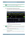


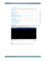
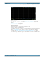
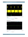
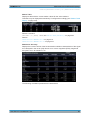
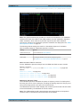
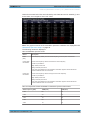
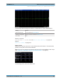
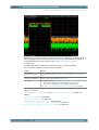
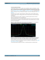
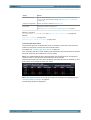

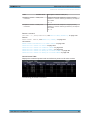

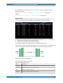
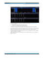
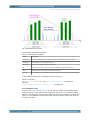
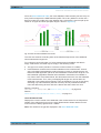
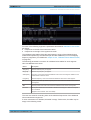
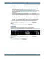
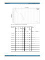
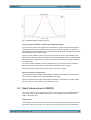
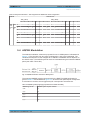
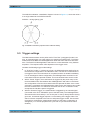
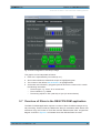
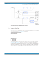
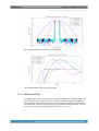
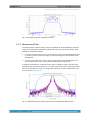
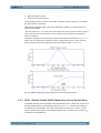
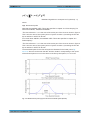
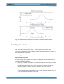
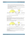
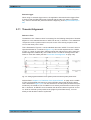
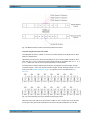
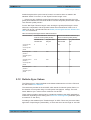
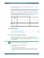

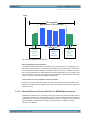

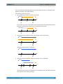
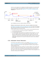
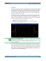

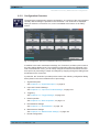

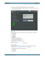
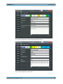
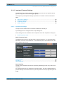
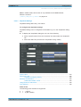
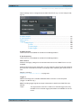
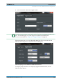
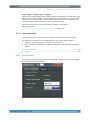
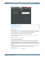
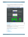
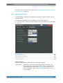
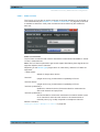
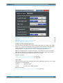
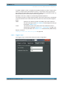
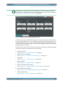
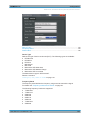
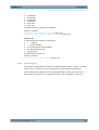
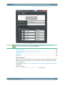
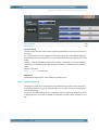
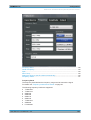

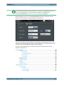
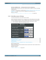

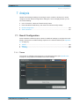
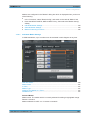
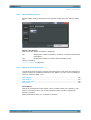
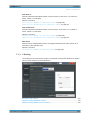
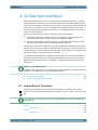
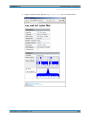


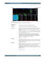


![[:SOURce]:BB:GSM[:FRAMe]](http://vs1.manualzilla.com/store/data/005841236_1-e838b09572e81e9a2469fdab27d799a4-150x150.png)