1
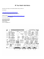
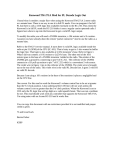
Arcom Communications
24035 NE Butteville Rd
Aurora, Oregon 97002
(503) 678-6182
[email protected]
RC-210 Repeater Controller
Assembly Manual
Hardware Version 3.0
Original Release Date September 13, 2004
Reproduction or translation of any part of this manual beyond that permitted by sections 107 or 108 of the 1976 United States Copyright Act (or its legal
successor) without the express written permission of Arcom Communications is unlawful as noted below. Requests for permission to copy or for further
information should be addressed to Arcom Communications. Except as noted above, permission is hereby granted for any non-profit group or individual to
reproduce any portion of this document provided that: the reproduction is not sold for profit; the intent of reproduction is to further disseminate information
on the RC-210 Repeater Controller kit; the reproduction is not used for advertising or otherwise promoting any specific commercial product other than the
RC-210; and full credit is given to Arcom Communications as the original source of information.
The information contained in the manual has been carefully checked for accuracy and is believed to be entirely reliable. However, no responsibility is
assumed for inaccuracies. Arcom Communications reserves the right to make changes in the RC-210 Repeater Controller kit to improve reliability, function
or design without obligation to purchasers of previous equipment. Arcom Communications does not assume any liability arising out of the application or
use of any product or circuit described herein; neither does it convey license under its patent rights or the rights of others.
Parts List
Integrated Circuits
Check off the part in the space provided as you locate
and verify against this list.
Resistors, 1/4 watt
Do not handle the IC's unnecessarily. Carefully remove
the IC tubes from the anti-static bag and check each one
against the parts. Then return the tubes with the ICs to the
bag.
(
(
(
(
(
(
(
(
(
(
(
(
(
(
(
(
(
) 15
)4
)3
)9
)3
)3
)3
) 14
) 3
10k ohm
22k ohm
47k ohm
100k ohm
470k ohm
110k ohm
33k ohm
470 ohm
47 ohm
(brown-black-orange-gold)
(red-red-orange-gold)
(yellow-violet-orange-gold)
(brown-black-yellow-gold)
(yellow-violet-yellow-gold)
(brown-brown-yellow-gold)
(orange-orange-orange-gold)
(yellow-violet-brown-gold)
(yellow-violet-black-gold)
)1
)1
)2
)1
)3
)1
)2
)2
Resistor Network
Sockets
( )1
(
(
(
(
(
470 ohm network (10 pin SIP)
Potentiometers
( )6
( )3
10k ohm (C103)
500k ohm (C504)
)3
)1
)1
)2
)5
ATMega128 (mounted on PCB)
ISD4003-04MP VoiceCorder
ULN2003A
MT8806 Crosspoint Switch
MT8870 DTMF Decoder
ST232 Level Translator
TL064 Operational Amp
74HC595 Shift Register
18-pin DIP Socket
24-pin DIP Socket
28-pin DIP Socket
14-pin DIP Socket
16-pin DIP Socket
Capacitors
Voltage Regulators
Capacitors may be marked in various ways. The typical
markings are given but may vary.
( )1
( )1
(
(
(
(
Connectors
) 23
)2
)2
)3
.1 uf
33pf
22pf
.0068uf
(104)
(330)
(220)
(682)
(
(
(
(
(
(
(
Electrolytic Capacitors
(
(
(
(
(
)4
)7
)4
)1
)2
1 uf
2.2 uf
22 uf
47 uf
10 uf
)4
) 22
)4
)4
)4
(
(
(
(
(
(
(
(
(
(
(
1N4001 Rectifier (might be 1N4002 or 1N4004)
1N4148 Silicon Diode
Red LED
Green LED
Yellow LED
Transistors
( )6
5.0 volt
3.3 volt
(LM340T5 TO-220 case)
(78L33, TO-92 case with piece of
tape on leads)
9-pin female right-angle PC mount
25-pin female right-angle PC mount
RJ45 modular jack
4 pin power female PCB power
4 pin power male plug
36 - pin single row header PC mount
10 pin dual row header PC mount
Misc.
Diodes
(
(
(
(
(
)3
)1
)3
)1
)1
)2
)1
(64 pin TQFP)
(28 pin DIP)
(16 pin DIP)
(24 pin DIP)
(18 pin DIP)
(16 pin DIP)
(14 pin DIP)
(16 pin DIP)
2N3904 NPN
2
)1
)1
)1
)1
)1
)1
)1
) 13
)1
)1
)1
Heatsink
4-39 screw and nut assembly
3.579 Mhz crystal
(3.57ECSV)
16 Mhz crystal
(160ECSV)
32768 Khz crystal
(small cylindrical)
10 uh choke (silver-black-black-red-silver)
Self-resetting Fuse (X030)
Push-on jumpers
PC Board (revision 2.8)
Assembly Manual
User Manual
Construction
Resistors
Resistors lie flat on the PC board and have a lead spacing
of 0.5". You may wish to use a lead former to preform the
resistor leads for the neatest appearance.
You are now ready to begin construction of the RC-210. Use a
temperature controlled, fine-tipped soldering iron and good
quality 60/40 rosin-core solder for construction. Follow standard
construction practices when building the unit.
Install the following resistors 10K (brown-black-orange-gold)
resistors:
You will also need small flush or semi-flush cutting pliers and
small-tipped needle nosed pliers. A magnifying glass may prove
useful for identifying the values of small parts.
(
(
(
(
(
Keep the tip of the soldering iron bright and clean, wiping it
frequently on a wet sponge or rag. Make solder joints carefully,
but swiftly. Prolonged heat on a PC board pad can be disastrous
and ruining this PC board can be expensive! Two or three
seconds should be enough time to apply heat to any joint. Follow
the order of construction, as they have been developed to make
installation of parts as easy as possible.
) R26, R27, R31
) R32,R38, R44
) R45, R51, R54
) R59, R60, R61
) R62, R63, R65
Install the following 47K (yellow-violet-orange-gold) resistors:
( ) R50, R52, R53
Install the following 22K (red-red-orange-gold) resistors:
The microprocessor (ATMega128) has already been soldered on
the board. Great care should be taken when assembling the RC210 to ensure there are no static discharge issues. The use of a
grounding wrist strap and grounded tip soldering iron is highly
recommended. (Note: DAMAGE DUE TO STATIC
DISCHARGE IS NOT COVERED UNDER WARRANTY)
( ) R34, R55, R67, R66
In the following 47 ohm (yellow-violet-black-gold)
( ) R29, R43, R49
IC Sockets
Install the following 470K (yellow-violet-yellow-gold) resistors:
Note: If any sockets are bent, carefully straighten them with a
pair of needle-nose pliers. When installing IC sockets, double
check to ensure that the socket is seated properly against the
board with the notch, beveled corner or "1" towards the
silkscreened reference (U1, IC2, etc). Be sure all IC socket pins
are showing on the solder side of the board. While making
certain the IC socket is tight against the PC board tack-solder
two diagonally opposite corners (such as pins 1 and 14 on a 14
pin socket). Then solder the remaining pins of that socket before
proceeding to the next one. If you find a socket is difficult to
install, remove it and check for bent pins.
( ) R10, R11, R12
Install the following IC sockets.
( ) R1, R2, R3, R4, R5, R9, R46, R47, R48
(
(
(
(
(
(
Install the following 470 ohm, (yellow-violet-brown-gold) resistors:
)
)
)
)
)
)
U6
U1, U2, U3
U4, U5
U7
IC2, IC3, IC4
IC5, IC6
Install the following 110K (brown-brown-yellow-gold)
( ) R28, R30, R36
Install the following 33K (orange-orange-orange-gold) resistors:
( ) R35, R40, R58
Install the following 100K (brown-black-yellow-gold) resistors:
24-pin
18-pin
14-pin
28-pin
16-pin
16-pin
( ) R6, R7, R8, R15, R16, R17, R18, R19
( ) R20, R21, R22, R23, R37, R57
(Resistors R13 and R14 are not included. See Hardware Manual
for details)
Now check all your work. All leads should be soldered with no
solder bridges or cold solder joints.
3
Potentiometers
Diodes
Carefully bend the three leads of each trim pot over 90 degrees, so
the leads face the back of the trim pot body. Then insert the leads
through the holes in the PC board, with the body closest to the
edge of the board, it is flush against the board. Then solder the
connections. (note: the pots should lay down against the board,
with the adjustment slot facing up)
Diodes are polarized devices, with the cathode end being banded.
Observe polarity when installing the following diodes.
10K ohm (C103)
( ) Port1 Disc, Port2 Disc, Port3 Disc
( ) Record, Play, Tone
( ) D11, D12, D13, D14, D15, D16, D17, D18, D20, D21
D22, D23, D24, D25, D26, D27, D33, D34, D35, D36,
D37, D38
500K ohm (C504)
LEDs
( ) D1, D2, D3, D5
Install the following 22 ea. 1N4148 diodes:
( ) P1 Tx, P2 Tx, P3 Tx
Install the LEDs 1/2" above the board to allow them to be bent over
later. Note that one side is flat; this is the cathode. Be sure the flat
side of the LED lines up with the flat side on the PC board.
Capacitors
(
(
(
(
(
(
The following capacitors are .1uf (104) and should be mounted as
close to the board as possible without stressing the leads.
( ) C1, C3, C5, C6, C9, C14, C15, C16, C17
( ) C19, C20, C22, C27, C31, C32, C35, C36
( ) C37, C38, C39, C45, C46, C47
Install the .0068 uf (682) capacitors
22pf (220)
33pf (330)
( ) Q1 - Q6
Electrolitic Capacitors
Connectors
These capacitors are polarized, so care should be taken to orient
them properly. Note that at the installation positions for these
capacitors, the PC board is marked with a plus (+). Note that the
capacitors have the minus (-) lead marked. Install accordingly.
Carefully install J1 taking care that no pins are bent over as you
insert them. Holding J1 flush against the PC board, solder two
opposite pins in order to the hold it in place. Then solder the
remaining pins, taking care to avoid solder bridges
The following are all 2.2uf.
Solder the two larger holes (one on each end) to the pads on the
PC board. Use lots of solder to make a mechanically secure
connection.
( ) C23, C26, C29, C34, C41, C44, C48
Install the remaining electrolytic capacitors:
) C11, C12, C13, C60
) C10
) C28, C33, C40, C42
) C4, C43
Red LED
Green LED
Yellow LED
Red Led
Green LED
Yellow LED
All transistors should be installed with the body not more than 1/4"
above the PC board. Match the body of the transistor with the
outline on the board and carefully bend the leads to match the hole
pattern on the PC board. All transistors are 2N3904
Install the following capacitors:
(
(
(
(
) P1Key, P2Key, P3Key
) P1Cos, P2Cos, P3Cos
) P1Ctcss, P2Ctcss, P3Ctcss
) P1Dtmf
) P2Dtmf
) P3Dtmf
Transistors
( ) C24, C25, C30
( ) C18, C21
( ) C7, C8
1N4001
( ) J3
1uf
47uf
22uf
10uf
25-pin female right-angle PC mount
Your RC-210 kit comes with 2 types of connectors for J2, J3 and J4
- either DB9 or RJ45 modular jacks. You must now decide which
you prefer to use. You may want to read the "Choosing Your
Connector" section at the end of this manual before proceeding
with this step.
( ) J6
( ) J7
( ) J8
4
RJ45 or DB9 female right angle PC mount
RJ45 or DB9 female right angle PC mount
RJ45 or DB9 female right angle PC mount
Install the Phoenix PC mount 4 pin jack at the location on the PC
board marked "Power". It should be installed so it fits inside the
outline marked on the PC board.
( ) Power
( ) RN1
Jumper Headers
4 pin (green)
Locate the 2 - 32 pin jumper header connectors. Carefully cut them
between pins (in the notches in the plastic) to create the following:
Voltage Regulators
(
(
(
(
(
(
IC1 is installed upright on the PC board with the metal tab lined up
with the dark line on the silkscreened outline on the PC board and
should be spaced 1/4 above the surface.
( ) IC1
78M05
(LM340T5)
Install the heatsink onto the metal tab of IC1 with the 4-40 hardware
provided. Then, cut off the excess length of the screw.
(
(
(
(
(
(
(
(
(
78L033 (CZ-3.3)
Inductor
L1 looks like a 1 watt resistor. Bend one lead over and install it
vertically on the board.
( )1
L1
2 pin
5 pin
2 pin
3 pin
3 pin
10 pin
3 pin
8 pin
6 pin
J4
Locate the push-on jumpers and slide them over pins 1 & 2 or 2 & 3
of the jumper headers depending on your COS polarity
requirements. Don't worry if you don't know which you need right
now, as you can easily change them later.
Install the following 2 crystals with the body 1/8 inch above the
surface of the PC board (Caution: Make sure you space the crystal
as stated, to avoid shorting traces on the PC board).
( ) JP7, JP8, JP10, JP11, JP12, JP13
(3.57ECSV)
(160ECSV)
Install push-on jumpers over pins 2 & 3 of JP2, JP3 and JP4. This
completes the audio path for the receiver amplifiers when the audio
delay board is not installed:
Crystal X1 looks differently from the other 2 crystals - it is a small,
cylindrical type with close-spaced leads. X1 should be mounted 1/4
above the PC board, then bent over so it lays flat against the board,
away from the Mega128.
( ) X1
) JP1
) JP2, JP3, JP4
) JP5, JP6, JP9
) JP7, JP8, JP10, JP11
) JP12, JP13
) J1
) J2
) J5
) J9
( )
3.579 Mhz crystal
16.00 Mhz crystal
10 pin
3 pin
5 pin
6 pin
8 pin
2 pin
Now install J5, the 10 pin dual row header
(silver-black-black-red-silver)
Crystals
( ) Y1
( ) Y2
)1
)7
)3
)1
)1
)4
Install the following pin headers you just created:
IC7 looks like a transistor. It should be installed just like the
transistors.
( ) IC7
470 ohm resistor network
( ) JP2, JP3, JP4
32768 Khz crystal
Install a push-on jumper on each of the 3 de-emphasis jumpers.
You can skip this step if you plan on using flat audio on your
repeater.
Fuse
The RC-210 uses a special, self-resetting fuse. It looks like a yellow
ceramic capacitor and is marked "X030"
( ) JP5, JP6, JP9
( ) F1
Install a push-on jumper on JP1. This enables the LED's (you can
remove it later if you wish to reduce current draw)
Fuse
Resistor Network
( ) JP1
The resistor network is a 10 pin single in-line package, colored
black. There is a white dot on one end, which indicates pin 1. Line
pin 1 up with "1" marking silkscreened on the PC board at RN1.
5
Check Your Work
Double check your work.
(
(
(
(
(
) All solder connections are bright and shiny.
) No solder bridges between IC socket pins.
) All components installed in their correct positions.
) Diodes, transistors, voltage regulators and electrolitic capacitors installed with their proper polarity.
) The pc board modifications are done correctly.
Congratulations! At this point your RC-210 is completely assembled except for the integrated circuits. These will be installed
after you run some voltage checks.
Checking Voltages
For these tests, you will need to connect power to the RC-210. It is suggested that you use a power supply with current limiting
"just in case".
Locate the green, 4 pin power plug and connect it as follows:
Pin 1
Pins 3 & 4
+11.5 to +15 Vdc
Ground (both of these pins MUST be connected to the power supply's negative leads)
Meter Plus Lead
(
(
(
(
(
) IC2, pin 16
) U6, pin 24
) U5, pin 4
) U5, pin 12
) U7, pin 27
Meter Minus Lead
Ground
Ground
U5, pin 11
U5, pin 11
U7, pin 12
Result
+5 ± 5%
Vcc ± 5% *
Vcc ± 5% *
1/2 Vcc ± 5%
3.3v ± 5%
* Vcc refers to the voltage supplied to the RC-210.
If you do not obtain the results above, carefully check the PC board for cold solder joints, bridges or unsoldered connections.
If all is well, remove power. You're now ready to install the socketed integrated circuits.
(
(
(
(
(
(
(
) U1, U2, U3
) IC2
) IC3, IC5
) IC4, IC6
) U4, U5
) U6
) U7
MT(CM) 8870
MAX232
74HC595
ULN2003A
TL064
MT8806
ISD4003-M4
Your RC-210 is now ready for installation and programming. Please consult the Operations Manual.
6
If You Need Assistance
We offer several ways you can obtain assistance with your RC-210:
Our Website:
http://www.ah6le.net/arcom/help.html
Our email list (it's a good idea for all RC-210 owners):
Send an email to: mailto:[email protected]
Or you may contact us directly at:
Arcom Communications
24035 NE Butteville Rd.
Aurora, Oregon 97002
(503) 678-6182
email: [email protected]
7