1
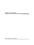
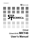
8-CHANNEL PROGRAMMABLE
PRESSURE INJECTOR
PM 8000
USER'S INSTRUCTION MANUAL
12345678901234567890123456789012
12345678901234567890123456789012
12345678901234567890123456789012
12345678901234567890123456789012
12345678901234567890123456789012
12345678901234567890123456789012
MDI
TABLE
INTRODUCTION
OF CONTENTS
--------------------------------------------------------------------- 1
1. INSTALLATION
----------------------------------------------------------------Safety Requirements ------------------------------------------------------System Setup
-------------------------------------------------------------Presetting Steps and Testing ----------------------------------------------Connections for Intracellular Injection System --------------------------Connections for Extracellular Microperfusion System -----------------
2
2
2
4
5
6
2. A CLOSER LOOK AT THE INJECTOR
Front Panel ----------------------------------------------------------------Rear Panel ------------------------------------------------------------------The Key Pad -------------------------------------------------------------------Optional Mouse -----------------------------------------------------------------
7
7
8
9
10
3. OPERATING AND PROGRAMMING -----------------------------------After Turning On the Power --------------------------------------------------Mode 1: Auto. Sequence --------------------------------------------------Mode 2: Pressure Monitor -------------------------------------------------Mode 3: Timer ---------------------------------------------------------------Mode 4: Counter ------------------------------------------------------------Mode 5: Action ---------------------------------------------------------------
11
11
11
14
15
16
17
4. PRINCIPLES AND TECHNIQUES FOR MICROINJECTION
Using The Balance Pressure ---------------------------------------------Microinjection for Different Tip Openings -----------------------------Manual Controlling Actions for a New User --------------------------Saving Gas -------------------------------------------------------------------
19
19
20
20
21
5. CAUTIONS AND TROUBLE SHOOTING -------------------------------- 22
6. SPECIFICATIONS ---------------------------------------------------------------- 23
7.
ACCESSORIES ------------------------------------------------------------------ 24
8.
WARRANTY ---------------------------------------------------------------------- 25
9. REMOTE PORT TECHNICAL REFERENCE ----------------------------- 26
MDI 12/02 S/W: PM008 V5.1
INTRODUCTION
.
.
.
.
.
KEY FEATURES:
Complete capabilities for microinjection and perfusion.
Up to eight inject/perfusion outputs, one hold cell output and one synchronized drain out channel.
Programmable and savable timers, counters and step sequences.
High speed channel action and flexible channel combination.
Convenient manual control or automatic sequential step cycle operation.
The PM 8000 Programmable 8-Channel Pressure Injector is designed for intracellular injection and
extracellular perfusion. It can be used for directly injecting different molecular agents, labelled dyes, genes,
RNA, DNA, proteins and cell organelles to a cell, or performing one of various combinations perfusion from
eight different agents and drugs to a cell or a group of cells. It is also a superior device for intracytoplasmic
sperm injection and cell electrophysiology. By combining an advanced microcontroller and precise pneumatic
components, the PM 8000 can simultaneously control eight injection micropipettes, one cell holding pipette
and one drain pipette.
The eight injection micropipettes can be controlled separately or combined together to perform actions such
as injection, capillary action balancing, suction or clear up. The cell holding pipette can produce an adjusted
vacuum to hold a cell or eject a pressure to push a cell or just clear the holding pipette itself. Also, the drain
pipette can produce an adjusted vacuum to drain out liquid precisely and synchronize with every
microperfusion. The PM8000 can deliver different agents and drugs from picolitters to continued perfusion.
The PM 8000 provides programmable timers and counters to deliver accurate timing and counting for
corresponding functions. The PM 8000 allows the user to program custom-designed action sequences. There
are 16 savable sequences with 32 programmable steps in each sequence. They can be used to perform and
repeat different sequential injections and perfusion cycles precisely. Also, the sequential cycles can be
automatically performed or triggered each step by manual. Even the interval time between steps is
programmable for automatic sequential cycle. All preset timers, counters and sequential steps are saved even
turn off the power. By pressing a button, even the pressure readings can be saved too. Therefore, the PM8000
is complete reproducible for an experiment at anytime.
There are individual regulators for adjustments of suction vacuum, cell holding vacuum, drain vacuum, inject
pressure and balance pressure. An LCD provides full information display such as pressure, vacuum, time,
sequence steps and actions. During pressure mode, all pressure readings are simultaneously
real-time displayed on the LCD screen so that the user can conveniently preset all the pressures without
switching the pressure measurement. Meanwhile, previous pressure reading can be recovered on the LCD
for further comparison.
An attached foot switch can control all preset step or be used as an injection trigger. An optional remote
keyboard and remote mouse give the user other convenient tools to control the whole operation or to interface
with a computer. The exceptional versatility and extremely precise control are the hallmark of the PM8000.
1
1. INSTALLATION
Safety Requirements:
Read this manual before installation of the instrument. This instrument is intended for using in laboratory
environment. This instrument needs correct power supply and correct gas source supply.
[1] The power supply should be the same voltage level as the specification on the back panel and must has
ground connection.
[2] The gas source supply should not be higher than 100 psi. Any very active, flammable or corrosive gas
can not be used as the input gas source. If using gas (nitrogen for example) other than compression air , fresh
air ventilation is required.
[3] Do not point output tubing, pipette to any person during operation. If not using the instrument, the power
supply and gas supply should be turned off.
[4] Do not disassemble the instrument box cover or service inside components.
System Setup:
[1] Gas Source and Tubing Connections: There is a GAS INPUT Connector on the PM8000 rear panel
(See REAR PANEL). Screw the 1/8" Hose Connector into the Pressure Input Connector and connect the other
end to a gas supply. Compressed air supply source is suitable for oxygen insensitive injection material. Inert
gas nitrogen is suitable for air sensitive material. A pressure of 60 - 100 psi is sufficient. An input pressure
of higher than 100 psi will damage the device. Any very active, flammable, corrosive or harmful gas is not
recommended for the input gas source. During the system normal operation, some source gas will be
bleeding from the system. If other gas instead of the compressed air is used as the input gas source,
sufficient environmental air ventilation should be considered. Turn off the gas source and system when
finishing an operation. There are ten gas output ports on the front panel (See FRONT PANEL). There are ten
inserts with hard wall tubbing which will prevent pressure be buffered in the tubing. Two of ten tubings are
2 mm OD which can be connected to single pipette holders for injection or cell holding. Eight of ten tubings
are 1.8 mm OD which can be connected to the Tygon tubing in the multipipette holder or to single pipette holders.
Optional vial tubing with connector is used to for microperfusion. Screw connectors to corresponding output
ports on the injector. Before connecting pipettes (before connecting vials for microperfusion ), use Clear (CLR)
and Clear Hold ( CLRH ) function to blow tubbing few times. After connecting pipette to pipette holder, make
sure no leakage at all connections of output port to tubbing, tubbing to vials, vials to pipette holder and pipette
holder to pipette. When using CLEAR or INJECT function, be sure the pipette or tubbing opening does not point
to a person.
[2] Two Different Systems Set Up : If the PM8000 is used for intracellular injection, refer the
CONNECTIONS FOR INTRACELLULAR INJECTION SYSTEM page for the system set up. Since small
quantity agent is needed for intracellular injection, only the injection pipettes are used to fill up agents, and
then inject to a cell. This set up is also referred for application of Intracytoplasmic Sperm Injection (ICSI).
If the PM8000 is used for extracellular microperfusion and multi-drug testing, refer the CONNECTIONS FOR
EXTRACELLULAR MICROPERFUSION SYSTEM page for the system set up. Vials or tubes should been
used in this system to hold agents, drugs and drain out liquid.
[3] Intracellular Injection: For intracellular injection, inject pipette is inserted to a cell from the side or
from above the cell. For suspended a cell, a second , larger pipette is used to hold the cell. This pipette's tip
is polished with a microforge. With its axis almost horizontal, it is moved to hold the cell with applied suction.
For intracellular injection, an inject pipette is inserted to a cell from the side or upper of the cell.
2
[4] Using Micropipettes: Microinjection technique also requires skills in making and using micropipettes. Micropipettes
ranging inside tip diameter from 0.10-5.0 um can be formed by a pipette puller. Change in inside tip diameter 10% will
change fluid conductance by 30%. Therefore, larger tip will deliver more material but easy damage to the cell. Smaller
tip need higher pressure to deliver material and easy to be clogged. A pipette with smaller tip can inject few picoliters,
the smaller tip the more precise control. For the tip smaller than 10 um, a direct balance pressure can be used. If the tip
larger than 20 um, a VENT function must be added to get less than 0.1 psi balance pressure (See PRINCIPLES AND
TECHNIQUES FOR MICROINJECTION).
[5] Foot Switch : A foot-switch or an optional handy switch can be connected to the FOOT SWITCH jack on the front
panel. A negative TTL control signal can be inputted to the TRIGGER INPUT BNC connector (top of the Foot Switch
Jack). It performs the same function as the AUTO key on the keyboard. An optional keyboard pad or a special mouse
can be connected to the REMOTE PORT for remote control purpose.
[6] Output BNCs : Besides the TRIGGER INPUT BNC, there are eight BNC connectors on the front panel which
produce TTL signals corresponding to eight injections from their output ports. The TTL outputs can be used to be recorded
or synchronize with the measurements responded from the microinjections or microperfusions.
[7] Special Mouse and Remote Key Pad (Optional): If a special optional mouse or a remote key pad is
used, insert the DB9 connector to the remote port of the unit. Place the mouse or the remote key pad near your
microscope. The mouse can control the Injection, Suction and Auto-sequence conveniently and quickly. The
remote key pad will perform the full function as the key pad on the unit.
[8] The AC Power : The power cord must be plugged into an AC outlet with an identical voltage as specified
on the rear panel. After turn on the power, the power indicating light must be on and the LCD display will display
the software version number.
3
Presetting Steps and Testing :
1) Check input pressure. 30-100 psi is workable, >102psi input pressure should be reduced. Let the buzzer
on during timer action. If you don't like 'beep' noise during action, turn it off ( See OPERATING ). Then press
the MODE key to next mode.
2) Check and select sequences, select and preset action steps. If you plan to perform auto-sequence perfusion
cycle, repeat injection cycle or use the foot switch to control action steps, programmed sequence steps are
necessary ( See OPERATING ). Then press the MODE key again;
3) Check and adjust pressures. Adjust pressure regulators while you monitor the pressure display. 20 psi for
injection, but do not try to adjust higher than 60 psi. 50 psi for fill, but do not try to adjust higher than 88 psi.
0.5 psi for balance is general initial pressure setting. If it is repeating last experiment, previous pressure reading
can be recovered. Update pressure reading memory is capable too ( See OPERATING ). Then press the MODE
key again;
4) Check and preset timers. Clear and set every timer for new sequence. 0.01 second for CLER, 0.3 second
for CLRH. 0.1 second for INJx and FILL are general initial setting. More than 1 second for clear inject pipette
(CLER) or for clear holding pipette (CLRH) is not recommended. Press the MODE key again;
5) Check and preset counters. Clear and set all count to 1 for new sequence. If volume is calibrated under
certain pressure and time, changing count will simply double volumes. Then press the MODE key again;
6) It is ready for actions now. Before connecting pipettes to pipette holders, be sure the pipette or tubbing
opening does not point to a person. Use Clear ( CLR ) and Clear Hold ( CLRH ) function to blow tubbing few
times. Then, connecting inject pipette to inject pipette holder, connect cell hold pipette to cell hold pipette
holder. Insert injection micropipette to some liquid (water), don’t forget press BALANCE key first to output
balance pressure to the injection pipette. Slowly increase the balance pressure to push the liquid out of the
pipette until all the liquid just out the pipette tip. The air should be stable in the pipette tip (See Fig. 1). If
increasing the balance pressure doesn’t push the liquid inside the pipette, check any leakage at all connections
of output port to tubbing, tubbing to pipette holder and pipette holder to pipette.
Now, the INJ key can be pressed to try an injection. A small air bubble can be injected during the short time
inject period. If the air is continue injected even the inject action indicator LED turns off, be sure the Balance
or the Vent function must be turned on before injection. For detail Balance and Vent function principle, see
USING THE BALANCE PRESSURE. If the injection is correct, then continue to try Vent , Fill, Clear, Clear
Hold, Hold cell functions to get used to the microinjector.
Increasing Balance Pressure
to push >>>
Capillary Action Balancing
Injecting
4
Fig. 1
Intracelluar Injection Connection :
PM8000 8-Channel Programmable Pressure Injector
30-100 psi Pressure
Source
Foot Switch
Special Remote
Mouse (Optional)
Hold Cell Pipette
Inject Pipette (1-7 barrel)
Cell Surgery Work Station Set Up :
PM8000 8-Channel Programmable Pressure Injector
Injection Pipette
Holding Pipette
Microscope and
Manipulators
Remote Key Pad or
Mouse (Optional)
Injection Pipette--
Foot Switch
---HoldCell Pipette
5
Connections for Extracelluar Microperfusion System:
PM8000 8-Channel Programmable Pressure Injector
ssure
i Pre
s
p
0
30-10
e
Sourc
7ba
rr
el
e
pett
n Pi
Drai
tte
Pipe
Cell
Hold
PP
Pip -7,
ett Pu
e lle
d
FS
Swi W , F
tch o o
t
l
ia
ec se
Sp ou
2, M
EUS te )
MO mo nal
Re ptio
(O
s
nal
sig
ing
s
tim
put
out
ion
ect
re
Inj
ssu
pre
nel
han
ion
8-c
ect
inj
nel
han
8-c
um
acu
v
ell
d c
l
o
H
um
acu
v
in
Dra
Drain out
liquid
Tested Cell
DT-800 Digital Recorder
6
e
ipett
ion P
t
c
e
j
In
Mi
He croe
ad le
st ct
ag ro
e
de
OP-1, Perfusion Vials for Testing Drugs or Agents (Optional)
Tes
tin
g
sig
Signal Conditioner or
nal
Patch Clamp Amplifier
2. A CLOSER LOOK AT THE INJECTOR
FRONT PANEL :
11
1
12
2
13
3
15
14
4
21
18
6
16
8
7
17
9
5
1
10
19
20
1. Rack Mounting Handles (optional)
13. DRAIN OUTPUT Port Connector
2. FILL Vacuum Control
Connect the tubbing insert. Drain vacuum for sucking liquid
pipette synchronizes every injection/perfusion and delivered
from this port.
Used to adjust and set supply pressure of FILL vacuum generator for INJ.OUTPUT ports.
3. BALANCE Pressure Control
Used to adjust and set BALANCE pressure for INJ.OUTPUT
ports.
4. INJECT Pressure Control
Used to adjust and set INJECT pressure for INJ.OUTPUT ports.
5. INJECT FOOT SWITCH Jack Port
Connect a foot-switch or other handy switch with a 3.5mm plug
into this jack port to perform the same function as pressing the
INJ key on the key board.
14. HOLD OUTPUT Port Connector
Connect the tubbing insert. Holding vacuum and clear pressure
for the holding pipette are delivered from this port.
15. Eight FILL/INJ. OUTPUT Port Connectors
Connect the tubbing inserts. The injection, balance, fill and clear
pressures for the injection/perfusion pipettes are delivered from
these ports.
16. Eight INJ.SYN. Signal Output BNCs
Produce negative synchronous TTL signal output during injection/perfusion corresponding to INJ. OUTPUT ports.
17. Remote Key Pad Port DB9 Connector
Connect an optional remote key pad or mouse to this
Displays real-time pressure, vacuum, time, count and total
port to perform convenient remote control. It is also an
information for programming.
interface port to a computer.
7. Action Indicating LEDs
Indicate CLEARing, CLEARing HOLD, HOLDing, BALANCing, 18. Retractable Tilt Stand
6. LCD Display Window
FILLing and INJECTing actions.
19. AUTO Function Foot Switch Jack Port
8. Control Keyboard
Used to program and control the microinjector.
9. Power Indicator and
10. Power Switch
Connect a foot-switch or other handy switch with a 3.5mm plug
into this jack port to perform the same function as pressing the
AUTO/STOP key on the key board.
Press the switch to turn power on, press again to trun power off.
The power indicator LED displays the power on or off.
20. AUTO Function Trigger Input BNC
Input a negative TTL signal to this BNC as a sequential
11. HOLD Cell Vacuum Control
step trigger . It performs the same function as AUTO key
Used to adjust and set HOLD vacuum for HOLD OUTPUT port. on the keyboard and the same function as the AUTO
foot switch.
12. Drain Vacuum Control
Used to adjust and set Drain vacuum output which will synchro- 21. Inject/Perfusion Port Open Indicators
nize with every injection.
The light on indicates corresponding working channel.
7
REAR PANEL :
1 AC POWER INPUT Connector
Connect the power supply cord and plug in an AC
power outlet same as the specified voltage.
2 Fuse Box
Replace with the same rating and size fuse only.
3 Gas Filter View Hole
Check filter bowl from this hole.
8
4 Filter Drain Hole
On the bottom panel as indicated. If accumulated
liquid is found in the filter bowl, press the drain valve
through the hole to drain out liquid.
5 GAS INPUT Port
Connect the 1/8" tubing connector for compressed
gas input.
The Key Pad
R
P
S
A
MODE
C
P
T
P OOFNF/
-ST
+ST
CH OFF
CH ON
R
P
0
1
s/ms STOP
VENT AUTO
-SQ
10
CH 8-1
-ST
0
CH OFF
+SQ
100 SP
CH 1-8
CLR RELB RELH CLRH
INJ BALN HOLD FILL
A
S
P
MODE
C
T
Press to change MODE : form SEQUENCE
to PRESSURE to TIMER to COUNT to
ACTION then going back to SEQUENCE ...
P ON
OFF
Press to turn off input pressure and halt the
mode, press again to recover mode and pressure.
s/ms
VENT
Press to select unit second or unit millisecond
during TIMER mode. Press to set or cancel a
VENT function in the SEQUENCE mode.
Press to open or close a vent hole in the inject
port during ACTION mode. An opening vent
hole will be display as ‘ V ‘ next to the ‘ACTION:’ on the LCD display. An opening vent
hole will provide a channel of atmosphere to the
injection port. Therefore, any balance, injection or suck pressure in the injection port will be
reduced or bypass by the vent hole. ( See TIPS
AND TECHNIQUES for detail application ).
STOP
AUTO
Press to set the last step and as a sequence
repeating step during SEQUENCE mode.
Press and release to trigger auto-sequence
steps or exit the sequence during AUTO SEQ
mode. Press to interrupt and stop any action
during action mode
+ST
1
CH ON
-SQ
10
CH 8-1
+SQ
100 SP
CH 1-8
CLR
Press to disable the buzzer during the power
on display. Press to display previous pressure
reading memory in the PRESSURE mode.
Press to select a step (down number) or turn
off selected channel for the SEQUENCE
mode. Press to reset number for TIME mode
and COUNT mode. Resetting timer is also
setting the timer to MANUAL control. Press to
turn off selected output channel during ACTION mode.
Press to enable the buzzer again during the
power on display. Press to select a step (up
number) or turn on selected channel for the
SEQUENCE mode. Press to add 1 to the
number for TIME mode and COUNT mode.
Press to turn on the selected channel output or
timer during ACTION mode.
Press to select a sequence (down number) or
select channel from 8 to 1 for the SEQUENCE
mode. Press to add 10 to the number for TIME
mode and COUNT mode. Press to select channel from 8 to 1 during ACTION mode.
Press to save pressure reading to the memory in
the PRESSURE mode. Press to select a sequence (up number) or select channel from 1 to
8 for the SEQUENCE mode. Press to add 100
to the number for TIME mode and COUNT
mode. Press to select channel from 1 to 8
during ACTION mode.
Press to select CLEAR function for SEQUENCE, TIME and COUNT modes. Press to
display input pressure from PRESSURE mode.
Press to generate the CLEAR function during
ACTION mode. This function will clear the
injection pipette, input source pressure is directly used and controlled by its timer and
counter. This function will help to avoid the
injection pipette from being clogged. CLEAR
channels are selectable.
9
RELB
RELH
CLRH
Press to select RELEASE BALANCE
function for SEQUENCE mode. Press to
turn off the Balance function during ACTION mode. This function will shut off the
injection port from the BALANCE pressure. Press again will open balance pressure for a pulse of 5 millisecond then
closing again.
Press to select RELEASE HOLD function
for SEQUENCE mode. Press to turn off the
Hold function during ACTION mode. This
function will turn off the hold cell vacuum
from cell hold port and release the held cell.
If the cell is still attaching the holding pipette
even after releasing holding vacuum, the
CLRH key can be press to push the cell
away. The pushing pressure can be adjusted
from the HOLD pressure regulator and controlled by its timer and counter. The CLEAR
HOLD function also can be used to clear the
holding pipette during ACTION mode. Press
to select CLEAR HOLD function for the
SEQUENCE, TIME and COUNT mode.
Press to display Hold pressure/vacuum from
PRESSURE mode.
INJ
BALN
HOLD
FILL
Press to select INJECT function for SEQUENCE, TIME and COUNT mode. During ACTION mode, press to generate an
injection which is controlled by selected
channel timer and counter, the adjustable
INJECT pressure is delivered to the injection pipette. The injecting channels are
selectable. The Drain function is also synchronized with every injection. Adjusting
the Drain vacuum will change the drain
speed.
Press to select BALANCE function for
SEQUENCE mode. During ACTION mode,
press to deliver an adjustable BALANCE
pressure to the injection pipette to balance
capillary action and cancel buffering pressure.
Press to select HOLD function for SEQUENCE mode. During ACTION mode,
press to generate an adjustable hold cell
vacuum to the holding pipette to grasp a cell
on the polished tip.
Press to select FILL function for SEQUENCE, TIME and COUNT mode. During ACTION mode, press to generate a
suction vacuum, which is controlled by its
timer and counter. The FILL channels are
selectable. The adjustable suction vacuum
is delivered to FILL the injection pipette.
MOUSE-2 Remote Control Mouse (optional)
An optional mouse can be plugged into the digital
port for remote and manual control. If use INJECT
or FILL switches of the mouse for manual control,
first set the Inject time and Fill time to MANUAL
and set the Auto time to CONTINUE for more
convenient manual timing control.
10
INJECT Switch
AUTO Switch
FILL Switch
3. OPERATING AND PROGRAMMING
After turning on the power ...
After turning on the PM8000 power switch, the LED power indicator must be on and the LCD displays the
software version number. The following message will be display to monitor input pressure:
Press to turn off the buzzer.
INPUT/CLEAR
PRESSURE
100 psi
BUZZER ON
R
P
-ST
0
CH OFF
> INPUT/CLEAR
PRESSURE
100 psi
BUZZER OFF
+ST
<
1
CH ON
Press to turn on the buzzer.
If input pressure is less than 30 psi., adjust or change the input gas source to meet the requirement. 100 psi. is
the maximum. The input pressure also is the CLEAR pressure. BUZZER ON indicates that the buzzer will beep
when one of the CLEAR, CLEAR HOLD, INJECT or FILL function is activated. The user can turn the buzzer
off by pressing the key 0, or on again by pressing key 1.
There are five MODEs to operate and program the PM2000B. Press MODE key on the keyboard to select one
of five MODEs as the following : PROGRAMMING SEQUENCE ----- DISPLAYING PRESSURE -----SET
TIMER ----- SET COUNTER ----- ACTION ----- back to first mode.
Keys for power on:
R
P
-ST
0
CH OFF
press
to next
mode
MODE
MODE 1 :
Press to disable
the buzzer.
+ST
1
CH ON
Press to enable
the buzzer.
A
S
MODE
C
P
Press to mode 1.
T
PROGRAMMING SEQUENCES
After pressing the MODE key one time, the PM8000 enters MODE 1, the Automatic Action Sequence
mode. This mode lets the user review and select one of 16 sequences or preset action for each of 32 steps.
In the action mode, these sequences will let the user activate functions without pressing different keys and
repeat the action sequence cycle conveniently. Besides 32 action steps, there are eight timers, seven
counters and pressure reading memory in each sequence. The pressure reading is on the next mode. The
programming of timers and counters will be described in third and fourth modes.
Press to add sequence number.
V
SEQUENCE 1:
S 1 : CLEAR
S 2 : CLR.HOLD
S 3 : FIL1234
+SQ
S
100 P
CH 1-8
<
-SQ
10
CH 8-1
> SEQUENCE 2:
S 1 : INJ1
S 2 : INJ12
S 3 : INJ123
Press to reduce sequence number.
11
Presetting an action on each step will let a user activate automatic sequential actions or trigger actions step
by step with just pressing foot switch or pressing AUTO key in an action mode. If a user plans to control actions
by manually pressing individual action key (No automatic sequence actions), presetting action step is
unnecessary. If a user wants to control an action time manually, the action timer can be set to MANUAL(0) (will
be described on time mode). Then in the action mode, the user can press and hold the action key to act until
releasing the key to stop.
When the PM8000 is turned on the power, the unit will recover the previous sequence which performed just
before the unit power off. If the user wants to edit or use other sequence setting, key 100 (+SQ) can be pressed
to go up the sequence number or key 10 (-SQ) to go down the sequence number. Changing a sequence will not
only give the user a different action steps, but also will give the user different pressure reading memory, different
setting timers and counters which will be reflected on following modes. In other words, the PM8000 can store
up to 16 complete different settings which include 16 sets of 32 action steps, 16 pressure readings, 16 sets
of timers and 16 sets of counters.
There are up to 32 programmable steps in a sequential cycle. The LCD displays the first 3 steps in the beginning of
this mode. The cursor blinks on third step row which means the being edited step row.
Press key 0 (-ST) to go down the edited step number.
Press key 1 (+ST) to go up the edited step number.
Press key 10 (-SQ) to go down the sequence number.
Press key 100 (+SQ) to go up the sequence number.
Press one of the CLR, RELB, RELH, CLRH, INJ, BALN, HOLD, FILL and VENT(s/ms) keys to preset
corresponding function in the current edited step. Press the same key as the step setting function will cancel
the setting of the step. Pressing INJ, FILL or CLR key first time will display ' INJ??', 'FILL?' or 'CLEA?' , which
ask you select output channel number. Press CH8-1 or CH1-8, OUT2 to select output channel then press CH
ON or CH OFF to turn on or off the channel. For injection channels, the first selected channel will be used as
the control timer channel. Continue the selection until the combination fits you need. Then pressing the same
function key will back the cursor to step selection. In the step selection, pressing the same key again will cancel
the function. In the step selection, the CHOFF and CHON keys will be the -ST and +ST keys to down and up
the steps. Since there are 8 timers for injection, the first selected output channel will be the control timer for
any inject combination during setting the 'INJ??' step. The first number after the INJ indicates the control timer
channel only (not the opened channel). The control timer channel can control the combination without the control
channel open by pressing the control channel first, and then press the channel off after finishing at least another
channel is set. On the other hand, the FILL and CLEAR are control by their timer only, they are not controlled
by the 4 injection channel timers . When finishing the output port selection, pressing the INJ, FIL or CLR key
again will back to next step selection. Pressing the VENT(s/ms) key will preset the VENT function step. First
VENT step will open the vent hole, then the second VENT step will close the vent hole (toggle key operating).
Press key AUTO to preset return function in the current step. This function will cause the first step to become the
next step and repeat the sequential step cycle. Therefore, the step AUTO must be the last step of the sequence
if automatic recycle the sequence is needed. See the following page for detail sequence setting diagram.
12
SEQUENCE 1:
S 1 : CLEA12345678
S 2 : CLR.HOLD
S 3 : FIL1
Press to
injection.
Press to
down step.
R
P
-ST
0
CH OFF
SEQUENCE 1:
S 1 : CLEA12345678
> S 2 : CLR.HOLD
S 3 : FIL1
Press to cancel
same function.
INJ
V
SEQUENCE 1:
S 1 : CLEA12345678
S 2 : CLR.HOLD
S 3 : INJ??
Press to select port
1to port 8, the first
selected channel will
be dominant timer.
+SQ
100
CH 1-8
V
SEQUENCE 1:
S 1 : CLEAR
S 2 : CLR.HOLD
S 3 : INJ?1
Press to enter (turn on)
the selected
channel.
1
CH ON
MODE
1
CH ON
s/ms
VENT
V
SEQUENCE 1:
S 1 : CLEA12345678
S 2 : CLR.HOLD
S 3 : VENT
Press
to
open a vent.
CLRH
>
Press to select
second port.
SEQUENCE 1:
S 1 : CLEAR
S 2 : CLR.HOLD
S 3 : INJ111
Controlled by
INJ1 timer
Next mode... <
SEQUENCE 1:
S 1 : CLEA12345678
>
S 2 : CLR.HOLD
S 3 : FIL1
+ST
V
SEQUENCE 1:
S 1 : CLEA12345678
S2:
S 3 : FIL1
+ST
Press to
next mode.
Press to
up step.
+SQ
S
100 P
CH 1-8
SEQUENCE 1:
> S 1 : CLEA12345678
S 2 : CLR.HOLD
S 3 : INJ112
Selecting
channel
Press to turn
on selected
port.
Channel 1 on
SEQUENCE:
S 1 : CLEA12345678
S 2 : CLR.HOLD
S 3 : INJ112
Press to finish the
injection step.
<
INJ
+ST
1
CH ON
V
SEQUENCE 1:
S 1 : CLEA12345678
S 2 : CLR.HOLD
S 3 : INJ1122
Keys for Mode 1 :
s/ms
CLR RELB RELH CLRH INJ BALN HOLD FILL VENT
AUTO
Press to preset a function on the step, press the same key will cancel the function. To select action channel for CLEAR,
FILL or INJECT, press the function keys then press CH8-1, CH1-8 to select channel combination, then press CHOFF
or CHON to turn off/on the channel then press the same function key to turn the cursor to step selection position.
+SQ
-SQ
Press to select a sequence when cursor blinks in step position. Press to select action channel when cursor
10 100 SP
CH 8-1
CH 1-8 blinks on channel position.
Press to select a step when cursor blinks in step position. Press to turn off or on the selected channel when
cursor blinks on the channel position.
S
A
P Press to
ON/ Press to turn off input pressure and
P OFF halt the mode, press again to recover. CMODET mode 2.
-ST
+ST
CH OFF
CH ON
R
P
0
1
13
MODE 2
PRESSURE MONITOR
Press to enter mode 2.
By pressing the MODE key second time, the PM2000 enters MODE 2 from
MODE 1. The fill vacuum generator pressure, injection pressure, balance
pressure and holding vacuum are simultaneously displayed on the LCD.
FILL - Monitors the supply pressure for the fill vacuum generator, real-time
displays the change while adjusting Fill supply pressure control. Refer
to the Fill Vacuum / Flow Characteristics for relation ship of vacuum
and pressure. The Fill supply pressure also is the Drain vacuum
supply pressure. The maximum Drain supply pressure is 50 psi.
Higher than 50 psi will decrease the drain vacuum.
INJ - Monitors the injection pressure, real-time displays the change while
adjusting the Inject pressure control.
BALN - Monitors the balance pressure, real-time displays the change while
adjusting the Balance pressure control.
HOLD - Monitors the holding vacuum, real-time displays the change while
adjust the Hold vacuum control. The actual vacuum will be displayed
while the holding action is on. The actual vacuum will be more
negative than the displayed number when the displayed number is
larger than 3 (-iH2O). If the holding action is off, the displayed
vacuum will be more negative than the actual vacuum.
MODE
V
P:FILL 60.0
psi
INJ 20.5 psi
BALN 2.5
psi
HOLD 3.2 -iH2O
Press to display previous
saved pressure readings.
R
P
-ST
0
CH OFF
V
P:FILL 60.0 M 50.0
INJ 20.5 M 10.0
BALN 2.5 M 1.0
HOLD 3.2 M 5.0
Press to save
current readings.
Pressing the 0 (-ST) key, the previous saved pressure readings will be
displayed on the right side of the monitored pressure.
+SQ
S
100 P
CH 1-8
With the comparison of previous memory reading, the user can adjust the
pressure controls to the same number as before to ensure the identical pressure
condition. If a user want to up date the present pressure setting to the memory,
just simply pressing the 100 (+SQ) key, all current pressure readings will be
stored into the current sequence memory.
V
P:FILL 60.0 M 60.0
INJ 20.5 M 20.5
BALN 2.5 M 2.5
HOLD 3.2 M 3.2
Pressing CLR or CLRH keys while in the MODE 2, the LCD will display
INPUT/CLEAR pressure. Pressing one of the FILL, INJ, BALN and HOLD
keys, the LCD will back to four pressure monitor above.
Press to next mode.
MODE
V
Next mode ...
Press to display
input pressure.
CLR
Press to display
4 pressures.
P:FILL 60.0
psi
INJ 20.5 psi
BALN 2.5
psi
HOLD 3.2 -iH2O
<
V
INPUT/CLEAR
PRESSURE:
100 psi
INJ
Keys for Mode 2 :
Press to Review previous
CH OFF Pressure reading memory.
Press to display inCLR CLRH
put/clear pressure.
R
P
14
-ST
0
+SQ
S
100 P
CH 1-8
Press to Store present Pressure reading
to the memory.
ON/ Press to turn off input pressure and
P OFF halt the mode, press again to recover.
A
S
MODE
C
P
T
Press to mode 3.
MODE 3
TIMER
Press to enter timer mode.
By pressing the MODE key third time, the PM8000 enters MODE 3 from
MODE 2. The LCD displays first four INJ timers. Press INJ key to select
INJ#. Each timer will determine one of four ports injection time.
MODE
V
T: INJ1
INJ2
INJ3
INJ4
Press s/ms (VENT) key to select unit second or unit 10 millisecond. Press key
0 to reset the timer (The action time will be controlled by pressing the action key
manually), which displays as 'MANUAL 0s(m)'. Press key 1 to add 1 into the
timer. Press key 10 to add 10 into the timer. Press key 100 to add 100 into the
timer. The maximum time setting for each timer is 327.66 seconds. More than
327.66 seconds setting will turn the timer to be continue (The action time will be
interrupted by pressing the STOP key only), which displays as
'CONTINUEs(m)'.
Press to select time unit.
s/ms
VENT
V
After setting all INJ timers, pressing any one of FILL, CLER, CLRH or AUTO
key will turn the LCD to display four of FILL, CLER, CLRH and AUTO timers.
The AUTO timer will determine the time interval between actions during
automatic sequence cycle. Setting AUTO timer to CONTINUE will let a user
trigger each step action by manual pressing foot switch or pressing AUTO key
during ACTION mode.
T: INJ1
INJ2
INJ3
INJ4
T: FILL
0100msc
CLER
0010msc
CLRH MANUAL0ms<
AUTO
0100msc
R
P
-ST
0
OUT1
0.95sec
0.10sec
0.10sec
0.10sec
Press to reset a timer.
For each new sequence, do not set CLER and CLRH timers longer than 1
second for general usage.
Press to
reset.
0950msc
0100msc
0100msc
0100msc
R
P
-ST
0
CH OFF
T: INJ1
INJ2
INJ3
INJ4
T: FILL CONTINUEs
CLER
0010msc
CLRH
0100msc
AUTO
0100msc
V
MANUAL 0s
0.10sec
0.10sec
0.10sec
Press 4 times to maximum time.
-SQ
10
OUT3
T: FILL
CLER
CLRH
AUTO
Press to
next mode.
MODE
V
Next mode ...
Press to
add 10.
0100msc
0010msc
0010msc
0100msc
s/ms
VENT
Press to change
time unit.
+SQ
Press to
other 4
timers.
T: FILL CONTINUEs
CLER
0.01sec
< CLRH
CLRH
0.10sec
AUTO
0.10sec
S
100 P
CH 1-8
V
T: INJ1 CONTINUEs
INJ2
0.10sec
INJ3
0.10sec
INJ4
0.10sec
Keys for Mode 3 :
Press to select one of eight action timers (Press INJ to select
INJ FILL CLR CLRH AUTO eight injection timers, press one of FILL, CLR, CLRH and
AUTO to switch their timer display).
+SQ Press to add number
-SQ
-ST
+ST
s/ms Press to select unit second
R
S
P 0
1
10 100 P
VENT or unit millisecond.
CH OFF CH ON
CH 8-1
CH 1-8 on the timer.
P ON/
OFF
Press to turn off input pressure and
halt the mode, press again to recover.
A
S
MODE
C
P
Press to mode 4.
T
15
MODE
4
Press to enter counter mode.
COUNTER
MODE
By pressing the MODE key fourth time, the PM8000 enters MODE 4 from
MODE 3. The LCD displays FILL, CLER and CLRH counters. Press 0 key
to reset each timer for a new sequence, then press 1 key to initial each counter.
Press one of the CLER, CLRH and FILL keys to move cursor to CLER , CLRH
and FILL counters. Press INJ key to display eight INJ counters. Press INJ key
to move cursor to different INJ channel.
The counter will determine how many times the action occurred in each action
trigger (manual and sequential). If the user calibrates the unit delivery for
injection or suction under certain pressure and time, the counter can be simply
used to add up the volume of delivery.
V
COUNT:
FILL
CLER
CLRH
255
255
255
Press to reset a new counter.
R
P
0
CH OFF
V
COUNT:
FILL
CLER
CLRH
Press key 0 to reset the counter.
Press key 1 to add 1 into the counter.
Press key 10 to add 10 into the counter.
Press key 100 to add 100 into the counter.
The maximum count setting for each counter is 255.
-ST
0
255
255
Press to initial 1 to a counter.
+ST
1
Press to CLEAR counter.
COUNT:
FILL
CLER
CLRH
<
1
255
255
CLR
CH ON
V
COUNT:
FILL
CLER
CLRH
1
255
255
Press to display INJ counters.
INJ
Press to next INJ counter.
Press to next
mode
Next mode ... <
INJ1
INJ2
INJ3
INJ4
MODE
1
1
1
1
INJ5
INJ6
INJ7
INJ8
1
1
1
1
<
INJ
INJ1
INJ2
INJ3
INJ4
V
1
1
1
1
Keys for Mode 4 :
INJ C LR C
LRH
+SQ
-ST
+ST
CH OFF
CH ON
P ON/
OFF
Press to turn off input pressure and
halt the mode, press again to recover.
R
P
16
-SQ
Press to select one of seven action counts (Press INJ to select eight
FILL injection counts, press one of FILL, CLR and CLRH to switch their
count display).
0
1
10
CH 8-1
S
100 P Press to add number on the counter.
CH 1-8
A
S
MODE
C
P
T
Press to mode 5.
INJ5
INJ6
INJ7
INJ8
1
1
1
1
MODE 5
ACTION
Press to action mode.
Pressing the MODE key fifth time, the PM8000 enters the last MODE 5 from
MODE 4. The message 'ACTION' will be displayed on the LCD and the input
pressure is monitored on the right side of the message.
In this mode, if a user want to manually control actions, press CH8-1 or CH18 then press CHOFF or CHON to turn on channels which will be used, then
press one of the CLR, RELB, RELH, CLRH, INJ, BALN, HOLD, FILL and
VENT (s/ms) keys to generate different action on the selected port(s). Since
there are eight timers for the injection, the control injection timer will be
selected by the first pressing open channel after all channels are closed. A 'T'
before 'CH' ( Timer Channel)indicates this channel timer takes control for
whatever the injection combination will be. The CLR, CLRH, and FILL
functions are determined by the their own presetting timer independent of
opened channel combinations. They also have their counter and control
pressure. During their actions, if the preset timer is longer than 0.5 second,
the action time counting will be displayed on right side of the function name.
The operating pressure is real-time displayed instead of input pressure.
Therefore, instant action pressure adjustment is possible during action mode.
If the preset timer is less than 0.5 second, the action time and action pressure
will be displayed after the action. To interrupt (stop) the acting action, press
the STOP/AUTO key. The interrupting time will be displayed next to the
action name.
Connect a drain pipette to the drain port when microperfusion is needed. The
suction from the drain port synchronizes injection on any inject port. Adjust drain
vacuum regulator to match the flow rate of perfusion. The microperfusion can be
made so precise that it does not lose a drop.
The HOLD, RELH, BALN and RELB functions are manual control and
pressure adjustable only. There are no timer countdown display for these
actions. After selecting output port(s), press BALN key to turn on balance
pressure is necessary for fill and injection. Insert the inject pipette(s) to the
solution. Adjust the balance pressure to let the out going bubbles just stop from
pipette tip. Keep the balance pressure on during actions. For detail principle of
balance pressure, see the page of USING THE BALANCE PRESSURE.
MODE
V
ACTION : <- 60 psi
Press to turn on the first
output channel and timer.
-SQ
+SQ
+ST
CH 8-1
CH 1-8
CH ON
10 or 100 then
1
V
ACTION : <- 40 psi
TCH1 ON
Controlled by this This channel
port opened.
channel timer.
Press to turn on other
output channel.
-SQ
+SQ
+ST
CH 8-1
CH 1-8
CH ON
10 or 100 then
1
V
ACTION : <- 40 psi
CH2 ON
Not controlled by This channel
this channel timer. port opened.
Press to trigger Fill function.
FILL
Pressing the VENT (s/ms) key will open a vent hole inside the injection port
to atmosphere, pressing the VENT (s/ms) key again will close the hole. A
'V' displayed after the 'ACTION: 'on the LCD indicates the vent hole is
opened and a '<-' indicates the vent hole is closed. When a VENT is on,
part of the pressure inside inject pipette will be bypassed to atmosphere.
Vent opened
Press to open or
close a vent hole.
ACTION : V 60 psi
V
ACTION : <- 40 psi
FILL
1.50sec
Vent closed
ACTION : <- 60 psi
<
s/ms
VENT
>
17
Automatic Sequence with Interval=0(MANUAL)
STEP3 time
STEP2 time
STEP1 time
interval time <1ms
>
stop
interval time <1ms
Press
Press
Automatic Sequence with Interval Time
AUTO
AUTO
v
v INJ1 time
INJ3 time
INJ2 time
interval time
>
interval time
interval time
A
UTO
or
foot switch
V
ACTION : <- 60 psi
AUTO-SEQUENCE 1
1 OF 16 STEPS
Press to interrupt the sequence.
A
UTO
or
foot switch
V
ACTION : <- 30 psi
INJECT
2.00sec
AUTO-SEQUENCE 1
2 OF 16 STEPS
...
Press
AUTO
v
Press
A-STOP
v
Press to trigger the auto-sequence.
...
If Automatic or Manual Step Sequence Action is required, pressing the
AUTO key (or trigger signal to AUTO BNC, or step on foot switch which
insert into the AUTO connector) first time will display the sequence number
and total steps. Pressing the AUTO key second time will trigger the
sequence actions. The actions will be depended on the sequence setting. If
the INTERVAL time was set to 0(MANUAL), the fastest switching steps
(<1ms) will be. If the INTERVAL time was set to CONTINUE, the user had
to manually trigger each step by pressing (or stepping, or pulsing) the AUTO
switch.
To halt an automatic sequencing action or interrupt any action, press the
STOP/ AUTO key will stop the action immediately and the interrupting time
will be displayed next to the action name.
Press to retrigger the
sequence again.
stop
A UTO/
STOP
Manual Trigger Sequence, IntervalL = CONTINUE
Press
AUTO
v
STEP1 time
Press
AUTO
v
STEP2 time
Press
AUTO
v
Press
AUTO
v
STEP3 time
>
After interrupting the sequence, any action key can be pressed to insert a
function between two sequential steps. The PM8000 will back to the
sequence by pressing AUTO key or foot switch again. If an action is one of
the CLR, CLRH, INJ and FILL functions and timer setting is longer than 1
second, their counting timer will be displayed on right side of the function
name.
Pressing the MODE key one more time, the program will jump back to MODE
1.
or
foot switch
V
ACTION : <- 30 psi
INJECT
0.73sec
AUTO-SEQUENCE 1
13 OF 16 STEPS
press
MODE
V
Back to first mode
Keys for Mode 5 :
STOP Press to trigger auto-sequence
AUTO steps or interrupt a manual action.
R
P
-ST
0
CH OFF
+ST
1
CH ON
-SQ
10
CH 8-1
+SQ
S
100 P
CH 1-8
Press to select and trun
on/off injection channels.
s/ms Press one of function keys to
CLR RELB R
C
INJ B A L H O FILL VENT
generate an action.
LD
ELH LRH
N
S
A
Press
to
turn
off
input
pressure
and
P
MODE
P ON/
Press back to mode 1.
C
T
OFF halt the mode, press again to recover.
18
4. PRINCIPLES AND TECHNIQUES FOR MICROINJECTION
USING THE BALANCE PRESSURE
There are two purposes when a balance pressure is applied to the injection pipette. The first purpose is to restrict
the inject pressure or suction vacuum to be buffered in the pipette after an action. . Another purpose is to compensate
the suction caused by a micropipette capillary action. The following two characteristics compare the injection output
with / without balance pressure:
INJECTING
PRESSURE
INJECTING
PRESSURE
PRESET
PRESSURE
PRESET
PRESSURE
BALANCE
PRESSURE
BALANCE
PRESSURE
TIME
INJECTION
PRESET TIME
TIME
INJECTION
PRESET TIME
Injection with balance pressure will
turn off at the correct timing.
PRESSURE
BUFFERED TIME
Injection without balance pressure will continue inject
for some time even the injection valve is turned off.
The smaller ID of a pipette, the stronger capillary action it has. There are different capillary action forces inside
a pulled micropipette because there are different IDs from the tip to unpulled portion of a pipette. Therefore,
to keep liquid inside a pipette closer to the tip, higher balance pressure must be applied. Other factors to effect
the applied balance pressure are the surface tension of the liquid and the depth of tip inserting in the liquid.
An example of balance pressure applied to a pulled pipette as following :
Balance Pressure:
0.06 psi
0.06 psi 0.35 psi
1 psi
1.5 psi
3 psi
4.5 psi
0.58 mm I.D.
1 mm O.D. pipette
10 um tip opening
The liquid boundary
The pulled pipette can be precisely controlled to suck or inject by the microinjector. The following
characteristic chart shows the princeple of suction or ejection corresponding to different valve action for the
pipette above:
<
Suction from the pipette tip
> < Ejection from the pipette tip >
Turn on INJECT valve
Turn on FILL
valve
Turn on BALANCE and VENT valves
Turn on BALANCE valve only
Turn on VENT valve only
Output port
pressure : -20" Hg
0 0.2 psi 4.5 psi
Adjustable range of
ejection or suction :
Capillary action balance point at
10um tip opening
10 psi
^
20 psi
SUCTION AND EJECTION CHARACTERISTIC OF A PIPETTE TIP
19
MICROINJECTION FOR DIFFERENT TIP OPENINGS
There are different control methods when using pipettes with different tip opening size. The following Table
1 measures balance pressures with different tip opening or taper I.D. in water, from 0.06 psi to 50 psi.
TAPER I.D. or
TIPOPENING
BALANCE
PRESSURE
Unpulled(0.6mm)
0.06 psi
180 um
0.18 psi
100 um
Tip
section 10 um
0.35 psi
COMMENT
Vent should be turned on as well as setting
balance to minimum
Tip
Unpulled
section
Taper
section
Adjusting balance manually will back and forward the solution inside the taper.
4.5 psi
2.5-1 um
10 - 25 psi
< 1 um
26 - 50 psi
Good for quantitative injection.
For very sensitive agent test or injection.
TABLE 1
The relationship between microinjector controlling method and the size of tip opening is discussed as the
following:
Larger Tip (>200 um) or Unpulled Section of a Pipette: There is very rare to need a pipette opening larger than
200 um, because the injected volume is big even with the small injection pressure and is hardly controlled precisely.
The balance pressure is very low, usually <0.1 psi, even turning the Balance pressure to minimum is still too high.
In this case, the Vent function must be pressed on. The Vent function actually opens a vent hole inside the injection
channel to bypass some balance pressure and cause the balance pressure can be adjusted to lower than 0.1 psi.
However, with larger tip, the pipette is easily filled up just by its capillary action. Always turn on balance first, the
liquid can be sucked by pressing on Fill and liquid can be pushed out by pressing on the Inject. If the liquid is pushed
out again after filling, the balance is too high. If the liquid is sucked back again after the injection, the balance is too
low. Usually, because the injection pushes the liquid all the way from unpulled section to out of tip of the pipette, the
pressure balancing the unpulled section is too low to keep the balance on the tip, then the liquid will be sucked back.
Therefore, perform Fill function or capillary action to suck liquid higher than the unpulled section, then set correct
balance to keep liquid stable inside the unpulled section. Now the liquid can be freely sucked in or pushed out only
in the unpulled section of the pipette by press Fill or Inject. If the small amount liquid can only be played around inside
the taper and tip section, turning the balance control knob manually only will move the liquid back and forward from
the tip.
Medium Tip (10-100 um): The suction and injection principles are the same as the larger tip pipette, except the
balance pressure at the tip is higher (4.5 -0.35 psi). This balance range is covered by the Balance adjustment without
turn on the Vent. However, the balance pressure for the unpulled section is still very low (<0.1psi), the Vent should
be turned on too. The Inject and Fill functions still work only for the liquid inside the unpulled section. But playing
the liquid inside the taper and tip section can be performed with turning Balance knob without turning on the Vent
Unpulled section
Taper section
Holding Pipette
Media drop with target cell
20
Tip section
1234567
1234567
1234567
Injection Pipette
123456
123456
123456
123456
Solution or agent drop to be sucked then
injected
function. For instance, in the application of Intracytoplasmic Sperm Injection (ICSI), with a long and fine pipette
taper and tip ( 2-10 um I.D.) and just turning the balance pressure adjustment knob, a sperm can be picked up
and ejected out of the tip precisely. The pipette with 20-50 um I.D. opening can also be used to produce a holding
pipette. To form a holding pipette, the pipette tip is polished by a microforge until 10-20 um I.D. and 70-120
um O.D.for the tip, then it is bent to about 30-40 degree angle by a microforge or the flame of a small burner.
Small Tip (1-2.5 um): This is a very practical pipette tip size for the microinjection. Since the tip is small, the tip
fiction is high and become the major factor to effect the liquid in and out of the tip. If the tip is emerged to the liquid,
the liquid sucked in by capillary action is not as high as the pipette with bigger tip opening. To see the first air bubble
producing on the tip (balance pressure at the tip), the pressure must be added to around 8-12 psi - excess some
balance adjustment range. However, since the tip fiction is high, the balance pressure can be just set about 0.3-2
psi which will stably keep the liquid inside the pipette from taper section to the whole unpulled section. The liquid
is less sensitive to the balance pressure than the pipette with larger opening. Therefore, with the rough balance
pressure setting around 0.3-2 psi, the injection (15-25 psi) or fill function (35-50 psi) can push or suck the liquid
freely from the taper section to all the unpulled section. It is very controllable except the tip section. Since the tip
section needs balance pressure (>10 psi) higher than the maximum of balance can be adjusted, injection of that tip
section will cause back fill. Therefore, the application of that tiny tip section should not be considered. If the user still
needs to clear the tip section, just turn off the balance and inject a pulse to push all the liquid out.
Tiny Tip (<1 um): Now, we are talking about a pipette with the smallest tip. The fiction in the tip is even higher than
the small tip above. Using the Fill function to suck liquid to the higher taper section becomes impracticable. To fill
the injection pipette, a hand held 1ml pipette or syringe is used to back load the solution to the unpulled section of
the injecting pipette. Then insert the injection pipette back to the pipette holder. Turn on the balance pressure (0.32 psi). Set the injection pressure about 20-35 psi with short injection time (10-100 ms). The injection can deliver
picolitter volume with this tiny tip. However, this kind of tips is very easy to be clogged and is hardly to be cleared
up, because it takes >50 psi pressure to clear the tip and even the taper section. It must be very cautious when taking
out the pipette after finish the injection. Make sure all actions must be off, except turn on the Vent function
to release all buffered pressure inside the holder and tubing before unloading the sharp glass pipette from
the holder, and don't point the tubing, holder or pipette to a person.
MANUAL CONTROLLING ACTIONS FOR A NEW USER
For the first time microinjector user, manual control injection and fill is always recommended in the beginning.
A new user is more likely to familiar the microinjection by manually controlling the injection or fill time. When
turn on the microinjector first time and an input pressure (>30 psi but <100 psi) is displayed. Press the MODE
key, ignore the Sequence Mode but check the Pressure Mode. Adjust the Balance pressure to minimum, Injection
to 25 psi, Fill to >30 psi. Then go to Time mode, set Clear to 0.01-0.03 sec, Clear Hold to 0.1-0.3 sec. Press
0 key to reset Injection and Fill to MANUAL (0) control. Then press Mode key to Count Mode. Set all action
counts to 1. Press Mode key again to the Action Mode. After connecting output tubing, holder and micropipette
correctly, always press on the balance first. According the tip size described above, adjust a correct balance
pressure by looking the liquid movement inside the pipette through a microscope. Then try to press Injection
key, foot switch or a remote mouse injection key or fill and control the timing manually.
SAVING GAS
The regulators inside the PM2000B consume little gas during operation. However, if saving gas is needed
during slack time. Pressing the P O/I (Pressure On/Off) key during any one of the five modes will shut off the
input gas source and halt the mode but save the mode information and all presetting. Pressing the P O/I key again
will turn the input gas source on and send the PM2000B back to the last mode.
21
5. CAUTIONS AND TROUBLE SHOOTING
Cautions:
. Read "Safety Requirements" in the section of "INSTALLATION".
. Always use a clean, dry gas source as the input gas. Every time after using the microinjector, turn off gas
supply at the source and check the filter bowl from two Gas Filter View Holes. If accumulated liquid is
found in the filter bowl, push the drain valve through the Filter Drain Hole to drain out liquid.
. Do not input gas pressure higher than 100 psi.
. When using Fill or Hold function, do not suck the liquid more than the connected pipette or connected vial
can hold. If the liquid has been sucked higher than the pipette (or a vial) and into the tubing. Stop the sucking
immediately and use Clear or Clear Hold to clear the liquid out of the tubing. If the liquid is sucked into
the injector inside, it will damage the vacuum valves.
. Before turning off the microinjector, use CLEAR and CLEAR HOLD functions to clear up Injection Output
Port and Hold Output Port.
. To prevent risk of electric shock, do not open the unit, no user-serviceable parts inside. Refer servicing
to qualified service personnel.
Trouble Shooting:
. Is it abnormal air leaking when a light air bleeding can be hear for the front panel? It is normal because
the precision pressure regulators need bleeding some air to operate correctly. However, if the air leak
is loud and heavy and varied with the regulator adjusting, a worn out regulator is implied.
. After few hours injection / perfusion, the pressure had been dropped down too much in a small gas
tank: Small gas tank is not sufficient for long term injection or perfusion. Use a normal gas tank ( 4 feet
high /12 inch diameter) as an input gas tank.
. After injection stop, air still goes out from the injection pipette: Turn on Balance or Vent function
before injection, and adjust to the capillary action balance point.
. The liquid can not be held inside the pipette : Check the pipette, tubing and connector possible leakage.
Adjust Balance pressure. Replace the leaking output connector and tubing.
. There is input pressure, but no output pressure or vacuum when press the function keys: Make sure
the injector is in the ACTION mode and all the action timers and counters are correctly set. Make sure
the output connectors are completely screwed in the output ports.
. The cell still attaches the holding pipette even press the RELH to release Hold : Press the CLRH
to push the cell out of the holding pipette. If the CLRH shoot the cell too far away, reduce the Hold pressure.
(Hold pressure regulator controls the Hold vacuum as well as Clear Hold pressure, the higher Holding
vacuum and the higher Clear Hold pressure will be.)
22
6.
SPECIFICATIONS
OUTPUT CHANNEL
LINE VOLTAGE
POWER CONSUMPTION
INPUT GAS PRESSURE
CLEARING PRESSURE
INJECTION PRESSURE
BALANCE PRESSURE
FILL VACUUM
HOLD VACUUM
REPEATABILITY
DISPLAY ACCURACY
TIMER SETTING RANGE
COUNTER SETTING RANGE
TOTAL SAVABLE SEQUENCES
PROGRAMMABLE STEPS PER SEQUENCE
REMOTE CONTROL PORTS
OUTPUT SIGNAL PORTS
WORKING TEMPERATURE
COMPUTER INTERFACE
Eight injection/perfusion channels.
One drain channel synchronized
with injection/perfusion.
One cell holding channel.
100, 120 or 240 VAC
35 Watts
30 - 100 psi
Same as input pressure
0.01 - 60 psi ( regulated )
0 - 10 psi ( regulated )
0" - 24" Hg ( regulated )
0" - 25" of H2O ( regulated )
+/- 0.02 psi
+/- 0.02 psi for pressure
+/- 0.1" H2O for holding vacuum
(0"-1.8").
10 msec. to 327.67 sec. (10 msec. resolution for
whole range ) to CONTINUE or MANUAL
control.
1 - 255
16 sequences
32 steps
Remote DB9 connector, foot switch jack
and Trigger BNC for negative TTL input.
Eight BNCs for injections on port INJ1-8,
positive TTL signals output
4C - 43C (39F - 105F)
DB9 connector with technical code reference
(optional)
23
7. ACCESSORIES
Injector Accessories :
Quantity
Part #
Description
Power cord
1
1
FSW
Foot switch
1
IP-1
Insert connector with 1/8" I.D. tubing for gas input.
10
OP-2
Insert connector with 2mm O.D./1.2mm I.D.Teflon
tubing for pressure gas output.
1
HOLD-7 Holder and connection tubing for 7-barrel pipette.
1
PP-7
7-barrel pulled pipette.
Optional Accessories :
Part #
24
Description
PM-KP
Remote key pad with 9 pin connector
MOUSE-2
Remote mouse switches control INJ, FILL and AUTO
OP-1
Output tubing with perfusion vial(4.5ml) and connector
OP-12
Output tubing with perfusion 2 port Medifold(0.5ml) and
tubing connectors.
IP-1-xx
Input Connector with Selectable Length Tubing
OP-2-xx
Output Connector with Selectable Length Tubing
HOLD-4
Holder and connection tubing for 4-barrel pipette.
HOLD-1
Holder for single injection pipette.
RMK
Rack Mounting Kits with Handles
OFC
Oil Free Diaphragm Compressor
8. WARRANTY
The following warranty is in place of all other warranties, expressed or implied, and all other
warranties, including warranties as to merchantability or fitness, are expressly excluded.
1. SYSTEM, PARTS AND LABOR. MDI (MicroData Instrument, Inc.) warrants purchased equipment to be free of defects in material and workmanship under normal use and maintenance from
the date of shipment for a period of one year (90 days in the case of (a) fuses, light emitting
diodes, and (b) separately purchased replacement parts). Consumable supplies and cables are
warranted to be free of defects in material and workmanship at the time of shipment. Labor invoiced in connection with repairs performed at MDI’s facility is warranted for a period of 90 days
from the day of shipment of the repaired equipment.
2. LIMITATION OF REMEDY. MDI shall have no liability for any direct, incidental or consequential damages resulting from breach of warranty, from the breach of nonperformance of any term.
This limited warranty does not include service to repair damage from improper installation, improper connections with peripherals, external electrical fault, accident, disaster, misuse, abuse or
modifications to the equipment not approved in writing by MDI.
3. GEOGRAPHICAL LIMITATION, NONTRANSFERABILITY AND INCONSISTENT LANGUAGE. In the case of equipment located outside of the 50 states, the District of Columbia and
the Commonwealth of Puerto Rico which is returned (in whole or in part) to MDI for warranty
service, the transportation costs incurred in such return shall be at buyer’s expense. This warranty
is not transferrable and maynot be supplemented or amended except in writing referring specifically hereto and signed by buyer and MDI. Without limiting the generality of the foregoing, any
inconsistent language contained in requests for quotation, buyer’s purchase orders, shipping
instructions or similar documents is specifically rejected by MDI.
12345678901234567890123456789012
12345678901234567890123456789012
12345678901234567890123456789012
12345678901234567890123456789012
12345678901234567890123456789012
MDI
MicroData Instrument , Inc.
1207 Hogan Drive
South Plainfield, NJ 07080
U.S.A.
Tel: 908-222-1717
Fax: 908-222-1365
www.microdataMDI.com
e-mail: [email protected]
25
9. PM8000 REMOTE CONTROL PORT
TECHNICAL REFERENCE
REMOTE CONTROL PORT DB9 CONNECTOR
2
1
KEY
FUNCTION
6
4
3
5
8
7
CODE FOR DB9 PINS:
1234 5678
9-GROUND
BINEARY:
S
A
P
9
HEX CODE:
T
0111 0111
EE
on
P off
1011 0111
DE
s/ms
V ENT
1101 0111
BE
1110 0111
7E
0111 1011
ED
1011 1011
DD
1101 1011
BD
100
1110 1011
7D
CLR
0111 1101
EB
R E
LB
R E
LH
C LR
H
I NJ
1011 1101
DB
1101 1101
BB
1110 1101
7B
0111 1110
E7
B A
LN
H O
LD
F ILL
1011 1110
D7
1101 1110
B7
1110 1110
77
MODE
C
STOP
A
-ST
UTO
R
P 0
CH OFF
+ST
1
CH ON
-SQ
10
CH 8-1
+SQ
CH 1-8
26