1
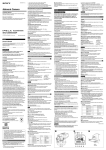
iPulse® Installation and User Guide
6. Appendix
Appendix A – Output Relay Configuration and Connections
(intelligent mode only)
Output Relay Configuration
The relay output configurations vary based on the manufactures design. Because of these
variations, the iPulse® I/O Detect input needs to operate in one of three ways. Refer to your
device user manual for more information regarding the output relay configuration to your device.
The following diagrams show proper connection to a device that is being run in iPulse intelligent
mode and should be referenced in instances where the included device chart does not specify the
output pins or terminals to be used when connecting to iPulse.
Dry Contact
The first and most common method requires the iPulse to supply current to the dry contacts of a
relay. This configuration is shown in Figure 5.
brown
Camera
Dry Contact
black
I/O Detect Cable
Figure 5: Dry Contact Relay I/O Detect Connection
12/6/2012
16