1
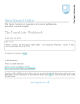
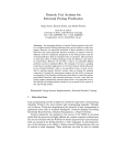
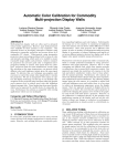
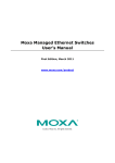
Fault-Tolerant Precision Time Protocol for
Smart Grids
Radu Onica, Nuno Neves, Antonio Casimiro
LaSIGE, Faculdade de Ciências, Universidade de Lisboa, Portugal
[email protected], [email protected], [email protected]
Abstract. The Precise Time Protocol defined in the IEEE 1588 standard is widely used to synchronize clocks, with a high degree of precision.
The current needs of time synchronization in Smart Grids are satisfied
with multiple GPS based clocks located around the network. This solution, however, is not cost efficient and if any of these GPS clocks is
successfully attacked, a part of the network can be rendered unusable.
This paper investigates a way of adding fault tolerance capabilities to the
PTP protocol to address attacks aiming to interfere with the GPS based
clock service. It is shown that the solution manages to detect anomalous
clock behaviors and recover from them. Furthermore, the solution is able
to deal with multiple GPS clock failures, as long as some correct time
source is still available.
Keywords: Precision Time Protocol, GPS Clocks, Fault Tolerant
1
Introduction
Smart grids are composed of different types of components, each with its own
requirements. Time synchronization plays a crucial role in the communication
and proper functioning of several of these components. One component in particular, the Phase Measurement Unit (PMU), depends almost entirely on high
accuracy time synchronization. The PMU measures and keeps track of various
parameters (e.g., electrical current amplitude and phase) of the part of the smart
grid where it is installed. This can be thought of as a ”snapshot” of the state in
which that portion of the smart grid is in. The deployment of multiple PMUs
at different points across the smart grid allows for a complete state estimation.
This information can then be used to support decisions on the need to modify
the power generation or the distribution of loads, which in turn gives the ability to predict and avoid failures like blackouts. Time synchronization among all
PMUs is critical to create a coherent picture of the smart grid. If PMUs take
snapshots at different times, the complete state cannot be correctly estimated.
Current PMUs use GPS receivers for time synchronization. This is a very costly
solution because it requires dedicated hardware to be present in each and every
PMU. From a security standpoint, it also leaves the PMUs, and in turn the
whole smart grid, vulnerable to even the most basic GPS attacks like blocking
or jamming [1].
1.1
Requirements
The requirements of a time synchronization protocol suitable for use in smart
grids are explained in detail in [2]. The standard is split into two parts: the
first one describes the measurement (called phasor in this context) estimation
requirements while the second one explains the network communication protocol.
The time synchronization requirements are presented as the maximum allowed
error for PMUs. This is translated into a need for the PMUs to make their
measurements at approximately the same time, within an interval of at most ≈
30µs.
Even though the standard does not talk about security requirements, the
protocol needs to be relatively secure and maintain timing errors below the
thresholds even in the case of an attack. The fact that each PMU is equipped
with a GPS receiver means that it also inherits all the insecurity and problems related to GPS, which in turn makes the implementation of a secure time
synchronization algorithm more difficult.
1.2
Precision Time Protocol
The precision time protocol appeared as a result of the growing need for high
precision time keeping. It was first described in the IEEE 1588-2002 standard,
officially entitled IEEE Standard for a Precision Clock Synchronization Protocol
for Network Measurement and Control Systems. A revised version appeared in
2008 as the IEEE 1588-2008 standard [3]. It was designed to fill in the gap left
open by the Network Time Protocol (NTP) and the Global Positioning System
(GPS) time service. It offers far better accuracy than NTP, but without the
need for a dedicated GPS receiver at each network node. GPS receivers can be
used in combination with a PTP network by acting as a Grandmaster Clock,
i.e., the time source for that network. A simple PTP network can be seen in
[Figure 1]. It is composed of a Grandmaster Clock that acts as a time source
for the network; a Boundary Clock that synchronizes itself to this Grandmaster
Clock; the Boundary Clock further synchronizes another part of the network,
namely a Slave Clock.
Since a PMU uses a GPS receiver to synchronize its local clock, it can be
seen as being made up of a Grandmaster Clock directly connected to a Boundary
Clock [Figure 1].
PTP uses the master-slave architecture for time distribution in which one
or more clocks are used as well as various communication media (e.g., network
links). It defines different roles for every clock in the network and different states
for every communication port in use:
– Grandmaster Clock: is a clock that synchronizes directly to a GPS receiver. It always runs in PTP Master mode, meaning it will distribute its
time throughout the network;
– Ordinary Clock: is a normal clock that synchronizes itself to another
source. It always runs in the PTP Slave mode;
– Boundary Clock: is a clock that both synchronizes itself to a PTP Master
(acting as a PTP Slave) and further distributes the time to another part of
the network (acting as a PTP Master). Only the PTP Slave port of the
Boundary Clock has the ability to make changes to the internal
clock. The other ports can only read the local clock;
– Transparent Clock: is a special type of clock that modifies all PTP messages that go through this device, correcting the message timestamps to
eliminate the time spent traversing the network equipment. This scheme
improves the time distribution accuracy by compensating for the time that
messages spend in each communication device (e.g., a switch).
PMU
Grandmaster Clock
Master Port
Network 1
Slave Port
Boundary Clock
Master Port
Network 2
Slave Port
Slave Clock
Typically a GPS receiver
Figure 1: A simple PTP Network where a PMU uses a GPS receiver (displayed
as a Grandmaster Clock) to synchronize its clock (represented as a Boundary
Clock).
The synchronization is achieved by exchanging PTP messages between the
master port of a clock and the slave port of another clock. The messages are
divided into event messages and general messages. Event messages are timestamped with both transmission and reception times. General messages do not
require accurate timestamps and are used for both synchronization and configuration purposes.
Based on timestamps, the slave calculates the time offset from the master
clock and eventually adjusts its local time to be similar to the master. The basic
synchronization message exchange is showed in [Figure 2] and the logic behind
it is explained below :
1. The master sends a Sync Message to the slave and saves the time t1 at which
it was transmitted;
2. The slave receives the Sync Message and notes the time of reception t2 ;
3. The master conveys to the slave the timestamp t1 by embedding it in a
Follow Up Message. Alternatively this timestamp can be embedded into the
Sync Message using some kind of hardware processing (this is called the
one-step mechanism);
4. The slave sends a Delay Req Message to the master and saves the time t3
at which it was transmitted;
5. The master receives the Delay Req Message and notes the time of reception
t4 ;
6. The master conveys to the slave the timestamp t4 by embedding it in a
Delay Resp Message.
Considering that the clock offset of the slave relative to the master is ∆ and
that the network delay between the master and slave is d(MS) and between the
slave and master is d(SM) we have:
t2 = t1 + ∆ + d(M S)
(1)
t4 = t3 − ∆ + d(SM )
(2)
Notice that we have two equations and three unknowns, which creates an
impossibility of resolution. The PTP standard makes the assumption that the
network delays are the same in both ways, i.e., d(MS)=d(SM)=d. Because of
this (1) and (2) can be simplified:
d=
t2 − t1 + t4 − t3
2
∆ = t2 − t1 − d
It is now possible to calculate both the one way delay as well as the clock
offset ∆. However, because of the aforementioned assumption, the calculated
clock offset will have an error that is equal to the difference between the mean
path delay and the master to slave delay.
The PTP standard utilizes an algorithm called Best Master Clock algorithm
(BMC) to select among the clocks the one to serve as the master. This clock
will provide reference time for the network. Selecting the best master takes into
account various parameters of each node:
– Clock quality - is the expected deviation from real time. In version 2 of
PTP, the clock quality is defined with two data fields, the clockAccuracy and
clockClass. The clockClass is used for transitioning a port from one state into
another in our implementation. By default, the values 13, 255 and 248 are
used respectively to designate a master only port, a slave only port or a
master/slave port. The Master/Slave port can run in either of these states.
In a PTP network, one will be Master and the rest will be Slaves. The BMC
algorithm is used to decide which one should be the Master. If a group of
clocks is run in Master only mode, after the best one is selected, all others
will go into a passive state (called PTP Passive);
– Priority - is represented by two 8-bit fields known as Priority1 and Priority2 ;
– Variance - is an estimation of the stability of the clock based on performance
observations;
– Identifier - is an universally unique numeric identifier of the clock and is
used as a tie breaker if all the other parameters are the same.
the adjustment of local clocks. At start up, a master/slave hierarchy is created using what is called the Best
Master Clock (BMC) algorithm to determine which clock has the best source of time. The BMC algorithm is
then run continuously to quickly adjust for changes in network configuration. Synchronisation is achieved
using a series of message transactions between master and slaves. There are five message types - Sync,
Delay Request, Follow Up, Delay Response and Management - which are used for all aspects of the
protocol. A sequence of message transactions takes place to synchronise a pair of clocks as shown in
Figure 2.1.
MS
SM
Figure
PTP Message
Figure
2.1: 2:
Master-Slave
offset Exchange.
measurement
1.3
Related work on PTP security
Several security related problems were discovered with PTP after the first version of the standard was released [4]. Annex K of the Precision Time Protocol
standard version 2 IEEE
1588-2008 [3] presents several security guidelines that
[email protected]
| www.tekroninternational.com
can help to withstand different types of attacks. The guidelines are however completely optional and in an experimental state. They focus on adding two main
security mechanisms:
– An integrity protection mechanism, which uses a Message Authentication
Code (MAC) to verify that messages have not suffered any unauthorized
modification in transit. A message counter is implemented to help prevent
replay attacks;
– An authentication method based on a challenge-response mechanism.
A flag in the PTP message is used to indicate that it is carrying security
related information. Each message following this one is required to also present
the same flag or else it is silently discarded without wasting any more resources.
In order to ease this process for hardware implementations, the flag should be
the last field in the message. By doing this, an indirect protection against Denial
of Service attacks on system resources is created.
In [5] a comprehensive threat analysis of the PTP protocol is done and solutions using IPsec and MACsec are explored.
GPS receivers are often used as the time source for the smart grid, which
makes it a prime target for attackers. Some research has been previously done
on various types of attacks on GPS receivers, like Blocking, Jamming [1] or
Spoofing [6]. Blocking attacks try to isolate the receiver from the satellite signal
leading to a signal loss. In jamming attacks, significant RF (radio-frequency)
noise is transmitted so that the receiver can no longer get the satellite signal.
Spoofing attacks generate fake GPS signals that cause the receiver to calculate
an incorrect location and/or time solution.
Recently a more advanced type of attack that targets the receiver itself was
demonstrated [7]. It alters the satellite signal data in such a way as to make
the receiver output incorrect results or downright crash. These types of attacks
are becoming more common because of the relatively cheap cost of the Spoofer
Device (called Phase-Coherent Signal Synthesizer) as well as the continuously
expanding attack vector of recent GPS receivers. Manufacturers of GPS receivers
are adding more configuration and connectivity ”features” that normally have
security as an afterthought and are easy to break using a custom GPS satellite
signal.
1.4
Proposed solution
Our solution is based on modifying a PTP Boundary Clock [Figure 3a]. The
modified Boundary Clock [Figure 3b] acts like a normal Boundary Clock but
has an additional port that will act as a backup in the case the Grandmaster
Clock fails. This backup port will be connected with other backup ports of
the various Boundary Clocks distributed throughout the network. To ensure
time synchronization among all nodes, we need to have several such GPS based
Grandmaster Clocks and various Boundary Clocks around the network to ensure
geographical distribution. Instead of using a GPS Grandmaster Clock for each
Boundary Clock, the same Grandmaster Clock is able to synchronize various
Boundary Clocks as long as the network delays and jitter allow it, reducing the
total number of GPS Grandmaster Clocks and as a result, the cost.
Under
Attack
Backup Port
Backup Port
Grandmaster Clock
PTP Slave
PTP Master
Internal Clock
(a)
Slave Clock
Grandmaster Clock
PTP Slave
PTP Master
Slave Clock
Internal Clock
(b)
Figure 3: Boundary Clock as originally defined by PTP (a) and with the
proposed modification (b).
Not only does our solution manage to reduce the number of GPS receivers
needed but it also allows for the detection and mitigation of GPS attacks. This
allows the node to always synchronize itself to a time source even if it is not as
good as the original.
2
Attack Model
Our focus is on detecting and mitigating attacks on the GPS receiver (i.e., Grandmaster Clock) that offers time information to the boundary clock as well as on
the communication link between them. There is an initial prerequisite that all
boundary clocks are synchronized to a correct time source before any
attacks occur.
Attacks against the Grandmaster Clock can cause it to fail in several different
ways. We abstract these failures in two classes, as perceived by the Boundary
Clock:
– Crash faults are observed when the Grandmaster Clock is incapable of
sending any type of information to the Boundary Clock. This can happen
when the GPS receiver of the Grandmaster Clock is:
– under a Blocking or Jamming attack and loses its satellite signal lock;
– under a Software Attack that crashes the GPS receiver;
– Arbitrary faults (or Byzantine [8]) are assumed when the information
received by the Boundary Clock from the Grandmaster Clock is incorrect
in any way, or when it reaches the Boundary Clock late or in an arbitrary
order. This can happen when the GPS receiver of the Grandmaster Clock is:
– under a Spoofing Attack that causes the Grandmaster Clock to give usable
but incorrect data;
– under a Software Attack that renders the Grandmaster Clock unable to
provide any kind of usable information.
A Byzantine fault is also assumed when the Communication Link interconnecting the Grandmaster Clock to the Boundary Clock is under attack, which
in turn causes the time information to be delayed or to reach the Boundary
Clock in an incorrect order.
3
System Architecture
We define three new port states based on the existing three states of PTP Master,
PTP Passive and a PTP Slave. The new port states are called Fault-Tolerant
(FT) PTP Master, FT PTP Passive and FT PTP Slave respectively [see Figure 4]. As previously mentioned, our modified Boundary Clock distinguishes
itself from a normal one by the presence of one extra port that will interconnect
various such Boundary Clocks.
– FT PTP Slave has the purpose to detect abnormal activity coming from
the Master port it is connected to (in our case this will be the Grandmaster
Clock port) and to alert the backup port. It does this by analyzing the time
information coming from the Grandmaster Clock, as well as the network
delay between them;
– FT PTP Master and FT PTP Passive are port states in which the
newly added backup port of the Boundary Clock will run. Their primary
purpose is to distribute time information (if the Grandmaster Clock where
it synchronizes itself is still considered correct) to other Boundary Clocks.
The normal PTP Slave port of the Boundary Clock is replaced with a FT
PTP Slave. As mentioned before, the backup port of the Boundary Clock will
either run in FT PTP Master or FT PTP Passive modes. A modified version
of the Best Master Clock algorithm runs between the backup ports with the
responsibility of deciding which one will be the FT PTP Master. After the best
FT PTP Master is selected, all the other ports will run in FT PTP Passive. The
modified version of the BMC algorithm takes into account another parameter
used for disqualifying one such port from the algorithm.
GPS Receiver
Grandmaster Clock
Internal Clock
PTP Slave
PTP Slave
FT PTP Slave
PTP Master
PTP Slave
PTP Slave
Modified BMC Algorithm
FT PTP Master
GPS Receiver
Grandmaster Clock
PTP Slave
FT PTP Passive
FT PTP Passive
FT PTP Passive
FT PTP Passive
FT PTP Passive
FT PTP Passive
FT PTP Passive
PTP Slave
PTP Slave
FT PTP Slave
PTP Master
PTP Slave
PTP Slave
PTP Slave
Internal Clock
Figure 4: System Architecture
4
Detecting and Recovering from Failures
In this section we describe how the detection and recovery mechanism works. The
state of the Boundary Clock during normal operation and when under attack
are presented in [Figure 5a] and [Figure 5b].
When an attack is detected by the FT PTP Slave, it first does a clock jump1
of 2 * DEFAULT SYNC INTERVAL (1 second in our implementation) ahead,
then proceed to disable itself. The backup port (running in either FT PTP
Master or FT PTP Passive) observes the clock jump by reading the clock at
each full run of the protocol. Next, it goes into a normal PTP Slave mode. Any
out of the ordinary modifications to the internal clock of the Boundary Clock
are detected and handled in this way. The backup port can be in two different
states when an attack is discovered: FT PTP Master or FT PTP Passive. If the
current state is FT PTP Master, another backup port will need to be elected to
go into FT PTP Master state. A modified BMC algorithm is used to perform this
change, by comparing data from all the backup ports of the Boundary Clocks.
Notice that we use the local clock of the Boundary Clock as a means to
communicate failure detection between the two ports. This is done in order to
minimize changes to the standard. However, a low level, high speed communication scheme as presented in [9] can help with the recovery time. The clock
jump performed by the FT PTP Slave will always have to be greater than the
DEFAULT SYNC INTERVAL because we need to make sure that the FT PT
Master (now in PTP Slave state) will receive at least one Sync Message from
the new time source (in this case a FT PTP Master port from another boundary
clock) to compare the origin timestamp from this Sync Message to the current
local clock time.
The state change from FT PTP Master to PTP Slave is carried out by
modifying the clock class value of this port from 13 (associated with a Master
only port) to 255 (Slave only port). Once into PTP Slave mode this port will
start synchronizing to another FT PTP Master and the previously set local clock
jump will be immediately detected and corrected. In the worst case scenario
the recovery time is DEFAULT SYNC INTERVAL + PTP Slave Initialization
Time.
Under
Attack
Under
Attack
FT PTP Passive
Clock Jump
FT PTP Slave
PTP Master
Internal Clock
(a)
Detect Clock Jump
PTP Slave
FT PTP Master
Grandmaster Clock
FT PTP Master
Slave Clock
Grandmaster Clock
Disa‐
bled
PTP Master
Slave Clock
Internal Clock
(b)
Figure 5: Boundary Clock state during normal operation (a) and after an
attack is detected (b)
1
A sudden change in the order of milliseconds or larger of the internal clock time.
Next we describe in more detail how the detection mechanism implemented
in the FT PTP Slave works for crash and byzantine faults.
4.1
Crash failure detection
The crash failure detection mechanism is based on the periodic transmission of
Announce Messages. The normal behavior of the Grandmaster Clock is to send
an Announce Message every DEFAULT ANNOUNCE INTERVAL (1 second in
our implementation). The FT PTP Slave keeps track of the received announce
messages and waits a maximum of announceTimeoutGracePeriod (with a value
of 3 seconds) before declaring a packet as lost. We consider the Grandmaster
clock failed if two Announce Messages are lost. This translates to a maximum
wait time of 6 seconds, which is a lot but serves as a means of testing and
verifying the algorithm. Of course, the bounds could be made tighter but with
the cost of an increased performance overhead.
4.2
Byzantine failure detection
As a first detection layer all information reaching the Boundary Clock from the
Grandmaster Clock is filtered to eliminate any bogus data. This will prevent
most arbitrary behaviors that cause the transmission of unexpected data. From
the previously mentioned attacks, the only one that can do this is the GPS
Software attack. This scenario encompasses most of the attack vectors but two
cases need to be treated separately because of the their volatile nature:
– Attacks on time. In this type of attack the goal is to try to provide inaccurate time information to the Boundary Clock to desynchronize it. The
primary information used to detect these attacks comes from Sync Messages.
An attack can occur in two different ways: either the provided time value
jumps forward by a significant amount in one step (clock jump), or the clock
is skewed2 gradually step by step. In order to detect both types, we save the
values of the clock offset between the Grandmaster Clock and the Boundary Clock after the clocks are synchronized (Original offset), and the offset
calculated in the last execution cycle of the algorithm, which is based on
the latest received Sync Message. We know that the values will vary very
little considering that clocks are already synchronized (prerequisite). So if
an attacker tries to jump the clock this will be discovered by comparing the
original offset with every new calculated offset. The values used to define
the maximum allowed offsets are: MAX SECONDS ALLOWED OFFSET,
and MAX ALLOWED DRIFT (in ns). The first one is used to detect offset
jumps in the order of seconds.
The second one is employed to either find clock jumps by comparing the
last known offset with the newly calculated one, or to discover skews by
comparing the original offset with the newly calculated one. Special care
2
A change in the order of µs or slower relative to the internal clock time.
needs to be given to the MAX ALLOWED DRIFT parameter because it
represents the maximum value that the Boundary Clock time is allowed to
change at each execution cycle. If an attack increases the clock offset at a
rate slower than the MAX ALLOWED DRIFT parameter, time data from
other backup ports can be used to detect it. Two maximum offset values
were used because time is represented by two fields (seconds and subseconds
field) in our implementation. The MAX SECONDS ALLOWED OFFSET
and MAX ALLOWED DRIFT parameters need to be adjusted by measuring and averaging the clock offset and network delays between the Grandmaster Clock and Boundary Clock;
– Attacks on the communication link. As previously mentioned the attacker has total control over the communication link between the Grandmaster Clock and the Boundary Clock. This allows him to delay or drop
PTP packets. Dropped packets will make the Boundary Clock think the
Grandmaster Clock has crashed, and it will act accordingly.
Delay detection is done in a similar way to the detection of Attacks on time
but using the network delay as primary information. The delay is calculated
by means of the standard Delay request-response mechanism [Section 1.2].
Once again we save the first calculated delay value after the clocks are synchronized and the one computed in the last cycle of the algorithm. The
main difference consists in the fact that network delays can vary more than
the clock offset. Therefore, instead of immediately considering the Grandmaster Clocks failed, we consider deviations from the normal delay to be
outliers. For a delay value to be considered an outlier it has to be greater
than MAX OUTLIER DEVIATION (in ns). When a sufficient number of
outliers (MAX DELAY OUTLIERS ) are detected over a period of time, the
Boundary Clock will consider the Grandmaster Clock failed and act accordingly.
4.3
Modified Best Master Clock Algorithm
The main modification on the BMC algorithm was the introduction of a new
parameter called isCandidate. This parameter is verified in each execution cycle
of the algorithm and is used to disqualify the FT PTP Master/FT PTP Passive
port of the Boundary Clock, when it goes into PTP Slave mode (when an attack
is detected). When this change is observed by the remote Boundary Clocks,
a new FT PTP Master is elected for the network. In order to exchange the
isCandidate value between all the Boundary Clocks the Announce Message was
used.
5
5.1
Experimental Evaluation
Testing Platform
The open source ptpd2 [10] project was used as a base for our implementation
on three Ubuntu 14.10 machines. Ptpd2 is specifically tailored to be used as a
software only implementation [11] without any hardware assistance.
One of the machines was equipped with two network cards (one for the FT
PTP Slave port and one for the FT PTP Master/FT PTP Passive port) and
played the role of the Boundary Clock. The other two machines simulated a
Grandmaster Clock (running a normal PTP Master) and a second Boundary
Clock with a backup FT PTP Master/FT PTP Passive port, to act as a new
time source when the first one fails. We did not simulate the other normal PTP
Master port of the Boundary Clock and the network it synchronizes because it
is just a normal PTP network.
Since we used off-the-shelf PC machines, the internal oscillators of the clocks
are of low quality. If left unsynchronized, they drift apart by a large amount
in a relatively short span of time. This would not happen in a real smart grid
network because the PMU’s oscillators are of a better quality. The test network
was a normal 100 Mbps Ethernet LAN with a lot of nodes, traffic and jitter. It is
safe to assume that the network conditions in a smart grid environment will be
considerably better. However all nodes are relatively close geographically, closer
than in some deployment scenarios of a smart grid network.
5.2
Results
We experimented our algorithm in three test cases. Our first test case consisted
in injecting a Crash fault [Figure 6]. This was simulated by simply killing the
PTP process running on the Grandmaster Clock machine. This was done at time
”08”. After exactly 6 seconds (as previously described 2 *
source
ANNOUNCE INTERVAL) the Grandmaster clock was considered
DEFAULT
failed. At that moment the FT PTP Slave port of the Boundary Clock increased
the internal clock by 2 seconds and proceeded to disable itself. The FT PTP
Master/FT PTP Passive port now detects the clock skew and goes into PTP
Slave mode. After receiving the first Sync message from a FT PTP Master port
of another Boundary Clock the synchronization process starts.
Boundary Clock Time
Crash fault
00 01 02 03 04 05 06 07 08 09 10 11 12 13 14 17 16 17 18 19 20 21 22 23 24 25 26 27 28 29 30
16
Attack Time
Detection Time
14
Clock Offset (μs)
12
10
8
6
4
2
0
Real Time
Synchronized to Grandmaster Clock
Synchronized to another Boundary Clock
Figure 6: Crash fault detection and recovery
The second test case is an attack on time. This can happen in two ways:
either by skewing the clock or by jumping it a large amount at once. We present
results for the first case, which is harder to detect. The second case detection
scheme is similar except we compare the current local time to
MAX SECONDS ALLOWED OFFSET instead of MAX ALLOWED DRIFT.
The results would also be similar because nothing else changes. A bash script
was created and ran on the Grandmaster Clock machine. It will skew the clock
by a small amount by performing a small set of simple operations. The script
reads the value of the clock, saves this value into a variable then proceeds to
set the clock to the value of that variable. This works because it takes ' 1 ms
to set a variable in memory in our machines. [Figure 7] shows the perceived
increase in the clock offset of the Master (appearing on a logarithmic scale in
the graph) that is suffering the attack (left side of the graph). The value for the
MAX ALLOWED DRIFT parameter used for this test was 700 µs.
Clock Offset - Clock Step
1000
Attack Time
Detection Time
MAX_ALLOWED_DRIFT
Clock offset (μs)
100
10
1
1
2
3
4
5
6
7
8
9 10 11 12 13 14 15 16 17 18 19 20 21 22 23 24 25 26 27
Figure 7: Gradual Clock Skew
The last case we tested was when the attacker delays PTP packets sent by
the Grandmaster Clock. The MAX OUTLIER DEVIATION was set to 300 µs
and the MAX DELAY OUTLIERS was set to 3. To simulating the delays we
employed the tc command [12]. The tc command is used to show or manipulate
traffic control settings. This allowed us to introduce a 450 µs delay in the network.
We can see from the graph [Figure 8] that the delays of the new communication
link between the FT PTP Master/FT PTP Passive (now in PTP Slave state)
port of the Boundary Clock and a FT PTP Master port from another Boundary
Clock are not as stable as the ones between the Grandmaster Clock and the
FT PTP Slave port (now disabled). This is due to the fact that the delays are
calculated based on the clock offset and the first Boundary Clock is not yet fully
synchronized to the new time source. After some time they will normalize and
become stable.
Ordinary Clock Time
Master-Slave Delay (μs)
600
Network Attack - Packet Delay
50 51 52 53 54 55 56 57 58 59 0 1 2 3 4 5 6 7 10 9 10 11 12 13 14 15 16 17 18 19 20
Attack Time
Detection Time
500
400
300
200
100
0
Real Time
Synchronized to Grandmaster Clock
Synchronized to another Boundary Clock
Figure 8: Packet Delay Attack
6
Conclusions
The evolving needs of the smart grid bring a new set of problems that has to be
addressed. Time synchronization in such an environment is a critical necessity.
This requirement is currently realized by the used of various GPS receivers,
which creates a large attack surface for attackers to exploit. In this paper we
presented a new approach to using PTP in a smart grid environment while
trying to keep the modifications to the standard to a minimum. We have shown
that this solution is successful in mitigating all types of attacks as long as our
requirements are met. Further research can be done to see how the protocol
behaves in a real-world smart grid environment as well as the impact it has on
specific parts of the network while under attack.
7
Acknowledgments
This work was partially supported by the EC through project FP7 SEGRID
(607109), by national funds of Fundação para a Ciência e a Tecnologia (FCT)
through project UID/CEC/00408/2013 (LaSIGE).
References
1. H. Hu and N. Wei, “A study of GPS jamming and anti-jamming,” in Proceedings of
the International Conference on Power Electronics and Intelligent Transportation
System, vol. 1, pp. 388–391, Dec 2009.
2. “IEEE Standard for Synchrophasor Measurements for Power Systems,” IEEE Std.
C37.118.2011, Dec 2011.
3. “IEEE Standard for a Precision Clock Synchronization Protocol for Networked
Measurement and Control Systems,” IEEE Std 1588-2008 (Revision of IEEE Std
1588-2002), pp. c1–269, July 2008.
4. J. Tsang and K. Beznosov, “A Security Analysis of the Precise Time Protocol,” in
Information and Communications Security, Lecture Notes in Computer Science,
2006.
5. T. Mizrahi, “Time synchronization security using IPsec and MACsec,” in Proceedings of the International IEEE Symposium on Precision Clock Synchronization for
Measurement Control and Communication, pp. 38–43, Sept 2011.
6. J. Larcom and H. Liu, “Modeling and characterization of GPS spoofing,” in Proceedings of the IEEE International Conference on Technologies for Homeland Security, pp. 729–734, Nov 2013.
7. T. Nighswander, B. Ledvina, J. Diamond, R. Brumley, and D. Brumley, “GPS
Software Attacks,” in Proceedings of the ACM Conference on Computer and Communications Security, pp. 450–461, 2012.
8. L. Lamport, R. Shostak, and M. Pease, “The Byzantine Generals Problem,” ACM
Trans. Program. Lang. Syst., vol. 4, pp. 382–401, July 1982.
9. X.-H. Cheng and L. Zhang, “A research of inter-process communication based on
shared memory and address-mapping,” in Proceedings of the International Conference on Computer Science and Network Technology, vol. 1, pp. 111–114, Dec
2011.
10. Precision Time Protocol Daemon - ptpd2, Feb. 2011. http://ptpd2.sourceforge.net.
11. M. B. Kendall Correll, Nick Barendt, “Design Considerations for Software Only
Implementations of the IEEE 1588 Precision Time Protocol,” in Proceedings of the
International Conference on IEEE 1588 Standard for a Precision Clock Synchronization Protocol for Networked Measurement and Control Systems, 2006.
12. TC Linux User’s Manual, Dec 2001. http://lartc.org/manpages/tc.txt.