1
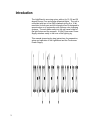
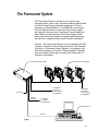
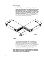
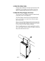
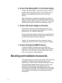
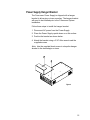
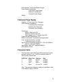
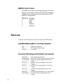
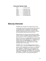
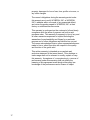
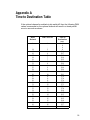
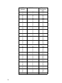
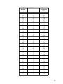
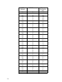
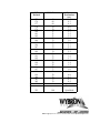
THE
LightWand
User Manual
LightWand Moving Mirror
Power Supply
Manual revision: 03/13/02
CONTENTS
Introduction .................................................................3
The Forerunner System ..............................................4
Power Supply ........................................................5
Cables....................................................................5
DMX Interface .............................................................6
16 Bit Pan/Tilt: Figure 1 ..............................................7
8 Bit Pan/Tilt: Figure 2 ................................................8
Setup for the LightWand .............................................9
Mounting and Installation Accessories .....................11
Power Supply Hanger Bracket ............................12
LightWand Mounting Plate ..................................13
Specifications ............................................................13
Parts List ...................................................................15
Warranty Information ................................................16
Appendix A................................................................18
2
Introduction
The LightWand is a moving mirror add-on for 19, 26 and 36
degree Source Four and similar ellipsoidal lights. The unit is
controlled with two to five DMX channels giving 8 or 16 bit
resolution for both pan and tilt information and is designed to
operate alone or in conjunction with Wybron color changing
systems. The unit slides easily into the gel frame holder of
the light fixture and the compact, 16-Way Forerunner Power
Supply attaches easily to the truss of the lighting rig.
This manual gives step-by-step instructions for preparation,
setup and operation of the LightWand and the Forerunner
Power Supply.
/home/angie/Object1.agdoesnotexist!
3
The Forerunner System
The Forerunner System consists of one or more color
changers and/or one or more LightWand Moving Mirrors and
a remote Power Supply which can power up to 16 color
changers or 8 Moving Mirrors. The DMX512 control signal
from the lighting board is connected to the Power Supply
and can continue onto more Forerunner Power Supplies or
other DMX-controlled devices. The Power Supply sends
both power and control signal on a single cable eliminating
the need for a separate power cable for each LightWand.
Caution: The Forerunner System is not compatible with The
Coloram II System. Do not connect products in the Coloram
II System to Forerunner Power Supplies, or products in the
Forerunner System to Coloram II Power Supplies. Damage
from such action will not be covered by the Forerunner or
Coloram II warranties.
The Forerunner Power Supply
The Forerunner Color Changer
ADJ
ADJ
UST
GEL
LOA
D GEL
ADJ
UST
GEL
LOA
D GEL
To additional
Forerunner
Color Changers
or LightWands
AC Power
Buffered
DMX512
UST
ADJ
GEL
LOA
D GEL
UST
GEL
LOA
D GEL
To additional
Forerunner
Color Changers
or LightWands
To additional
Forerunner
Power Supplies
DMX Control con
DMX CONSOLE
DMX512
Figure 1
4
Power Supply
The Power Supply has two Color Changer/Moving Mirror
outputs and provides each Color Changer/Moving Mirror with
DMX signal and 24 volts DC. The Power Supply features a
DMX bypass relay to pass the DMX signal to the DMX output
connector in the event of AC power loss. The Power Supply
automatically accommodates 85 - 132 VAC (50/60 Hz) or
170 - 264 VAC (50/60 Hz). AC power is indicated by a red
LED which can be viewed from the stage.
Figure 4
Cables
The Forerunner cable connects each of the two Power
Supply outputs to a daisy chain of up to four LightWand
Moving Mirrors or eight Forerunner Color Changers and
provides the Moving Mirrors/Color Changers with power and
control signal. The Forerunner cable uses 4-pin XLR
connectors on either end and consists of two -14 AWG
conductors and a 22 AWG twisted, shielded pair.
Note: The cable used in the Forerunner System is the same cable
which is used in the Coloram II System and may be referred to as
either Coloram II cable or Forerunner cable.
5
DMX Interface
The Light Wand uses 2 to 5 DMX channels as selected by
the user. Eight or 16 bit pan/tilt modes are selected via dip
switch number 1 (using 2 or 4 DMX channels respectively).
See Figures 1 and 2 for the channel assignment charts. An
optional channel exists and can be turned on via dip switch
number 2. The optional channel is channel 3 in 8 bit mode
or channel 5 in 16 bit mode. The optional channel controls
spin mode and timed pan/tilt movement.
Spin Mode
When the optional channel is set to 80% or above, the unit
will go into spin mode. Channel 1 then controls spin speed
and direction (see the DMX channel definitions). When spin
mode is commanded, the unit will complete any pan/tilt move
in progress, then spin mode will be started. Once the unit is
in spin mode, the tilt position cannot be changed. It is
possible to command a new tilt position at the same time as
commanding spin to start. The unit will first perform the tilt
move and then spin mode will be started. When spin mode
is exited, the unit will go to the currently commanded pan/tilt
position.
Timed Pan/Tilt Moves
The optional channel also allows for a timed pan/tilt move.
Values can be selected from 0 to 30 seconds for a move.
See the time channel table in Appendix A for DMX values
and the corresponding time to position values. For a point to
point pan/tilt move, smoother results will be obtained by
performing a timed move than by doing a pan/tilt DMX fade
from the console.
6
DMX Channel Definitions
16 Bit Pan/Tilt
DMX
DMX
Channel 2
Channel 1
Fast
Channel 3
Channel 4
Channel 5
100
100
Spin
Mode
On
Spin
Clockwise
Pan
High
80
79
Slow 55
54
Stop
Pan
Low
Tilt
High
Time to
Destination
Spin
Counter
Clockwise
6
5
0
0
Figure 1
7
30 sec
Tilt
Low
46
Slow 45
Fast
Optional
.2 sec
0 sec
DMX Channel Definitions
8 Bit Pan/Tilt
DMX
Channel 2
Channel 1
Fast
DMX
100
Channel 3
100
Spin
Mode
On
Spin
Clockwise
Pan
High
Optional
80
79
Slow 55
54
Stop
30 sec
Tilt
High
46
Slow 45
Time to
Destination
Spin
Counter
Clockwise
6
5
Fast
0
0
.2 sec
0 sec
Figure 2
8
Setup for the LightWand
To get your Forerunner System up and running, follow these
hookup and checkout procedures.
1. Set the DMX512 Moving Mirror Channel
Each Moving Mirror is assigned an individual DMX address
to which it will respond from the lighting console. The
address is set via the three rotary switches located on the
back of each Moving Mirror. Valid DMX addresses are 001 511.
Set the DMX starting channel on the three rotary switches.
The red LED indicates that the unit is powered. The blinking
green LED indicates that the unit is receiving DMX control
data.
2. Set the Dip Switches
Set dip switch number 1 to select between 8 and 16 bit
pan/tilt mode.
Set dip switch number 2 to select the Optional DMX channel
on or off (see description of the Optional Channel in the
DMX Interface section above).
Set dip switch number 3 to select Shortest Path Mode on or
off. If the unit is in shortest path mode it will travel the
shortest distance to a new pan destination even if it means
spinning around the "back" side of the unit.
3. Attach the Moving Mirror to the Lamp
Slide the Moving Mirror’s mounting bracket into the gel frame
holder of your lamp and lock the gel frame retention clip (if
available).
If the mounting plate installed on your Moving Mirror doesn’t
fit the fixture, you may replace it with a differently sized plate.
See page 11 for information on changing mounting plates.
9
4. Attach the Safety Cable
A safety cable is attached to the back, right hand side of the
LightWand. Run this cable around the pipe or truss from
which you hang the light fixture and clip it to itself (fig. 5).
5. Attach the Power Supply to the truss
The Forerunner Power Supply is designed to attach directly
to the pipe or truss of your lighting rig.
The Power Supply comes with a mounting bracket which
hooks over the pipe or truss and is then locked into place
with a thumb screw.
Once you have the Power Supply positioned and locked into
place, connect the safety cable by running it around the pipe
or truss to which the Power Supply is attached.
Note: For cabling purposes, it may be preferable to position
your Power Supply toward the center of the pipe or truss and
daisy chain either direction from it.
igure 5
10
6. Connect the Moving Mirror to the Power Supply
Connect the Moving Mirror to the Power Supply using the
supplied 4-pin power/signal cable. The connectors are on
the back of the LightWand and the front of the Power
Supply.
Note: Both power and signal are supplied to the Moving
Mirror on the same cable. The Power Supply has two Color
Changer outputs. Each output will control up to four Moving
Mirrors with a maximum of 350 feet of cable per output.
7. Connect the Power Supply to AC Power
Plug the AC cord into a non-dimmed power circuit. The
power supply automatically accommodates 85 - 132 VAC
(50/60 Hz) or 170 - 264 VAC (50/60 Hz).
Power at the Power Supply is indicated by a red LED which
can be viewed from the stage. Power is also indicated by a
red LED on the bottom of each LightWand.
Caution: Do not power the unit from a dimmer. Severe
damage will result, and is not covered by product warranty.
7. Connect and Set the DMX512 Source
Connect the DMX512 signal source to the DMX input
connector on the front of the Power Supply using standard
DMX cable. Valid DMX signal will be indicated by a green
LED on the bottom of each LightWand.
Mounting and Installation Accessories
The components of your Forerunner System may require the
installation of additional mounting accessories or the
replacement of others. Some of these accessories, such as
the Power Supply hanger bracket and your choice of one
LightWand mounting plate, are supplied while other
accessories, such as additional mounting plates, may need
to be purchased separately. The following sections describe
the procedures for installation and replacement of these
accessories.
11
Power Supply Hanger Bracket
The Forerunner Power Supply is shipped with a hanger
bracket to allow pipe or truss mounting. The hanger bracket
will need to be installed prior to the Forerunner System
installation.
Follow these steps to install the hanger bracket.
1. Disconnect AC power from the Power Supply.
2. Place the Power Supply upside down on a flat surface.
3. Position the bracket as shown below.
4. Attach the bracket using a 3/16" Allen wrench and the
supplied screws.
Note: Use the supplied thumb screw to clamp the hanger
bracket to the desired pipe or truss.
Figure 6
12
LightWand Mounting Plate
The LightWand ships with your choice of available mounting
plates installed. It may be necessary, when mounting the
LightWand on different light fixtures, to replace the mounting
plate.
Follow these instructions to replace the mounting plate.
1. Place the LightWand on a flat surface.
2. Unscrew the four screws which hold the current mounting
plate on.
3. Place the replacement mounting plate on the LightWand,
aligning the screw holes properly.
4. Fasten the four corners of the mounting plate to the
LightWand using the same screws you removed in step
2.
Note: Always use the supplied screws, as they are treated
with an anti-vibration compound to keep them from
loosening.
Specifications
LightWand Moving Mirror
DMX : Uses two to four DMX channels
Tilt: 46 degrees of motion
Pan: 360 degrees of motion
Fan: Single speed - normal
Pan/Tilt Resolution: 0.02 degree position
Pan/Tilt Move Speed: ~40 degrees/second
Current: .6A draw
Fuse: 1.5A SloBlo
Individual DMX address: 001 - 512
Upgrade Features: four DIP switches included on the unit
for future upgrades
Fixture compatibility (with optional mounting plates):
19, 26 and 36 degree Source Four and similar
ellipsoidal lights.
13
LED Indicators: Power and DMX512 signal
Power Supply compatibility:
Forerunner Power Supply
Rainbow Power Supply
ChromaQ Power Supply
Weight:
Forerunner Power Supply
Capacity: 16 Forerunner Color Changers
Color Changer compatibility:
Forerunner Color Changers
Rainbow Color Changers
ChromaQ Color Changers
Connectors:
DMX in: Male 5-pin XLR
DMX out: Female 5-pin XLR
Color Changer out x 2: Female 4-pin XLR
Power loss DMX bypass relay: Yes
DMX512 termination: Terminated and regenerated
Fuse: 2 amp slow blow at 115 VAC
1 amp slow blow at 230 VAC
Input Power: Automatically accepts 85 - 132 VAC 50/60 Hz
and 170 - 264 VAC 50/60Hz
Input Signal: 1990 USITT standard DMX512
LED indicator: Power
Forerunner Cable
The Forerunner cable uses 4-pin XLR connectors on either
end and consists of two -14 AWG conductors and a 22
AWG twisted, shielded pair.
XLR Pin #
1
2
3
4
Wire Color
White
Green
Red
Black
Function
Ground
Data Data +
24 Volts DC
Size
14 AWG
22 AWG
22 AWG
14 AWG
Note: The maximum amount of cable per LightWand output
on the power supply is 350 feet.
14
DMX512 Control Cable
The DMX control cable from the lighting board to the Power
Supply is a five conductor cable with 5-pin XLR connectors
on each end. The wiring pin out is specified by the USITT
DMX512/ 1990 standard.
XLR Pin #
1
2
3
4
5
Function
Common
Data Data +
Talkback Talkback +
Parts List
To order any of the following items, contact your authorized WYBRON dealer.
LightWand Moving Mirror and Power Supplies
4570........................ LightWand Moving Mirror
7150........................ The Forerunner Power Supply
715-08-01 ............... User Manual
Forerunner Mounting and Installation Accessories
715-01-03P............. Power Supply hanger bracket
SCRWC252075 ...... Wing screw for Power Supply hanger bracket to pipe
SCRSC2520037 ..... Socket cap screw for hanger bracket to Power
................................ Supply
452-01-03P............. 6.25"/158.75mm mounting plate for 4 inch Color
................................ Changer
452-03-04 ............... 6.25"/158.75mm mounting plate for 7 inch Color
................................ Changer
703-01-03P............. 7.5"/190.5mm mounting plate for 7 inch Color
................................ Changer
703-01-05P............. 10"/254mm mounting plate for 7 inch Color Changer
SCRPH832037 ....... Pan head screws for mounting plate to Color
................................ Changer
15
Forerunner System Cable
7042-3 .................... 3’ power/signal cable
7042-5 .................... 5’ power/signal cable
7042-10 .................. 10’ power/signal cable
7042-15 .................. 15’ power/signal cable
7042-25 .................. 25’ power/signal cable
7042-50 .................. 50’ power/signal cable
7042-75 .................. 75’ power/signal cable
7042-100 ................ 100’ power/signal cable
Warranty Information
WYBRON, INC. warrants to the original owner or retail
customer that for a period of one year from date of delivery
of a portable system or energization of a permanently
installed system (up to a maximum of 18 months from
delivery) its products will be free from defects in materials
and workmanship under normal use and service.
Warranty does not cover any product or part of a product
subject to accident, negligence, alteration, abuse, misuse or
any accessories or parts not supplied by WYBRON, INC..
Warranty does not cover "consumable" parts such as fuses,
lamps, or color media. WYBRON, INC.’s warranty does not
extend to items not manufactured by us. Freight terms on
warranty repairs are FOB WYBRON, INC. factory or
designated repair facility. Collect shipments or freight
allowances will not be accepted.
WYBRON, INC.’s sole responsibility under this warranty
shall be to repair or replace at WYBRON, INC.’s option such
parts as shall be determined to be defected on WYBRON,
INC.’s inspection. WYBRON, INC. will not assume any
responsibility for any labor expended or materials used to
repair any equipment without WYBRON, INC.’s prior written
authorization . WYBRON, INC. shall not be responsible for
any incidental, general or consequential damages to
16
property, damages for loss of use, time, profits or income, or
any other charges.
The owner’s obligations during the warranty period under
this warranty are to notify WYBRON, INC. at WYBRON,
INC.’s address within one week of any suspected defect,
and return the goods prepaid to WYBRON, INC. at their
factory or authorized service center.
This warranty is contingent on the customer’s full and timely
compliance with the terms of payment set forth in said
purchase order. This warranty is expressly in lieu of any and
all other warranties expressed or implied including the
warranties of merchantability and fitness for a particular
purpose and of other obligations and liabilities on our part.
The owner acknowledges that no other representations were
made to him or relied upon him with respect to the quality
and function of the goods sold.
This written warranty is intended as a complete and
exclusive statement of the terms thereof. Prior dealings or
trade usage shall not be relevant to modify, explain or vary
this warranty. Acceptance of, or acquiescing in, a course of
performance under this warranty shall not modify the
meaning of this agreement even though either party has
knowledge of the performance and a chance to object.
17
Appendix A
Time to Destination Table
If the optional channel is enabled via dip switch #2 then the following DMX
values commanded on the optional channel will result in a timed pan/tilt
move in seconds as shown.
DMX
Decimal
DMX Percent
0
.
.
14
15
16
17
18
19
20
21
22
23
24
25
26
27
28
29
30
31
32
33
34
35
36
37
38
39
40
41
42
0
.
.
5
6
6
7
7
7
8
8
9
9
9
10
10
11
11
11
12
12
13
13
13
14
14
15
15
15
16
16
16
Time to
Destination
(sec)
0
0
0
0
29.8
29.7
29.5
29.4
29.2
29.0
28.9
28.7
28.6
28.4
28.3
28.1
27.9
27.8
27.6
27.5
27.3
27.1
27.0
26.8
26.7
26.5
26.3
26.2
26.0
25.9
25.7
25.6
18
19
DMX
Decimal
DMX Percent
43
44
45
46
47
48
49
50
51
52
53
54
55
56
57
58
59
60
61
62
63
64
65
66
67
68
69
70
71
72
73
74
75
76
77
78
79
80
81
82
83
84
85
86
17
17
18
18
18
19
19
20
20
20
21
21
22
22
22
23
23
24
24
24
25
25
25
26
26
27
27
27
28
28
29
29
29
30
30
31
31
31
32
32
33
33
33
34
Time to
Destination
(sec)
25.4
25.2
25.1
24.9
24.8
24.6
24.4
24.3
24.1
24.0
23.8
23.7
23.5
23.3
23.2
23.0
22.9
22.7
22.5
22.4
22.2
22.1
21.9
21.7
21.6
21.4
21.3
21.1
21.0
20.8
20.6
20.5
20.3
20.2
20.0
19.8
19.7
19.5
19.4
19.2
19.0
18.9
18.7
18.6
DMX
Decimal
DMX Percent
87
88
89
90
91
92
93
94
95
96
97
98
99
100
101
102
103
104
105
106
107
108
109
110
111
112
113
114
115
116
117
118
119
120
121
122
123
124
125
126
127
128
129
130
34
35
35
35
36
36
36
37
37
38
38
38
39
39
40
40
40
41
41
42
42
42
43
43
44
44
44
45
45
45
46
46
47
47
47
48
48
49
49
49
50
50
51
51
Time to
Destination
(sec)
18.4
18.3
18.1
17.9
17.8
17.6
17.5
17.3
17.1
17.0
16.8
16.7
16.5
16.3
16.2
16.0
15.9
15.7
15.6
15.4
15.2
15.1
14.9
14.8
14.6
14.4
14.3
14.1
14.0
13.8
13.7
13.5
13.3
13.2
13.0
12.9
12.7
12.5
12.4
12.2
12.1
11.9
11.7
11.6
20
21
DMX
Decimal
DMX Percent
131
132
133
134
135
136
137
138
139
140
141
142
143
144
145
146
147
148
149
150
151
152
153
154
155
156
157
158
159
160
161
162
163
164
165
166
167
168
169
170
171
172
173
174
51
52
52
53
53
53
54
54
55
55
55
56
56
56
57
57
58
58
58
59
59
60
60
60
61
61
62
62
62
63
63
64
64
64
65
65
65
66
66
67
67
67
68
68
Time to
Destination
(sec)
11.4
11.3
11.1
11.0
10.8
10.6
10.5
10.3
10.2
10.0
9.8
9.7
9.5
9.4
9.2
9.0
8.9
8.7
8.6
8.4
8.3
8.1
7.9
7.8
7.6
7.5
7.3
7.1
7.0
6.8
6.7
6.5
6.3
6.2
6.0
5.9
5.7
5.6
5.4
5.2
5.1
4.9
4.8
4.6
DMX
Decimal
DMX Percent
175
176
177
178
179
180
181
182
183
184
185
186
187
188
189
190
191
192
193
194
195
196
197
198
199
200
201
202
203
.
.
255
69
69
69
70
70
71
71
71
72
72
73
73
73
74
74
75
75
75
76
76
76
77
77
78
78
78
79
79
80
.
.
100
Time to
Destination
(sec)
4.4
4.3
4.1
4.0
3.8
3.7
3.5
3.3
3.2
3.0
2.9
2.7
2.5
2.4
2.2
2.1
1.9
1.7
1.6
1.4
1.3
1.1
1.0
0.8
0.6
0.5
0.3
0.2
Spin Mode
.
.
Spin Mode
WYBRON, INC. - TEL 719-548-9774 - FAX 719-548-0432
Email: [email protected] - Visit us on the World Wide Web at http://www.wybron.com