1
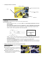
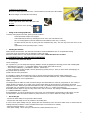
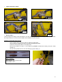
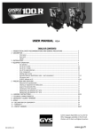
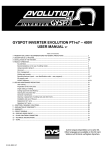
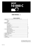
USER'S MANUAL
DC LC
DC LX
TABLE OF CONTENTS
DC LCX
1- PRESENTATION, SECURITY STANDARDS AND GENERAL PRECAUTIONS ...................................... 3
2- DESCRIPTION OF THE MACHINE ............................................................................................................. 3
-
front panel .....................................................................................................................
electronic board .............................................................................................................
rear panel ......................................................................................................................
clamp ............................................................................................................................
4
4
4
4
3- INSTALLATION OF THE MACHINE ............................................................................................................ 5
-
before use .....................................................................................................................
handle, clamp support and earth cable fixing (accessories bag) ..........................................
filling of the cooling liquid tank ........................................................................................
starting the machine .......................................................................................................
5
5
6
6
4- DESCRIPTION OF THE MACHINE WORKING ......................................................................................... 6
-
function of the electronic card ......................................................................................... 6
use of the gun................................................................................................................ 7
use of the pneumatic clamp............................................................................................. 7
5- SAFETY AND MAINTENANCE PRECAUTIONS ......................................................................................... 8
-
training of the user ......................................................................................................... 8
preparation of the parts to be assembled.......................................................................... 8
single point welding ........................................................................................................ 8
use of the under panel arms............................................................................................ 8
ring seals for the arms nuts ............................................................................................. 8
change or setting of X arms............................................................................................. 9
chane or setting of C arms .............................................................................................. 9
types of arms for C clamp ............................................................................................... 10
use of C2 arm ................................................................................................................ 10
change of caps/electrodes ............................................................................................... 11
level and effectiveness of cooling liquid ............................................................................ 11
cleaning or replacement of welding tools .......................................................................... 11
bleeding of the pneumatic filter ....................................................................................... 11
maintenance of the generator.......................................................................................... 11
6- IN CASE OF DEFAULT ........................................................................................................... 12
S102
Mise à jour 21/09/2007
Thank you for your choice ! Before installing and using the product or before maintenance, please read carefully the following safety recommendations in
order to avoid accidents to the users and damage of the welding process.
In any case GYS can be responsible for the damages occurring to persons or things, which derive from the use of the machine in following circumstances :
- Modification or neutralization of safety elements,
- Non-respect of the recommendations written in the manual instruction,
- Modification of the characteristics of the product,
- Use of the accessories, which are different from the ones delivered by GYS,
- Non-respect of the regulations and particular dispositions in the country where the machine is installed.
1 - PRESENTATION
This product has been designed to carry out the following operations in car body workshops :
- Spot welding on metal sheets with a pneumatic clamp,
- Welding of metal sheets with gun,
- Welding of nails, rivets, discs and pins,
- Repair of bumps and impacts (impacts of hail with the option « quick repair”).
GENERALITIES
1. The operators must have followed up an appropriate training.
2. The operation of servicing can only be controlled by qualified technicians.
3. The operator is responsible for respect of the car manufacturer’ recommendations, concerning the protection of electrical and electronic equipments (car
computer, car radio, alarm, air bag, etc…).
4. Before an operation of servicing or repair, the compressed air supply must be cut off and off loaded.
5. The electrodes, arms, and the other secondary conductors can reach a very high temperature and remain hot very long after having stopped the machine.
Be careful : high risk of burns.
6. It is necessary to make a regular preventive maintenance.
ELECTRICITY
Check that the unit ist be connected to the earth coupler and that the connection to the earth is in good condition.
Check that the workbench is connected to the earth coupler.
Make sure that the operator has no contact with the metal parts to be welded without any protection or with wet clothes.
Avoid being in contact with the welding part.
Don’t make spot welding operations in very wet areas or on a wet floor.
Don’t weld with worn out cables. Check that there is no default with the isolation with stripped cables or with loose connections, and that there is no cooling
liquid leak.
Before controlling or repairing, please switch off and disconnect the unit directly from the plug.
EYE AND BODY PROTECTION
1. During the welding process, the operator must be protected from the eventual flashes of the electrical arc with protection clothes like leather gloves,
welding aprons, safety shoes, welding helmets or glasses for filtering radiations and projections. In the same way, during operations of rubbing and
hammering, the operator must wear eye protection.
2. The tightening force of the clamp can reach 550 DaN. Keep away all body parts from the mobile elements to avoid risks of tightening.
3. Don’t wear rings, watches, or jewellery, which are current lead and can create burns.
4. All the protection boards must be in good condition and maintained in place.
Never look at a welding arc without any eye protection.
Protect the environment near the product against projections and reflections.
SMOKES AND GAS
1. Welding operations cause the emission of toxic smokes and harmful metallic dusts. Use the device in a sheltered place equipped with smoke aspirators.
2. The operator must wear an anti smoke mask.
3. The welding material must be degreased and cleaned in order to limit the toxic gas emission during the welding process.
FIRE
1.
2.
3.
4.
5.
Make sure that the sparks won’t cause fire especially near inflammable material.
Check that fire extinguishers are near the operator.
Leave the product in a place with air sniffers.
Don’t weld neither on containers of combustibles and lubricants, even empty, nor on containers with inflammable material.
Don’t weld in an atmosphere full of inflammable gas or fuel steam.
ELECTRO-MAGNETIC COMPATIBILITY
Nearby the spot-welding machine, check that:
- there is no other power supply cable nor control lines, nor phone cables, nor radio or TV reception appliances, nor watches, nor mobile phones, nor
magnetic cards, nor computers nor any other electronic appliance.
- there is in the surroundings (minimum 3 meters of each point of the product) no persons using active medical appliances (pacemakers, acoustic
prosthetics).
Make supplementary protections if there are other products being used in the same environment.
This device has been designed for a use in industrial or professional environment following the norm CISPR11. In a different environment, the
electromagnetic compatibility would be difficult to insure.
2
CE NORM
This device has been designed with respect to the European standards :
- Low Voltage Directive 73/23 EEC dated February 19th 1973 (decree n°95-1081 of 3rd October 1995), by application of
standard EN60204-1..
- Electromagnetic Compatibility Directive 89/336 CEE dated May 3rd 1989.
- Machines under pressure Directive 97/23 CEE dated November 29th 1999.
- Exposition of workers to electromagnetic fields Directive 2004/40/CE dated April 29th 2004, by application of standard PR
EN 50505.
2 – DESCRIPTION OF THE MACHINE
Front panel DC-LX
Compressed air circuit
pressure indicator
Electronic board to
communicate with the
user.
Compressed air pressure
setting reel
Face panel DC-LC
Compressed air circuit
pressure indicator
Electronic board to
communicate with the
user.
Compressed air pressure
setting reel
Front panel DC-LCX
Compressed air circuit
pressure indicator
Compressed air pressure
setting reel
Electronic board to communicate
with the user.
Clamp selection
C clamp / X clamp
3
Front panel electronic board
1 – Sheet thickness
indicator.
2 – Decrement
button for the
various
parameters
3 –Increment button
for the various
parameters
A – Selection of the
presettings for soft steel
sheets welding (clamp
and gun)
B – Selection of the
presettings for coated
sheets welding (clamp
and gun)
H – Modification of
parameters : POWER
and TIME..
C – Selection of the
presettings for HTS /
UHTS sheets welding
(clamp and gun)
G –Data display for the
user
D – ON/OFF switch for
gun cooling
E – Selection of the tool
CLAMP.
Rear panel
Fan with dustproof filter
F – Selection of the tool GUN and
selection of the associated GUN
ACCESSORY.
D curve ON/OFF switch
Pneumatic filter, connection
to the pneumatic network
X clamp (for GYSPOT INVERTER DC.LX or DC.LCX)
Remote sheet type selection
Arms nuts
Clamp closure / welding button
Over opening button
Remote sheet thickness setting
4
C clamp (for the DC.LC or DC.LCX)
Closure / welding
Remote sheet thickness setting
C arm
C arm locking / unlocking
lever
Mobile axis
3- INSTALLATION OF THE MACHINE
Before use
Several verifications are necessary before using the unit to ensure good performance.
Here are the points to check :
Check the electrical line voltage : you must have 400V with a 32 A delayed circuit breaker, curve D (or
fuse of aM type).
Check the cable section which arrives until the connecting plug : it should be 4x6 mm2. If the electrical line
from electrical board is superior to 10m, use a conductor size of 10mm². If you use an electrical extension
cord, use a 6mm² conductor size (10mm² if electrical line + extension cord total length is superior to 10m).
Connect a 3 phase + Earth plug (minimum 32A) on the supply cable.
GYSPOT INVERTER
DC LX
DC-LC
DC-LCX
-
-
Caution : in order to avoid voltage drops which can generate bad welding spots, you must never have
overloaded electrical lines, nor a not large enough conductor diameter, and the mains plugs must not be too
far from the circuit breaker.
If the machine is not sufficiently supplied, it is not possible to ensure a good welding quality.
Check that the air compressed network can deliver a minimum of 7 bars (dry air), then connect the
compressed air network at the rear side of the machine. The machine must not be used on an air compressed
network with a pressure inferior to 3 bars.
Handle, clamp support and earth cable fixing (accessories bag)
X clamp(DC-LX and DC-LCX)
Fix the clamp support on the right side or on the left
side of the machine.
Fix the handle on the right side or on the left side of
the machine in accordance with the position you have
chosen for the clamp support.
Depending on the arms to be used, position the
clamp either thanks to the dedicated hook or thanks
to the clamp hanger (see opposite)
5
C clamp (DC-LC and DC-LCX)
Fix the C clamp support thanks to the 3 screws M6X16 on the left side of the machine
Fix the hanger on the left side of the clamp.
Earth cable ( DC LC / DC-LX / DC LCX)
Fix the copper sheet at the end of the earth cable
Air joint
Fix the air connection on the air filter.
Filling of the cooling liquid tank
To fill the cooling liquid in the tank, please proceed as follows :
Put the pneumatic clamps on its support.
Collect delicately the arms by releasing the screw on the side of aluminium nuts.
Pour out cooling liquid to reach the maximum level indicated on the unit (≈ 30 litres).
Put back correctly the arms in place (until the mechanical stop unit). The neck ring must come close to the
nuts.
Tighten both screws (screwing couple : 15 Nm).
Starting the machine
Switch ON the circuit breaker. The electronic card starts a test and initialisation cycle of the parameters during
10 seconds. At the end of this cycle, the machine is ready to be used.
When the machine starts to work, liquid circulates in the cables. Check that there are no leaks.
4- DESCRIPTION OF THE MACHINE WORKING
Fonction of the electronic board
Choice of language
For a special use, you can change the language (initially in French) by applying the following process when switching ON :
- Simultaneously, press key « 3 » and switch ON the circuit breaker at the back of the unit,
- The message « FRENCH [+] TO CHANGE » appears . Release key 3.
- Select the language (French, English, German, Spanish) by pressing on key 3. Once you have chosen the language, let
the product reboot (5 seconds).
Recall of the last user's parameters
It is possible to retrieve the last data of the user by carrying out the following procedure when switching ON :
Press simultaneously the « H » button and switch ON the circuit breaker behind the unit, until the following message
appears : « Restitution of user’s parameters ».
Cables cooling
The clamps bundle of cables are water cooled and the gun and earth cables are cooled by compressed air. The cooling of
clamps bundle is permanent. The cooling of the gun and earth cables can be permanent or controlled by an internal
temperature sensor. When the gun and earth cables are cold, it is possible to stop the air flow by pressing the « D » button
(green light off). It is possible to force the cooling by pressing on the « D » button (green light on).
A thermal protection allows to stop the using of the unit in case of overheat. The message « GENERATOR OVERHEAT »
or « CABLES OVERHEAT » appears.
Recommendation : In case of an intensive use in gun mode, it is recommended to permanently cool the cables. It is also
recommended to leave the machine switched on, after intensive use, in order to allow the cooling of the cables.
Use of the gun
- Connect the earth clamps to the generator cable terminal.
- Firmly fix the earth clamp as near as possible to the welding area.
In case of mono point welding with gun, always place the earth clamp on the steel sheet which is not in contact with the
welding electrode (so that the current circulates between the 2 steel sheets to be welded).
- Select the GUN tool with the « F » button.
- Mono point welding : choose the type of steel sheets to weld with buttons A, B or C.
6
- Other processes : choose the accessory used with the « F » button.
1 – Withdrawal of impacts
2 – Smoothing of dents
3 – Carbon electrode
4 – Welding of studs
5 – Welding of rivets
6 – Welding of nuts
7 – Cord Welding with the serrated roller
- Select the thickness of the metal sheet to be welded using « 2 » and « 3 » keys. It is possible to change the current and
time parameters by pressing on « H » key and modify with keys « 2 » and « 3 ».
Use of the pneumatic clamps
When you use the pneumatic clamp, always disconnect the earth clamp (used in gun mode) from the vehicle.
For DC-LCX, select the clamp you will use with the switch on the front side.
Clamp choice
C clamp / X clamp
!
DC-LCX : For good operation of the cooling system, it is compulsory that both clamps (C and X) are equipped with
their arms during operation.
X clamp
- Adjust and tighten the arms of the clamp, making sure that both electrodes are perfectly aligned (couple : 15 Nm).
- Adjust the air pressure depending on the arms used (see the tables below and on the unit).
Maximum Locking Pressure
Arms
Maximum pressure
GYS reference (set of 2 arms
L=120 Copper
7 bars
050501
L=220 Copper
8 bars
050518
L=350 over midth Copper
Copper under Fender
8 bars
5 bars
050525
050549
L=440 over midth Aluminium
8 bars
050532
Recommended parameters for soft steel metal sheets :
Sheet Thickness (in mm)
Recommended Pressure (in daN)
Arms Length (in mm)
Air Pressure (in bars)
From 0,4 to 0,8
100 to 200
120
2 to 3
From 0,4 to 0,8
From 0,4 to 0,8
100 to 200
100 to 200
220
440
2 to 4
5 to 7
From 1 to 2
150 to 300
120
3 to 3,5
From 1 to 2
From 1 to 2
150 to 300
150 to 300
220
440
3 to 6
6 to 7
More than 2
300 to 550
120
4 to 7
More than 2
230 to 550
220
6 to 8
- Select the tool CLAMP with the « E » button.
- Choose the type of metal sheet to be welded with the buttons A, B or C.
- Select the metal sheet thickness to be welded with keys 2 and 3. It is possible to change the power
and time parameters by pressing on keys H and and to modify using keys 2 and 3.
C clamp
- Tighten the C-clamp using the locking lever and check that the screw between the arm and the clamp is correctly
tightened.
- Set the air pressure (see the table below and on the unit).
7
Effort de serrage maximum
Arms
Maximum Pressure in bars
GYS reference
C1
8 bars
019140
C2
C3
8 bars
8 bars
019133
019157
C4
8 bars
019164
C5
8 bars
019294
Recommended parameters for soft steel metal sheets :
Sheet Thickness (in mm)
Type of Arm
Air Pressure (in bars)
Locking Pressure (in daN)
From 0,4 to 0,8
C1-C2-C3-C4-C5
3
100 to 200
1 to 2
2 to 3
C1-C2-C3-C4-C5
C1-C2-C3-C4-C5
3,5 to 4
4 to 8
150 to 300
300 to 550
- Select the tool CLAMP with the « E » button.
- Choose the type of metal sheet to be welded with the buttons A, B or C.
- Select the metal sheet thickness to be welded with keys 2 and 3. It is possible to change the power
and time parameters by pressing on keys H and to modify using keys 2 and 3.
WARNING :
The clamps and the gun of the unit are connected to the same current source. This means that when you use one of these
2 tools, there is also power on the second tool. The tool which is not used must therefore be placed on its stand on the
trolley (clamps stand located on the side of the trolley and gun stand located on the T-Shape balancer).
In case these instructions are not respected, severe damage can occur to the generator tools. Sparks and metal projections
can occur (DANGEROUS FOR THE USER).
5- SAFETY AND MAINTENANCE PRECAUTIONS
Training of the user
Operators must have an appropriate qualification for the use of the machine in order to get the best of the unit and to make
satisfying work (e.g. : car-body repair training).
Preparation of the parts to be assembled :
It is essential to clean off and to accost the part to be welded.
In case of a protection application, first verify that it is conducting by testing a sample.
Single point welding
Before repairing a vehicle, check that the car manufacturer authorizes the welding process you have chosen.
Use of under panel arm
Considering the strong locking pressure of the clamp, the air compressed pressure should be lowered to 4 bars.
WARNING : a pressure higher than 5 bars can cause the destruction of the arms set and therefore metal projections that
might cause body damage to the operator.
Ring seals for the arms nuts
Inside the 2 tightening arms nuts (see description of the clamp), there are 2 ring sealss which have to be replaced in case of
leaks or every 6 months. These 2 ring seals are necessary to avoid risks of cooling liquid leaks.
These ring seals have a diameter of d=25, flange=4. During replacement, grease should also be added (ref. 050440).
Change or setting of X arms
When changing the arms, place the clamp on its stand, and proceed as follows :
When the unit is working, press about 2 second on the button E « CLAMPS SYMBOL ». The message CLAMPS
ADJUSTMENT appears. The water circulation stops.
Put the clamps above the water level in the cooling liquid tank.
Take a recipient of about 1 litre to collect the water pouring from the arm.
Screw off the tightening screw of the arms nuts.
Take the arms off and collect the liquid in the arms.
Take the other arms, put some grease all around the arm’s extremity.
Check the presence of the washer (washer D=25, flange of 4) and check its good state.
Put the arms back against mechanical stop. Adjust them so that both electrodes face each other. Then screw
both screws of the arms nuts (couple 15 Nm).
Check the level of cooling liquid.
Press on the button E « clamps symbol », the circulation of the liquid starts again.
8
When you adjust the arms, proceed as follows :
To precisely adjust the arms clamps, it is necessary to close the clamps without the generator making a welding point. In
order to do this, press on the “E” button during about 2 seconds. The message « CLAMPS ADJUSTMENT » appears. By
pressing on the closing trigger on the clamps, you can adjust the arms as no current is supplied by the generator. To come
back to normal mode, press the “E” button again.
WARNING : if the arms are not correctly tightened during the liquid circulation, arms can be ejected from their housings and
may create material or body damages.
Change or setting of C arms:
When changing the arms, place the clamp on its stand, and proceed as follows :
-
When the unit is working, press about 2 second on the button E « CLAMPS SYMBOL ». The message CLAMPS
ADJUSTMENT appears. The water circulation stops.
Unscrew the screw between the arm and the clamp (1).
Disconnect the 2 water pipes (2).
Unscrew the lever on the side of the clamp (3)
Remove the arm form the clamp (Warning : put the screw back onto the arm, to make sure not to lose it) (4).
Take another arm and insert it in the clamp (Warning : don’t forget to remove the screw on the arm).
Screw the screw to assemble arm and clamp.
Screw the lever again.
Check the cooling liquid level
Press again on key “E” (“clamp”), the liquid circulation starts again.
1
2
4
3
9
Types of arms for C clamp :
C2
C1
C3
C4
Use of C2 arm :
This arm requires the change of the short spindle. To do this, follow the process entitled “Changing of the arms of C-clamp”
but using a flat key to un screw the short spindle off and substitute it by the long one.
Replace the short spindle by the long one
-
Take a recipient with a capacity of 100mL to collect the cooling liquid
Unscrew the short spindle off and take it off without forgetting the injector
Collect the cooling liquid (which is in the clamp axis)
Move the long injector to center it in the clamp axis (WARNING: bevelled side outside), then put it inside
manually (1).
Place the short spindle and screw it on the clamp axis (couple 15Nm) (2).
Long spindle
Long injector
1
Short spindle
Type of spindles :
Short injector
2
Short spindle : CN 1, CN3 et CN4
Long spindle : CN2
10
▪
▪
▪
▪
Change of caps/electrodes :
To guarantee a sufficient spot welding, it is necessary to replace the caps every 200 spots.
It is forbidden to grind the caps.
Several combinations are possible
Use some grease to place caps (ref. 050440)
Level and effectiveness of cooling liquid
The level of cooling liquid is important for the good functioning of the unit. It must always be between the minimum and
the maximum indicated on the trolley.
You have to check with an adequate tool the quality of the cooling liquid. If this one is no more efficient, replaced it.
Replace the cooling liquid every 2 years.
Never add water. Always add cooling liquid.
Cleaning or replacement of welding tools Nettoyage ou remplacement des outils de soudage et autres
All welding tools are depreciate during their use. However all tools must stay clean in order to get the best of the unit.
When you use the unit in pneumatic clamp mode, check the good state of the CAPS electrodes (flat, rounded or bevelled). If
this is not the case, clean them with sandpaper (fine grain) or replace them (see reference on the unit).
For a use on gun mode, it is necessary to check the state of the tools : stars, monopoint electrode, carbide electrode, … and
if they look in bad conditions clean or replace them.
The anti-dust filter at the back of the unit must regularly be clean to avoid the overheating of the generator.
Bleeding of the pneumatic filter
Regularly bleed the dehumidifier filter placed on the rear side of the unit.
Maintenance of generator
The maintenance and the repair of the current generator must be done by an appointed and GYS trained technician. All
intervention done by an other person will cancel the warranty conditions. GYS cannot be responsible for damages or
accident which happen subsequently to this intervention.
6- IN CASE OF DEFAULT :
If the unit activates the circuit breaker of protection, check that you have the right calibre and the correct circuit breaker
(curve D mandatory).
If the unit at the starting indicates the message « fault power supply », 3 defaults are possible :
A neutral can be connected instead of a phase.
A phase is missing on the plug.
If the message appears during 5 seconds after the end of the welding point, the electrical line is bad.
(excessive conveyance loss )
If after verification and solving the problem persist, contact your GYS retailer.
If the unit indicates « CAPTOR FAULT », contact your GYS retailer.
11