1
ports three and four on the data logger. Power and communication requirements for each instrument
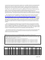
and sensor are discussed below. CR1000 channel assignments are shown in Table 1.
Table 1: VFD case study Campbell Scientific CR1000 data logger channel assignments.
Channel
1
2
3
4
5
6
P1
COM1
COM2
COM3
COM4
Source
Flow meter
Inlet pressure transducer
Discharge pressure transducer
Pivot point pressure transducer
Pivot end pressure transducer
Corner arm pressure transducer
Tachometer
Power panel power meter
VFD input power meter
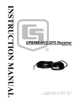
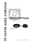
Pivot end GPS
Corner arm GPS
Parameter
Flow rate
Inlet pressure
Discharge pressure
Pivot point pressure
Pivot end pressure
Corner arm pressure
Pump speed
Supply power
VFD power
Pivot end position
Corner arm position
Signal type
Units
Range
4-20 ma
GPM
0-1500
0.5-5.5 VDC
PSI -14.7 to 15
0-5 VDC
PSI
0-100
4-20 ma
PSI
0-100
4-20 ma
PSI
0-100
4-20 ma
PSI
0-100
0-5 VDC
RPM
0-2000
RS485/RS232 kW, kWh, Amps, V, PF
various
RS485/RS232 kW, kWh, Amps, V, PF
various
RS232
northing/easting
various
RS232
northing/easting
various
Flow meter
A GE Panametrics PT878 ultrasonic flow meter will be used to record system water flow rate data using
the CR1000 data logger at the same time interval as all the other test parameters. A 4-20 ma output
cable, supplied by GE Panametrics (p/n 704-609), will be required to transfer the instantaneous flow rate
data to the data logger.
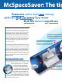
A McCrometer M0308 McPropeller flow meter with McCrometer McSpaceSaver FS100 flow
straightener vanes will be used on systems that do not have the required pipe length before and after the
ultrasonic flow meter to ensure the required ±2% accuracy required. A McCrometer EA631 pulse
transmitter will be required to transmit the signal to the CR1000 data logger.
Power meters
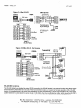
Two Acuvim II power meters will be used to monitor power quality parameters. Data recorded will
include volts, amps and power factor for each leg of the 3-phases, kilowatts and kilowatt hours for each
test circle. MODBUS protocol will be used to transmit data to the data logger from the Acuvim II meters.
The data output from the power meters will be transferred using RS485 MODBUS protocol and converted
to RS232 protocol using two BlackBox IC820A converters connected to COM ports 1 and 2 on the CR1000
data logger. Power for the meters will be supplied from a 120 VAC source or from the lines being
monitored. The RS485/RS232 converters must be powered from the 12 V Power out connection of the
CR1000 to ensure a common ground. The Rx Com wire (C2 on the CR1000 wiring panel) will be connected
to the RS232 pin 2 and the Tx Com wire will be connected to RS232 pin 3. A ground must be connected
from the CR1000 Power out connection on the CR1000 wiring panel to the RS232 pin 5 to ensure there is
a common ground.
Initial communication with the Acuvim II was unsuccessful. MODBUS protocol has not been used
previously at the Agtech Centre for data collection. During the troubleshooting process, it was found that,
although MODBUS is a standard communication protocol, it requires specific software (above), to analyse
the data available from the Acuvim II. Many calls were made to suppliers for information and the
procedure to resolve the communication problem. Finally, one suggested downloading a tool to display
the data to ensure the communication settings were correct and to determine the actual format of the
data. A demo version of ModScan32 (WinTECH.com) was downloaded and used to confirm the
communication settings and the register data documented in the Acuvim II User's Manual. Many possible
Page 4 of 14