1
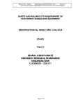
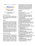
Hart Scientific
5901 Series
Triple Point of Water Cells
User’s Guide
Rev. 580501 ENG
Limited Warranty & Limitation of Liability
Each product from Fluke’s Hart Scientific Division (“Hart”) is warranted to be
free from defects in material and workmanship under normal use and service.
The warranty period is one year for the TPW Cell. The warranty period begins
on the date of the shipment. Parts, product repairs, and services are warranted
for 90 days. The warranty extends only to the original buyer or end-user customer of a Hart authorized reseller, and does not apply to fuses, disposable batteries or to any other product which, in Hart’s opinion, has been misused,
altered, neglected, or damaged by accident or abnormal conditions of operation
or handling. Hart warrants that software will operate substantially in accordance with its functional specifications for 90 days and that it has been properly recorded on non-defective media. Hart does not warrant that software will
be error free or operate without interruption.
Hart authorized resellers shall extend this warranty on new and unused products to end-user customers only but have no authority to extend a greater or different warranty on behalf of Hart. Warranty support is available if product is
purchased through a Hart authorized sales outlet or Buyer has paid the applicable international price. Hart reserves the right to invoice Buyer for importation
costs of repairs/replacement parts when product purchased in one country is
submitted for repair in another country.
Hart’s warranty obligation is limited, at Hart’s option, to refund of the purchase
price, free of charge repair, or replacement of a defective product which is returned to a Hart authorized service center within the warranty period.
To obtain warranty service, contact your nearest Hart authorized service center
or send the product, with a description of the difficulty, postage, and insurance
prepaid (FOB Destination), to the nearest Hart authorized service center. Hart
assumes no risk for damage in transit. Following warranty repair, the product
will be returned to Buyer, transportation prepaid (FOB Destination). If Hart determines that the failure was caused by misuse, alteration, accident or abnormal
condition or operation or handling, Hart will provide an estimate or repair costs
and obtain authorization before commencing the work. Following repair, the
product will be returned to the Buyer transportation prepaid and the Buyer will
be billed for the repair and return transportation charges (FOB Shipping Point).
THIS WARRANTY IS BUYER’S SOLE AND EXCULSIVE REMEDY AND
IS IN LIEU OF ALL OTHER WARRANTIES, EXPRESS OR IMPLIED, INCLUDING BUT NOT LIMITED TO ANY IMPLIED WARRANTY OF
MERCHANTABLILTY OR FITNESS FOR A PARTICULAR PURPOSE.
HART SHALL NOT BE LIABLE FOR ANY SPECIAL, INDIRECT, INCIDENTAL. OR CONSEQUENTIAL DAMAGES OR LOSSES, INCLUDING
LOSS OF DATA, WHETHER ARISING FROM BREACH OF WARRANTY
OR BASED ON CONTRACT, TORT, RELIANCE OR ANY OTHER
THEORY.
Since some countries or states do not allow limitation of the term of an implied
warranty, or exclusion or limitation of incidental or consequential damages, the
limitations and exclusions of this warranty may not apply to every buyer. If any
provision of this Warranty is held invalid or unenforceable by a court of compe-
tent jurisdiction, such holding will not affect the validity or enforceability of
any other provision.
Fluke Corporation
Hart Scientific Division
799 E. Utah Valley Drive American Fork, UT 84003-9775 USA
Phone: +1.801.763.1600
Telefax: +1.801.763.1010
Email: [email protected]
www.hartscientific.com
Subject to change without notice. Copyright © 2005 Printed in USA
Table of Contents
1 Before You Start . . . . . . . . . . . . . . . . . . . . . . . . . . 1
1.1
Symbols Used . . . . . . . . . . . . . . . . . . . . . . . . . . . . 1
1.1.1
1.1.2
Warnings . . . . . . . . . . . . . . . . . . . . . . . . . . . . . . . . . . . . . 2
Cautions . . . . . . . . . . . . . . . . . . . . . . . . . . . . . . . . . . . . . 2
2 Introduction . . . . . . . . . . . . . . . . . . . . . . . . . . . . 5
3 Specifications . . . . . . . . . . . . . . . . . . . . . . . . . . . . 9
4 Freezing an Ice Mantle in the TPW Cell . . . . . . . . . . . . 11
4.1
4.2
Preparations . . . . . . . . . . . . . . . . . . . . . . . . . . . . . 11
Freezing . . . . . . . . . . . . . . . . . . . . . . . . . . . . . . . 11
4.2.1
4.2.2
4.2.3
4.3
Dry Ice Freezing Process . . . . . . . . . . . . . . . . . . . . . . . . . . . . 11
The Heat Pipe Freezing Process . . . . . . . . . . . . . . . . . . . . . . . . 12
Metal Pre-cooled In Liquid Nitrogen Freezing Process . . . . . . . . . . . . 14
The Inner Melt. . . . . . . . . . . . . . . . . . . . . . . . . . . . 14
5 Maintenance and Life-Time of a TPW Realization . . . . . . 15
6 Using the Cell . . . . . . . . . . . . . . . . . . . . . . . . . . . 17
7 Isotopic Composition . . . . . . . . . . . . . . . . . . . . . . . 19
8 Care of Your TPW Cell . . . . . . . . . . . . . . . . . . . . . 23
9 REFERENCES . . . . . . . . . . . . . . . . . . . . . . . . . . 25
i
Figures
Figure 1
Figure 2
ii
Triple point of water cell designs and dimensions . . . . . . . . . . . . 6
Freeze an ice mantle using a “Quick Stick” . . . . . . . . . . . . . . . 13
Tables
Table 1
International Electrical Symbols . . . . . . . . . . . . . . . . . . . . . 1
iii
1 Before You Start
Symbols Used
1
1.1
Before You Start
Symbols Used
Table lists the International Electrical Symbols. Some or all of these symbols
may be used on the instrument or in this manual.
Table 1 International Electrical Symbols
Symbol
Description
AC (Alternating Current)
AC-DC
Battery
CE Complies with European Union Directives
DC
Double Insulated
Electric Shock
Fuse
PE Ground
Hot Surface (Burn Hazard)
Read the User’s Manual (Important Information)
Off
On
1
5901 Series Triple Point of Water Cells
User’s Guide
Symbol
Description
Canadian Standards Association
OVERVOLTAGE (Installation) CATEGORY II, Pollution Degree 2 per IEC1010-1 refers to the level of Impulse Withstand Voltage protection provided. Equipment of
OVERVOLTAGE CATEGORY II is energy-consuming equipment to be supplied from
the fixed installation. Examples include household, office, and laboratory appliances.
C-TIC Australian EMC Mark
The European Waste Electrical and Electronic Equipment (WEEE) Directive
(2002/96/EC) mark.
1.1.1
Warnings
Always use extreme care when using liquid nitrogen. Contact with liquid nitrogen can cause frost bite or severe freezer burns.
Use extreme caution when using dry ice. Contact with dry ice can cause frost
bite or severe freezer burns.
1.1.2
Cautions
Read section entitled “Care Of Your TPW Cell” before removing the cell from
the case. Incorrect or improper handling of the cell can damage or break the
cell.
DO NOT shake the cell.
DO NOT invert the cell too fast, as the cell can break due to the “water hammer” (explained in Section 8 “Care of Your TPW Cell”).
If the cell does not produce a water hammer, the cell may be broken even
though there are no visible cracks.
DO NOT allow the entire cell to freeze, as the cell will break.
Avoid the formation of an ice bridge from the reentrant well across the surface
to the outer glass cylinder of the cell while freezing the ice mantle. This may
cause sufficient pressure to break the glass.
While freezing the ice mantle, the mantle should never become so thick that it
comes in contact with the outer glass shell or the cell will break.
The Cell and Quick Stick (if used) need to be well supported during the freezing process, or the cell may be damaged or broken.
DO NOT drop probes into the reentrant well of the cell. The cell and/or probe
will be damaged or broken.
2
1 Before You Start
Symbols Used
It is suggested that the TPW cell be kept in the vertical position during
transportation.
The cell must be transported at temperatures above 0°C.
Avoid vibration and jarring during transportation. The effect of the water hammer can break the cell.
Store the cell in temperatures above 0°C.
DO NOT allow the water in the cell to freeze too quickly. Rapid freezing of the
water in a TPW cell will break the cell.
3
2 Introduction
2
Introduction
The temperature of the TPW is the intrinsic temperature of pure water with the
three phases of water, ice and water vapor in thermal equilibrium. The temperature of the TPW, 273.16K (0.01°C), is 0.01°C above the melting point of ice
(the ice point). The ice point was historically one of the defining fixed points of
the Thermodynamic Temperature Scale and the International Temperature
Scale (ITS-27 and ITS-48). The equilibrium temperature of three phases of a
pure material is unique. The equilibrium of three phases of a pure material can
only exist at a unique pressure. Whereas the equilibrium temperature between
two phases (i.e. melting point and boiling point) varies with pressure. Therefore, a special pressure must be assigned to the melting point or boiling point,
which is usually standard atmospheric pressure (101.325 kPa).
The triple point of water (TPW) is the only thermometric fixed point used in
definitions of both the thermodynamic temperature and the international temperature scale [1-3]. The unit of thermodynamic temperature, Kelvin, is defined
as the fraction 1/273.16 of the thermodynamic temperature of the TPW. It is
also a defining fixed point on the International Temperature Scale of 1990
(ITS-90). According to the ITS-90, the temperatures between 13.8033 K and
961.78°C are determined in terms of the ratio of the resistance at a temperature
T (R(T90)) and the resistance at the TPW (RTPW)of a standard platinum resistance thermometer (SPRT). The ratio, W(T90) is:
W(T90) = R(T90) / RTPW (1)
The Triple Point of Water Cell is an important instrument in temperature calibration labs. TPW cells are the most commonly used and hence one of the most
important temperature fixed points. The triple point of water temperature is the
most reliable and repeatable temperature point available.
Room pressure, desolved gases in water (especially CO2), and other factors
have detectable effects on the equilibrium temperature between water and ice.
Therefore, it is very difficult to obtain an expanded uncertainty of 0.1 mK for
the ice point. Although, it is very easy to obtain an expanded uncertainty of 0.1
mK for the TPW. The water in an ice point apparatus is easily contaminated by
its surrounding environment, but the sealed TPW cell protects the water in the
cell from contamination for many years. For these reasons, in 1954, CGPM
(General Conference of Weights and Measures) adopted the TPW as the sole
point defining the unit of Thermodynamic Temperature instead of the combination of the ice point and the boiling point of water. This is similar to the method
proposed by the famous physicist W. T. Kelvin in 1848.
In order to accommodate the broad application of the TPWs, Hart Scientific has
developed a series of TPW cells, including Models 5901D-G, 5901A-G,
5901B-G, 5901C-G, 5901D-Q, 5901A-Q, and 5901C-Q (Figure 1). Hart Scientific TPW cells and technology make it easy to realize the TPW. All Hart Scientific TPW cells constructed with a high-quality Pyrex envelope, or fused silica
envelope are described in this User Manual. The Variations in the isotopic content of naturally occurring water can cause detectable differences in the TPW
5
5901 Series Triple Point of Water Cells
User’s Guide
temperature. The isotopic composition of water in Hart TPW cells is substantially the same as one of Standard Mean Ocean Water. We will discuss this issue in more detail in the manual.
Model 5901D-G and 5901D-Q Cell are of the design used by national temperature labs around the world. This design has a wide mouth to facilitate the use of
crushed dry ice to freeze the mantle. The rubber foot allows the cell to rest on
the bottom surface of a Dewar vessel when maintained in an ice bath or holding
fixture for extra stability and protection while the cell is in use. The shell material of the 5901D-G is borosilicate glass and the shell material of 5901D-Q is
fused silica glass.
Model 5901A-G and 5901A-Q Cell are designed after the original NBS cell
with a glass support arm. While the arm does not impact performance in any
13.6 mm
12 mm
14.4 mm
420 mm
265 mm
420 mm
265 mm
265 mm
265 mm
420 mm
450 mm
12 mm
50 mm
5901A-G/Q
60 mm
60 mm
60 mm
30 mm
5901C-G
5901C-Q
5901D-G/Q
5901B-G
Figure 1 Triple point of water cell designs and dimensions
6
118 mm
180 mm
8 mm
2 Introduction
way, some users prefer this design because it facilitates lifting and carrying the
cell. The arm can be used as a hook for supporting the cell in an ice bath or
used as a McLeod gauge for a strictly qualitative check of trapped air in the
cell. The shell material of the 5901A-G is borosilicate glass and the shell material of the 5901A-Q is fused silica glass.
Model 5901B-G Cell is a smaller cell that is easy to handle, accommodates
shorter sensors, and can be maintained in an automatic maintenance device,
such as a Hart Scientific Model 9210. Despite this cell’s diminutive size, it is
made with the same materials and technology used to make larger cells. The
5901B has an expanded uncertainty of 0.0002°C and a reentrant well diameter
of 8 mm. The shell material of 5901B-G is borosilicate glass.
Model 5901C-G and 5901C-Q cell are identical to models 5901-G and 5901-Q
cells with the exception of the reentrant well diameter, which is 13.6 mm and
14.4 mm respectively, rather than the standard 12 mm. The larger reentrant well
diameter is designed to accommodate larger diameter thermometers. The shell
material of the 5901C-G is borosilicate glass and the shell material of the
5901C-Q is fused silica glass.
Water impurities and remnant gas are the two primary sources of error for the
TPW cell; therefore Hart Scientific cells are designed to minimize the effects of
these two errors. Both factors lower the equilibrium temperature within the cell.
A higher equilibrium temperature in an inter-comparison usually indicates a
higher quality cell.
High-quality borosilicate glass and fused silica glass are used in the construction of the shell material for TPW cells. The contamination rate of impurities
from (or through) the glass into water is extremely low for these types of glass.
The TPW cell must be assembled with scrupulous attention to the requirement
that the water remain free of impurities. Meticulous cleaning of all parts is extremely important in the manufacture of TPW cells.
Recent research [13] shows that a decrease of 4 microK per year has been observed in borosilicate glass TPW cells due to the dissolution of glass of the cell.
The borosilicate glass may be a less than ideal container as it is the most likely
source of the contamination elements. As a result of this concern, Hart has introduced TPW cells with fused silica glass containers. The fused silica glass
may be a more ideal container material for a TPW cell than borosilicate glass.
More research results may be reported.
7
3 Specifications
3
Specifications
5901A-G
5901A-Q
5901C-G
5901C-Q
5901D-G
5901D-Q
5901B-G
Expanded Uncertainty (k=2)
< 0.0001 °C
< 0.0002 °C
Reproducibility
0.00002 °C
0.00005 °C
Dimensions
50 mm OD
12 mm ID
450 mm long
Immersion Depth (water
surface to well bottom)
Material
60 mm OD
13.6 mm ID
420 mm long
60 mm OD
14.4 mm ID
420 mm long
265 mm
Borosilicate
Glass
Fused Silica
(Quartz)
Borosilicate
Glass
18O
VSMOW
Effect of devaiation from
VSMOW
30 mm OD
8 mm ID
180 mm long
118 mm
Fused Silica
(Quartz)
Water Source
DVSMOW
60 mm OD
12 mm ID
420 mm long
Borosilicate
Glass
Fused Silica
(Quartz)
Borosilicate
Glass
Ocean
±10‰ (±1%)
±20‰
±1.5‰ (±0.15%)
±3‰
±7µK
±14µK
9
4 Freezing an Ice Mantle in the TPW Cell
Preparations
4
Freezing an Ice Mantle in the TPW Cell
CAUTION: DO NOT shake the cell or invert the cell vigorously.
To realize the triple point of water temperature, an ice mantle must be formed
from the reentrant well outward.
4.1
Preparations
It is important that the reentrant well is cleaned and dried before attempting a
freeze of the cell. If this precaution is not taken, water inside the reentrant well
will freeze during the mantle formation, creating a less uniform mantle which
will not last as long. A drop of alcohol in the bottom of the reentrant well before freezing will help prevent ice formation from moisture which may be introduced during the process. Remove any foreign material from the outside of
the cell to prevent contamination of the bath. In order to provide more uniform
mantles and reduce coolant required for freezing, pre-chill the cell by immersing it into an ice bath or maintenance bath until it is no more than a few degrees
above the ice point.
4.2
Freezing
The cell should be frozen by refrigerating the inside of the reentrant well so
that water freezes from the reentrant well outward to form a mantle of ice
around the well. A variety of refrigeration methods are used to freeze a cell,
such as refrigerated cold fingers, heat pipes, LN2 chilled rods and dry-ice.
4.2.1
Dry Ice Freezing Process
A simple and fast method of freezing an ice mantle is to pour crushed Dry Ice
(solid CO2) directly into the dry reentrant well. Support the cell during freezing
in a rack which will prevent breakage but allow complete visibility of the cell.
Use dry ice that is ground or crushed to 2 mm diameter granules, which is the
consistency of snow. Introduce small amounts into the “dry” well until a mantle
is formed at the bottom and then introduce more dry ice until the level is near
the top of the cell. As the dry ice sublimates, continue to refill the reentrant
well so that the level is maintained at the water level. If the dry ice level becomes too low before more is added, the mantle may crack, which will require
additional annealing time. Formation of an ice bridge from the reentrant well
across the surface to the outer glass cylinder of the cell while freezing the ice
mantle may cause sufficient pressure to break the glass. The bridging can be
prevented by warming that portion of the cell with the hand while shaking it
gently sideways to agitate the surface of the water and allow it to wash over the
ice. The mantle should never become so thick that it comes into contact with
the outer glass or breakage could occur. In the vertical position, the mantle will
appear larger than it actually is due to the magnification created by the cylindri11
5901 Series Triple Point of Water Cells
User’s Guide
cal container and the water. If the cell is carefully inverted, the true mantle size
can be observed through the portion of the cell containing only vapor. This procedure should only be performed while the mantle is still attached to the
reentrant well. When the ice mantle becomes sufficiently thick (4 to 10 mm
with at least 5 mm at the bottom) the cell may be carefully moved to the maintenance bath to evaporate the remaining dry ice. Allow the mantle to anneal for
at least two days to remove the strains, since strains in the ice may depress the
actual triple point temperature about 0.2 mK. Applications that do not require
as stringent a level of accuracy will not require this delay. If the mantle cracks,
it takes at least two days to anneal the mantle.
4.2.2
The Heat Pipe Freezing Process
Hart Scientific has developed a “Quick Stick” to facilitate the formation of an
ice mantle with greater ease. Please refer to Model 2031 Quick Stick User’s
Guide for details. The instructions for use of the “Quick Stick” in the formation
of an ice mantle are as follows (Figure 2):
1.
Dry ice is broken into small chunks (less than ¼ inch) appropriate for fitting into the cup.
2.
The TPW reentrant well is dried with alcohol and a ¼ inch of alcohol is
placed into the bottom. Next approximately 2 cc of finely crushed dry ice
is dropped into the bottom of the reentrant well. This helps start the
freeze process and prevents super cooling of the water. A small formation of ice is frozen onto the end of the reentrant well initially before the
heat pipe is inserted, which helps thicken the ice mantle at the bottom.
3.
The dry ice is loaded into the Quick Stick cup and the spaces are filled
with ethanol (approximately 100ml). The Quick Stick must be cooling
before inserting it into the TPW. Once the cooling cycle has begun, insert
it to the bottom of the reentrant well, the radius at the bottom helps center it in the well.
4.
After the Quick Stick is inserted carefully into the cell, the gap is filled
with ethanol until it is a little below the water level in the cell (about 1
cm). This helps to prevent ice from bridging across the top during mantle
formation. A special heat sink is provided that fits around the TPW cell
that also helps prevent bridging. Slide the heat sink onto the cell up to
the level of the water. Room heat is absorbed and transferred to the water
at the surface. Adjust the centering bushing until the heat pipe is centered
in the reentrant well. The cell and Quick Stick need to be well supported
during this process. Care must be taken not to break the reentrant well
during this process or the cell will be ruined. The cell and Quick Stick
must be supported separately. The Hart Scientific model 2067-P support
kit is available for this purpose.
The freezing process takes care of itself beyond this point. Be sure that there is
no ice bridging at the top. One fill of dry ice forms a good mantle in 40 to 60
minutes.
12
4 Freezing an Ice Mantle in the TPW Cell
Freezing
Dry Ice and Alcohol
Centering Bushing
Heat Sink and Strap
Alcohol (1 cm below water)
Ice Mantle
TPW Cell
Figure 2 Freeze an ice mantle using a “Quick Stick”
13
5901 Series Triple Point of Water Cells
User’s Guide
WARNING: Always use extreme care when using liquid nitrogen. Contact
can burn skin or damage eyes.
4.2.3
Metal Pre-cooled In Liquid Nitrogen Freezing Process
Pre-cool a few metal rods in liquid nitrogen. Insert the pre-cooled metal rods
into the heat transfer liquid in the reentrant well successively. Several insertions
will be needed to form an adequate ice mantle.
4.3
The Inner Melt
A very pure ice water interface surrounding the reentrant well is formed by
melting a thin layer of ice next to the well. This interface is referred to as the
“inner melt”. The inner melt is formed first by pouring a small amount of
pre-cooled water or alcohol (below 2°C) into the reentrant well to a level just
above the top of the ice mantle. A glass rod, at room temperature, is then inserted into the reentrant well. The glass rod is left in place long enough, a few
seconds, to melt the ice mantle free from the reentrant well. Test that the mantle
is free by gently rotating the cell and observing that the mantle freely rotates
about the axis of the reentrant well. If the mantle does not rotate, warm the rod
to room temperature and repeat the process. The inner melt should be done
each time the cell is used, and the test for the existence of a free mantle should
be carried out regularly during the course of a use of the Cell. Once the mantle
has been aged and the ice water interface created, the triple point of water cell
is ready to make measurements.
14
5 Maintenance and Life-Time of a TPW Realization
5
Maintenance and Life-Time of a TPW
Realization
After a short period of time, the ice mantle will reattach to the reentrant well.
Pressure can build up in this layer and observed temperatures can be low by as
much as 0.0001°C. The mantle must, of course, again be freed by the temporary insertion of a warm rod in the well as described in section 4.3.
The cell should be prepared at least two days prior to its use. The equilibrium
temperature in a TPW cell is a little low (0.0005°C) immediately after freezing.
The reason for this low initial temperature and the subsequent gradual increase
during one or two days to a steady value is believed to be connected with structural strains that are produced when the ice is first frozen. Presumably, the
strains are relieved with time as the ice anneals. The magnitude of the lower
initial temperature and the rate of increase to a steady temperature value is dependent upon the specific technique that is employed in freezing the cell.
A TPW cell with an ice mantle can be preserved for a few months in a well
controlled bath or in a Dewar filled with crushed ice with a plastic container between the Dewar and the TPW cell. The temperature uniformity and stability of
the bath used to maintain TPW cells should be ± 0.003°C or better.
Hart’s 7012 and 7312 baths are designed for this purpose. The 7012 bath can
accommodate up to four TPW cells and the 7312 bath up to two. According to
our experience, the bath temperature should be set at about 0.003°C below the
TPW (about 0.007°C) in order to maintain the TPW for a few months. If the
bath temperature is too low, more water in the cell will freeze. If the bath temperature is too high, the ice mantle in the cell will melt gradually. During the
first month a bath is used to maintain TPW cells, the ice mantle should be
checked daily. Adjust the bath set temperature a little if necessary to obtain the
optimal maintenance situation. If an ice bridge is found across the top surface
of water in the cell, it must be melted immediately. Otherwise the pressure created from water freezing on the surface might break the cell. After initial adjustments of the bath, the TPW cells in the bath can be used for a few months
with little care.
Hart’s 2028 Dewar can be used to maintain TPW cell. When a TPW cell is
maintained in Dewar with crushed ice, ice will form on the surface of the water
in the cell as a result of heat transferred via the vapor to the cold glass, which is
often at 0°C. When a cell is not disturbed for several days, the ice will freeze
completely across the top surface and must be melted back (e.g. by warming
with the hands) before the cell ruptures. Care must be taken to warm the water
as little as possible so as not to melt too much of the mantle. The above effects
are much reduced by insulating the cell from the ice bath. As mentioned above,
this can be done by using a plastic container with foam spacers to ensure that
there is an air gap of about 1 cm between the cell and the container wall. A cell
stored in this way can be used for many months with very little attention beyond maintaining the ice bath.
15
6 Using the Cell
6
Using the Cell
The following recommendations will improve accuracy and extend the life and
usefulness of the cell.
Shock Protection
By placing a small foam rubber sponge in the bottom of the re-entrant well, the
shock created when placing the SPRT or other sensor into the re-entrant well
will be reduced.
Heat Transfer Medium
There should be fluid in the re-entrant well such as water or alcohol to act as a
heat transfer medium from the ice and water interface to the thermometer in the
well. A sufficient volume of fluid must be in the re-entrant well to bring the
level above that of the cell water when the thermometer is inserted. If desired, a
brass or aluminum bushing about 5 cm long may be used to increase the thermal conduction between the thermometer and the ice water interface, which
will also reduce external self heating of the thermometer.
Thermometer Pre-cooling
The thermometer should be pre-cooled for at least 5 minutes before insertion to
avoid excessive melting of the ice mantle. Insertion into the maintenance bath
or separate ice bath is an excellent way to pre-cool the thermometer. The Hart
Scientific maintenance bath Models 7012, 7312, and ice bath Dewar Model
2028 have holes for pre-cooling.
Ambient Radiation
Ambient room radiation to the thermometer can elevate its temperature by several tenths of a milli-Kelvin above the temperature of the inner melt even when
the cell is completely packed in ice. To provide sufficient radiation shielding
and to insure that the desired accuracy is obtained, use an opaque, insulated,
covered container.
Hydrostatic Pressure Effects
At a depth l meters below the liquid surface (where the true triple point temperature exists) the equilibrium temperature t at the solid-liquid interface is given
by t = A + Bl, where A = 0.01°C and B = -7.3 X 10⁻⁴ m-1 °C. Since the thermometer sensor is not located at the surface, the effects of hydrostatic pressure
must be corrected. For example, in the case of an SPRT with the sensor at 242
mm below the surface, the correction is computed as shown below:
T = 0.01°C + (-7.3 X 10⁻⁴ m-1 °C)x 0.242m = 0.00982334°C
17
7 Isotopic Composition
7
Isotopic Composition
Variations in the isotopic content of naturally occurring water can cause detectable differences in the TPW temperature. A difference as large as 0.25 mK in
TPW temperatures has been found between ocean water and water obtained
from melted polar ice. Neither the SI definition of the Kelvin (the unit of the
thermodynamic temperature as 1/273.16 of the thermodynamic temperature of
the triple point of water) nor the official ITS texts (ITS-90 and IPTS-68) specify the isotopic composition of water for the TPW. Some suggest that documents published by BIPM, such as “Supplementary Information for the
International Temperature Scale of 1990” [4] and “Supplementary Information
for the IPTS and EPT-76” specify that the isotopic composition of water for
TPW should be substantially the same as ocean water.
The followings excerpts are taken directly from “Supplementary Information
for the International Temperature Scale of 1990”:
“An operating triple-point cell contains ice, water, and water vapor, all of high
purity and of substantially the isotopic composition of ocean water.”
“Variations in the isotopic content of naturally occurring water can give rise to
detectable differences in the triple-point temperature. Ocean water contains
about 0.16 mmol of 2H per mole of 1H, 0.4 mmol of 17O, and 2 mmol of 18O
per mole of 16O; this proportion of heavy isotopes is almost never exceeded in
naturally-occurring water. Continental surface water normally contains about
0.15 mmol of 2H per mole of 1H; water coming from polar snow or glacial ice
may occasionally contain as little as 0.1 mmol of 2H per mole of 1H.
The purifying of water may slightly modify its isotopic composition (distillation normally entails a decrease in the 2H content), and the isotopic composition at an ice-water interface is very slightly dependent on the freezing
technique.
A decrease of 10 µmol of 2H per mole of 1H corresponds to a decrease of temperature of the triple point of about 40 µK; this is the difference between the
triple points of ocean water and the normally occurring continental surface water. An extreme, and quite atypical, difference in the triple-point temperatures
of naturally-occurring water is about 0.25mK and is that between sea water and
water obtained from melted polar ice.”
Recently D. R. White et al has made a deep investigation on the effect of isotopic content on triple-point temperature of water [12]. The follows are some information from White’s paper:
The international science community, through the International Atomic Energy
Agency, uses a defined Standard Mean Ocean Water (SMOW) as a point of
reference
for studies in the isotopic composition of waters. Measurements of isotopic
composition are made with respect to V-SMOW (Vienna-SMOW) and SLAP
(Stand Light Antarctic Precipitation), two standard reference materials (waters)
19
5901 Series Triple Point of Water Cells
User’s Guide
that span the isotopic range of naturally occurring waters. Absolute measurements of the isotope ratios for V-SMOW give:
(D/1H)V-SMOW = 0.00015576(5),
(18O/16O)V-SMOW = 0.00200520(45),
and
(17O/18O)V-SMOW = 0.0003799(8).
Variations in isotope ratios are conventionally reported as deviations from
V-SMOW:
δ18O = [(18O/16O)sample – (18O/16O)V-SMOW ]/ (18O/16O)V-SMOW ,
and similarly for δD and δ17O. Usually the results are in the parts-per-thousand
range so are expressed as per mil (per thousand, ‰).
For isotopic compositions near V-SMOW, the effect of the isotopes can be approximated by a liner function of the delta values:
Tmeas = TV-SMOW +ADδD + A17Oδ17O +A18Oδ18O
There are few measurements of the isotopic depression constants. The most
precise are by Kiyosawa (1991) who measured the melting point elevation of
samples of water enriched with D and 18O. The depression constants were
found from Kiyosawa’s data to be: AD=628 ± 6 µK and A18O=641 ± 23µK.
The value of A17O is inferred as 57 µK.
The delta values δD, δ17O, and δ18O for precipitation (meteoric waters) are
highly correlated. Approximate relationships are δD=8*δ18O+0.01, and 1+δ17O
= (1+δ18O)0.528. Therefore, the temperature correction can be predicted from
measurements of δD only according to:
(Tmeas - TV-SMOW) µK = 712 X δD – 0.8
A great effort has been made at Hart to reduce the uncertainty of TPW due to
variations in the isotopic composition of water. We try to make the final isotopic composition of water in a Hart TPW as close to V-SMOW as possible. Because the isotopic composition of water will change during each operation of
the manufacturing process (distill and degas), we should pay attention not only
to the isotopic composition of the original water, but also to the manufacturing
technique. Now we are glad to announce that the isotopic composition of water
in Hart TPW cells is nearly identical to V-SMOW. The actual isotope ratios of
water in a Hart TPW cell are as the follows:
δD = 0 ± 0.010 (10‰)
δ18O = 0 ± 0.001 (1.0‰)
The uncertainty from the isotopic deviation and variation of water in Hart TPW
cells is estimated to be less than 7 µK (<0.007mK). An isotopic composition
analysis report (sampling analysis) is attached in the TPW certificate. The water sample used for the analysis was directly taken from the final TPW cell after
20
7 Isotopic Composition
degas and sealing process. As a matter of course, the water used in TPW cell
manufacturing process is analyzed every month.
In order to reduce the uncertainty further, an individual isotopic composition
analysis for a TPW cell is available. Hart provides two options:
1) When you order a TPW cell, you can order a water sample (about 10 ml
in an ampoule) at the same time. The water sample was directly taken
from the final TPW cell after the degas and sealing process. So the isotopic composition of the water sample is exactly the same as the one in the
TPW cell. You can send the water sample to the laboratory of your
choice to get an isotopic analysis. The actual isotopic composition of the
water in the TPW cell will be known more accurately. A mini correction
for the isotopic composition can be made if necessary. In this way the
uncertainty component from the isotopic composition might be reduced
to about 3 µK (Model No. 5901-SMPL).
2) You can order an analysis report with a TPW cell. Hart will send a water
sample (water is taken same as option 1) to a laboratory of our choice for
the isotopic analysis the report will be delivered along with the cell
(Model No. 5901-ITST).
21
8 Care of Your TPW Cell
8
Care of Your TPW Cell
The TPW cell is an extremely delicate device. Great care must be taken in handling, using, and transporting the cell. The glass outer shell is easily broken. It
is suggested that the TPW cell be kept in the vertical position during transportation. Avoid violent vibration and jarring during transportation because TPW
cells can be broken by the shock of the water hammering against the cell walls.
The lack of cushioning air in the cell allows the water vapor to convert instantly
to liquid water such that the glass receives the full impact of the liquid mass in
motion. This explains the typical clicking sound of an airless cell as the water
in the cell is gently rocked back and forth. If the cell does not produce a water
hammer, the cell may have a leak.The surrounding temperature during transportation and storage should be above 0°C. It is very hazardous to the TPW cell
to be exposed to an area where the temperatures are or can be below 0°C.
Rapid freezing of the water in a TPW cell will break the cell.
Never allow an ice bridge (ice freezes completely across the top surface in the
cell) to form across the top surface of water in the cell. If an ice bridge forms
on the top in a TPW cell, it should be melted immediately; otherwise the pressure built from water freezing below the top will break the cell. Check the TPW
cell regularly during maintenance in a bath or Dewar. If a TPW cell is preserved in very cold environment, the ice mantle will grow. As soon as the ice
mantle touches the outer shell, the cell will rupture in a short period of time.
23
9 REFERENCES
9
REFERENCES
1.
10th General Conference on Weights and Measures (10th CGPM, 1954)
2.
3th General Conference on Weights and Measures (13th CGPM,
1967-1968), Resolutions 3 and 4, p. 104
3.
Preston-Thomas, H. “The International Temperature Scale of 1990
(ITS-90)”, Metrologia, Vol. 27, p. 3–10 (1990); ibid. p. 107
4.
BIPM, “Supplementary Information for the International Temperature
Scale of 1990”, 1990
5.
Mangum, B.W., Furukawa, G.T., Guidelines for Realizing the International Temperature Scale of 1990 (ITS-90), NIST Technical Note 1265,
U.S. Government Printing Office, Washington, D.C. 20402, Aug. 1990
6.
Schooley, James F., Thermometry, CRC Press, Boca Raton, Florida
33431, Chap. 3, p.40 (1986)
7.
Riddle, J.L. Furukawa, G. T. and Plumb, H. H., Platinum Resistance
Thermometry, NBS Monograph 126, U.S. Government Printing Office,
Washington, D.C. 20402, (Apr. 1972).
8.
McLaren, E. H., “The Freezing Points of High Purity Metals as Precision
Temperature Standards, I. Precision Measurements with Standard Resistance Thermometers”, Can. J. Phys Vol. 35, 78 (1957).
9.
Berry, R. J.,"The Temperature-Time Dependence of the Triple Point of
Water", Can. J. Phys. Vol. 37 (1959).
10. Furukawa, G. T. and Bigge, W. R., “Reproducibility of Some Triple
Point of Water Cells”, the American Institute of Physics, Vol. 5. Part 1 ,
p. 291 (1982).
11. Stimson, H. F., Precision Resistance Thermometry and Fixed Points,
Temperature, Its Measurement and Control in Sci. and Ind., Reinhold
Pub. Corp., New York, NY, Vol. 2, Chap. 9, p. 141 (1955).
12. White, D. R., Dransfield, T. D., Strouse, G. F., Tew, W. L., Rusby, R. L.,
and Gray, J. “Effects of Heavy Hydrogen and Oxygen on the Triple-Point Temperature of Water”, Temperature, Its Measurement and
Control in Science and Industry, Volume 7, edited by Dean C. Ripple,
American Institute of Physics, p. 221-226 (2002).
13. Hill, K. D., “Is there a long-term drift in triple point of waters?”
Metrologia 38, 79-82, (2001).
25