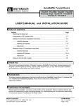
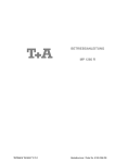
1
R
bfspufdi
R
Ventilation Systems
WF50
50" Fan
WF501TCP,Y,
WF5015TCP, Y
Munters Corporation
4215 Legion Dr. Mason, MI 48854-1036 USA
Ph. (517) 676-7070 Fax (517) 676-7078
www.munters.us/aerotech
FORM: QM1072
Rev. 4, June 2009
Page 1 of 12
USER'S MANUAL and INSTALLATION GUIDE
TABLE OF CONTENTS
Section
Page
Unpacking the Fan(s) ..................................................................................................2
Fan Dimensions...........................................................................................................2
Installation ................................................................................................................. 3-4
Electrical Wiring ......................................................................................................... 5-6
Shutter Installation .......................................................................................................6
Operation .....................................................................................................................7
Maintenance .............................................................................................................. 7-9
Troubleshooting ...........................................................................................................9
Warranty ......................................................................................................................9
Exploded View ......................................................................................................... 10-11
THANK YOU
Thank you for purchasing an Aerotech WF Series fan. Aerotech equipment is designed to be
the highest performing, highest quality equipment you can buy. With the proper installation
and maintenance it will provide many years of service.
PLEASE NOTE
To achieve maximum performance and insure long life from your Aerotech fan it is essential that
it be installed and maintained properly. Please read all instructions carefully before beginning
installation.
WARRANTY
For Warranty claims information see the "Warranty Claims and Return Policy" form QM1021
available from the Aerotech Ventilation System, Munters Corporation office at 1-800-227-2376 or
by e-mail at [email protected].
Conditions and Limitations:
• Products and Systems involved in a warranty claim under the "Warranty Claims and Return
Policy" shall have been properly installed, maintained and operated under competent
supervision, according to the instructions provided by Aerotech Ventilation Systems,
Munters Corporation.
• Malfunction or failure resulting from misuse, abuse, negligence, alteration, accident or lack
of proper installation or maintenance shall not be considered a defect under the Warranty.
Munters Corporation
4215 Legion Dr. Mason, MI 48854-1036 USA
Ph. (517) 676-7070 Fax (517) 676-7078
www.munters.us/aerotech
FORM: QM1072
Rev. 4, June 2009
Page 2 of 12
UNPACKING THE EQUIPMENT
Before beginning installation, check the overall condition of the equipment. Remove packing
materials, and examine all components for signs of shipping damage. Any shipping damage is the
customer's responsibility and should be reported immediately to your freight carrier.
Each Crate Includes:
1 – 50” Belt Drive Fan
4 – Cone Sections
4 – Cone Support Brackets
1 – Cone Guard
1 – Shutter
1 – Hardware Package (HP1110)
[A]
[B]
HP1110 for WF50 Fan
[C]
--Hardware for Cone Installation--
[A]….12 - ¼” x 1¾” Flange Head Bolts, ZP
[B]….16 - ¼” x ½” Flange Head Bolts, ZP
[C]….28 - ¼” Flange Nuts, ZP
[D]…...8 - ¼” x ¾” TEK Screws, ZP
[E]….12 - ¾” O.D. x 1”L. Spacers
--Hardware for Fan Installation-[F]….12 - ¼” x 1.5” Lag Screws, ZP
[D]
[E]
[F]
Fan Specifications: 60Hz shown (50Hz available)
Power: 120/240 VAC or 208-240/480 VAC
Phase:
1
or
3
E
NOTE: Crate may contain Fan Accessories.
Wall Opening
B
D
Wall Opening
G
A
Shutter
A
Wall Opening
F
C
C
CAT. NO.
WF50
FAN
DIA.
50"
A
B
593/8" 461/2"
C
93/4"
D
541/8"
E
571/8"
F
G
215/16" 591/16"
Wall Opening
(I.D., framed)
55"W. x 561/4"H.*
*Opening based on 2 x 4 framing. Opening size may change with framing. See Chart A page 3.
Munters Corporation
4215 Legion Dr. Mason, MI 48854-1036 USA
Ph. (517) 676-7070 Fax (517) 676-7078
www.munters.us/aerotech
FORM: QM1072
Rev. 4, June 2009
Page 3 of 12
INSTALLATION INSTRUCTIONS
Clearance Notes:
Step 1
Construct the framed opening to correct size according to the Chart
A (below) and your fan size. See Figure 1A and Chart A. If fan
and housing is to be framed into a 2 x 4 wall or concrete wall, See
Figure 1A, 1B, 1C and Chart A for details. For greater than 4" wall
thicknesses, See Figure 1D.
Fan with Discharge
Cone: maintain 12"
minimum clearance
on all sides
See Clearance
Notes, upper
right
Wall Opening
(see chart)
Framing
Wall Opening
(see chart)
12"
Ceiling
A - 2 x Wall Opening
A - 2 x 4 Wall Opening
B - Concrete Wall Opening
Figure 1A
2x4
Figure 1B
Figure 1C
2 x 4 FRAMING
CONCRETE FRAMING
31/2"
Catalog
No.
WF50
A
2 x 4 framing
55"W. x 561/4"H.
B
concrete framing
55"W. x 573/4"H.
Framing cut
at 12° to
match fan
housing
Chart A
Figure 1D
GREATER THAN 4"
WALL THICKNESSES
Munters Corporation
4215 Legion Dr. Mason, MI 48854-1036 USA
Ph. (517) 676-7070 Fax (517) 676-7078
www.munters.us/aerotech
FORM: QM1072
Rev. 4, June 2009
Page 4 of 12
Step 2
Slide fan and housing into framed wall opening. See
Figure 2.
Step 3
Confirm that housing inside dimensions match those
shown in Figure 3A. Then secure housing to wall using 12
Fastener [F], through holes in each mounting flange. See
Figure 3B.
Figure 2
NOTE:
This is NOT the
Wall Opening Size
541/2"
541/8"
Figure 3A
¼" x 1.5"
Lag
Screws [F]
Step 4
Proceed to the Installation Instructions for the Discharge
Cone, Form QM1033 for 50" fans.
Continue to Electrical Wiring section.
Munters Corporation
4215 Legion Dr. Mason, MI 48854-1036 USA
Ph. (517) 676-7070 Fax (517) 676-7078
www.munters.us/aerotech
Figure 3B
FORM: QM1072
Rev. 4, June 2009
Page 5 of 12
ELECTRICAL WIRING
!
WARNING
ROTATING FAN BLADES.
Operation of fan without
wire screens or guards
may result in direct
contact with blades and
cause severe personal
injury or death.
All wiring should be installed in accordance with National, State, and Local
electrical codes. Fans used to ventilate livestock buildings or other rooms
where continuous air movement is essential should be connected to individual electrical circuits, with a minimum of two circuits per room. For electrical
connection requirements, refer to diagram on motor nameplate and to information enclosed with the Aerotech environmental control to be used.
Single Phase Fans: motor overload protection should be provided for each
fan. A
Circuit Breaker Switch or slow blow motor type fuses must be used, See
Figure 4A. See Aerotech form QM1400 for proper size.
Three Phase Fans: motor overload protection should be provided for each
fan. A Circuit Breaker Switch or slow blow motor type fuses must be used,
See Figure 4B. The use of a quality frequency drive and the installation of
line reactors is recommended to reduce voltage spikes and harmonic distortion. Will require three pole contactors with overload protection (by others).
NOTE: A safety cut-off switch should be located adjacent to each fan.
NOTE:
Information in
parenthesis
refers to 120
VAC control.
120 or 240 VAC
Power Supply for
Fan
L1 (H)
L1 (H)
T1 (H)
T1 (H)
L2 (N)
L2 (N)
T2 (N)
T2 (N)
G
G
Figure 4A
Single Phase - Motor Overload Protection with Disconnect
(SY2000 or Equivalent)
KEY:
L1 = Line 1
L2 = Line 2
L3 = Line 3
H = Hot
N = Neutral
G = Ground
Motor Starter
Three Phase
Power Supply for
Fan
120 or 240 VAC
Power Out
to Fan
Saftey cut-off
switch
L1
L1
T1
T1
L2
L2
T2
T2
L3
L3
T3
T3
G
Three Phase
Power Out
to Fan Motor
G
Figure 4B
Three Phase - Motor Overload Protection with Disconnect
Munters Corporation
4215 Legion Dr. Mason, MI 48854-1036 USA
Ph. (517) 676-7070 Fax (517) 676-7078
www.munters.us/aerotech
FORM: QM1072
Rev. 4, November 2008
Page 6 of 12
Recommended wire routing (two options):
Step 1
As the power cable exits the back of the motor form a drip loop and then run cable through side of
fan housing, through flexible conduit and into building. See Figure 5A and 5B.
Step 2
As the power cable exits the back of the motor form a drip loop and then run cable up through
housing and frame into wall cavity and into building. See Figure 6A and 6B.
2"
Drip
loop
Drip loop
Figure 5A
Figure 5B
Figure 6A
Figure 6B
Step 3
Add flashing and/or caulk around completed housing on exterior side of building wall.
Step 4
Make electrical connections to fan motor per instructions provided with fan or as shown on motor.
See Electrical Wiring Section on page 5.
SHUTTER INSTALLATION
Step 5
Insert shutter into fan by sliding the bottom flange of shutter into bottom shutter clips and pressing
shutter inward, See Figure 7A. Fasten shutter in place by rotating the side and top shutter clips over
the shutter flanges, See Figure 7B.
Shutter clip
Shutter Clip
Figure 7B
Figure7A
Munters Corporation
4215 Legion Dr. Mason, MI 48854-1036 USA
Ph. (517) 676-7070 Fax (517) 676-7078
www.munters.us/aerotech
FORM: QM1072
Rev. 4, November 2008
Page 7 of 12
OPERATION
!
WARNING
1) INITIAL START-UP: With electrical power off, verify that the fan propeller turns freely and that all fasteners are secure. Turn on electrical power and
confirm that the fan operates smoothly.
2) ADJUSTMENTS: Set the fan control to the temperature shown on your
Aerotech ventilations system drawing, or to a value which will provide the
desired environmental conditions.
Moving parts,
disconnect power
before servicing.
Single Phase Fans: Single phase fans are designed for single speed operation only.
Three Phase Fans:
1) The use of a quality frequency drive and the installation of line reactors is
recommended to reduce voltage spikes and harmonic distortion.
2) Minimum operating frequency of 30 Hz.
3) Will require three pole contactors with overload protection (by others).
MAINTENANCE
!
WARNING
The following inspection and cleaning procedures should be performed monthly:
TOOLS NEEDED FOR MAINTENANCE:
wrenches: 10mm, 13mm, 16mm, 17mm, 27mm, ½", 6mm Hex
High Voltage,
disconnect power
before servicing.
!
WARNING
Moving parts,
disconnect power
before servicing.
1) INSPECT PROPELLER: Check that propeller is secure on drive hub and
that there are no signs of damage. The blades are of a self-cleaning design
and should not require maintenance.
2) CLEAN regularly for best results:
• FAN MOTOR: Remove any dust accumulation from motor using a brush
or cloth. (DO NOT use a pressure washer). A clean motor will run cooler
and last longer. At the same time, verify that the motor is secure in its
mount.
• SHUTTER: Carefully clean dust from shutter blades and frame so that
shutter opens and closes freely. A brush or cloth should be used.
• GUARD: Clean any dust or feathers from fan guards using a brush. Dirty
guards can reduce airflow.
3) CHECK FASTENERS: For safety, all fasteners should be inspected. Tighten
any loose connections.
4) INSPECT FAN CONTROL: With power disconnected, inspect all electrical
connec-tions. Wiring should be secure and in good condition. Remove
any dust build-up from control case and sensor using a soft brush or
cloth. NEVER CLEAN ELECTRICAL EQUIPMENT WITH A PRESSURE
WASHER!
Munters Corporation
4215 Legion Dr. Mason, MI 48854-1036 USA
Ph. (517) 676-7070 Fax (517) 676-7078
www.munters.us/aerotech
FORM: QM1072
Rev. 4, June 2009
Page 8 of 12
!
WARNING
Do not power wash
electrical devices.
!
WARNING
Moving parts,
disconnect power
before servicing.
5) CHECKING PULLEYS: Roll the belt off and
look at both pulleys. If the pulley has grooves
in it or is no longer smooth, it needs replace
ment. A loose or slipping belt will reduce fan
performance up to 60% and cause premature
belt failure.
Smooth
Pulley
Grooved
Pulley
6) CHECK DRIVE ALIGNMENT:
Check alignment of belt on idler
Propeller
pulley, it should be centered on the
Idler Pulley Motor
Pulley
Pulley
Belt
idler pulley. The belt tensioner’s idler
pulley and propeller pulley are fixed in
position, therefore,
Straight Edge
alignment must be obtained by
adjusting the motor and propeller
pulleys. If an adjustment is needed, remove the belt, then loosen the set
screws in the pulley and move as necessary to achieve proper alignment.
Remember to tighten the pulley set screws after making an
adjustment. Drive alignment is very important for long belt life and proper
operation.
7) BELT TIGHTENING:
To adjust the belt tensioner to the proper setting, loosen 10 mm bolt
(using 16mm or 17mm end wrench) to allow tensioner arm to rotate.
Working from inlet/motor side of fan, place a 27 mm (11⁄16”) wrench onto
the hex on the tensioner. Turn wrench clockwise until the single mark
on base of the belt tensioner is aligned with mark 2 on the tensioner
arm. Hold tensioner at this setting and tighten the 10mm bolt to 40 ft.-lbs
torque
10mm
Bolt
Arrow
on
Base
Munters Corporation
4215 Legion Dr. Mason, MI 48854-1036 USA
Ph. (517) 676-7070 Fax (517) 676-7078
www.munters.us/aerotech
Mark 2 on
Tensioner
Arm
FORM: QM1072
Rev. 4, June 2009
Page 9 of 12
WINTERIZING FAN
In most climates, it is probable that the ventilation system will never need to operate at a total capacity during the colder winter months. Consequently, it is advisable to "winterize" those fans which
will not be used in cold weather to avoid unnecessary heat loss and condensation.
To winterize, turn fan control "off" and install an insulated closure panel over the fan intake. If you
don't have an insulated closure panel, a piece of rigid insulation material can be used. Remember
the insulation panel must be removed before warmer weather returns.
NOTE: At least one single speed fan should be left uncovered and with power available to provide
air movement in the event of variable speed control difficulties.
TROUBLE SHOOTING
!
WARNING
High Voltage,
disconnect power
before servicing.
!
WARNING
Moving parts,
disconnect power
before servicing.
WARNING
Moving parts,
disconnect power
before servicing.
POSSIBLE CAUSES
SYMPTOM
Fan Not Operating
!
CORRECTIVE ACTION
1. Fan control set above room
temperature
2. Blown fuse or open circuit breaker
3. Propeller blade contacting fan
housing
4. Fan control defective
5. Motor defective
1. Set to a lower temperature
Fan OperatingInsufficient Airflow
1.
2.
3.
4.
1.
2.
3.
4.
Excessive Fan
Noise
1. Propeller blade contacting fan panel
2. Motor bearing defective
1. Realign propeller in fan housing
2. Repair or replace motor
Excessive Fan
Vibration
1. Motor loose in mount
2. Propeller damaged
3. Motor shaft bent
1. Tighten fasteners
2. Replace propeller
3. Repair or replace motor
Fan Never Turns Off
1. Override thermostat set incorrectly
2. Control set for continuous operation
1. Set to the correct temperature
2. Set speed control correctly
Shutter jammed
Guard dirty
Incorrect Belt Tension
Worn pulleys.
Munters Corporation
4215 Legion Dr. Mason, MI 48854-1036 USA
Ph. (517) 676-7070 Fax (517) 676-7078
www.munters.us/aerotech
2. Replace fuse or reset breaker
3. Realign propeller in fan housing
4. Repair or replace control
5. Repair or replace motor
Clean shutter & fan housing
Clean guard
See Maintenance Section.
See Maintenance Section.
FORM: QM1072
Rev. 4, June 2009
Page 10 of 12
Munters Corporation
4215 Legion Dr. Mason, MI 48854-1036 USA
Ph. (517) 676-7070 Fax (517) 676-7078
www.munters.us/aerotech
WF50 Fan
FORM: QM1072
Rev. 4, November 2008
Page 11 of 12
WF50 Fan
Item
Cat. No.
Part Name/Description
Qty.
1
FH1951
Orifice panel, galvanized
1
2
FH2919
Top housing panel, galvanized, with shutter clips
1
3
FH2920
Left side housing panel, galvanized, with shutter clips
1
4
FH2918
Bottom housing panel, galvanized, with shutter clip
1
5
FH2921
Right side panel of housing, galvanized, with shutter clip
1
6
FP2548
Prop assembly, 3-blade, SS, 25mm
1
FP2549
Prop assembly, 3-blade, galvanized
1
7
FH2429
Support Bracket for motor mounting plate, galvanized
1
8
FH2427
Mounting Plate for NEMA 56 motor
1
9
FH2428
Center support brace for Strut, galvanized
2
10
FM1024*
Motor, 1HP, 1725 RPM, 56Fr., 1ph, 120/240
1
11
FH1302
Reinforced Brackets for Strut, galvanized
2
12
KN1860
Hex nut, M25x10mm, zinc plated
1
13
KX1208
Cover plastic
1
14
FH1930
Strut, galvanized
1
15
FH1932
Spacer plate, plastic
2
16
FH1505*
V-belt, 87" A-section (A85), polyestar
1
17
KX1130
Bushing, aluminum
1
18
FH2137*
Propeller sheave, aluminum
1
19
FP2060
Hub with bearing and shaft
1
20
FH2504
Mounting bracket for belt tensioner
1
21
FH2402
Belt tensioner assembly with 3" idler pulley
1
FH2406
3" idler pulley only, with bolt
1
FH2419
Tensioner arm only, aluminum
1
22
FH2138*
Motor Sheave AK35x5/8" bore with keyseat, CI
1
23
FH2130
Cone support bracket, GC type, galvanized
4
24
FH4250
Discharge cone (1 section), galvanized
4
25
KX1256
Spacer 0.32 ID x 3/4" OD. x 1.0"L, black NY
12
26
FH2648
Guard, pvc coated
1
27
PZ48 or GS48 or SW54
Shutter, 53 7/8", all plastic or aluminum
1
* Parts listed are for standard configuration with 1HP motor and other drive components operating on 60Hz
power. Contact office for other replacement motors.
Munters Corporation
4215 Legion Dr. Mason, MI 48854-1036 USA
Ph. (517) 676-7070 Fax (517) 676-7078
www.munters.us/aerotech
FORM: QM1072
Rev. 4, November 2008
Page 12 of 12