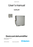
1
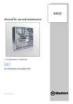
AeroBaffle Tunnel Doors
TDxx96T • TDxx96B • TDxx00T • TDxx00B
Reversed Hinge: TDxx96T-R • TDxx96B-R •
TDxx00T-R • TDxx00B-R
USER'S MANUAL and INSTALLATION GUIDE
TABLE OF CONTENTS
Section
Page
Unpacking the Equipment.........................................................................................................1
Components List & Exploded View......................................................................................... 2-3
Standard Tunnel Doors Installation Instructions...................................................................... 4-5
...........Installing Hardware........................................................................................................6
...........Installing Lift Brackets................................................................................................. 7-10
...........Adjustment.................................................................................................................... 11
Reversed Hinge (-R) Installation Instructions ....................................................................... 12-13
...........Installing Hardware.......................................................................................................14
...........Installing Lift Brackets................................................................................................ 15-18
...........Adjustment....................................................................................................................19
Optional Latch Kit (both models)..............................................................................................20
Thank You
Thank you for purchasing Aerotech, A Munters Company, AeroBaffle Tunnel Doors. Aerotech equipment is
designed to be the highest performing, highest quality equipment you can buy. With the proper installation
and maintenance it will provide many years of service.
PLEASE NOTE
To achieve maximum performance and insure long life from your AeroBaffle Tunnel Doors it is essential that
it be installed and maintained properly. Please read all instructions carefully before
beginning installation.
unpacking the equipment
Before beginning installation, check the overall condition of the equipment. Remove packing materials, and
examine all components for signs of shipping damage. Any shipping damage is the customer's responsibility
and should be reported immediately to the freight carrier.
Munters Corporation
4215 Legion Dr. Mason, MI 48854-1036 USA
(517) 676-7070 Fax (517) 676-7078
FORM QM1043
Rev. 4, July 2007
Page of 20
UNPACKING THE EQUIPMENT
Tunnel Door Series Components
The shipment contains 96" midsection doors, along with boxed hardware. Also, the completer kits contains 48",
right and left doors along with boxed hardware. Optional installation kits and latch kits will be in the hardware
boxes. Optional cable will be on a spool.
Component descriptions:
• Midsection doors are 96" long doors with a hinge, a top seal, an I-beam, and a bare side.
• Right doors are 48" long doors with a hinge, a top seal, a right seal, and bare side.
• Left doors are 48" long doors with a hinge, a top seal, a left seal, and a I-beam.
• Top door lift bracket hardware consists of a lift/brace bracket, two each of bolts (1/4" x2), washers, and nuts.
Two lift brackets per 96" door and 1 bracket per 48" door. For doors 36" high and 96" long use 3 lift brackets.
• Bottom door lift bracket hardware is the same as the top door with the addition of a bottom lift bracket, 2 bolts
(1/4" X 5/8") and nuts.
• Optional Installation Kit (FA1502) provides 2 each of lift lines, screw hooks, pulleys, 3/16" cable clamps and 4
Azuma nuts.
• Optional Latch Kit (FA1560) provides 2 each of locking arms, 1" spacers, 3/4" spacers and 31/2" lag screws.
• Customer supplied materials consists of sealant, weather stripping, and mounting screws. Recommendations
for customer supplied materials. Weather resistant sealant, weather stripping at least 1/2"W x 5/8"H mounting
screws, #8 x 3/4" Kwikseal Woodbinder screws, common for attaching sheet metal to wood structures.
See Exploded view for more details.
Munters Corporation
4215 Legion Dr. Mason, MI 48854-1036 USA
(517) 676-7070 Fax (517) 676-7078
FORM QM1043
Rev. 4, July 2007
Page of 20
Tunnel Doors
Top Seal
Right
Seal
Hinge
Top Seal
I-Beam
r
oo
ht D
Rig 48"
Hinge
Top Seal
oor
D
ion
ect "
s
96
Mid
I-Beam
Left
Seal
Hinge
or
t Do
Lef 8"
4
No.
Part Name/Description
1
2
3
4
5
6
7
8
9
10
11
12
13
14
15
16
17
18
Left door
Mid-section Door
Right Door
3/16" Cable Clamp
Pulley, Swivel, 7/8"
Screw Hook
Lift Line (coated cable)
Azuma Nut & Bolt
Bottom Lift Bracket
Lift Brace Bracket
Elevator Bolt
1/4" - 20 x 5/8" Bolt
#10 x 1/2" TEK screw
1/4" - 20 Keps Nut
31/2" Lag Screw
Locking Arm
1" Spacer
3/4" Spacer
Cat. No.
all
---AC1039
AC1239
KS2601
AC1245
AC1210
AC2122
-KS1205
KS1027
KS2301
KN1558
KS2465
AC2412
KX1256
KX1257
Munters Corporation
4215 Legion Dr. Mason, MI 48854-1036 USA
(517) 676-7070 Fax (517) 676-7078
Cat. No.
16"
AC3172
AC3148
AC3162
Cat. No.
24"
AC3170
AC3150
AC3160
Cat. No.
28"
AC3173
AC3149
AC3163
Cat. No.
30"
AC3174
AC3151
AC3164
Cat. No.
36"
AC3175
AC3155
AC3165
AC2416
AC2424
AC2428
AC2430
AC2436
FORM QM1043
Rev. 4, July 2007
Page of 20
INSTALLATION INSTRUCTIONS
Frame Wall Opening Dimensions (I.D.)
• Height is equal to tunnel door height less 7/8", with a tolerance of ± 1/8"
example: a) 24" door height = 231/8" opening
b) 30" door height = 291/8" opening
• Length is equal to tunnel door length less 2"
example: a) 32' long door = 31'10" opening
b) 56' long door = 55'10" opening
Note: It is required that the tunnel door frame is taller and longer than the wall opening. The tunnel door frame
height and length, outside dimensions, should be slightly bigger than the tunnel door height and length, as
noted above, to assure proper seal. For Standard Tunnel Door models, See Figures 1A-1E for more details.
IMPORTANT – Seal tunnel door frame with caulk or sealant. Failure to seal gaps will result in air
leakage.
If using a Tunnel Door models with '-R' or Reversed Hinged, proceed to page 12.
2x4
Frame
End
2x4
Wall Stud or Post
Figure 1D
Framed
Opening Height
2"
Framed
Opening Height
2"
2"
Critical
Door Height
Less 7/8"
Critical
Door Height
Less 7/8"
2x6
Figure 1C
Frame
Middle
Frame
Bottom
2"
2x2
2x4
Frame
End
Frame Top
2x2
2x4
Frame
End
2x6
"
s2
Les
in
pen
eo
m
Fra
h
l
ngt
tica
Cri oor Le
D
g=
Figure 1A
Figure 1B
Munters Corporation
4215 Legion Dr. Mason, MI 48854-1036 USA
(517) 676-7070 Fax (517) 676-7078
FORM QM1043
Rev. 4, July 2007
Page of 20
Standard Tunnel Door
1) Begin the frame by fastening 2x4 (frame bottom) material to wall studs. Start the 2x4 even with the wall
opening. Continue until the FRAME OPENING LENGTH is achieved. The tunnel door frame should completely
enclose the wall opening. See Figures 1A & 1B.
2) Using a level to set the 2x2, fasten it along the 2x4 (frame bottom) material. It is important the 2x2 be level as
this is where the door mounts. The 2x2 should overhang the ends of the 2x4 (frame bottom) by 2". See Figure
1B.
3) Using the proper FRAME OPENING HEIGHT DIMENSION from below, measure from top surface of the level
2x2 and mark the wall studs accordingly. Fasten 2x6 (frame middle) material to wall studs. Bottom of 2x6
should be even with the markings on the wall studs. Start the 2x6 even with the wall opening. See Figure 1C.
4 ) Using a level to set the 2x2, fasten it along the 2x6 (frame middle) material, as close to the top as possible,
keeping the 2x2 level. The 2x2 should overhang the ends of the 2x6 by 2".
5) Using the proper FRAME OPENING HEIGHT DIMENSION from below, measure from top surface of the level
2x2 and mark the wall studs/wall accordingly. Fasten 2x4 (frame top) material to wall studs/wall. Start the
2x 4 even with the wall opening. Bottom of the 2x4 should be even with the markings on the wall studs/wall.
See Figure 1D.
6) Close in the frame by adding 2x4 (frame end) pieces to both ends of the frame.
IMPORTANT – Seal tunnel door frame with caulk or sealant. Failure to seal gaps will result in air leakage.
FRAME MIDDLE:
2x6 required for double cable system
2x4 required for single cable system
Critical Door
Height Less
7/8"
Critical Door
Height Less
7/8"
Munters Corporation
4215 Legion Dr. Mason, MI 48854-1036 USA
(517) 676-7070 Fax (517) 676-7078
FORM QM1043
Rev. 4, July 2007
Page of 20
INSTALLIng Hardware
8) Attach the main cable to the actuator and pull it from actuator end of the tunnel door frame to opposite end
of frame, it may be necessary to install some screw hooks, temporarily, to hold the cable in place along the
frame top. See Figure 2A & 2C.
9) Actuator should be in the ‘open door’ position. Install screw hooks along the frame and 1½" off center of the
lift brackets on the top doors, as the doors are installed. The 1½" offset should be tword the actuator
machine. If two main cables are used place the screw hooks above the bottom doors also. Attach pulleys to
screw hooks, route lift lines to the main cable and attach with cable clamps, see Figure 2B.
After doors are completely installed the cable clamps will need to be repositioned to act as safety stops.
24"
Main Cable (required)
48"
Frame Top
Main Cable
(required for
double cable
system)
Frame Middle
Support
Frame Top
2½"
Frame Bottom
Figure 2A
1"
Required for Double Cable System
2x2
2x2
Screw Hook
Main Cable
/ " Cable Clamp
2 x 6 Frame
Middle Support
3 16
2½"
2x6
Lift Line to Lift
Bracket
Pulley
Figure 2B
Munters Corporation
4215 Legion Dr. Mason, MI 48854-1036 USA
(517) 676-7070 Fax (517) 676-7078
Figure 2C
1"
FORM QM1043
Rev. 4, July 2007
Page of 20
INSTALLIng lift brackets
10) Install lifting brackets on the doors before hanging the doors, the bolt head and washer should be on the
opposite side of the door than the lift bracket and nut, See Figure 3A. Use a 9/32" (0.281") drill bit to make
two holes. Use the lift brace bracket for a drill template, See Figure 3B. The holes should penetrate the top
seal and the bottom hinge. The brackets should be positioned 24" from the ends of the doors, See Figure
3A.
NOTE: Tunnel doors 36" high and 96" long require 3 lift brackets, all others 96" long require 2 lift
brackets.
/ " x 2" Bolt
1 4
Bottom Door
Lift Bracket
¼" - 20 Keps Nut
¼" - 20 x 5/8" Bolt
Lift Door Brace
Bracket
Use 9/32" drill bit making 2 holes
Center lift brace
bracket for use on
36" tunnel doors only
Figure 3A
Use Lift Line
Bracket for Drill
Template
Drill for optional
Locking Bracket
Figure 3B
Munters Corporation
4215 Legion Dr. Mason, MI 48854-1036 USA
(517) 676-7070 Fax (517) 676-7078
FORM QM1043
Rev. 4, July 2007
Page of 20
11)Always start with a right or left end door (48" long door from a completer kit). The end door seal should
overlap the frame end 2x4 by 1.0" to provide a good seal See Figure 4C. Apply a bead of sealant to the 2x2,
See Figure 4A, 4B. This will prevent leaks between the 2x2 and the hinge.
12)Place the door on the 2x2 in the closed position, overlapping the frame end by 1.0", and fasten in place
with screws every 3.½", not too tight, along indented line in rigid hinge piece. Attach lift line to lift bracket,
using the Azuma nut, to hold the door in the open position. Use the same procedure for top and bottom end
doors. See Figures 4A, 4B, 4C.
Frame
Top
Right Door
Frame
Middle
Support
Main
Cable
Hinge Door
Right Door
Steel siding
screws
Bead of
Sealant
Frame
Middle
Support
Frame Top
/16" cable
clamp
3
Screw hook
Lift Line to
Lift Bracket
Pulley
3½"
/"
3 4
Front Door
Figure 4A
Required for Single Cable System
Munters Corporation
4215 Legion Dr. Mason, MI 48854-1036 USA
(517) 676-7070 Fax (517) 676-7078
Azuma nut & bolt
Lift door brace
bracket
FORM QM1043
Rev. 4, July 2007
Page of 20
Screw hook
2x4
Door
Lift
Bracket
Brace
2x6
Bead of
Sealant
Hinge Door
Lift Bracket
Screw hook
2x6
Figure 4B
Required for Double Cable System
13)Mid-section doors, apply a bead of sealant to the 2x2 as shown Figure 4B, 4C this will prevent leaks between
the 2x2 and the hinge. Allow for thermal expansion when installing the doors in a temperature less than 40oF.
Leaving a 1/8" to 1/4" gap between the doors will allow for the necessary expansion.
1"
2x4
Figure 4C
Munters Corporation
4215 Legion Dr. Mason, MI 48854-1036 USA
(517) 676-7070 Fax (517) 676-7078
FORM QM1043
Rev. 4, July 2007
Page of 20
14)With the installed door(s) in the open position, slide doors together from the top, as shown in Figure 5. The
I-Beam can be spread apart to fit around the other door. IMPORTANT - It is necessary to position doors in
the open position while sliding them together,
and in the closed position for attachment to
the frame. Placing the doors in the open
position allows for viewing on both sides
of the door to verify I-Beam enclosed mating
I-beam
door. Close the doors and fasten in place with
screws every 3½" not too tight, along indented
line in rigid hinge piece. Important - Placing
Middle section
door
the door in its closed position for attachment
it to the frame will ensure proper seating on
the level 2x2 and with the other doors.
Attach lift line to lift bracket, using the Azuma
nut, to hold the door in the open position.
15)IMPORTANT – Reopen doors and install Tek (self
tapping) screws, two on front and two on back,
where the I-Beam overlaps the bare edge of the
mating door. The Tek screw should go through the
I-Beam and corrugated plastic cover sheet. The
screws will mechanically fasten the two doors
together. See Figure 6.
Figure 5
16)Continue installing midsection doors, using same
method outlined above. Attach lift lines to lift
brackets as you proceed, using the Azuma nuts to
hold the doors in the open position. At about four
feet from the end of the frame opening, add the
other end door (48" long door from a Completer
Kit).
17)The end door seal, should overlap the frame end
2x4 by 1.0", apply a bead of sealant to the 2x2 See Figure 4., slide doors together and fasten in place. This end door completes the run.
Top Seal
Top Seal
4 TEK screws
Hinge
I-Beam
Lift
Seal
I-Beam
Top Seal
or
t do
Lef 8"
4
d
ion
ect "
s
d
96
Mi
Hinge
n
ctio
-se 6"
9
Mid
Munters Corporation
4215 Legion Dr. Mason, MI 48854-1036 USA
(517) 676-7070 Fax (517) 676-7078
oor
I-Beam
Hinge
r
doo
Figure 6
FORM QM1043
Rev. 4, July 2007
Page 10 of 20
adjustment
IMPORTANT – this process must be completed to ensure proper seal of the doors to the frame, otherwise there will be unnecessary air leakage.
18)Safety Stop Adjustment: With the doors in the open position, move all the lift line cable clamps (3/16" clamps)
until they touch the screw hooks and pulleys. This will prevent damage to the door if the main cable
happens to break.
19)Door Adjustment: Move the doors toward the closed position until the first door makes contact with the
frame. Adjust the other doors to closed position using the Azuma nut and lift lines.
20)The actuator closed limit switch should be set at this position.
21)Seal Adjustment: With the doors in the closed position, mark the frame where the seal makes contact. Open
the doors and apply weather stripping (9/16"H x 3/4"W) along the mark on the frame. The weather stripping
should be on the wall opening side of the mark. This will ensure a tight seal to prevent air leakage. See
Figure 7.
22)
Screw Hook
Screw Hook
Weather
Strip
2x4
Weather Strip
2x6
Bottom
Door
Bottom
Door
Top
Door
Lift Brace
Bracket
Top Door
Weather Strip
2x4
Lift Brace
Bracket
Bottom Door
Double Cable System
Bottom Lift
Bracket
Lift Brace
Bracket
Bottom Door
Single Cable System
Figure 7
Munters Corporation
4215 Legion Dr. Mason, MI 48854-1036 USA
(517) 676-7070 Fax (517) 676-7078
FORM QM1043
Rev. 4, July 2007
Page 11 of 20
INSTALLATION INSTRUCTIONS - Reversed hinge (-R)
Note: It is required that the tunnel door frame is taller and longer than the wall opening. The tunnel door
frame height and length, outside dimensions, should be slightly bigger than the tunnel door height and length,
as noted below, to assure proper seal. See Figures 8A-8E for more details.
1) Using a level, begin the frame by fastening 2x4 (frame bottom) material to wall studs. Start the 2x4 even
with the wall opening. It is important the 2x4 be level as this is where the door mounts. Continue until
the FRAME OPENING LENGTH is achieved. The tunnel door frame should completely enclose the wall
opening. See Figure 8B.
2) Using the proper FRAME OPENING HEIGHT DIMENSION from below, measure from top surface of the
level 2x4 and mark the wall studs accordingly. Fasten 2x4 (frame middle) material to wall studs. Bottom
of 2x4 should be even with the markings on the wall studs. Start the 2x4 even with the wall opening. See
Figure 8C.
3) Using the proper FRAME OPENING HEIGHT DIMENSION from below, measure from top surface of the
level 2x4 and mark the wall studs/wall accordingly. Fasten 2x4 (frame top) material to wall studs/wall. Start
the 2x4 even with the wall opening. Bottom of the 2x4 should be even with the markings on the wall studs/
wall. See Figure 8D.
4) Close in the frame by adding 2x4 (frame end) pieces to both ends of the frame.
IMPORTANT – Seal tunnel door frame with caulk or sealant. Failure to seal gaps will result in air
leakage.
Wall Stud or Post
2x4
Frame
End
2x4
Framed
Opening Height
Figure 8D
Frame Top
2x4
Critical
Door Height
Less 7/8"
2x4
Frame
End
Framed
Opening Height
Critical
Door Height
Less 7/8"
Frame
Middle
Figure 8C
ess
Frame Bottom
2x4
2x4
Frame
End
me
Fra
hL
l
ngt
tica
Cri oor Le
=D
ing
2"
n
ope
Figure 8A
Figure 8B
Munters Corporation
4215 Legion Dr. Mason, MI 48854-1036 USA
(517) 676-7070 Fax (517) 676-7078
FORM QM1043
Rev. 4, July 2007
Page 12 of 20
Frame Wall Opening Dimensions (I.D.)
• Height is equal to tunnel door height less 7/8", with a tolerance of ± 1/8"
example: a) 24" door height = 231/8" opening
b) 30" door height = 291/8" opening
• Length is equal to tunnel door length less 2"
example: a) 32' long door = 31'10" opening
b) 56' long door = 55'10" opening
FRAME MIDDLE:
2x4 required for double cable system
2x4 required for single cable system
Critical Door
Height Less
7/8"
Critical Door
Height Less
7/8"
Figure 8E
Munters Corporation
4215 Legion Dr. Mason, MI 48854-1036 USA
(517) 676-7070 Fax (517) 676-7078
FORM QM1043
Rev. 4, July 2007
Page 13 of 20
INSTALLIng Hardware, -R
5) Attach the main cable to the actuator and pull it from actuator end of the tunnel door frame to opposite end
of frame, it may be necessary to install some screw hooks, temporarily, to hold the cable in place along the
frame top. See Figure 9A & 9C.
6) Actuator should be in the ‘open door’ position. Install screw hooks along the frame and 1½" off center of the
lift brackets on the top doors, as the doors are installed. The 1½" offset should be twords the actuator
machine. If two main cables are used place the screw hooks above the bottom doors also. Attach pulleys to
screw hooks, route lift lines to the main cable and attach with cable clamps, See Figure 9B .
After doors are completely installed the cable clamps will need to be repositioned to act as safety stops.
24"
Main Cable (required)
48"
Main Cable
(required for
double cable
system)
Frame Top
Frame Top
Frame Middle
Support
2½"
1"
Required for Double Cable System
Frame Bottom
Figure 9A
2 x 4 Frame
Middle Support
2x2
Screw Hook
2½"
Main Cable
/ " Cable Clamp
3 16
Figure 9B
1"
2x4
Pulley
Lift Line to Lift
Bracket
Munters Corporation
4215 Legion Dr. Mason, MI 48854-1036 USA
(517) 676-7070 Fax (517) 676-7078
Figure 9C
FORM QM1043
Rev. 4, July 2007
Page 14 of 20
INSTALLIng lift brackets, -R
7) Install lifting brackets on the doors before hanging the doors, the bolt head and washer should be on the
opposite side of the door than the lift bracket and nut, See Figure 10A. Use a 9/32" (0.281") drill bit to make two
holes. Use the lift brace bracket for a drill template, See Figure 10B. The holes should penetrate the top seal
and the bottom hinge. The brackets should be positioned 24" from the ends of the doors, See Figure 10A.
NOTE: Tunnel doors 36" high and 96" long require 3 lift brackets, all others 96" long require 2 lift
brackets.
Bottom Door Lift Bracket
/ " x 2" Bolt
1 4
/ " Keps Nut
1 4
1
/4" x 5/8" Bolt
Lift Door Brace
Bracket
Use 9/32" drill bit making 2 holes
Center lift brace bracket
for use on 36" tunnel
doors only
Figure 10A
Use Lift Line
Bracket for Drill
Template
Drill for optional
Locking Bracket
Figure 10B
Munters Corporation
4215 Legion Dr. Mason, MI 48854-1036 USA
(517) 676-7070 Fax (517) 676-7078
FORM QM1043
Rev. 4, July 2007
Page 15 of 20
8) Always start with a right or left end door (48" long door from a completer kit). The end door seal should overlap
the frame end 2x4 by 1.0" to provide a good seal See Figure 11C. To get the proper overlap, trim 1" off of the
rigid hinge on the end of the door you started with. Apply a bead of sealant under the hinge, See Figure 11A,
11B. This will prevent leaks between the 2x4 and the hinge.
9)
Place the door on the 2x4 in the closed position, overlapping the
frame end by 1.0", and fasten in place with screws every 3½",
not too tight, along indented line in rigid hinge piece. Attach
lift line to lift bracket, using the Azuma nut, to hold the door
in the open position. Use the same
procedure for top and bottom end
doors. See Figures 11A-11C.
Frame
Top
Right Door
Frame
Middle
Support
Tunnel
Door
Right
Door
Steel siding
screws
Main
Cable
Hinge Door
Bead of
Caulk
Frame Middle
Support
3
/4"
Frame Top
/ " cable clamp
3 16
Screw hook
Lift Line to
Lift Bracket
3.5"
Figure 11A
Required for Single Cable System
Pulley
Front Door
Azuma nut & bolt
Lift door brace
bracket
Munters Corporation
4215 Legion Dr. Mason, MI 48854-1036 USA
(517) 676-7070 Fax (517) 676-7078
FORM QM1043
Rev. 4, July 2007
Page 16 of 20
Screw hook
2x4
Door
Lift Bracket Brace
Hinge Door
2x6
Screw hook
Lift Bracket
2x6
Figure 11B
Required for Double Cable System
10)Mid-section doors, apply a bead of sealant under hinge as shown Figure 11A this will prevent leaks between
the 2x6 and the hinge. Allow for thermal expansion when installing the doors in a temperature less than 40oF.
Leaving a 1/8" to 1/4" gap between the doors will allow for the necessary expansion.
1"
2x4
Figure 11C
Munters Corporation
4215 Legion Dr. Mason, MI 48854-1036 USA
(517) 676-7070 Fax (517) 676-7078
FORM QM1043
Rev. 4, July 2007
Page 17 of 20
11)With the installed door(s) in the open position, slide doors together from the top, as shown in Figure 12. The
I-Beam can be spread apart to fit around the other door. IMPORTANT - It is necessary to position doors in
the open position while sliding them together,
and in the closed position for attachment to
the frame. Placing the doors in the open
position allows for viewing on both sides
of the door to verify I-Beam enclosed mating
door. Close the doors and fasten in place with
screws every 3½" not too tight, along indented
line in rigid hinge piece. Important - Placing
the door in its closed position for attachment
it to the frame will ensure proper seating on
the level 2x4 and with the other doors.
I-beam
Attach lift line to lift bracket, using the Azuma
nut, to hold the door in the open position.
Middle section
door
12)IMPORTANT – Reopen doors and install Tek (self
tapping) screws, two on front and two on back,
where the I-Beam overlaps the bare edge of the
mating door. The Tek screw should go through the
I-Beam and corrugated plastic cover sheet. The
screws will mechanically fasten the two doors
together. See Figure 13.
13)Continue installing midsection doors, using same
method outlined above. Attach lift lines to lift
brackets as you proceed, using the Azuma nuts to
hold the doors in the open position. At about four
feet from the end of the frame opening, add the
other end door (48" long door from a Completer
Kit).
Figure 12
14)The end door seal, should overlap the frame end
2x4 by 1.0", trim 1" off the rigid hinged, apply a
bead of sealant to the 2x4, See Figure 11, slide
doors together and fasten in place. This end door
completes the run.
Top Seal
Top Seal
4 TEK screws
Hinge
I-Beam
Left
Seal
I-Beam
Hinge
or
t do
Lef 8"
4
Trim 1"
off rigid hinge
I-Beam
Top Seal
oor
d
ion
ect "
s
96
Mid
Hinge
oor
nd
ctio
-se 6"
d
i
9
M
Figure 13
Munters Corporation
4215 Legion Dr. Mason, MI 48854-1036 USA
(517) 676-7070 Fax (517) 676-7078
FORM QM1043
Rev. 4, July 2007
Page 18 of 20
adjustment
IMPORTANT – this process must be completed to ensure proper seal of the doors to the frame, otherwise there will be unnecessary air leakage.
15)Safety Stop Adjustment: With the doors in the open position, move all the lift line cable clamps (3/16" clamps)
until they touch the screw hooks and pulleys. This will prevent damage to the door if the main cable
happens to break.
16)Door Adjustment: Move the doors toward the closed position until the first door makes contact with the
frame. Adjust the other doors to closed position using the Azuma nut and lift lines.
17)The actuator closed limit switch should be set at this position.
18)Seal Adjustment: With the doors in the closed position, mark the frame where the seal makes contact. Open
the doors and apply weather stripping (9/16"H x 3/4"W) along the mark on the frame. The weather stripping
should be on the wall opening side of the mark. This will ensure a tight seal to prevent air leakage. See
Figure 14.
19)Run the doors open to satisfy the static pressure with all fans on. The actuator open limit switch should be set at this position.
Screw
Hook
Weather Strip
Screw Hook
2x6
Weather Strip
2x4
Weather
Strip
2x4
Bottom
Door
Bottom
Door
Top
Door
Top Door
Lift Brace
Bracket
Lift Brace
Bracket
Bottom Door
Double Cable System
Bottom Lift
Bracket
Lift Brace
Bracket
Bottom Door
Single Cable System
Figure 14
Munters Corporation
4215 Legion Dr. Mason, MI 48854-1036 USA
(517) 676-7070 Fax (517) 676-7078
FORM QM1043
Rev. 4, July 2007
Page 19 of 20
optional latch kit, both models
1) Install optional latch kit as necessary. Locking arms should be positioned close to lift brackets. See Figure 15.
1" Spacer
/ " Spacer
3 4
Locking Arm
31/2" Lag Screw
Figure 15
Munters Corporation
4215 Legion Dr. Mason, MI 48854-1036 USA
(517) 676-7070 Fax (517) 676-7078
FORM QM1043
Rev. 4, July 2007
Page 20 of 20