1
Wiring the bridge pickup to the Chromacaster Switch:
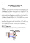
Unsolder the bridge pup leads from where they are currently in your guitar and solder them to
the center lugs on the Chromacaster Switch. Be sure you get the "+" (positive, hot) side - usually
white, it is the lead soldered to the five-way pickup selector - on lug “1,” the lug with the string
through it, and the "-" (negative, ground), usually soldered to the back of the volume pot, on lug
"2" (see drawing). Now your bridge pup goes through the Chromacaster Switch.
NOTE: Sometimes there is not enough wire on the leads to make it to the Chromie, so just add
on a little "tail" to the lead to get there. Be sure you insulate the solder joint on this "tail" to
prevent contact with the pots or any other grounded surface in the control cavity - black electrical
tape or heat shrink tubing will do the trick.
What about THREE-wire pickups?
Some guitars and many after-market pickups are wired with THREE conductors:
The coil's "+" lead, the coil's "-" lead, and the shield/ground lead.
In these cases, remember that the shield/ground STAYS on the guitar's ground, and you will be
lifting the coil's "-" lead - which is often "twisted" with the shield/ground lead - to move it over to
the rotary switch. How to tell which is the coil's "-" and which is the ground lead? IF you don't
have any "paperwork" color-code indicating which is which, a simple test is to use your
multimeter. With the two leads/conductors unsoldered from ground (typically the back of the
volume pot) and separated, set your multimeter in the 20k ohm range. With one probe on the
lead that you know is the coil's "+" lead (it's the one on the pup selector switch), one of the other
two leads will show you a 5k -10k reading when touched with the other probe. That's the
resistance number for your pup, and that's the coil's "-" lead. It is the lead you will move over to
the rotary switch - the other one is soldered back to ground. The same idea works if you have a
four-conductor pickup in your bridge spot, like a Hot Rails or single-coil sized humbucker – the
hot and negative leads go to the Chromie, the “series-pair” stay soldered together, and the bare
wire stays soldered to ground on the back of the volume pot.
The Chromacaster’s pre-wired leads
The WHITE lead from the Chromacaster Switch goes to the bridge pup’s spot on the 5-way where you just removed its "positive" (hot) lead.
The RED lead is soldered to the 5-way switch. It goes on the bridge lug (the third lug) on the
“tone” side of the 5-way, the side that was used to connect the tone pots (see drawing). Run a
jumper from this lug to the first lug of the “tone” side of the selector switch (the lug where the
neck's tone pot was connected).
The BLACK lead is added to the neck pup's lug on the 5-way. It's the wire that will route the
"negative" lead of the bridge pup back through the neck pup for "series" settings.
The GREEN lead is added to the middle pup's lug on the 5-way. It's the wire that will route the
"negative" lead of the bridge pup back through the middle pup for "series" settings.
The BARE wire is soldered to (any) ground.
NOTE: Do not remove the jumper that goes between the common lugs of your 5-way.Put your
pickguard back on, and you're ready to rip!