1
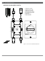
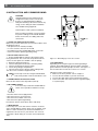
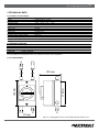
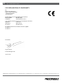
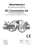
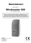
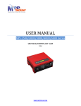
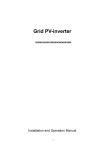
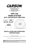
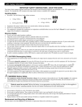
Soladin Web DC Switch
UK | USERS AND INSTALLATION MANUAL | P01
NL | GEBRUIKERS- EN INSTALLATIEHANDLEIDING | P9
DE | BEDIENUNGS- UND INSTALLATIONSANLEITUNG | P17
FR | MANUEL UTILISATEURS ET D’INSTALLATION | P25
ES | MANUAL DEL USUARIO Y DE INSTALACIÓN | P33
IT | MANUALE DI USO E MANUTENZIONE | P41
10000006477/01
2|
EN / Soladin Web DC Switch
OVERVIEW Soladin Web DC Switch
1. Output plus to Soladin
2. Input plus from PV string
3. Output minus to Soladin
4. Input minus from PV string
G. PE terminal positive input(2x)
N. PE terminal minus input (2x)
S. Switch knob
0. Switch Off position
I. Switch On position
1
G
ON
3
0
I ON
N
N
G
2
O
F
F
S
4
Figure 0-1: Overview of the Soladin Web DC Switch
EN / Soladin Web DC Switch
CONTENT
1 GENERAL INFORMATION
1.1 PRODUCT DESCRIPTION
1.2 USE OF THIS MANUAL
1.3 VALIDITY OF THIS MANUAL
1.5 LIABILITY
1.6 CHANGES TO THE Soladin Web DC Switch
1.7 IDENTIFICATION LABEL
1.8 TRANSPORT, LIFTING AND STORAGE
1.9 INSTALLATION ENVIRONMENT
1.10 DC CONFIGURATION
2 SAFETY GUIDELINES AND WARNINGS
2.2 USE FOR INTENDED PURPOSE
2.4 INSTALLATION, MAINTENANCE AND REPAIR
2.5 WARNING OF SPECIAL DANGERS
3 INSTALLATION AND COMMISSIONING
3.1 THINGS YOU NEED FOR INSTALLATION
3.2 INSTALLATION STEP BY STEP
3.3 COMMISSIONING AFTER INSTALLATION
3.4 DE-COMMISSIONING
3.5 MAINTENANCE
3.6 PV grounding
4 TECHNICAL DATA
4.1 TECHNICAL SPECIFICATIONS
5 EC DECLARATION OF CONFORMITY
|3
10000006477/00 July 2013
4
4
4
4
4
4
4
4
4
4
5
5
5
5
6
6
6
6
6
6
6
7
7
8
4|
EN / Soladin Web DC Switch
1 GENERAL INFORMATION
1.1 PRODUCT DESCRIPTION
1.6 CHANGES TO THE Soladin Web DC Switch
The Soladin Web DC Switch disconnects both the positive
and negative cable going from the PV string to the Soladin
Web. It is suitable for the Soladin 700 Web, 1000 Web and
1500 Web.
Changes to the Soladin Web DC Switch may be carried out
only after the written permission of Mastervolt.
1.2 USE OF THIS MANUAL
Copyright © 2013 Mastervolt. All rights reserved.
Reproduction, transfer, distribution or storage of part or all
of the contents in this document in any form without the
prior written permission of Mastervolt is prohibited.
This manual serves as a guideline for the safe and effective
installation of the Soladin Web DC Switch:
• For the electrician this manual provides directions for the
installation, operation and commissioning.
• For the end-user it instructs in operation and maintenance.
• Every person who works with the apparatus should be
familiar with the contents of this manual, and must carefully
follow the instructions contained herein.
• Store the manual in a user accessible place.
1.3 VALIDITY OF THIS MANUAL
All the specifications, provisions and instructions contained
in this manual apply solely to the Mastervolt-delivered
standard version of the Soladin Web DC Switch.
1.4 GUARANTEE SPECIFICATIONS
Mastervolt assures the product guarantee of this DC Switch
during five years after your purchase, on the condition that
all instructions and warnings given in this manual are taken
into account during installation and operation. Installation
must be carried out by a qualified electrician.The warranty
is limited to the costs of repair and/or replacement of the
product by Mastervolt only. Costs for installation labour,
shipping of the defective parts and loss of energy revenues
are not covered by this warranty. For making an appeal on
warranty you can contact your supplier directly, stating your
complaint, application, date of purchase and part number /
serial number.
1.5 LIABILITY
Mastervolt accepts no liability for:
• consequential damage of using the Soladin Web DC
Switch;
• possible errors in the manuals and their results.
1.7 IDENTIFICATION LABEL
The identification label is positioned at the right side of the
Soladin Web DC Switch.
CAUTION!
Never remove the identification label.
1.8 TRANSPORT, LIFTING AND STORAGE
Ensure adequate and secure packaging during transportation of the DC Switch. Always use suitable handling equipment for transportation.
1.9 INSTALLATION ENVIRONMENT
Obey the following stipulations during installation:
• The Soladin Web DC Switch is designed for both indoor
and outdoor use, according to protection class IP66;
• Ambient temperature: -20 to 40°C;
1.10 DC CONFIGURATION
The solar or DC side of the system consists of several photovoltaic (solar) modules, connected as “PV string”. These
strings consist of a plus (+) and a minus (–) connection
which can be connected to the Soladin inverter via the Soladin Web DC Switch. The cabling between the DC Switch
and the inverter must be double insulated and suitable for
400 V DC and 15A DC.
1.11 PV installation requirements
The PV installation has to meet next specifications:
• The maximum open circuit string voltage at lowest
possible temperature of the string may not exceed 400V;
• Double isolated PV wiring, fitted with Amphenol Helios H4
connectors (at the inverter side) must be used;
• The maximum power connected to the switch may not exceed 400Vdc/ 15Adc for each output.
Do not install the Soladin DC Switch if the solar system does
not comply with the stipulations mentioned above.
EN / Soladin Web DC Switch
|5
2 SAFETY GUIDELINES AND WARNINGS
2.1 WARNINGS AND SYMBOLS
Safety instructions and warnings are marked in this manual
by the following pictograms:
A procedure, circumstance, etc which deserves extra attention.
CAUTION!
Special information, commands and
prohibitions in order to prevent damage.
WARNING
A WARNING refers to possible injury to the user or installer or significant material damage to the Soladin Web DC Switch if the installer / user does not (carefully) follow the stated procedures.
2.2 USE FOR INTENDED PURPOSE
Use the Soladin Web DC Switch only in installations that
meet these qualifications:
• in permanent installations;
• the electrical installation must meet the applicable regulations and standards, must be carried out correctly and must
be in a good condition;
• according to the technical specifications.
WARNING
Never use the Soladin Web DC Switch in situations where there is danger of gas or dust
explosion or potentially flammable products!
Use of the Soladin Web DC Switch other than
as mentioned under § 2.2 is not considered to
be consistent with the intended purpose. Mastervolt does not hold itself liable for any damage
resulting from the above.
2.3 ORGANISATIONAL MEASURES
The installer / user must always: have access to this manual;
be familiar with the contents of this manual. This applies
particularly to Chapter 2, Safety Guidelines & Warning.
2.4 INSTALLATION, MAINTENANCE AND REPAIR
WARNING
As high voltages exist, only allow installation,
maintenance and repair of the Soladin Web DC
Switch and changes in your electrical system to
be carried out by qualified electricians. Connections and safety features must be executed
according to the locally applicable regulations.
If such are required, only use original spare
parts
Use the special Amphenol tool when taking the
Amphenol connectors apart.
2.5 WARNING OF SPECIAL DANGERS
The voltages present at both sides of the
Soladin Web DC Switch and inside the
enclosure are not safe to touch. Do not work
on the Soladin Web DC Switch and/or the
electrical installation if it is still connected to
the PV panels or the inverter. Allow time for the
inverter capacitors to de-energize. Verify deenergizing of all connections using a suitable
metering instrument.Make sure two persons
are present when working on an installation,
at least until the installation has been deenergized and verified by a suitable metering
instrument.
6|
EN / Soladin Web DC Switch
3 INSTALLATION AND COMMISSIONING
CAUTION!
Until all wiring has been verified to be de-
energized for safety reasons, at least two
persons are required during installation.
Verify that all wiring is disconnected from any energy source during the entire installation. Use suitable testing equipment.
1
3
I ON
N
0
Read chapters 2 and 4 prior to installation.
Short circuiting, miswiring or reverse polarity
may lead to damage to the Soladin Web DC
Switch, the inverter, the cabling and/or the
connections.
PE
N
R
2
4
PE
PE
PE
3.1 THINGS YOU NEED FOR INSTALLATION
Make sure you have all the parts you need to install the Soladin Web DC Switch:
• This printed user’s manual (included).
• 2 screws to fix the enclosure to the wall.
• Screwdriver to fix the Soladin Web Switch to the wall
• Tools to install the optional grounding wiring.
3.2 INSTALLATION STEP BY STEP
1 Fix the Soladin Web DC Switch to the wall, the input
facing downwards. The screw holes are positioned at the
center, 110 mm apart. Use suitable screws and plugs.
2 Mount the optional resistance f
4 Connect wiring from the inverter, check the polarity.
5 Connect the wiring from the PV strings.
6 Check string voltages and polarities.
7 Close the lid securely to prevent moist leaking inside.
Turn the screws clockwise to tighten the lid.
Fix the top screw first, hang the Soladin Web
Switch into position. Then fix the bottom screw.
3.3 COMMISSIONING AFTER INSTALLATION
Move the DC switch to the ON position (vertical).
3.4 DE-COMMISSIONING
If it is necessary to take the Soladin Web DC Switch out of operation, follow these steps:
1 Turn the switch to the 0 (Off) position
2 Disconnect the PV connectors first
3 Disconnect the Soladin connectors
4 Disconnect the optional grounding
Now the DC Switch can be taken off the wall safely.
3.5 MAINTENANCE
If necessary, use a soft clean cloth to clean the enclosure
of the Soladin Web DC Switch. Never use any liquids, acids
and/or scourers. Examine your electrical installation on a
regular base, at least once a year. Defects such as loose
connections, burnt wiring etc. must be corrected immediately.
Figure 3-1: Grounding by means of a resistor
3.6 PV grounding
Depending on the PV panel type, functional grounding is
required. The Soladin Web DC Switch includes material to
ground either the inverter input plus or minus. See figure 3-1.
Use the 100 k Ohm resistor R to connect 2 or 4 to PE.
Follow these steps, using figure 3-1:
1. Make sure no DC is present, refer to chapter 2.
2. Connect the PE terminal to your PE connection.
3. Connect the 100 k Ohm resistor with the PE terminal.
4. Connect the other side of the resistor to 2 (positive input) or 4 (minus input).
EN / Soladin Web DC Switch
|7
4 TECHNICAL DATA
4.1 TECHNICAL SPECIFICATIONS
GENERAL SPECIFICATIONS
Model
Part number
Operating temp. Protection degree Relative humidity
Safety class
Weight
Dimensions Soladin Web DC Switch
130500640
-20°C ... 45°C / -4°F … 113°F
IP 66
4-90% condensing
Class II 450 g including cables
See figure 4-1
SOLAR IN/ OUTPUT (DC)
Maximum input /output voltage
Maximum input / output current
String connections 400 V DC
15A
1 string with DC switch in positive and minus cable
4.2 ORDERING INFORMATION
Part number Description
130500640
Soladin Web DC Switch, DC switch to be connected between PV array and Soladin Web
130000700
Soladin 700 Web
130001000
Soladin 1000 Web
130001500
Soladin 1500 Web
Mastervolt offers a wide range of products for both grid connected and independent autonomous electrical installations.
See our website www.mastervolt.com for an extensive overview of all our products.
4.3 OUTLINE DRAWINGS
-
100 mm
O
F
F
S
110 mm
122 mm
ON
87 mm
Figure 4-1: (Drilling) dimensions of the Soladin Web DC Switch in mm
8|
EN / Soladin Web DC Switch
5 EC DECLARATION OF CONFORMITY
We,
Manufacturer Mastervolt
Address Snijdersbergweg 93
1105 AN Amsterdam
The Netherlands
Declare under our sole responsibility that the product:
Article number Product name
130500640
Soladin Web DC Switch
2011
is in conformity with the provisions of the following EC directives:
2006/95/ec LV directive
2004/108/ec EMC directive
2011/65/eu
ROHS directive
The following harmonized standards have been applied:
iec 60947-1
iec 60947-3
Amsterdam,
Ing. D.R. Bassie
Product Manager Solar
July 4th 3013
MASTERVOLT, Snijdersbergweg 93, 1105 AN Amsterdam The Netherlands, T: +31 (0)20 342 21 00, F: +31(0)20 697 10 06, www.mastervolt.com