1
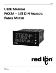
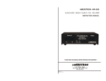
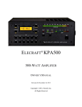
MANUALE INGLESE AMPLIFICATORE HVLA700AI REV.4
USER’S MANUAL rev.3.0
HVLA1K3
1300 WATTS 1.8 - 54 MHz SOLID STATE
AUTOMATIC LINEAR AMPLIFIER
HVLA1K3 USER’S MANUAL rev.3.0
INDEX
Section
Page
1 INTRODUCTION
- Important
- Precautions
2
2
2-3-4
2 SPECIFICATIONS
5
3 FRONT PANEL DESCRIPTION
6-7
4 REAR PANEL DESCRIPTION
8
5 PRELIMINARY PRECAUTIONS
- Amplifier location
- Connection to AC power supply
- Ground
- Antenna
9
9
9
9
9
6 Connection and operation with KENWOOD™ transceiver
- Important notes
10-11
11
7 Connection and operation with ICOM™ transceiver
- Important notes
12-13
12
8 ICOM ™ transceiver control cable schematic diagram
13
9 Connection and operation with YAESU™ transceiver
- Important notes
14-15
14
10 YAESU™ transceiver control cable schematic diagram
15
11 Connection and operation with K3 ELECRAFT™ transceiver
- Important notes
16-17
16
12 K3 ELECRAFT™ transceiver control cable schematic diagram
17
13 Protection circuits
18-19
14 TROUBLE SHOOTING
20
Addendum
Warranty
21
CE Declaration of Conformity
21
BLOCK DIAGRAM
22
Amphenol™ - Elecraft™ - Freescale™ - Icom™ - Yaesu™ - Kenwood™ are registered trademarks of
respective companies
Page 1
HVLA1K3 USER’S MANUAL rev.3.0
1
INTRODUCTION
Thank you for purchasing our next generation solid state linear amplifier model HVLA1K3. This
amplifier, with built-in power supply, provide up to 1300 watts RF input power with about
40 watts drive power on the 160-through 6 meter HF/VHF amateur radio bands, including the
WARC bands. This compact and lightweight amplifier employ the new generation of FREESCALE™
high ruggedness and efficiency 50V RF power LDMOS MOSFETs. The built-in decoder, which allow
you to forget about the band setting, and the electronic solutions adopted, give this amplifier the
most complete and very easy to operate in the market.
1.1 Important
Read the present manual carefully before attempting to operate the linear amplifier.
This manual contains important safety and operating instructions; warranty will be
invalidated in the case of non-observance of these instructions.
This manual may be subject to changes and updates.
1.2 Precautions
For your safety, and to minimize local EMI/RFI, the amplifier must be properly grounded before
operation.
Before connecting the amplifier verify that your mains supply is in accordance with the
specifications of the amplifier.
The AC power supply cord must be correctly rated and wired; if it’s not correctly rated and wired
there is a risk of fire or electric shock.
Before opening the cover of the amplifier make sure that AC power supply cord has been
disconnected. Take out AC power supply cord from the outlet.
Wait at least 1 minute for internal voltages to complete their discharge.
Page 2
HVLA1K3 USER’S MANUAL rev.3.0
Don’t turn ON the amplifier before connected the ANTENNA; a hazardous RF voltage may be
present on the antenna connector with no antenna connected.
Don’t disconnect an antenna during transmission; fire or electric shock may be possible.
Don’t expose the amplifier to rain, snow or any other liquids; fire or electric shock may be possible.
Don’t touch the case of the amplifier with damp or wet hands; electric shock may be possible.
The amplifier may cause interference and it can influence other electrical appliances. In such cases
the user must be take proper actions to reduce the interference.
Before opening the cover of the amplifier wait an hour after transmission; the heat generated by
the internal components of the amplifier may cause burns to your hands.
Don’t install the amplifier in a place without a very good ventilation; the poor heat dissipation
generated, in this situation, may damage the amplifier.
Page 3
HVLA1K3 USER’S MANUAL rev.3.0
Don’t obstruct the entries for cooling present in the cover of the amplifier; the poor heat
dissipation generated, in this situation, may damage the amplifier.
Don’t place the amplifier near walls or other obstacles; the poor heat dissipation generated, in this
situation, may damage the amplifier.
Don’t use the amplifier in locations with temperatures below 0°C or above +35°C.
Don’t place the amplifier in locations exposed to direct sunlight, dusty or damp.
Keep the original boxes and packaging materials; if factory service is required, the amplifier must
be shipped using the original boxes and packaging materials.
These symbol, present on the products, packaging, documentation or other, mean that used
electrical and electronics products should not be mixed with household waste (European Directive
2002/96/EC). Please consult your national legislation for treatment, recovery and recycling of this
type of products.
Page 4
HVLA1K3 USER’S MANUAL rev.3.0
2
SPECIFICATIONS
-Frequency Coverage:
1.8 to 54 MHz (all amateur frequencies WARC included)
-Operation Mode:
All modes
-Operating Frequency Band:
Automatic for KENWOOD™ - ICOM™ - YAESU™ - ELECRAFT™ transceiver
-Input Drive Power (typ.):
40 watts
-AMP Input VSWR (max.):
1.2:1
-VSWR Output Protection (typ.):
2:1
-Output Power:
1300 watts
-Efficiency (typ.):
75%
-PA Power Gain (typ.):
15 dB
-Output Filter type:
Low pass type
-Output Filter Band:
160 – 80 – 40 – 30/20 – 17/15 – 12/10 – 6 meter
-Harmonics Suppression:
HF = better than -45dB VHF = better than -60dB
-Third Order IMD:
-30 dBc
-IN/OUT Impedance:
50 ohms unbalanced Amphenol™ SO-239 connectors
-RF POWER TRANSISTOR:
MRFE6VP61K25 FREESCALE™ LDMOS MOSFETs
-Amplifier Circuitry:
Push pull AB class
-Cooling:
Dual speed forced air cooling by built-in dual ball bearing fan
-RX/TX Switching Time:
Lower than 10ms
-Power Supply Protections:
Short circuit, over current, over voltage, over temperature,
Power ON soft-start circuit
-Other Protections:
High antenna VSWR, wrong band, input overdrive, over temperature
-DC Internal Power Supplies:
50 VDC – 12 VDC
-AC Power Supply Range:
100 VAC to 240 VAC 50/60Hz
-Power Rating (max.):
2000VA
-Dimensions (max.):
34.5 x 33 x 18.5 cm - 13.6 x 13 x 7.3 in (W x D x H)
-Weight:
About 12 kg (26.5 lb)
Page 5
HVLA1K3 USER’S MANUAL rev.3.0
3
FRONT PANEL DESCRIPTION
1
BAND
This 9 position rotary switch select the manual (green LEDs “AUTO A” and “AUTO B” unlit) or auto
desired operating frequency band.
2
AUTO A
Green LED lights when operating frequency band is automatically controlled by KENWOOD™
transceiver; if not, the manual operating frequency band has been chosen.
3
AUTO B
Green LED lights when operating frequency band is automatically controlled by ICOM™ - YAESU™
or ELECRAFT™ transceiver; if not, the manual operating frequency band has been chosen.
4
160-80-40-30/20-17/15-12/10-6
Green LED lights according to the desired operating frequency band both for auto or manual
operating frequency band selection.
5
STBY – OUT
This 3 position rotary switch set in standby the amplifier in addition to set, the RF output power,
in low or high level. The amplifier is in standby mode (amp ON but not operating) when the green
LEDs, marked “LOW” and “HIGH”, are lit.
6
LOW
Green LED lights when RF low output power level has been chosen; if not, the amplifier is in
standby mode.
Page 6
HVLA1K3 USER’S MANUAL rev.3.0
7
HIGH
Green LED lights when RF high output power level has been chosen; if not, the amplifier is in
standby mode.
8
ANTENNA
This 2 position rotary switch select a primary antenna (ANT A) or a second antenna /dummy load
(ANT B).
9
ANT A
Green LED lights when the primary antenna has been chosen. This is the antenna output also
when the amplifier is turned OFF. Maximum allowed power in bypass mode is 200 watts.
10 ANT B
Green LED lights when a second antenna or a dummy load has been chosen. This function is
possible only when the amplifier is turned ON.
11 TX
Red LED lights when the amplifier is in transmit (operative) mode.
12 OVT
Red LED lights when the PA module reaches a high temperature and the auto-reset protection
circuit has worked.
13 FAULT
Red LED lights when a high antenna VSWR (typ. 2:1) or a wrong band situation is detected to
indicate protection circuit has worked.
14 OVD
Red LED lights when input overdrive is detected to indicate protection circuit has worked.
15 ON
Red LED lights when power is turned ON.
16 ON / OFF
Main power switch to turn AC power ON and OFF.
17 METER
2.4” colour TFT screen reading the RF output power and VSWR antenna level.
Note1: never exceed the value of the RF output power level indicated as “HIGH” in the
reading bar.
Note2: never exceed the VSWR antenna level indicated as “HIGH” ; ideal an indication to the
middle (or as low as possible) in the reading bar.
Page 7
HVLA1K3 USER’S MANUAL rev.3.0
4
REAR PANEL DESCRIPTION
1
AUTO B
D-SUB (9 pin) male connector for control cable from ICOM™ - YAESU™- ELECRAFT™ transceiver.
2
RELAY (Opto-Isolated input)
RCA female connector for control cable from KENWOOD™ transceiver (or other brand). The center
pin is to be shorted to ground through the relay circuit of the transceiver; the total keying current
is under 10 mA.
Note: when you use this connector with no KENWOOD™ transceiver, the amplifier will
not be operative in auto mode.
3
AUTO A
D-SUB (9 pin) male connector for control cable from KENWOOD™ RS-232 COM port transceiver.
4
POWER SUPPLY
IEC type C14 AC Mains Socket. Socket for the AC power cord with two 10A (5x20 fast type) fuses
included (socket is EMI filtered).
5
RF IN
Amphenol™ SO-239 RF input connector. Connect the coax jumper cable from the transceiver.
6
ANT A
Amphenol™ SO-239 primary RF output connector. Connect the coax cable to the primary antenna.
7
ANT B
Amphenol™ SO-239 second RF output connector. Connect the coaxial cable to the second antenna
or a dummy load.
8
GROUND
Ground terminal.
Page 8
HVLA1K3 USER’S MANUAL rev.3.0
5
PRELIMINARY PRECAUTIONS
Before you start to install the amplifier, fully read this manual. Carefully remove the amplifier from
its boxes and packaging materials and inspect for physical damage incurred during shipping.
If any damage is found contact immediately your supplier.
Keep the original boxes and packaging materials; if factory service is required, the amplifier must
be shipped using the original boxes and packaging materials.
5.1 Amplifier location
The amplifier must be located in a cool and dry area with large space around the amplifier to allow
good ventilation to all surfaces and free flow of the air. Don’t obstruct the entries for cooling
present in the cover of the amplifier and don’t place the amplifier near walls or other obstacles.
Reduced airflow conditions can severely damage the amplifier ! ! !
5.2 Connection to AC power supply
The amplifier features an internal high efficiency switching power supply. It accepts the wide AC
line voltage ranging from 100 VAC to 240 VAC 50/60 Hz automatically. Before connecting the
amplifier verify that your mains supply is in accordance with the specifications of the amplifier. The
amplifier must be connected directly to the mains supply with the supplied AC power cord, without
the use of adaptors or other accessories. Before connecting the amplifier to your mains supply, be
sure that the supply is correctly wired and rated for the current drawn by the amplifier (up to 10
A). The installation leads must be at least 1,5 mm² or #15 AWG. If you connect the amplifier to a
different mains outlet, be sure that you check it, too.
5.3 Ground
Connect the ground stud of the amplifier (on the rear panel, marked “GROUND”) to the station’s
grounding system. A proper ground connection will result in reduced RF strays or noises and avoid
points of RF high voltages during transmission on metallic objects that may come into contact with
the operator.
5.4 Antenna
The amplifier is designed for use with antennas that present an impedance of 50 ohms at the
operating frequency. Connect a coaxial cable from the amplifier output (on the rear panel, marked
“ANT A” and “ANT B”) with a PL-259 plug to the antenna for the respective band. We
recommend, that you use RG213 or better coaxial cable. If antenna VSWR is 1.8:1 higher at
operating band , the antenna has to be adjusted for lower VSWR; in this condition an antenna
tuner must be inserted.
Page 9
HVLA1K3 USER’S MANUAL rev.3.0
6
CONNECTION AND OPERATION with KENWOOD™ transceiver
6.1 Connect AC power cord and coax cables as mentioned on page 9. Run a shielded cable from
the transceiver “REMOTE” connector to the amplifier rear panel “RELAY” phono (RCA) female
connector. The phono (RCA) female connector center pin is to be shorted to ground through the
relay circuit of the transceiver; the total keying current is under 10 mA. If these connections are
not made, the amplifier will not go into TX (amplification) mode. For a temporary check to the
amplifier, ground the “RELAY” center pin by inserting a RCA plug whose center pin has been
soldered to the outer case of the plug with a small piece of wire.
6.2 Connect a right DSUB (9pin) female – DSUB (9pin) female high quality shielded cable, from
RS-232 COM port of your transceiver to the amplifier rear panel “AUTO A” D-SUB (9pin) male
connector.
6.3 Set RS-232 COM port of your transceiver to 19200 bps and 1 stop bit.
6.4 Use a short 50 ohms coaxial cable, type RG58 or equivalent for the connection from the RF
output of the transceiver to the amplifier rear panel “RF IN” SO-239 connector.
6.5 Keeping the main power switch OFF, check the VSWR of your antenna by keeping the
transceiver to TX mode (CW, FM or RTTY mode). Monitor the VSWR with an external SWR/power
meter. If VSWR is 1.8:1 or higher, the antenna has to be adjusted for lower VSWR. As an
alternative, an antenna tuner may be inserted.
6.6 Turn the main power switch ON. Turn the “BAND” rotary switch to “AUTO A” position (green
LED “AUTO A” will light). Turn the “ANTENNA” rotary switch to a specific antenna, if necessary.
Turn the “STBY-OUT” rotary switch to the low output power position of the amplifier (green LED
“LOW” will light). Now, key the transceiver with the carrier level set relatively low (such as 10
watts) and monitor the antenna VSWR and the output power with an external power meter.
6.7 Now increase the drive level to nearly 40 watts to achieve maximum carrier output power of
more 1000 watts from the amplifier. Monitor the output power and if the antenna VSWR stays
constant (as higher RF current flow, some antennas may show a changed VSWR due to heated
components such as trap coils).
6.8 With a high power transceiver in SSB mode, you can overdrive the amplifier in a distorted
output signal. This can occur if you speak too loud or if you set the microphone (or compressor)
gain too high. Speak into the microphone properly to reduce the possibilities of spattering into the
neighborhood. You can reduce the RF output power, also.
6.9 Protection circuits may work during operation depending on the conditions. For more details
on this protection circuits, see section 13. PROTECTION CIRCUITS.
Page
10
HVLA1K3 USER’S MANUAL rev.3.0
6.10 IMPORTANT NOTES:
-
For high duty cycle transmissions like RTTY, it is recommended that you use the low output
power position (green LED “LOW” lit up).
For normal cycle transmissions like SSB, you can use the high output power position (green
LED “HIGH” lit up).
-
Due to the relatively low switching time of the TX-RX relays, we don’t guarantee the use of
the transmission high-speed CW Full Break-in mode when the amplifier is in use.
-
Required drive power is slightly less than 40 watts to obtain the full over 1000 watts output
power. Do not attempt to operate with excessive drive power from a high power transceiver.
-
Absolutely never rotate the “BAND”, STBY-OUT” and “ANTENNA” rotary switches
during operation.
-
Use of the amplifier with an incorrect band filter selected, or without a welladjusted antenna, may damage the amplifier.
Page
11
HVLA1K3 USER’S MANUAL rev.3.0
7
CONNECTION AND OPERATION with ICOM™ transceiver
This section explains a one-antenna connected to an ICOM™ transceiver provided of “Band
Voltage Output” pin.
7.1 Connect AC power cord and coax cables as mentioned on page 9. Run a shielded control
cable (see page nr.13) from the remote terminals (transceiver producers give different names to
this output; please, check your transceiver’s manual) to the amplifier rear panel “AUTO B” D-SUB
(9 pin) male connector.
7.2 Use a short 50 ohms coaxial cable, type RG58 or equivalent for the connection from the RF
output of the transceiver to the amplifier rear panel “RF IN” SO-239 connector.
7.3 Keeping the main power switch OFF, check the VSWR of your antenna by keeping the
transceiver to TX mode (CW, FM or RTTY mode). Monitor the VSWR with an external SWR/power
meter. If VSWR is 1.8:1 or higher, the antenna has to be adjusted for lower VSWR. As an
alternative, an antenna tuner may be inserted.
7.4 Turn the main power switch ON. Turn the “BAND” rotary switch to “AUTO B” position (green
LED “AUTO A” will light). Turn the “ANTENNA” rotary switch to a specific antenna, if necessary.
Turn the “STBY-OUT” rotary switch to the low output power position of the amplifier (green LED
“LOW” will light). Now, key the transceiver with the carrier level set relatively low (such as 10
watts) and monitor the antenna VSWR and the output power with an external power meter.
7.5 Now increase the drive level to nearly 40 watts to achieve maximum carrier output power of
more 1000 watts from the amplifier. Monitor the output power and if the antenna VSWR stays
constant (as higher RF current flow, some antennas may show a changed VSWR due to heated
components such as trap coils).
7.6 With a high power transceiver in SSB mode, you can overdrive the amplifier in a distorted
output signal. This can occur if you speak too loud or if you set the microphone (or compressor)
gain too high. Speak into the microphone properly to reduce the possibilities of spattering into the
neighborhood. You can reduce the RF output power, also.
7.7 Protection circuits may work during operation depending on the conditions. For more details
on this protection circuits, see section 13. PROTECTION CIRCUITS.
7.8 IMPORTANT NOTES:
-
For high duty cycle transmissions like RTTY, it is recommended that you use the low output
power position (green LED “LOW” lit up). For normal cycle transmissions like SSB, you can
use the high output power position (green LED “HIGH” lit up).
-
Due to the relatively low switching time of the TX-RX relays, we don’t guarantee the use of
the transmission high-speed CW Full Break-in mode when the amplifier is in use.
-
Required drive power is slightly less than 40 watts to obtain the full over 1000 watts output
power. Do not attempt to operate with excessive drive power from a high power transceiver.
Page
12
HVLA1K3 USER’S MANUAL rev.3.0
-
Absolutely never rotate the “BAND”, STBY-OUT” and “ANTENNA” rotary switches
during operation.
-
Use of the amplifier with an incorrect band filter selected, or without a welladjusted antenna, may damage the amplifier.
8
ICOM™ TRANSCEIVER CONTROL CABLE SCHEMATIC DIAGRAM
This section explains the electrical connections to control the amplifier with an ICOM™ transceiver
provided of “Band Voltage Output” pin.
“ AUTO B” D-SUB (9 pin) male connector
NOTE: as viewed from rear panel
D-SUB (9 pin) NR. :
CONNECT TO ICOM™ REMOTE TERMINALS NAMED:
(ACC2 7 pole DIN - ACC 13 pole DIN)
1
2
3
4
5
6
7-8
9
N.C.
N.C.
N.C.
N.C.
BAND
SEND (HSEND)
NOTE: SOLDER TOGETHER D-SUB (9 pin) PINS
GND (GROUND)
Note: as cable use a two wire plus shield quality shielded cable.
Page
13
HVLA1K3 USER’S MANUAL rev.3.0
9
CONNECTION AND OPERATION with YAESU™ transceiver
This section explains a one-antenna connected to a YAESU™ transceiver provided of “Band Data”
output pins.
9.1 Connect AC power cord and coax cables as mentioned on page 9. Run a shielded control
cable (see page nr.15) from the remote terminals (transceiver producers give different names to
this output; please, check your transceiver’s manual) to the amplifier rear panel “AUTO B” D-SUB
(9 pin) male connector.
9.2 Use a short 50 ohms coaxial cable, type RG58 or equivalent for the connection from the RF
output of the transceiver to the amplifier rear panel “RF IN” SO-239 connector.
9.3 Keeping the main power switch OFF, check the VSWR of your antenna by keeping the
transceiver to TX mode (CW, FM or RTTY mode). Monitor the VSWR with an external SWR/power
meter. If VSWR is 1.8:1 or higher, the antenna has to be adjusted for lower VSWR. As an
alternative, an antenna tuner may be inserted.
9.4 Turn the main power switch ON. Turn the “BAND” rotary switch to “AUTO B” position (green
LED “AUTO B” will light). Turn the “ANTENNA” rotary switch to a specific antenna, if necessary.
Turn the “STBY-OUT” rotary switch to the low output power position of the amplifier (green LED
“LOW” will light). Now, key the transceiver with the carrier level set relatively low (such as 10
watts) and monitor the antenna VSWR and the output power with an external power meter.
9.5 Now increase the drive level to nearly 40 watts to achieve maximum carrier output power of
more 1000 watts from the amplifier. Monitor the output power and if the antenna VSWR stays
constant (as higher RF current flow, some antennas may show a changed VSWR due to heated
components such as trap coils).
9.6 With a high power transceiver in SSB mode, you can overdrive the amplifier in a distorted
output signal. This can occur if you speak too loud or if you set the microphone (or compressor)
gain too high. Speak into the microphone properly to reduce the possibilities of spattering into the
neighborhood. You can reduce the RF output power, also.
9.7 Protection circuits may work during operation depending on the conditions. For more details
on this protection circuits, see section 13. PROTECTION CIRCUITS.
9.8 IMPORTANT NOTES:
-
For high duty cycle transmissions like RTTY, it is recommended that you use the low output
power position (green LED “LOW” lit up).
For normal cycle transmissions like SSB, you can use the high output power position (green
LED “HIGH” lit up).
-
Due to the relatively low switching time of the TX-RX relays, we don’t guarantee the use of
the transmission high-speed CW Full Break-in mode when the amplifier is in use.
-
Required drive power is slightly less than 40 watts to obtain the full over 1000 watts output
power. Do not attempt to operate with excessive drive power from a high power transceiver.
Page
14
HVLA1K3 USER’S MANUAL rev.3.0
-
Absolutely never rotate the “BAND”, STBY-OUT” and “ANTENNA” rotary switches during
operation.
-
Use of the amplifier with an incorrect band filter selected, or without a well-adjusted
antenna, may damage the amplifier.
10 YAESU™ TRANSCEIVER CONTROL CABLE SCHEMATIC DIAGRAM
This section explains the electrical connections to control the amplifier with a YAESU™ transceiver
provided of “Band Data” pins.
“ AUTO B” D-SUB (9 pin) male connector
NOTE: as viewed from rear panel
D-SUB (9 pin) NR. :
CONNECT TO YAESU™ REMOTE TERMINALS NAMED:
(LINEAR – BAND DATA)
1
2
3
4
5
6
7
8
9
BAND DATA A
BAND DATA B
BAND DATA C
BAND DATA D
N.C.
TX GND
N.C.
N.C.
GND (GROUND)
Note: as cable use a five wire plus shield quality shielded cable.
Page
15
HVLA1K3 USER’S MANUAL rev.3.0
11 CONNECTION AND OPERATION with K3 ELECRAFT™ transceiver
This section explains a one-antenna connected to a K3 ELECRAFT™ transceiver provided
of D-SUBHD (15 pin) “ACC” connector.
11.1 Connect AC power cord and coax cables as mentioned on page 9. Run a shielded control
cable (see page nr.17) from K3 “ACC” Connector to the amplifier rear panel “AUTO B” D-SUB
(9 pin) male connector.
11.2 Use a short 50 ohms coaxial cable, type RG58 or equivalent for the connection from the RF
output of the transceiver to the amplifier rear panel “RF IN” SO-239 connector.
11.3 Keeping the main power switch OFF, check the VSWR of your antenna by keeping the
transceiver to TX mode (CW, FM or RTTY mode). Monitor the VSWR with an external SWR/power
meter. If VSWR is 1.8:1 or higher, the antenna has to be adjusted for lower VSWR. As an
alternative, an antenna tuner may be inserted.
11.4 Turn the main power switch ON. Turn the “BAND” rotary switch to “AUTO B” position (green
LED “AUTO B” will light). Turn the “ANTENNA” rotary switch to a specific antenna, if necessary.
Turn the “STBY-OUT” rotary switch to the low output power position of the amplifier (green LED
“LOW” will light). Now, key the transceiver with the carrier level set relatively low (such as 10
watts) and monitor the antenna VSWR and the output power with an external power meter.
11.5 Now increase the drive level to nearly 40 watts to achieve maximum carrier output power of
more 1000 watts from the amplifier. Monitor the output power and if the antenna VSWR stays
constant (as higher RF current flow, some antennas may show a changed VSWR due to heated
components such as trap coils).
11.6 With a high power transceiver in SSB mode, you can overdrive the amplifier in a distorted
output signal. This can occur if you speak too loud or if you set the microphone (or compressor)
gain too high. Speak into the microphone properly to reduce the possibilities of spattering into the
neighborhood. You can reduce the RF output power, also.
11.7 Protection circuits may work during operation depending on the conditions. For more details
on this protection circuits, see section 13. PROTECTION CIRCUITS.
11.8 IMPORTANT NOTES:
-
For high duty cycle transmissions like RTTY, it is recommended that you use the low output
power position (green LED “LOW” lit up).
For normal cycle transmissions like SSB, you can use the high output power position (green
LED “HIGH” lit up).
-
Due to the relatively low switching time of the TX-RX relays, we don’t guarantee the use of
the transmission high-speed CW Full Break-in mode when the amplifier is in use.
-
Required drive power is slightly less than 40 watts to obtain the full over 1000 watts output
power. Do not attempt to operate with excessive drive power from a high power transceiver.
Page
16
HVLA1K3 USER’S MANUAL rev.3.0
-
Absolutely never rotate the “BAND”, STBY-OUT” and “ANTENNA” rotary switches
during operation.
-
Use of the amplifier with an incorrect band filter selected, or without a welladjusted antenna, may damage the amplifier.
12 K3 ELECRAFT™ TRANSCEIVER CONTROL CABLE SCHEMATIC
DIAGRAM
This section explains the electrical connections to control the amplifier with a K3 ELECRAFT™
transceiver provided of D-SUBHD (15 pin) “ACC” connector.
“ AUTO B” D-SUB (9 pin) male connector
NOTE: as viewed from rear panel
D-SUB (9 pin) NR. :
CONNECT TO K3 ELECRAFT™ ACC CONNECTOR NAMED:
1
2
3
4
5
6
7
8
9
BAND0 OUT
BAND1 OUT
BAND2 OUT
BAND3 OUT
N.C.
KEYOUT-LP
N.C.
N.C.
GROUND
Note: as cable use a five wire plus shield quality shielded cable.
Page
17
HVLA1K3 USER’S MANUAL rev.3.0
13 PROTECTION CIRCUITS
There are many protection functions in this amplifier. If the amplifier has shut-down for some
reasons, before re-setting, correct the possible cause of the shut-down. Turn OFF the main AC
power switch once and back ON to reset. If the amplifier is operated in such a manner that
multiple protections work repeatedly over a long period of time, the amplifier can be seriously
damaged.
13.1 OVT (Over Temp)
Red LED marked “OVT” lights when the PA module reaches a high temperature and the protection
circuits has worked. Check for air intake blockages and air vent on cover. When the amplifier is in
protection mode, wait a ten minutes or more; the protection is auto-resetting.
13.2 FAULT (High antenna VSWR – Wrong Antenna/Band select)
Red LED marked “FAULT” lights when a high antenna VSWR (1.8:1 or higher), a wrong output
antenna has been selected or a wrong band situation is detected to indicate protection circuit has
worked. In case of high antenna VSWR, one solution is to reduce the drive power from the
transceiver or you may need to check that antenna VSWR is still OK. If the match cannot be
corrected, and the antenna system is not faulty, use an antenna tuner. In case of wrong band,
select the correct filter band.
If you have select a wrong band, two situations can happen:
a) if the selected filter cut-off frequency (or correspondent band) is lower than the one of the
transceiver, the protection will immediately shut-down the amplifier;
b) if the selected filter cut-off frequency (or correspondent band) is higher than the one of the
transceiver, is probable that the protection will not shut-down the amplifier but you will have an
emission full of unwanted harmonics.
13.3 OVD (Overdrive)
Red LED marked “OVD” lights when input overdrive is detected to indicate protection circuit has
worked in order to protect the input side of the power LDMOS. The solution is to reduce the input
drive power.
13.4 AC mains power supply FUSES
If either of the glass fuses (2x10A 5x20 fast type) on IEC type C14 AC mains socket fails, we
recommend do not replace the fuses and we invite you to consult the factory.
Fuses Holder
Page
18
HVLA1K3 USER’S MANUAL rev.3.0
13.5 Power Supply Unit (PSU) protections
The internal switching power supply unit features the following automatic protections:
- Soft start
- Short circuit
- Over current
- Over voltage
- Over temperature
A built-in green LED check its normal activity. If the green LED is OFF means that the PSU is in an
auto-protect condition, or AC mains power supply fuses are blown.
Another important feature of this PSU is its built-in PFC (Power Factor Corrector) circuit, with a
value better than 0,95 in according to the new European Rules on Energetic Efficiency.
Page
19
HVLA1K3 USER’S MANUAL rev.3.0
14 TROUBLE SHOOTING
The following table analyzes some common faults and their correction:
Fault
AC mains not
operating
Can’t enter
Transmit
mode
Possible Cause
a)AC fuses blown
b)AC cord not plugged
in
a)Control cable not
connected
b)Protection circuits ON
Over
temperature
lights
a)Internal temperature
high
Faults lights
a)High antenna VSWR
Over drive
lights
TVI, EMI
b)Wrong Band set
a)RF overdrive
a)RF overdrive
b)RF leakage from coax
cable, grounding wire,
AC power cord, etc.
Solution
a)Replace with new ones.
b)Plug in securely.
a)Check the control cable and connect properly.
b)Check the drive power, antenna VSWR, wrong band
selected, antenna selector A or B, high temperature.
Reset with AC power switch.
a)Ensure adequate airflow around the unit. Keep the
cooling fins unobstructed. Also check the VSWR of the
antenna system since a high VSWR increases the heat
dissipation by the amplifier, causing faster temperature
rise. Reduce drive level or duty cycle.
a)Check integrity of antenna and feedline connections.
Ensure antenna is resonant at the desired frequency.
b)Match the band correctly.
a)Decrease drive.
a)Decrease drive.
b)Insert common mode filters on antenna cable or AC
line. Add clamps on ferrite cores on various cables.
Page
20