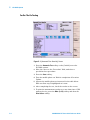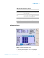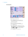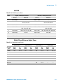
1
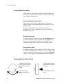
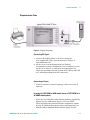
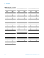
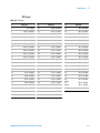
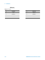
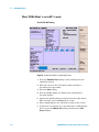
Agilent N9360A
Multi UE Tester
Quick Reference Guide
Agilent Technologies
Notices
© Agilent Technologies, Inc. 2008
Manual Part Number
No part of this manual may be reproduced
in any form or by any means (including
electronic storage and retrieval or translation into a foreign language) without prior
agreement and written consent from
Agilent Technologies, Inc. as governed by
United States and international copyright
laws.
N9360-90002
Edition
Third Edition, March 2008
Printed in Malaysia
Agilent Technologies Microwave Products
(Malaysia) Sdn. Bhd.
Bayan Lepas Free Industrial Zone
11900 Penang, Malaysia
Warranty
The material contained in this document is provided “as is,” and is subject to being changed, without notice,
in future editions. Further, to the
maximum extent permitted by applicable law, Agilent disclaims all warranties, either express or implied,
with regard to this manual and any
information contained herein, including but not limited to the implied
warranties of merchantability and fitness for a particular purpose. Agilent
shall not be liable for errors or for
incidental or consequential damages
in connection with the furnishing,
use, or performance of this document
or of any information contained
herein. Should Agilent and the user
have a separate written agreement
with warranty terms covering the
material in this document that conflict with these terms, the warranty
terms in the separate agreement
shall control.
Technology Licenses
The hardware and/or software described
in this document are furnished under a
license and may be used or copied only in
accordance with the terms of such license.
Restricted Rights Legend
computer software” as defined in FAR
52.227-19 (June 1987) or any equivalent
agency regulation or contract clause. Use,
duplication or disclosure of Software is
subject to Agilent Technologies’ standard
commercial license terms, and non-DOD
Departments and Agencies of the U.S.
Government will receive no greater than
Restricted Rights as defined in FAR
52.227-19(c)(1-2) (June 1987). U.S. Government users will receive no greater than
Limited Rights as defined in FAR 52.227-14
(June 1987) or DFAR 252.227-7015 (b)(2)
(November 1995), as applicable in any
technical data.
Safety Notices
CAUTION
A CAUTION notice denotes a hazard. It calls attention to an operating procedure, practice, or the like
that, if not correctly performed or
adhered to, could result in damage
to the product or loss of important
data. Do not proceed beyond a
CAUTION notice until the indicated
conditions are fully understood and
met.
WA R N I N G
A WARNING notice denotes a
hazard. It calls attention to an
operating procedure, practice, or
the like that, if not correctly performed or adhered to, could result
in personal injury or death. Do not
proceed beyond a WARNING
notice until the indicated conditions are fully understood and
met.
If software is for use in the performance of
a U.S. Government prime contract or subcontract, Software is delivered and
licensed as “Commercial computer software” as defined in DFAR 252.227-7014
(June 1995), or as a “commercial item” as
defined in FAR 2.101(a) or as “Restricted
N9360A Multi UE Tester Quick Reference Guide
ii
Preface
Thank-you for purchasing the Agilent N9360A mobile communciations
tester.
• Before using the tester, the user is advised to read this manual
carefully to ensure correct usage and also to fully utilize the tester
capability.
• This manual is a reference document and the user is advised to keep it
carefully for future reference.
• The manual includes the the tester operation, test procedures and
screen references.
• Refer to the N9360A Multi UE Tester Installation Guide for information
regarding installation and details of the tester. Refer also to the
N9360A W-CDMA Option User Manual and N9360A cdma2000 Option
User Manual for information about the test functions of the Wideband
Code Division Multiple Access (W-CDMA), and Code Division Multiple
Access (cdma2000).
Notation
The following notations are used in this manual:
• Softkey: indicates a softkey;
• [Screen Name]: indicates a screen name;
• Tester/tester : indicates the N9360A Multi UE Tester.
Notices
• The information contained in this manual is subjected to change with
notice.
• No part of this manual may be reproduced either mechanically,
electronically or otherwise, without permission from Agilent
Technologies, Inc.
Trademarks
• Ethernet is the registered trademark of the Xerox Corporation.
• EPSON is the registered trademark of the EPSON Corporation.
• Other product names and companies used herein are trademarks or
registered trademarks of their respective companies or Agilent
Technologies, Inc. For registered trademarks, the trademarks symbols
® and ™ are omitted in this manual.
• cdma2000 is a registered trademark of Telecommunication Industry
Association (TIA-USA).
N9360A Multi UE Tester Quick Reference Guide
iii
THIS PAGE IS INTENTIONALLY LEFT BLANK.
iv
N9360A Multi UE Tester Quick Reference Guide
Contents
Notation I-iii
Notices I-iii
Trademarks I-iii
1
Legal Information
Legal Information 1-2
Warranty 1-2
Technology Licenses 1-2
Restricted Rights Legend 1-2
Service And Support 1-3
Agilent On The Web 1-3
Agilent By Phone 1-3
2
Caution and Safety Requirements
Safety Information 2-2
Safety Summary 2-2
Safety Notices 2-2
Warning Label 2-2
General 2-3
When Operating The Tester 2-3
3
General Operation
Using a USB memory device 3-2
Using the Knob on the Front Panel 3-2
Using the Knob on the Front Panel 3-2
Preparation for Tests 3-3
GSM/W-CDMA/cdma2000 Mobile Phone Repair Process 3-4
4
GSM System
For Go/No-Go Testing 4-2
For Pinpointing Failures 4-3
For Troubleshooting 4-5
N9360A Multi UE Tester Quick Reference Guide
v
RF Channels 4-7
MS Power Control / Power Class 4-7
RX Level 4-9
RX Quality 4-10
5
W-CDMA System
For Go/No-Go Testing 5-2
For Pinpointing Failures 5-3
For Troubleshooting 5-4
UARFCN 5-5
Mobile Phone Maximum Output Power 5-5
6
cdma2000 System
When "CDMA Mode" is set to MC-1x mode 6-2
When "CDMA Mode" is set to 1xEV-DO mode 6-6
vi
N9360A Multi UE Tester Quick Reference Guide
1
Legal Information
Warranty 1-2
Technology Licenses
1-2
Restricted Rights Legend 1-2
Service And Support
1-3
Agilent On The Web
1-3
Agilent By Phone
1-3
Agilent Technologies
1-1
1
Legal Information
Legal Information
Warranty
The material contained in this document is provided “as is,” and
is subject to being changed, without notice, in future editions.
Further, to the maximum extent permitted by applicable law,
Agilent disclaims all warranties, either express or implied, with
regard to this manual and any information contained herein,
including but not limited to the implied warranties of
merchantability and fitness for a particular purpose. Agilent
shall not be liable for errors or for incidental or consequential
damages in connection with the furnishing, use, or performance
of this document or of any information contained herein.
Should Agilent and the user have a separate written agreement
with warranty terms covering the material in this document
that conflict with these terms, the warranty terms in the
separate agreement shall control.
Technology Licenses
The hardware and/or software described in this document are
furnished under a license and may be used or copied only in
accordance with the terms of such license.
Restricted Rights Legend
If software is for use in the performance of a U.S. Government
prime contract or subcontract, Software is delivered and
licensed as “Commercial computer software” as defined in
DFAR 252.227-7014 (June 1995), or as a “commercial item” as
defined in FAR 2.101(a) or as “Restricted computer software” as
defined in FAR 52.227-19 (June 1987) or any equivalent agency
regulation or contract clause. Use, duplication or disclosure of
Software is subject to Agilent Technologies’ standard
commercial license terms, and non-DOD Departments and
Agencies of the U.S. Government will receive no greater than
Restricted Rights as defined in FAR 52.227-19(c)(1-2)(June
1987). U.S. Government users will receive no greater than
Limited Rights as defined in FAR 52.227-14 (June 1987) or
DFAR 252.227-7015 (b)(2)(November 1995), as applicable in any
technical data.
1-2
N9360A Multi UE Tester Quick Reference Guide
Legal Information
1
Service And Support
Any adjustment, maintenance, or repair of this product must be
performed by qualified personnel. Contact your customer
engineer through your local Agilent Technologies Service
Center.
Agilent On The Web
You can find information about technical and professional
services, product support, and equipment repair and service on
the Web: http://www.agilent.com/
Double-click the link to Test & Measurement. Select your country
from the drop-down menus. The Web page that appears next has
contact information specific for your country
Agilent By Phone
If you do not have access to the Internet, call one of the
numbers in Table 1-1.
Table 1-1 Agilent Call Centers and Regional Headquarters
United States and Canada:
Test and Measurement Call Center
(800) 452 4844 (toll-free in US)
Europe:
(41 22) 780 8111
Japan:
Measurement Assistance Center
(81) 0426 56 7832
Latin America:
305 269 7548
Asia-Pacific:
(85 22) 599 7777
Manufacturing Address
Agilent Technologies Microwave Products (Malaysia) Sdn. Bhd.
Bayan Lepas Free Industrial Zone,
11900 Penang,
Malaysia.
N9360A Multi UE Tester Quick Reference Guide
1-3
1
Legal Information
THIS PAGE IS INTENTIONALLY LEFT BLANK
1-4
N9360A Multi UE Tester Quick Reference Guide
2
Caution and Safety Requirements
Safety Summary 2-2
Safety Notices 2-2
Warning Label 2-2
General 2-3
When Operating The Tester
2-3
Agilent Technologies
2-1
2
Caution and Safety Requirements
Safety Information
Safety Summary
The following general safety precautions must be observed
during all phases of operation of this instrument. Failure to
comply with these precautions or with specific warnings
elsewhere in this manual violates safety standards of design,
manufacture, and intended use of the instrument. Agilent
Technologies, Inc. assumes no liability for the customer's failure
to comply with these requirements.
Safety Notices
CAUTION
WA R N I N G
A CAUTION notice denotes a hazard. It calls attention to an
operating procedure, practice, or the like, that, if not correctly
performed or adhered to, could result in damage to the product or
loss of important data. Do not proceed beyond a CAUTION notice
until the indicated conditions are fully understood and met.
A WARNING notice denotes a hazard. It calls attention to an
operating procedure, practice, or the like that, if not correctly
performed or adhered to, could result in personal injury or death.
Do not proceed beyond a WARNING notice until the indicated
conditions are fully understood and met.
Warning Label
A warning label is stuck on the front panel of the Tester.
Do not remove, damage or modify the warning label.
2-2
N9360A Multi UE Tester Quick Reference Guide
Caution and Safety Requirements
2
General
WA R N I N G
WA R N I N G
The protection provided by the N9360A tester may be impaired if
the tester is used in a manner not specified by Agilent or the
instructions on the display are not followed.
DO NOT INSTRUMENT COVERS. Operating personnel must not
remove any instrument covers. Component replacement and
internal adjustments must be made only by qualified service
personnel. Products that appear damaged or defective should be
made inoperative and secured against unintended operation until
they can be repaired by a qualified service personnel.
When Operating The Tester
CAUTION
CAUTION
Make sure that the input signal level does not exceed the maximum
level allowed. Tester failure may result otherwise.
Do not turn off the Line switch on the rear panel of the Tester while
the LINE LED on the front panel of the Tester is lit in green.
Otherwise, Tester failure may occur.
N9360A Multi UE Tester Quick Reference Guide
2-3
2
Caution and Safety Requirements
THIS PAGE IS INTENTIONALLY LEFT BLANK.
2-4
N9360A Multi UE Tester Quick Reference Guide
3
General Operation
Using a USB memory device 3-2
Using the Knob on the Front Panel 3-2
Preparation for Tests 3-3
GSM/W-CDMA/cdma2000 Mobile Phone Repair Process
Agilent Technologies
3-4
3-1
3
General Operation
Using a USB memory device
A USB memory device can be used to save and recall the test
procedures, to update the firmware of the Tester, and to save
screen images as image files.
Saving and Recalling Test Procedures:
All settings for Automatic Test, Manual Test, TX Analyzer,
Signal Generator, and Configuration can be saved into a test
procedure file.
To save a test procedure or to recall a pre-defined test
procedure, go to the [Configuration] screen, then the [File
Management] screen.
Updating the Firmware:
To update firmware of the Tester, press the FW Update softkey to
go to the [Firmware Update] screen on the [Configuration]
screen obtained from the [Top Menu] screen. Refer to the
“Firmware Update Screen” in the User's Guide for details.
Saving a Screen Image:
To enable this function, it is required to set the “Printer” input
field on the [Configuration] screen to USB Memory. Then, to save
a screen image into a USB memory device, press the Print Screen
softkey. The file format is PNG (Portable Network Graphics).
Using the Knob on the Front Panel
3-2
1. Rotate the knob to place
the cursor next to the input
field where you want to
change.
2. Push the knob to select
the field where you placed
the cursor.
3. Rotate the knob to
change the value in the
field.
4. Push the knob to set the
value.
N9360A Multi UE Tester Quick Reference Guide
General Operation
3
Preparation for Tests
Figure 3-1 Typical Test Setup
Connecting RF Signal:
1 Connect the mobile phone to the Tester using the
user-supplied RF Cable, optional Antenna Coupler, or
optional Shield Case.
2 On the [Loss] screen obtained from the [Initial],
[Configuration] and [Configuration: Test Condition] screens,
set the “Loss” field to On and enter the appropriate loss
values for each Radio System or Band in the “RF In” and “RF
Out” fields depending on the RF connection.
Connecting a Printer:
• Connect a printer to print a hardcopy of the test results if
required.
Inserting the TEST SIM for GSM mobile phone or TEST USIM for a
W-CDMA mobile phone:
• Insert the Test SIM (Subscriber Identity Module) supplied by
Agilent into the GSM mobile phone or the test USIM
(Universal Subscriber Identity Module) supplied by Agilent
into the W-CDMA mobile phone before performing any test.
• GSM/W-CDMA/cdma2000 Mobile Phone Repair Process
N9360A Multi UE Tester Quick Reference Guide
3-3
3
General Operation
GSM/W-CDMA/cdma2000 Mobile Phone Repair Process
Figure 3-2 Mobile Phone Repair Process
A typical GSM, W-CDMA and cdma2000 mobile phone repair
process at service centers is basically divided into two
processes, Incoming Inspection and Mechanical & Module
Repair. In each process, you can perform the following tests
with the Agilent N9360A Multi UE Tester.
Table 3-1 Mobile Phone Repair Function
3-4
Process
Test
Agilent N9360A Multi UE
Tester Function
Incoming Inspection
Go/No-Go Test
Automatic Test
Module Repair
Pinpointing Failures
Automatic Test
Troubleshooting
Manual Test
Adjustment
TX Analyzer, Signal Generator
Final Test
(Go/No-Go Test)
Automatic Test
N9360A Multi UE Tester Quick Reference Guide
4
GSM System
For Go/No-Go Testing 4-2
For Pinpointing Failures 4-3
For Troubleshooting 4-5
RF Channels 4-7
MS Power Control / Power Class
RX Level 4-9
RX Quality 4-10
4-7
Agilent Technologies
4-1
4
GSM System
For Go/No-Go Testing
Figure 4-1 [Automatic Test: Stand-by] Screen
1 Press the Automatic Test softkey on the [Initial] screen in GSM
system.
2 Move the cursor to the “Procedure” field, and select a
pre-defined test procedure.
3 Press the Start softkey.
4 Turn the mobile phone on. Wait for the completion of
Location Update.
5 Operate the mobile phone as instructed in the table below.
Each test flow step is highlighted as it runs.
6 After completing the test, check the results on the screen.
7 To print the test results or to save them into a USB memory
device, press the More (1 of 2) softkey and then the Print Screen
softkey.
4-2
N9360A Multi UE Tester Quick Reference Guide
GSM System
4
Table 4-2 GSM Automatic test sequence
Step
Action needed
Location Update
Wait until the Location Update is complete.
MS Call
Dial an arbitrary number and press the Off Hook key
on the mobile phone.
Talk
Talk to the mobile phone to judge its loop back sound
quality and press the Pass or Fail softkey.
RF Test
Wait until the RF test is complete.
MS Release
Finish the call from the mobile phone.
BS Call
Respond to the call on the mobile phone.
BS Release
Wait until the call is finished from the Tester.
For Pinpointing Failures
Figure 4-2 [Automatic Test: Stand-by] Screen
1 Perform the steps described in “For Go/No-Go Testing.”
2 Press the Screen>> softkey to set screen mode to Detail or
Value.
N9360A Multi UE Tester Quick Reference Guide
4-3
4
GSM System
3 Rotate the knob to place the cursor in one of the Pass/Fail
cells on the detail screen or test result cells on the value
screen. Then, press the knob.
4 One of the following measurement result screens is displayed
according to your selection in step 3.
• To print the measurement results or to save them into a
USB memory device, press the Print Screen softkey.
• In the graphical display, you can use the marker function
to read data points by rotating the knob.
• The zoom function is available on the power ramp graph
display by pressing the Zoom Off/On softkey.
Peak TX
Power
Burst Timing
Power Ramp
Phase Error
Frequency Error
Sensitivity
RX Quality
RX Level
Figure 4-3 Various [Automatic Test: Stand-by] Screens
5 To display other measurement result screens or to finish
analysis, press the Return softkey to display the previous
screen.
4-4
N9360A Multi UE Tester Quick Reference Guide
GSM System
4
For Troubleshooting
Figure 4-4 [Manual Test (GSM): Stand-by] Screen
1 Press the Manual Test softkey on the [Initial] screen.
2 Move the cursor to the “Procedure” field and select a
pre-defined test procedure.
3 Turn the mobile phone on.
4 Wait for the completion of Location Update.
5 Press the BS Call softkey and respond to the call on the
mobile phone when it is called. Or, dial an arbitrary number
and press the Off Hook key on the mobile phone to start the
MS Call.
6 To start measurement while the left screen is displayed, refer
to step 7. For detailed measurement at each measurement
item, refer to step 8.
N9360A Multi UE Tester Quick Reference Guide
4-5
4
GSM System
Peak TX Power/ Burst
Timing/ Power Ramp
Phase Error
Frequency Error
Sensitivity
RX Quality
RX Level
Spectrum
Monitor
Figure 4-5 Various [Manual Test (GSM): Stand-by] Screens
7 While “Connection” is highlighted in the test flow, press the
Trigger softkey to start single measurement or the Trigger
Sing/Cont softkey to start continuous measurement. Press the
Trigger Sing/Cont softkey again to terminate the continuous
measurement.
8 Place the cursor at one of the groups of the test items and
press the knob or press the Spectrum Monitor softkey to display
a measurement result screen according to your selection.
Then, press the Trigger softkey to start single measurement or
Trigger Sing/Cont softkey to start continuous measurement.
4-6
N9360A Multi UE Tester Quick Reference Guide
GSM System
4
Press the Trigger Sing/Cont softkey again to terminate the
continuous measurement.
9 In the graphical display, the marker function is available to
read the data points by rotating the knob. On the power ramp
graph display, the zoom function is also available.
10 To display other measurement result screens, press the
Return softkey to display the previous screen. To end the
entire test, press the Release softkey to start the BS Release,
or press the On Hook key on the mobile phone to finish the
MS Release.
RF Channels
Table 4-3 GSM RF channel frequencies and channel number
GSM850
GSM900
DCS1800
PCS1900
Uplink
824.2 to 848.8 MHz
890.2 to 914.8 MHz
876.2 to 889.8 MHz
1710.2 to 1784.8 MHz
1850.2 to 1909.8 MHz
Downlink
869.2 to 893.8 MHz
935.2 to 959.8 MHz
921.2 to 934.8 MHz
1805.2 to 1879.8 MHz
1930.2 to 1989.8 MHz
ARFCN
128 to 251
0 to 124
955 to 1023
512 to 885
512 to 810
NOTE
GSM900 includes P-GSM, E-GSM, and R-GSM Bands.
MS Power Control / Power Class
Table 4-4 GSM Power Control levels
GSM 850 / 900
DCS1800
PCS1900
Power Control
Level
Nominal Power
(dBm)
Power Control
Level
Nominal Power
(dBm)
Power Control
Level
Nominal Power
(dBm)
0
39
29
36
30
33
3
37
30
34
31
32
4
35
31
32
0
30
5
33
0
30
1
28
6
31
1
28
2
26
N9360A Multi UE Tester Quick Reference Guide
4-7
GSM System
4
Table 4-4 GSM Power Control levels
GSM 850 / 900
DCS1800
PCS1900
Power Control
Level
Nominal Power
(dBm)
Power Control
Level
Nominal Power
(dBm)
Power Control
Level
Nominal Power
(dBm)
7
29
2
26
3
24
8
27
3
24
4
22
9
25
4
22
5
20
10
23
5
20
6
18
11
21
6
18
7
16
12
19
7
16
8
14
13
17
8
14
9
12
14
15
9
12
10
10
15
13
10
10
11
8
16
11
11
8
12
6
17
9
12
6
13
4
18
7
13
4
14
2
19
5
14
2
15
0
15
0
GSM 850 / 900
DCS1800
PCS1900
Power Class
Max Power
Control Level
Power Class
Max Power
Control Level
Power Class
Max Power
Control Level
1
N/A
1
0
1
0
2
2
2
3
2
3
3
3
3
29
3
30
4
5
5
7
4-8
N9360A Multi UE Tester Quick Reference Guide
GSM System
4
RX Level
Table 4-5 RX levels
#
RX Level
#
RX Level
#
RX Level
0
≤−110 dBm
22
–89 to –88 dBm
44
–67 to –66 dBm
1
–110 to –109 dBm
23
–88 to –87 dBm
45
–66 to –65 dBm
2
–109 to –108 dBm
24
–87 to –86 dBm
46
–65 to –64 dBm
3
–108 to –107 dBm
25
–86 to –85 dBm
47
–64 to –63 dBm
4
–107 to –106 dBm
26
–85 to –84 dBm
48
–63 to –62 dBm
5
–106 to –105 dBm
27
–84 to –83 dBm
49
–62 to –61 dBm
6
–105 to –104 dBm
28
–83 to –82 dBm
50
–61 to –60 dBm
7
–104 to –103 dBm
29
–82 to –81 dBm
51
–60 to –59 dBm
8
–103 to –102 dBm
30
–81 to –80 dBm
52
–59 to –58 dBm
9
–102 to –101 dBm
31
–80 to –79 dBm
53
–58 to –57 dBm
10
–101 to –100 dBm
32
–79 to –78 dBm
54
–57 to –56 dBm
11
–100 to –99 dBm
33
–78 to –77 dBm
55
–56 to –55 dBm
12
–99 to –98 dBm
34
–77 to –76 dBm
56
–55 to –54 dBm
13
–98 to –97 dBm
35
–76 to –75 dBm
57
–54 to –53 dBm
14
–97 to –96 dBm
36
–75 to –74 dBm
58
–53 to –52 dBm
15
–96 to –95 dBm
37
–74 to –73 dBm
59
–52 to –51 dBm
16
–95 to –94 dBm
38
–73 to –72 dBm
60
–51 to –50 dBm
17
–94 to –93 dBm
39
–72 to –71 dBm
61
–50 to –49 dBm
18
–93 to –92 dBm
40
–71 to –70 dBm
62
–49 to –48 dBm
19
–92 to –91 dBm
41
–70 to –69 dBm
63
≥−48 dBm
20
–91 to –90 dBm
42
–69 to –68 dBm
21
–90 to –89 dBm
43
–68 to –67 dBm
N9360A Multi UE Tester Quick Reference Guide
4-9
GSM System
4
RX Quality
Table 4-6 RX Quality
#
RX Quality
#
RX Quality
0
<0.2 %
4
1.6 to 3.2 %
1
0.2 to 0.4 %
5
3.2 to 6.4 %
2
0.4 to 0.8 %
6
6.4 to 12.8 %
3
0.8 to 1.6 %
7
>12.8 %
4-10
N9360A Multi UE Tester Quick Reference Guide
5
W-CDMA System
For Go/No-Go Testing 5-2
For Pinpointing Failures 5-3
For Troubleshooting 5-4
UARFCN 5-5
Mobile Phone Maximum Output Power 5-5
Agilent Technologies
5-1
5
W-CDMA System
For Go/No-Go Testing
Figure 5-1 [Automatic Test: Stand-by] Screen
1 Press the Automatic Test softkey on the [Initial] screen for
W-CDMA system.
2 Move the cursor to the “Procedure” field, and select a
pre-defined test procedure.
3 Press the Start softkey.
4 Turn the mobile phone on. Wait for completion of Location
Update.
5 Operate the mobile phone as instructed in the table below.
Each test flow step is highlighted as it runs.
6 After completing the test, check the results on the screen.
7 To print the measurement results or to save them into a USB
memory device, press the More (1 of 2) softkey and then the
Print Screen softkey.
5-2
N9360A Multi UE Tester Quick Reference Guide
W-CDMA System
5
Table 5-1 W-CDMA Automatic Test Sequence
Step
Action needed
Location Update
Wait until the Location Update is completed.
MS Call
Dial an arbitrary number and press the Off Hook key
on the mobile phone.
Talk
Talk to the mobile phone to judge its loop back sound
quality and press the Pass or Fail softkey.
MS Release
Finish the call from the mobile phone.
BS Call (AMR)
Respond to the call on the mobile phone.
BS Call (RMC)
The mobile phone automatically responds to the call.
RF Test
Wait until the RF test is completed.
BS Release
Wait until the call is finished from the Tester.
For Pinpointing Failures
Figure 5-2 [Automatic Test: Stand-by] Screen
1 Perform the steps described in “For Go/No-Go Testing.”
2 Press the Screen>> softkey to set screen mode to Value.
3 Check the values of the measurement results.
N9360A Multi UE Tester Quick Reference Guide
5-3
5
W-CDMA System
For Troubleshooting
Figure 5-3 [Manual Test: Stand-by] Screen
1 Press the Manual Test softkey on the [Initial] screen.
2 Move the cursor to the “Procedure” field and select a
pre-defined test procedure.
3 Turn the mobile phone on.
4 Wait for the completion of Location Update.
5 Select “RMC” for BS Call at the “BS Call” input field.
6 Press the BS Call softkey.
7 While “Connection (RMC)” is highlighted in the test flow,
press the Trigger softkey to start single measurement or the
Trigger Sing/Cont softkey to start continuous measurement.
Press the Trigger Sing/Cont softkey again to terminate
continuous measurement.
8 Press the Release softkey to finish the Test.
5-4
N9360A Multi UE Tester Quick Reference Guide
W-CDMA System
5
UARFCN
Table 5-2 W-CDMA Frequency Band
Band
Uplink ; mobile phone transmit
Downlink ; mobile phone receive
General
Additional
General
Additional
I
9612 to 9888
—
10562 to 10838
—
II
9262 to 9538
12, 37, 62, 87, 112, 137, 62, 187,
212, 237, 262, 287
9662 to 9938
412, 437, 462, 487, 512, 537, 562,
587, 612, 637, 662, 687
III
8562 to 8913
—
9037 to 9388
—
IV
8562 to 8763
1162, 1187, 1212, 1237,1262,
1287, 1312, 1337, 1362
10562 to 10763
1462, 1487, 1512, 1537, 1562, 1587,
1612, 1637, 1662
V
4132 to 4233
782, 787, 807, 812, 837, 862
4357 to 4458
1007, 1012, 1032, 1037, 1062, 1087
VI
4162 to 4188
812, 837
4387 to 4413
1037, 1062
VIII
2700 to 2875
—
2925 to 3100
—
IX
8750 to 8924
—
9225 to 9399
—
Mobile Phone Maximum Output Power
Table 5-3 UE Maximum Output Power
Power Class 1
Power Class 2
Power Class 3
Power Class 4
Operating
Band
Power
(dBm)
Tol.
(dB)
Power
(dBm)
Tol.
(dB)
Power
(dBm)
Tol.
(dB)
Power
(dBm)
Tol.
(dB)
Band I
+33
+1/–3
+27
+1/–3
+24
+1/–3
+21
+2/–2
Band II
+24
+1/–3
+21
+2/–2
Band III
+24
+1/–3
+21
+2/–2
Band IV
+24
+1/–3
—
—
Band V
+24
+1/–3
23
+2/–2
Band VI
+24
+1/–3
+23
+2/–2
Band VIII
+24
+1/–3
—
—
N9360A Multi UE Tester Quick Reference Guide
5-5
5
W-CDMA System
THIS PAGE IS INTENTIONALLY LEFT BLANK.
5-6
N9360A Multi UE Tester Quick Reference Guide
6
cdma2000 System
When "CDMA Mode" is set to MC-1x mode 6-2
When "CDMA Mode" is set to 1xEV-DO mode 6-6
Agilent Technologies
6-1
6
cdma2000 System
When "CDMA Mode" is set to MC-1x mode
For Go/No-Go Testing
Figure 6-1 [Auto Test (MC-1x): Stand-by] Screen
1 Press the Automatic Test softkey on the [Initial] screen in
cdma2000 system
2 Move the cursor to the "Procedure" field, and select a
pre-defined test procedure.
3 Press the Start softkey.
4 Turn the mobile phone on. Wait for the completion of
Location Update.
5 Operate the mobile phone as instructed in the table below.
Each test flow step is highlighted as it runs.
6 After completing the test, check the results on the screen.
7 To print the test results or to save them into a USB memory
device, press the More(1 of 2) softkey and then the Print
Screen softkey.
6-2
N9360A Multi UE Tester Quick Reference Guide
cdma2000 System
6
Table 6-1 cdma2000 Automatic Test Sequence
Step
Action Needed
Location Update
Wait until the Location Update is complete.
MS Call (Talk)
Dial an arbitrary number and press the Off
Hook key on the mobile phone.
Talk
Talk to the mobile phone to judge its loop
back sound quality and press the Pass or Fail
softkey.
MS Release
Finish the call from the mobile phone.
BS Call (Talk)
Respond to the call on the mobile phone.
BS Call (RF Test)
The mobile phone automatically responds to
the call.
RF Test
Wait until the RF test is completed.
Softer Handoff
Wait until the Softer Handoff is completed.
BS Release
Wait until the call is finished from the Tester.
N9360A Multi UE Tester Quick Reference Guide
6-3
6
cdma2000 System
For Pinpointing Failures
Figure 6-2 [Auto Test (MC-1x): Stand-by] Screen
1 Perform the steps described in "For Go/No-Go Testing.”
2 Press the Screen>> softkey to set screen mode to Value.
3 Check the values of the measurement results.
6-4
N9360A Multi UE Tester Quick Reference Guide
cdma2000 System
6
For Troubleshooting
Figure 6-3 [Manual Test (MC-1x): Stand-by] Screen
1 Press the Manual Test softkey on the [Initial] screen.
2 Move the cursor to the "Procedure" field and select a
pre-defined test procedure.
3 Set the Service Option field to 32.
4 Turn the mobile phone on.
5 Wait for the completion of Location Update.
6 Press the BS Call softkey.
7 While "Connection" is highlighted in the test flow, press the
Trigger softkey to start single measurement or the Trigger
Sing/Cont softkey to start continuous measurement. Press the
Trigger Sing/Cont softkey again to terminate continuous
measurement.
8 Press the Release softkey to finish the test.
N9360A Multi UE Tester Quick Reference Guide
6-5
6
cdma2000 System
When "CDMA Mode" is set to 1xEV-DO mode
For Go/No-Go Testing
Figure 6-4 [Auto Test (1xEV-DO): Stand-by] Screen
1 Press the Automatic Test softkey on the [Initial] screen in
cdma2000 system
2 Move the cursor to the "Procedure" field, and select a
pre-defined test procedure.
3 Press the Start softkey.
4 Turn the mobile phone on. Wait for the completion of UATI
Assinment.
5 Each test flow step is highlighted as it runs.
6 After completing the test, check the results on the screen.
7 To print the test results or to save them into a USB memory
device, press the More(1 of 2) softkey and then the Print Screen
softkey.
6-6
N9360A Multi UE Tester Quick Reference Guide
cdma2000 System
6
Table 6-2 1xEVDO Automatic Test Sequence
Step
Action Needed
UATI Assignment
Wait until the UATI Assignment is completed.
BS Call
The mobile phone automatically responds to the
call.
RF Test
Wait until the RF test is completed.
Softer Handoff
Wait until the Softer Handoff is completed.
Connection Close
Wait until the connection is closed.
Session Close
Wait until the session is closed.
For Pinpointing Failures
Figure 6-5 [Auto Test (1xEV-DO): Stand-by] Screen
1 Perform the steps described in "For Go/No-Go" Testing".
2 Press the Screen>> softkey to set screen mode to Value.
3 Check the values of the measurement results.
N9360A Multi UE Tester Quick Reference Guide
6-7
6
cdma2000 System
For Troubleshooting
Figure 6-6 [Manual Test (1xEV-DO): Stand-by] Screen
1 Press the Manual Test softkey on the [Initial] screen.
2 Move the cursor to the "Procedure" field and select a
pre-defined test procedure.
3 Press the UATI Assign softkey.
4 Turn the mobile phone on, and wait for the completion of
UATI Assignment.
5 Press the BS Call softkey.
6 While "Connection" is highlighted in the test flow, press the
Trigger softkey to start single measurement or the Trigger
Sing/Cont softkey to start continuous measurement. Press the
Trigger Sing/Cont softkey again to terminate continuous
measurement.
7 Press the Release softkey to finish the test.
6-8
N9360A Multi UE Tester Quick Reference Guide
cdma2000 System
6
RF Channel
Table 6-3 cdma2000 Frequency Band
Radio System
Channel Number
1024 ~ 1323
BAND0: CEL US
991 ~ 1023
1 ~ 799
1024 ~ 1323
BAND1: PCS US
991 ~ 1023
1 ~ 799
1041 ~ 1199
BAND3: Cel JP
1201 ~ 1600
801 ~ 1039
1 ~ 799
BAND4: PCS KR
601 ~ 1300
1 ~ 600
BAND6: IMT-2K
0 ~ 1199
† The BAND15: AWS is available only when the Option C03 is installed in the Tester.
N9360A Multi UE Tester Quick Reference Guide
6-9
6
cdma2000 System
THIS PAGE IS INTENTIONALLY LEFT BLANK.
6-10
N9360A Multi UE Tester Quick Reference Guide