1
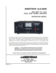
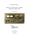
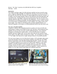
AMERITRON ARI-500
AUTOMATIC BAND SWITCH FOR THE ALS-500M/ALS-600 AMPLIFIERS
INSTRUCTION MANUAL
AMERITRON
116 WILLOW ROAD
STARKVILLE, MS 39759 USA
662-323-8211
ARI-500 Automatic Band Switch for ALS-500/600
Instruction Manual
Contents
Introduction............................................................................................................ 2
Features ................................................................................................................. 2
Specifications......................................................................................................... 2
Installation ............................................................................................................. 3
Operating ALS-500RC with the ARI-500 ............................................................ 3
ARI-500 Transceiver Compatibility …. ................................................................ 3
Interfacing ARI-500 to Radio for Keying and Band Data …. ............................... 4
Interfacing to Icom Radios ................................................................................... 4
Interfacing to Yaesu Radios ................................................................................. 5
Interfacing to the Elecraft K3 ............................................................................... 6
Interfacing to Kenwood Radios ........................................................................... 6
Operation ............................................................................................................. 8
Technical Assistance.............................................................................................. 9
Schematic............................................................................................................... 10
ARI-500 Transceiver Interface Cables................................................................... 13
Warranty ................................................................................................................ 13
Ameritron ARI-500
Introduction
Congratulations on choosing the Ameritron ARI-500 Automatic Band Switch for the Ameritron ALS-500M (Ser. No. 13049 and
higher) and ALS-600 (Ser. No. 14378 and higher) amplifiers. The ARI-500 is designed to automatically select the correct frequency
range on these amplifiers by reading the frequency information or band data from the transceiver. This automatic switch is compatible
with most ICOM, Yaesu, and Kenwood transceivers, and the Elecraft K3 transceiver. Some other radios may also be compatible.
Features
PWR:
LINK:
RADIO:
AMP A/B:
REMOTE A/B:
Standby/Operate
Green LED indicates the amplifier and transceiver are connected correctly
Red LED indicates information is being received from transceiver. Flashing red indicates information is NOT being received.
RJ-45 Jack for interfacing to the transceiver.
RJ-45 Jacks for interfacing to the ALS-500M or ALS-600 Amplifier
RJ-45 Jacks for use with the optional ALS-500RC Remote Control Head
Toggle switch
Specifications
Receives DC power through the ALS-500M/600 interface cables.
Dimensions 4.5” W x 1.5” H x 4.25 D
Weight
0.4 lbs
2
ARI-500 Automatic Band Switch for ALS-500/600
Instruction Manual
Installation
The ARI-500 connects to the REMOTE A/B jacks on the front of the amplifier. Two RJ-45 cables are supplied to connect jack A
and B from the ARI-500 to the REMOTE A/B jacks on the ALS-500M or ALS-600.
1.
2.
3.
4.
Place the ARI in a suitable location.
Ensure the amplifier power switch is OFF and the amplifier’s frequency select switch is in the REMOTE position.
Plug one of the patch cords into AMP A on the ARI-500. Route the other end to the amplifier and connect it to the REMOTE
A amplifier input.
Plug the other patch cord into AMP B on the ARI-500. Route the other end to the amplifier and connect it to the REMOTE B
amplifier input.
Operating ALS-500RC with the optional ARI-500
Skip this section and go to ARI-500 Transceiver Compatibility if the ALS-500RC is not used.
The optional ALS-500RC Remote Control Head can be used with the ARI-500. The ALS-500RC provides current metering (ALS500M) or RF power output metering (ALS-600), TX and O/L (Fault) indications of the amplifier, and O/L resetting of the amplifier
via the ALS-500RC ON/OFF switch by cycling power on the ALS-500M, or operating as a OPERATE/STANDBY switch with the
ALS-600.
To use the ALS-500RC Remote Control Head with the ARI-500:
1) Connect a RJ-45 patch cable to Remote port A of the ARI-500.
2) Connect the other end of this RJ-45 cable to port A of the ALS-500RC remote.
3) ALS-500RC Port B is not used in this application.
Note:
JMP 2 inside the ARI-500 must be set as described below when the ALS-500RC is used:
1) JMP 2 in the 1-2 position (Fig. A): Factory default. Must be strapped this way when the ALS-500RC is NOT used.
2) JMP 2 in the 2-3 position (Fig. B): Strapping position when using the ALS-500RC. The Current/RF Power Meter, Power,
TX and O/L indicators are all functional. The ARI-500 Auto O/L Reset (Fig. C) is automatically disabled. The ALS-500RC
POWER switch turns the ALS-500M power ON and OFF, and functions as the ALS-600 OPERATE/STANDBY switch.
Manually reset O/L on both amplifiers by switching the ALS-500RC’s POWER Switch OFF and then ON. When the ALS500RC POWER is switched ON, it takes about four seconds for the ALS-500 to turn on or the ALS-600 to reset.
JMP 2
FIGURE A
(Factory Default)
JMP 2
FIGURE B
Note: JMP 2 MUST be in the Factory Default position (FIGURE A) if the ALS-500RC Remote Control Head is NOT used.
Note: JMP 3 should be set to OFF (Figure C) when using the ALS-500RC, as the ALS-500RC provides manual reset functionality.
ARI-500 Transceiver Compatibility
The ARI-500 is compatible with most ICOM, Kenwood and Yaesu radios for reading band data information and detecting transmitter
keying. Additionally, the ARI-500 low drive current keying interface is compatible with virtually any transceiver’s amplifier keying
output. Newer Kenwood radios have a DB-9 male connector for computer control. Serial data is read from this port to get the band
data. ICOM Transceivers use a “step voltage” for band data. A voltage of 0-8 volts is output from the band data pin of the accessory
jack. Yaesu, older Kenwood, and Elecraft K3 radios output band data in a 4-line BCD format (the Unified Microsystems plan).
Many other transceivers use the 4-line BCD standard as well. Check your transceiver’s instruction manual to see if this is the case. If
so, it will also be compatible with the ARI-500.
3
ARI-500 Automatic Band Switch for ALS-500/600
Instruction Manual
Interfacing the ARI-500 to Radio for Keying and Band Data
The ARI-500 RADIO input connection is a RJ-45 jack with specific connections for each radio brand. The diagram below shows the
pin-out of the RADIO input jack. See the specific sections below for more information on interfacing to each particular radio brand.
Rear Panel View
12345678
1
Ground
2
Key In
3
Kenwood RX
4
Kenwood TX / Yaesu BCD D
5
Yaesu BCD C
6
Yaesu BCD B
7
Yaesu BCD A / Icom Power
8
Icom Band Data
NOTE: Multiple radios cannot be simultaneously connected to the
ARI-500. The ARI-500 is designed to operate with only
ONE radio.
Interfacing to ICOM Radios
In order to retrieve band data from ICOM radios, the ARI-500 must be connected to the band data voltage output. This can be found
on the ACC jack on the back of the radio. This 13- or 7-pin jack has the band data voltage, amp-key out (goes to ground when the
radio is transmitting), ALC input, and ground. The diagrams below show the connections required between ICOM radios and the ARI500. Connection to an ICOM IC-7000 requires an ICOM approved modification. Follow the instructions in your IC-7000 user’s
manual (page 140) to make the modification. Ameritron will not be held liable for any damage caused by this modification to an IC7000 transceiver. Also note the ALC connection on the IC-706/7000/718 as this is only available on the ICOM accessory connector.
ALC is available on a separate phono jack on the IC-746/756.
ICOM 706/718/7000*
ALC
Rear View of
ICOM radio
13
9 1 0 11 1 2
5 6 7 8
1 2 3 4
Rear View of
ARI-500
Gnd
13.8V
ARI-500
Amp Key
12345678
Band Data
Radio Input
*IC-7000 requires modification for ARI-500 operation
. See paragraph
above.
ICOM 746/756
13.8V
Band Data
ARI-500
Gnd
Rear View of
ICOM radio
4
1
6
2
5
3
7
Rear View of
ARI-500
Amp Key
12345678
Radio Input
Connection
Band Data Voltage
Icom Power (13.8V)
Amp Key / HSend
Ground
4
ARI-500 Radio Input
Pin 8
Pin 7
Pin 2
Pin 1
ARI-500 Automatic Band Switch for ALS-500/600
Instruction Manual
Interfacing to Yaesu Radios
Yaesu radios output band information using a 4-line BCD format. The band data lines are found on the BAND DATA connector or
LINEAR port on most Yaesu radios. Some Yaesu radios share the CAT port with the LINEAR port. The radio must be configured so
that the port is in LINEAR mode or the band data information will not be sent to the ARI-500. Check your radio’s manual to
determine the proper configuration of the LINEAR port. The diagrams below show popular Yaesu connections to the ARI-500.
Double check your radio’s manual to ensure the correct Band Data connections. Please note that Pin 8 on the Yaesu connector (TXINH) must be connected to ground, Pin 3 on the FT-MP/2000/9000 series of radios. This connection is optional on the FT857/897/100 radios.
Yaesu FT-857/897
ARI-500
Linear Port
Rear View of
Yaesu Transceiver
8
7
6
5
4
3
2
TX Gnd
BCD D
BCD C
Gnd
BCD B
1
Yaesu FT-100D
12345678
Rear View of
ARI-500
Radio Input
BCD A
ARI-500
Linear Port
BCD A
TX Gnd
Gnd
Rear View of
Yaesu Transceiver
1
Rear View of
ARI-500
2
3
4
5
6
7
8
BCD B
12345678
Radio Input
BCD D
BCD C
TX Gnd
BandA
BandB
BandC
2
4
5
1 2 3 4 5 6 7 8
GND
1
6
3
Linear
7
8
BandD
Connection
Band Data A
Band Data B
Band Data C
Band Data D
Amp Key / TX GND
Ground
Yaesu MP/2K/9K Cabling
ARI-500 Radio Input
Pin 7
Pin 6
Pin 5
Pin 4
Pin 2
Pin 1
Yaesu Linear Socket
Pin 4
Pin 5
Pin 6
Pin 7
Pin 2
Pin 3/8
5
ARI-500 Automatic Band Switch for ALS-500/600
Instruction Manual
The Yaesu FT-450/950 transceivers provide Band Data, ALC, and AMP Keying from a 10-pin MiniDIN connector on the back of
these radios. These connectors are very difficult to find, therefore it is best to purchase the Yaesu CT-118 Band Data cable (~ $40
from most suppliers), and then construct the cable below to interface from the CT-118 to the ARI-500.
Band A
Band B
Band C
Band D
TX GND
1
2
9
3
4
10
5
11
12
6
13
7
8
14
15
1 2 3 4 5 6 7 8
GND
DB15-S
Solder-cup View
FT-450/950
Radio Input
(Intfc to CT-118)
Interfacing to the Elecraft K3 Transceiver
The Elecraft K3 outputs band information using the standard 4-line BCD format. Since about SN2370, all K3 radios have pull-up
resistors on the K3 Band Data lines (required). Check the K3 modification page at www.elecraft.com for the modification for earlier
K3 radios.
AMP KEY OUT
GND
K3 Accessory Connector
5
4
10
15
3
2
9
14
8
13
1
7
12
1 2 3 4 5 6 7 8
Band1
6
Band2
11
HD15-S
Solder-cup View
Band0
Band3
K3 Interface
Connection
ARI-500 Radio Input
Band Data A
Band Data B
Band Data C
Band Data D
Amp Key / TX GND
Ground
Pin 7
Pin 6
Pin 5
Pin 4
Pin 2
Pin 1
K3 Accessory
Socket
Pin 13
Pin 3
Pin 9
Pin 14
Pin 10
Pin 5
Interfacing to Kenwood Radios
The Computer port (CAT) is used to retrieve the frequency of the radio. When the ARI-500 is first turned on, the “Auto Information”
(AI) command is sent to the radio. This command causes the Kenwood radio to output the state of the radio (frequency, mode, etc)
anytime the state has changes. The ARI-500 then uses the frequency to determine the appropriate band and then selects the correct
antenna. The diagram below shows how to connect a Kenwood radio with a DB-9M COM port to the ARI-500. Note that pins 7 and
8 (RTS, CTS) on the Kenwood port must be connected together. This ensures that the Kenwood will send the status information to
the ARI-500. There is one second delay from when the status of the radio changes until it is sent out over the serial connection. The
Remote port on the back of Kenwood radios has the amp-key line needed for the ARI-500, and the ALC input from the amplifier if
you wish to use it. Refer to the Kenwood manuals and turn on the amplifier keying relay and set the BAUD rate to 9600.
6
ARI-500 Automatic Band Switch for ALS-500/600
Instruction Manual
Kenwood TS-570, TS-870, TS-2000,
(*TS-480 see Addendum in rear of this manual)
Com Port
9 8 7 6
5 43 2 1
ARI-500
TXD
Amp Key
RXD
Rear View of
Kenwood Transceiver
4
Rear View of
ARI-500
Gnd
2
5
1 Remote 3
6
12345678
7
Radio Input
ALC
ARI-500 (Radio Input) RJ-45 Connector Wiring
Pin 1 Ground connects to pin 1 of Radio Com port and pin 2 of Radio Remote Connector
.
Pin 2 Amp key connects to pin 4 of Radio Remote Port.
Pin 3 (RXD ) connects to pin2 of RadioCom Port
Pin 4 (TXD) connects to pin 3 of Radio Com Port.
Pin 5 not connected.
Pin 6 not connected.
Pin 7 not connected.
Pin 8 not connected.
Pin 9 n ot connected.
Note: Pins 7 and 8 on the Kenwood Com Port must be connected
together. This ensures the radio will send information to the ARI-500.
* The Kenwood TS-480 requires different connections. See the Addendum
in the rear of this manual.
Kenwood TS570/870/2000 Interface to ARI-500
Connection
Kenwood Com Port
Kenwood RXD
ARI-500 Radio
Input
Pin 3
Kenwood TXD
Pin 4
Pin 3
N/C
Amp Key
Pin 2
N/C
Pin 4
Ground
Pin 1
Pin 5
Pin 2
ALC
N/C
N/C
Pin 6
Pin 2
Kenwood Remote
Port
N/C
Note: Pins 7/8 on the Kenwood Com Port must be connected together.
Interfacing to the Kenwood TS-480 Radio
The pin number connections are the same as for the TS-2000/570/870, but the TS-480 uses an 8-pin MiniDIN connector on the
Remote Port. Pins 7 & 8 on the Kenwood Com Port MUST be connected together.
12345678
Kenwood Com Port
Kenwood Remote Port
Connection
ARI-500 Radio Jack
Kenwood TS-480 Interface to ARI-500
Kenwood Com Port
Kenwood RXD
ARI-500 Radio
Input
Pin 3
Pin 2
Kenwood Remote
Port
N/C
Kenwood TXD
Pin 4
Pin 3
N/C
Amp Key
Pin 2
N/C
Pin 4
Ground
Pin 1
Pin 5
Pin 2 & Shield
ALC
N/C
N/C
Pin 6
7
ARI-500 Automatic Band Switch for ALS-500/600
Instruction Manual
The ARI-500 receives band information over the serial interface, while amplifier keying comes from the remote port. The serial
communications settings are 9600 bps and the linear amplifier relay must be turned on and must be setup on the radio for the ARI-500
to function properly. The serial communications setting is Menu 56 and needs to be set to 9600. The amplifier relay setting is Menu
28 and should be set to option ‘2’.
Operation
Set the amplifier’s Frequency Select Switch to the REMOTE position. The amplifier frequency band will now be controlled by the
transceiver through the ARI-500. The amplifier will also now be keyed through the ARI-500. The relay jack on the back of the
amplifier is not used. The green PWR LED and the red LINK LED will glow steadily when the ARI-500 amplifier interface cables
are connected properly and data is being received from the transceiver. If the transceiver is off or data is not being sent, the PWR
LED will flash on for about one second when amplifier power is turned on, and the LINK LED will flash continuously
Toggle Switch: This switch in the down position will place the amplifier into standby. Up position will place amplifier into
operate. Note: This switch must be in the down position when powering up the ALS-1300 to prevent a load fault command.
Note: The ALS-600 will be placed in OPERATE whenever keying is applied through the ARI-500 regardless of the STANDBYOPERATE switch position on the amplifier. If the ALS-500RC Remote Control Head is used, the ALS-600 may be taken off
line with the ALS-500RC POWER switch (ARI-500 JMP2 must be strapped 2-3, FIGURE B, when the ALS-500RC is used).
Note: JMP 2 MUST be in the Factory Default position (FIGURE A) if the ALS-500RC Remote Control Head is NOT used.
The ALS-500M/600 Power On/Off switch operates the same as without the ARI-500M. If the Remote ALS-500RC is used, refer to
Operating the ALS-500RC with the ARI-500.
The ARI-500 has an Auto Reset for the amplifier’s load fault (O/L). When the amplifier goes into load fault mode, the ARI-500 will
wait 5 seconds and then reset the amplifier’s LOAD FAULT circuitry by cycling the ALS-500M amplifier’s power OFF and back ON
(the ALS-500M amplifier’s power switch must be in the OFF position for the Auto Load Fault reset to work), or by remotely cycling
the ALS-600 OPERATE/STANDBY function. The ARI-500 will reset the amplifier overload up to 3 times in a 5-minute period. If
the amplifier load faults more than 3 times in a 5 minute period, the amplifier’s power must be manually switched off to reset. Strap
JMP3 to OFF to disable the Auto Reset feature (see Figure C).
Note: If Auto Reset is disabled, power must be manually cycled on both the ALS-500M and ALS-600 to re-set the load fault circuitry
(or cycle the POWER switch on the ALS-500RC if used).
Note: When the ALS-500RC is used with the ARI-500, the ARI-500 Auto Reset feature is automatically disabled. Manual reset is
performed with the ALS-500RC POWER switch. Strap JMP3 to OFF (Figure C).
22.5 to 30 MHz (10/12 Meter) Operation
The ARI-500 has a jumper labeled JMP1. JMP1 is for operation on frequencies between 22.5 and 30 MHz (AUX). The factory
default is in the OFF position. The OFF position prevents the amplifier from operating when the transceiver is in the 10/12 Meter
band. Move JMP1 to ON if the amplifier has the 12/10 Meter kit installed. See Fig C.
ON
OFF
JMP 1 (12/10 Meter Enable)
JMP 3 (Auto LOAD FAULT re-set)
FIGURE C
The PWR and Link indicator lights illuminate steadily when the transceiver and amplifier are connected and turned on. The red LED
marked LINK will blink rapidly if the ARI-500 RADIO jack is not receiving information from the transceiver.
Note About Kenwood Radios
Since the Radio Control Port is used to get the band information from the radio, the radio must be switched on first
before powering up the ARI-500. Upon power up, the ARI-500 sends the Auto Information (AI) command to the
Kenwood radio. This instructs the Kenwood to send the radio’s status information anytime it changes. Failure to do this
will result in the radio not receiving this command and the ARI-500 not detecting a properly connected radio. Anytime
the status of the radio changes, there is a one second delay before the new information is sent over the serial line to the
ARI-500. This causes the switch to appear to respond slowly to the band changes. This is a result of the delay from the
8
Kenwood
radio, NOT the ARI-500. Note: Kenwood Com Port pins 7 & 8 must be connected together.
ARI-500 Automatic Band Switch for ALS-500/600
Instruction Manual
Technical Assistance
If you have any problem with this unit, first check the appropriate section of this manual. If the manual does not reference your
problem or reading the manual does not solve your problem, call Ameritron at 662-323-8211. We can only help if you have your
ARI-500 manual, radio manual, and information about your station available during the call.
We strongly recommend calling Ameritron with any questions, but questions can also be mailed directly to Ameritron at 116 Willow
Road, Starkville, MS 39759 or Faxed to 662-323-9810. Please be aware that MFJ is a separate facility, and as such does not always
offer the best assistance with Ameritron products. Be sure to send a complete description of the problem, explain how this unit is
being used, and include a complete description of your station.
NOTES:
9
ARI-500 Automatic Band Switch for ALS-500/600
Schematic
10
Instruction Manual
ARI-500 Automatic Band Switch for ALS-500/600
Instruction Manual
11
ARI-500 Automatic Band Switch for ALS-500/600
12
Instruction Manual
ARI-500 Automatic Band Switch for ALS-500/600
Instruction Manual
ARI-500 TRANSCEIVER INTERFACE CABLES
•
•
•
•
•
RJ-DB97DK for Kenwood
RJ-13D for the ICOM IC-706/718 and IC-7000
RJ-7DI for all other Icoms
RJ-8D for Yaesu
Check with Ameritron for cable details additional cables as they become available
DISCLAIMER
Information in this manual is designed for user purposes only and is not intended to supersede information contained in customer
regulations, technical manuals/documents, positional handbooks, or other official publications. The copy of this manual provided to
the customer will not be updated to reflect current data.
Customers using this manual should report errors or omissions, recommendations for improvements, or other comments to Ameritron
116 Willow Road, Starkville, MS 39759. Phone: (662) 323-8211; FAX: (662) 323-6551. Business hours: M-F 8-4:30 CST.
AMERITRON
116 Willow Road
Starkville, MS 39759 USA
662-323-8211
LIMITED WARRANTY
Ameritron warrants to the original purchaser that this product shall be free from defects in material or workmanship for one year from the date of
original purchase.
During the warranty period, Ameritron (or an authorized Ameritron service facility) will provide free of charge both parts and labor necessary to
correct defects in material or workmanship.
To obtain such warranty service, the original purchaser must:
(1)
Complete and send in the Warranty Registration Card.
(2)
Notify Ameritron or its nearest authorized service facility, as soon as possible after discovery of a possible defect, of:
(a) the model number and serial number, if any:
(b) the identity of the seller and the approximate date ofpurchase;
(c) a detailed description of the problem, including details on the equipment.
(3) Deliver the product to the Ameritron or the nearest authorized service facility, or ship the same in its original container or equivalent, fully
insured and with shipping charges prepaid.
Correct maintenance, repair, and use are important to obtain proper performance from this product. Therefore, carefully read the Instruction Manual.
This warranty does not apply to any defect that Ameritron determines is due to:
(1) Improper maintenance or repair, including the installation of parts or accessories that do not conform to the quality and specifications of the
original parts.
(2) Misuse, abuse, neglect or improper installation.
(3) Accidental or intentional damage.
All implied warranties, if any, terminate one (1) year from the date of the original purchase.
The foregoing constitutes Ameritron's entire obligation with respect to this product, and the original purchaser and any user or owner shall have no
remedy and no claim for incidental or consequential damages. Some states do not allow limitations on how long an implied warranty lasts or do not
allow the exclusion or limitation of incidental or consequential damage, so the above limitation and exclusion may not apply to you.
This warranty gives specific legal rights and you may also have other rights, which vary from state to state.
13