1
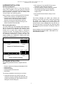
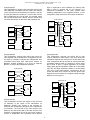
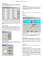
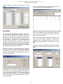
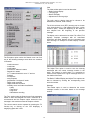
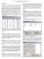
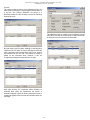
Data Device Corporation, 105 Wilbur Place, Bohemia, NY 11716
1-800-DDC-5757 | 631-567-5600
'DWD'HYLFH&RUSRUDWLRQ
NHI-15515
1553 PCI/S IDEA Card
USER’S MANUAL
May 2005
This material is the property of ''& and is
furnished solely to aid in the installation, operation and
maintenance of NHI products. The information contained in
this document is proprietary to ''& and may not be used,
duplicated or disclosed in any shape or form for any reason
other than the intended purpose without prior written consent
of National Hybrid, Inc.
Data Device Corporation, 105 Wilbur Place, Bohemia, NY 11716
1-800-DDC-5757 | 631-567-5600
INTRODUCTION
The 1553-IDEA PCI/S is a Plug&Play PCI bus compatible
card that functions as a tester/simulator for MIL-STD-1553
systems. The card’s architecture is based on an enhanced
version of the popular IDEA MK III board and is divided
into two identical halves which operate concurrently. Each
half emulates a Bus Controller with up to 31 independent
Remote Terminals, or a Bus Monitor.
The Bus Controller supports up to 1000 independent
messages and data tables. The messages are organized
in a frame which holds up to 1000 entries; both major and
minor frame periodicities are supported and timing is
accurate to within 4 microseconds.
The Remote Terminals support up to 1022 data tables
which are accessed as a function of the command's
terminal address, T/R bit and subaddress. Each of the 31
Remote Terminals has its own unique status which is
dynamically updated as required by MIL-STD-1553.
Protocol options such as broadcast, legality detection and
dynamic bus control are supported. In addition, each
Remote Terminal has its own error injection definition and
can be used to thoroughly test external Bus Controllers.
The intelligent Bus Monitor is triggered by error type,
command type, bits set in status words or an external TTL
input. Messages are selected according to the command
fields: terminal address, T/R bit and subaddress as well as
the bus ID. The Monitor detects and reports all errors
defined by MIL-STD-1553B and supports sustained realtime storage to disk of messages from a fully loaded bus.
The card has outstanding error injection capability and
provides all the errors defined by the SAE Validation Test
Plan for Remote Terminals. These capabilities include:
encoding errors such as sync/parity/half-bit inversion,
length errors (words per message and bits per word), gap
errors, zero-crossing errors, and response errors. A unique
feature of the card is the ability to inject glitches to
simulate the most common source of errors encountered
during a noise test.
Each half of the card contains a dual redundant
transceiver which can be shared by both halves or
operated
independently.
The
transmitters
have
programmable rise times ranging from less than 100
nanoseconds to more than 250 nanoseconds and their
amplitude can be varied from 0 to over 28 Vpp across 75
ohms.
The card has 2 connectors on its rear bracket. The first
connector is a standard female 9 pin D-type that contains
four 1553 transformer coupled stub signals. A mating
connector is supplied which brings out these signals to 4
short pigtails with twinax jacks that can be mated with
industry standard PL-75 plug connectors.
The second connector is a female 25 pin D-type that can
be used for general purpose I/O.
Features
• Simulation and test of MIL-STD-1553
systems
•
Plug&Play PCI target
•
Simultaneous emulation of BC, 31 RTs,
and Monitor
•
Industry's most complete error injection
and detection capability
•
512K Bytes of shared RAM
•
Selective message Monitor
•
32-bit time tag
•
User-friendly Windows 95/98/2000/NT/XP
Menu Software and Runtime Libraries
•
Two dual redundant channels with four
transceiver connection options
User-friendly menus for interactive operation as well as an
extensive run-time library (RTL) for customer developed
applications are supplied with the card. These packages
run under Windows 95/98/NT/2000/XP.
The RTL contains over 100 functions written in Microsoft
C/C++ and complies with VISA software conventions to
facilitate platform portability. The library is compatible with
Visual Basic 4 and 5. Support is provided for doublebuffered data tables and message frames, queued
interrupts, block data transfers via 1553, and over 30
special routines executed by the board's BC/RT during
intermessage gaps. Data structures can be created, tested
and saved using the menu software and then imported by
the library. The run-time library is therefore an ideal tool for
highly efficient sophisticated real-time applications.
Two very useful software packages are included without
additional cost. The first program is a powerful Parameter
Monitor for real-time or off-line analysis and display of data
in graphical form. The second program is a
Communication Reconstructor which facilitates system
integration by replaying previously monitored messages
with the original contents and timing.
1
Data Device Corporation, 105 Wilbur Place, Bohemia, NY 11716
1-800-DDC-5757 | 631-567-5600
2) Run "setup.exe" from the IDEA CD and, upon
completion, power-down the computer.
3) Turn the computer on again. When the computer
has finished rebooting, the "New Hardware
Found" Dialog box will reappear. Select the
ideapci.inf file.
HARDWARE INSTALLATION
Hardware Configuration
The 1553-IDEA PCI/S Card is a true Plug and Play
device. When installed in one of the PC's PCI slots and
rebooted, the board is automatically detected and reports
stored parameter information such as memory and
interrupt usage to the operating system.
4) Run the IDEA Control Panel to assign a card
number.
When installing a card, the following should be observed:
• Never insert or remove a card with the power on
• Insert the card so that the two D-type connectors
protrude from the rear opening and then gently
press the card into the mother-board connector
• Make sure that adjacent cabling and wiring do not
hinder the airflow around the card
The Device Manager list should now indicate the
presence of the board. This can be verified by accessing
the System icon located in the Control Panel and
selecting the Device Manager tab. Scroll through the list
until the device is seen. Highlight this entry and click on
the Properties button. This will open the properties dialog
box and show general information including the status of
the board.
Bus Coupling Alternatives
The card contains two dual redundant 1553 transceivers
that can be connected to separate MIL-STD-1553 buses
that are referred to as Channel1 and Channel2. Each
channel can be either direct coupled or transformer
coupled to the card. The coupling mode for Channel1 is
determined by jumpers JP5-JP8 and the coupling mode
for Channel2 is determined by jumpers JP1-JP4. The
jumper positions for Transformer coupling and Direct
coupling are illustrated below.
JP8 - AN
JP7 - A
JP6 - B
JP5 - BN
CHANNEL1
JP3 - B
JP1 - BN
JP4 - AN
JP2 - A
On the desktop you can now select Start -> Programs ->
IDEA Windows for Windows 2000 -> IDEA Menu to run
the IDEA Menu program.
CHANNEL2
Jumpers for Transformer Coupling
JP8 - AN
JP7 - A
JP6 - B
JP5 - BN
CHANNEL1
JP3 - B
JP1 - BN
JP4 - AN
JP2 - A
CHANNEL2
Jumpers for Direct Coupling
SOFTWARE INSTALLATION
The following standard software is supplied with the
board:
•
•
•
•
•
Runtime Libraries for Windows 95/98/2000/ NT/XP
Windows Menu
Parameter Monitor
Communications Reconstructor
Stack Editor
The software installation instructions are as follows:
1)
Install the board into one of the PCI slots and
restart the computer. Windows will detect the new
hardware and display the "New Hardware Found"
Dialog box. Exit the dialog box.
2
Data Device Corporation, 105 Wilbur Place, Bohemia, NY 11716
1-800-DDC-5757 | 631-567-5600
Menu software supports modification of data during RUN
mode.
IDEA MENU
The IDEA Menu application allows full control over the
IDEA-1553 PCI/S board without having to write a single
line of code. This is accomplished through a user-friendly
intuitive graphical interface.
STACK mode is used to display and analyze monitored
1553 messages. Since the stack can be of considerable
size (the maximum capacity is only limited by free disk
space), tools are provided for searching, selecting,
saving, and printing the stack.
SETUP MODE
Selecting and Opening Files
The setup menu is used to select setup and stack files as
well as to open setups so that they can be modified.
Selecting Card, Stack Size, and Count Display
The setup menu can also be used to select the card
number when more than one IDEA card is resident in the
computer and to limit the stack file capacity to any
desired size. In addition, the display of counters, which
are updated by the Monitor during message reception,
can be toggled on/off by clicking the View Counts option.
Special PCI Mode
Since the 1553-IDEA PCI/S card has 2 functionally
independent halves and 4 possible transceiver
connections, the Special PCI Mode menu is provided to
define the card's configuration.
Setup, Stack and Project Files
If you are using the IDEA Menu for the first time, select
New under the IDEA Menu File option. This will create a
default setup file (idea.stp) and a default stack file
(example.stk). Setup files contain all the parameters, data
and messages used by the card. Stack files are used to
store messages received by the card's Monitor. The
setup and stack file names can be modified later and new
files added by selecting the New option as desired.
The function of each half of the card is determined by
checking the BC, RT or Monitor boxes. If BC is selected,
then all enabled RTs will also be activated. However, if
RT is selected, only RTs will be enabled.
When Save is chosen under the File option, the names of
the current setup and stack files, together with the
associated card number and special PCI configuration
parameters can be stored in an IDEA project file (*.ire).
Project files are used to recreate the environment that
existed when they were last saved and provide a
convenient method for keeping track of setups when
more than one IDEA card is used in the same computer
(up to 8 IDEA cards can be mounted in the same
computer). Existing project files can be opened by
clicking on Open under the File option.
IDEA MENU MODES OF OPERATION
The Menu has 3 modes of operation: Setup, Run and
Stack.
SETUP mode is used to define all the parameters,
messages and data used by the card. The setups can be
saved in files and loaded later as desired.
The card supports 4 types of transceiver connections to
Channel1 and Channel2. The configurations and their
corresponding simplified block diagrams are described
below.
RUN mode is used to execute 1553 communication: the
BC/RTs transmit and receive bus traffic and the Monitor
stores the messages in a cyclic buffer. The PC, in realtime, copies the Monitor's buffer to a much larger stack in
its own memory space and updates a screen of counters
(number of messages and error types per RT). The IDEA
3
Data Device Corporation, 105 Wilbur Place, Bohemia, NY 11716
1-800-DDC-5757 | 631-567-5600
Configuration #1
This configuration is similar to the connection used by the
older IDEA MK II and MK III ISA bus cards. The first half
of the card receives and transmits on Channel 1 and the
second half shares the Channel 1 receiver with the first
half. Configuration #1 can be used, for example, when
the first half functions as a BC/RT and the second half
functions as a Monitor on the same dual redundant bus.
logic is employed to avoid oscillation by ensuring that
when a word is received first on one channel, it is
transmitted immediately to the other channel while
inhibiting transmission in the opposite direction. In this
configuration, both card halves can function as Monitors.
CARD HALF #1
RXA
Decoder
A
TXA
CARD HALF #1
1553
XCVR
RXA
Decoder
CH1
RXB
B
Encoder
A
TXB
TXA
1553
XCVR
CH1
RXB
B
Encoder
TXB
RXA
Decoder
A
TXA
1553
XCVR
RXA
Decoder
A
TXA
1553
XCVR
CH2
RXB
B
Encoder
TXB
CH2
RXB
B
Encoder
CARD HALF #2
TXB
CARD HALF #2
Configuration #4
This configuration connects the logical OR of both
receiver channels to both halves of the card, while both
transmitter channels are connected to the first half of the
card. Configuration #4 can be used to communicate with
2 separate channels when it is desired to use the same
BC for both of them. A typical application is pre-flight
testing when ground equipment resides on a terminated
1553 bus and flight equipment resides on a terminated
1553 bus in the flight platform. Configuration #4 will
enable the IDEA BC to connect to both the ground and
flight buses and treat them as a single bus when the flight
platform is on the ground.
Configuration #2
This configuration connects each half of the card to its
own separate dual redundant bus. Configuration #2 can
be used, for example, to Monitor two independent dual
redundant buses when both card halves function as
Monitors. Another possibility is to serve as separate
BC/RTs on each of the independent channels.
CARD HALF #1
RXA
Decoder
A
TXA
1553
XCVR
CH1
RXB
B
Encoder
TXB
CARD HALF #1
RXA
Decoder
A
TXA
RXA
Decoder
1553
XCVR
A
TXA
1553
XCVR
CH1
RXB
CH2
Encoder
B
TXB
RXB
B
Encoder
TXB
CARD HALF #2
RXA
Decoder
A
TXA
Configuration #3
This configuration connects the outputs of the receivers
on Channel1 to the inputs of the transmitters on
Channel2. Similarly, the outputs of the receivers on
Channel2 are connected to the inputs of the transmitters
on Channel1. The first half of the card receives from
Channel1 and the second half of the card receives from
Channel2. Configuration #3 can be used as a bridge to
connect 2 independent dual redundant buses. Special
1553
XCVR
CH2
RXB
Encoder
TXB
CARD HALF #2
4
B
Data Device Corporation, 105 Wilbur Place, Bohemia, NY 11716
1-800-DDC-5757 | 631-567-5600
Editing the Setup
After a setup file is opened, the Setup Editor is invoked
and the following screen is displayed:
Status Mask
The Monitor masks all the status words on the 1553 bus,
and, if a bit in the mask word is set to 1 and the
corresponding bit in the status is also set to 1, the
Monitor will detect an exceptional condition. Exceptional
conditions are counted in real-time and denoted in the
stack. The BC also has access to the status mask and its
operation can be modified when an exceptional status
condition is detected.
The most significant 5 bits in the STATUS MASK are
always 0's; the remaining bits are defined by the user.
The Setup Editor is an independent application that can
be activated either from the main IDEA menu or by
clicking the Setup Editor icon. The File option is used to
load and save setup files. The Global Definitions options
are used to define parameters that affect more than one
of the basic functions: Bus Controller, Remote Terminal
and Monitor. The BC option is used to define messages
and their frames (sequences of messages) to be issued
by the Bus Controller. The RT option is used to define the
simulated RTs parameters and to associate data tables
to receive/transmit commands. The Monitor option is
used to select the types of messages to be monitored
and the criterion for initiating message storage.
Global Definitions
The options under this menu are: Legality, Status Mask,
Terminal Activity, Response Timeout, Transmit Amplitude
and Expanded Mode.
Legality
The Legality menu is used to define whether or not mode
command legality detection is activated for the simulated
RTs, whether or not broadcast commands are legal and
which mode commands are to be considered legal/illegal.
The legality definition is common to both the receive and
transmit versions of the mode command. Checking a
mode command defines it as legal. In addition, two
intermessage routines can be associated with each mode
command (please refer to the BC for details).
5
Data Device Corporation, 105 Wilbur Place, Bohemia, NY 11716
1-800-DDC-5757 | 631-567-5600
Terminal Activity
The Terminal Activity menu is used to define which
terminal addresses are to be simulated by the IDEA card
and to assign names to them.
Expanded Mode
When Expanded mode is checked, the card and software
support up to 1000 independent messages and up to
1022 independent data tables. This mode is unique to
the IDEA PCI card.
BC
The Bus Controller has two main menus: Message and
Frame.
Message
The message menu is shown below.
A terminal address can also be assigned to the Bus
Controller since it may pass control to another RT and
become an RT itself. Dynamic bus control acceptance by
an RT is supported (please refer to the RT menu for more
details).
Response Timeout
The response timeout menu is used to define the BC's
timeout when waiting for a status response. The same
value is used by the Monitor to flag no responses in the
message stack. The timeout can range from 14 to 128
microseconds and has a resolution of 2 microseconds.
Message Name
Each of the 1000 messages can be assigned a name.
For convenience, the default names are MSG_1,
MSG_2…. and they can be modified if desired.
Message Type
The five types of messages: Receive, Transmit, RT-RT,
Mode Receive and Mode Transmit are selected by
successive clicks on the TYPE box. The arrow in the
TYPE box indicates the direction of the data
transmission: from the BC to the RT or from the RT to the
BC.
Transmit Amplitude
The transmit amplitude of the BC and RT can be varied
between 0 to at least 28 Vpp by entering a number
between 0 and 255.
Message Bus
The 1553 bus (A or B) is selected by clicking on the bus
symbol.
Message Command and Data
The window to the left of the TYPE box shows
information relevant to the BC (except for RT-RT
messages): the command value in hexadecimal and the
data table used by the BC. When the window is clicked, a
menu appears which can be used to specify the data
table and its contents. The table is selected by scrolling
down and clicking on the desired table name. Its contents
can then be modified by clicking on Data Table and
editing the displayed table.
6
Data Device Corporation, 105 Wilbur Place, Bohemia, NY 11716
1-800-DDC-5757 | 631-567-5600
The next field in the Message menu defines the time to
the next message. This value includes the time needed to
execute the message plus the gap until the next
message. The default value for the intermessage gap is
approximately 25 microseconds. For example, if the
message is of type Receive and the word count is 8
words, then the default value will be: (1 command word +
8 data words + 1 status word)*20 + 10 microseconds
status response time + 25 microseconds intermessage
gap = 235 microseconds. In most cases, the default value
of the time is the minimum that can be achieved. The
message time can be modified by clicking User and
entering the desired value. Message timing is accurate to
within approximately 2 microseconds.
The window to the right of the TYPE box shows
information relevant to the RT, and when it is clicked, a
menu appears which can be used to specify the terminal
address, subaddress and word count fields in the
command.
Message Routines
The InterMessage Routine menu provides a unique and
very useful feature. By clicking on the window, two
routines can be selected from a list of functions to be
executed by the BC before the next message. The
following table lists the routines relevant to the BC.
INTERMESSAGE ROUTINES for BC
When RT-RT is
right windows
transmitting and
they are clicked,
be edited.
No Operation
Retry Current Message On Alternate Bus
Retry Current Message and Remain on Alternate Bus
Retry on Same BUS
Interrupt on End of Message
Interrupt on Frame Symbol
Retry on Same BUS and Then on Alternate Bus
Set Output Trigger
Reset Output Trigger
Wait for Input Trigger
Skip Next Message
selected in the TYPE box, the left and
show information relevant to the
receiving RTs respectively, and when
the information relevant to the RTs can
When the BC is external and only RTs are emulated by
the card, intermessage routines can still be executed. In
this case, they are associated to the data tables
accessed by the RT in response to the 1553 command
(please refer to the section on RT definitions).
When MODE is selected in the TYPE box and the right
window is clicked, the following menu is displayed. The
terminal address, subaddress and mode code can then
be edited.
Message Timing
7
Data Device Corporation, 105 Wilbur Place, Bohemia, NY 11716
1-800-DDC-5757 | 631-567-5600
BC Error Injection
When the Error box is checked, the following error menu
opens:
To create a Manchester encoding error in the second bit
of the terminal address in a command word, the following
values should be programmed:
There are three types of errors that can be injected by the
BC: length errors, gap errors and encoding errors.
Gap error of 1, 2, or 3 microseconds can also be inserted
before any data word.
Length errors consist of both word count and bit count
errors. Bit count errors of +3 to -3 bits can be injected into
any word and word count errors of -32 to +1 words can
change the actual number of data words sent by the BC
relative to the word count in the command. For example,
if the command specifies 7 data words and the word
count error is defined as -2, then only 5 words will be
sent. The first word in the message (i.e., the command) is
numbered 0 and the first data word is numbered 1.
Frame
The Frame, illustrated below, defines the contents and
timing for a complete communication period.
Two modifying functions, glitch and inverse, are used to
implement Manchester encoding errors. "Inverse"
complements the encoder output for a specified period of
time. "Glitch" forces an idle bus condition on the output of
the encoder for a specified length of time.
The encoding error timing is controlled by 2 parameters:
error location and error width. The error location is in turn
specified by defining the word number and the delay from
the start of the word in 50 nanosecond increments. The
error width is also defined in 50 nanosecond increments
up to a maximum of 3 microseconds.
For example, to program an inverted sync in data word 3,
the following values should be programmed:
The frame contains up to 1000 messages and is divided
into minor frames of equal duration. The minor frame time
has an accuracy of 5 microseconds and a maximum
32
value of 2 microseconds (over 1 hour). After the last
message in a minor frame is completed, the next
message will begin only after the minor frame time has
expired. This timing mechanism ensures that messages
will be issued with fixed periodicity which is independent
of message lengths and response times.
Each location in the Frame can be either a message
name or a special symbol (M for end of Minor or F for end
of the entire Frame). The values may be selected by
scrolling down the list of names/symbols .
8
Data Device Corporation, 105 Wilbur Place, Bohemia, NY 11716
1-800-DDC-5757 | 631-567-5600
In order to facilitate the editing of large frames, Insert and
Delete buttons are provided. Clicking Insert will cause the
currently selected name/symbol to be duplicated and all
subsequent names/symbols will be shifted down. Clicking
Delete will cause the currently selected name/symbol to
be deleted and all subsequent names/symbols will be
shifted up. In addition, the parameters of the currently
selected message are displayed at the top of the Frame
window and the message can be edited by clicking the
Edit button.
RT
The Remote Terminal menu is illustrated below:
The table assignment does not have to be unique: the
same table can be used by more than one RT and/or
several transmit/receive, subaddress values.
Two data tables have special names: Illegal Rx and
Illegal_Tx. When these names are assigned to a
particular
combination
of
transmit/receive
and
subaddress bits, the RT will consider the combination as
illegal. If a command is sent to the RT with an illegal
value, the RT will respond with the Message Error bit set
in its status.
RT Error Injection
When the Error box is checked, the following Error menu
opens:
RT Name and Terminal Address
Each of the 31 RTs can be assigned a name and a
corresponding terminal address. For convenience, the
default names are RT_0, RT_1…. and the corresponding
terminal addresses are 0, 1… The names and addresses
can be modified if desired.
RT Default Status
Each RT has its own default status word that is logically
OR'ed with the status sent over the 1553 bus. Bits are set
by checking the box adjacent to the bit name. In order to
provide accurate simulation of real 1553 systems, the
Message Error, Broadcast Command Received and
Dynamic Bus Control Acceptance bits are determined
dynamically as defined by MIL-STD-1553B.
RT Data Tables
Data Tables are assigned to each RT by assigning Data
Table names to the transmit/receive and subaddress bits
in the commands issued by the BC when communicating
with the RT. The assignment is performed by means of
the Data Table Assignment window.
Errors are defined individually for each RT (and not on a
per message basis as in the case of the BC). All error
types can be injected when the BC is external; however,
9
Data Device Corporation, 105 Wilbur Place, Bohemia, NY 11716
1-800-DDC-5757 | 631-567-5600
if a message is internal (i.e., both the BC and the RT are
emulated by the same card), then the only RT error type
executed is late response - other types will be ignored.
Late responses to internal messages are provided so that
external RTs participating in RT-RT transfers can be
tested.
The Monitor has two main options: Selection and
Capture.
Selection
The Selection menu specifies which messages should be
stored in the card's circular buffer and transferred to the
PC in real-time. The selection is based on the values of
the 11 bits: terminal address, T/R, subaddress, as well as
the desired 1553 bus.
The RTs ability to inject length, gap and encoding errors
is similar to the BC's capability (please refer to the
section dealing with BC error injection).
The RT can also inject response errors and illegal
terminal address errors. No response errors can be
defined for bus A, bus B or both bus A and B. Late
response errors can be specified from 14 to 30
microseconds with 1 microsecond resolution. Alternate
bus errors will cause the RT to respond on bus B when
receiving commands on bus A or on bus A when
receiving commands on bus B. Illegal terminal address
errors are defined by clicking the Illegal Tadr button and
specifying an address which is different from that
assigned to the RT. This will cause the RT to respond
with the wrong terminal address in its status word.
RT Dynamic Bus Control Acceptance
If "Yes" is selected for the Accept Bus Control option, the
RT will commence communication as a BC after the
specified delay. The delay can range from 40 to 130,000
microseconds.
The rows in the matrix correspond to terminal addresses
and the columns correspond to subaddresses. The matrix
values can be modified by double clicking the desired
terminal address/subaddress combination and clicking
one of the boxes on the right side of the window or typing
one of the following values:
RT Intermessage Routines
When an external BC is used, the RTs can also execute
two intermessage routines at the completion of a
message. The routines are determined by the data table
accessed by the RT during the message (please refer to
the section on Data Tables for details).
•
•
•
•
MONITOR
The Monitor operation is organized as a pipeline with 3
stages: the first stage monitors all messages received
from the bus, the second stage stores selected
messages in a circular buffer which resides in the card's
shared RAM, and the third stage transfers the contents of
the circular buffer to the PC memory and disk. The
second and third stages are programmed by the
SELECTION and CAPTURE menus respectively.
"R" - receive only
"T" - transmit only
"X" - both receive and transmit
"." - not selected (You can also enter a "space";
however, for readability, a period is echoed to the
screen).
Since the selection matrix contains 2048 entries, tools
are provided to facilitate the definition of its contents. If
the "All" button in the upper left corner is checked, then
all the matrix entries will be filled with the same value
when one of the buttons is clicked on the right side of the
window. If the button at the beginning of a row or at the
top of a column is checked, then only that row or column
will be filled.
The first stage of the Monitor's pipeline listens on both
buses until it detects a command and then receives
exclusively from the active bus until the message is
completed or invalidated. All errors recognized by the
Monitor, except "Incorrect RT address in status" and
"Flagged bit in status", invalidate the message and
subsequent words are ignored until the next command
word.
The messages can be selected from both bus A and B or
just one of the buses by clicking the button on the lower
right corner of the window.
Capture
The Capture menu specifies an event that will initiate
message storage to the PC's disk. Since the card stores
all selected messages in a circular buffer, the information
immediately preceding the capture event is also
available. If fewer than 2K words preceded the capture
event, all the words will appear in the file stored to disk.
10
Data Device Corporation, 105 Wilbur Place, Bohemia, NY 11716
1-800-DDC-5757 | 631-567-5600
If more than 2K words preceded the capture event, then
between 2K and 4K words will appear in the file.
tables, each up to 32 words in length. The tables are
shared by both the BC and the RTs.
The capture event is marked in the Communication Stack
by the word "CAPTURE" in inverse video. In addition, a
TTL trigger with a width of at least 3 microseconds is
outputted to the card's D-type connector after the event is
detected.
When responding to transmit/receive commands, the RTs
access the data tables based on the terminal address,
transmit/receive bit and subaddress. The BC accesses
the data tables based on the assignment of tables to
messages.
The Data Table menu has two options: BC/RT Data
Tables and Mode Code Data Tables.
BC/RT Data Tables
The BC/RT Data Table window is shown below.
The capture event can be any of the following:
• Immediate
Storage starts immediately.
• Command
Capture starts after detecting a match between a
command and a template of 1's, 0's and X's (don't
cares). After choosing this option, the default
template is highlighted and can be modified.
• Exception
Capture starts after detecting any one of the
following events:
- any exception
- invalid command
- invalid data
- invalid status
- incorrect RT address in status
- flagged bit in status
(i.e., a status bit which is set to "1" and not
masked)
- no response
- early response
- gap preceding data word
- illegal mode or broadcast command
• External trigger
Capture starts after detecting a logic "1" level on
the external trigger input located on the card's Dtype connector.
Each table is assigned a default name that can be
modified if desired. The table size is programmable from
1 to 32 words and the contents can be displayed in
hexadecimal, binary, decimal or octal representations.
The values can be edited by typing-in the desired value.
Two intermessage routines, chosen from the following
list, can be assigned to each data table. These routines
are executed by RTs which access the table after the
message is completed.
INTERMESSAGE ROUTINES for RTs
No Operation
Set Service Request Bit in Status
Reset Service Request Bit in Status
Set Output Trigger
Reset Output Trigger
Wait for Input Trigger
No Response on Both Buses
Set Busy Bit in Status
Reset Busy Bit in Status
The CAPTURE and SELECTION options are
independent; as a result, the capture event can be
determined by any message - even when not selected.
Mode Code Data Tables
Each Mode Code (with data as defined by 1553) has its
own data table with a unique data word for each of the 32
possible RT addresses. The table can be selected by the
name or value of the mode code and the values can be
displayed and edited in hexadecimal, binary, decimal or
DATA TABLES
The 512 KB shared RAM on the card contains 1022 data
11
Data Device Corporation, 105 Wilbur Place, Bohemia, NY 11716
1-800-DDC-5757 | 631-567-5600
octal. The Mode Code Data Table window is shown
below.
For reference, the RUN status is shown at the top of the
screen. A typical display is illustrated below.
RUN MODE
Run mode is halted by clicking on the Stop button (red X
button) or paused by pressing the Pause button (red
circle button) on the toolbar.
The RUN commands activate the real-time functions of
the card and the REAL-TIME DISPLAY. There are 4
types of RUN commands: BC, RT, Monitor and Special
PCI Mode. When the BC command is invoked, all 3
functions: BC, RT and Monitor are activated. When the
RT command is invoked, the RT and Monitor are
activated. When the Monitor command is invoked, only
the Monitor is activated. In the last 2 cases, it is assumed
that the BC is external to the card. When the Run Special
PCI Mode button is pressed, the configuration defined in
the Special PCI Mode menu is activated.
When in Special PCI mode and simulating 2 BCs, there
will be no Monitor display. However, if 2 Monitors are
simulated, then the desired Monitor display can be
selected by choosing Monitor1 or Monitor2 in the View
Menu.
The current contents of the Data Tables can be viewed or
modified by choosing the Data Tables option in the Run
Menu.
When BC is selected, a window appears which specifies
the number of times to execute the Frame of messages.
The number can range from 1 to 100,000,000, and if an
unlimited number of times is desired, then the letter "F"
(forever) can be entered.
After RUN mode is activated, the REAL-TIME DISPLAY
of counters is zeroed and updated based on the statistics
of the monitored messages. The information displayed
consists of individual counters for each terminal address
as well as a global counter defining the total number of
invalid commands.
12
Data Device Corporation, 105 Wilbur Place, Bohemia, NY 11716
1-800-DDC-5757 | 631-567-5600
The word "CAPTURE" in inverse video is appended to
the message following the capture event.
STACK MODE
STACK MODE has 2 options: Stack View and Stack
Editor. Both options display, search, select and print
stack files (*.stk). Stack View provides functionality similar
to the Communication Stack application supplied with
older versions of the IDEA for DOS software. Stack Editor
has enhanced capability for editing searching, filtering
and organizing the information contained in the *.stk files.
The STACK VIEW toolbar menu has the following
options:
Stack View
File
This option enables:
• loading previously recorded *.stk files
• filtering the stack to focus on items of interest
• saving the (filtered) stack as an ASCII text file
• printing a range of messages in the stack
Stack View displays the messages stored by the Monitor
in a compact, comprehensive and user-friendly format as
illustrated below.
Search
This option can be used to search for commands, status
or data matching a template as illustrated below:
Each message
parameters:
-
is
displayed
with
the
following
message number
time-tag
command(s)
status(es)
data
active bus ID
error type
capture symbol (when detected)
graphic message display
The position in the stack is controlled with the standard
keys: arrows, PgDn, PgUp, Home.
Command words are displayed in hexadecimal and their
terminal address, T/R bit, subaddress and word count
fields are displayed individually in decimal to facilitate
their identification. Status words are displayed in
hexadecimal and bits set to 1 are listed by name. Data
words are displayed in hexadecimal, decimal, octal or
binary depending on the radix selected on the toolbar.
The bus on which the command was received is denoted
A or B.
13
Data Device Corporation, 105 Wilbur Place, Bohemia, NY 11716
1-800-DDC-5757 | 631-567-5600
View
The View toolbar option is used to determine:
• Radix for data display
• Time-tag type
• Brief/Full display
• Adjustment of time-tag origin
The radix used to display data can be chosen to be
hexadecimal, decimal, octal or binary.
The 32 bit real-time clock (RTC) time-tag can be chosen
to be chronological (i.e., total elapsed time from a given
reference point - usually the beginning of the stack) or
time elapsed from the beginning of the previous
message.
The display can be selected to be either Full or Brief; Full
displays complete messages with all associated
information and Brief displays only the commands and
their time-tags. An example of a Brief Display is shown
below.
The Exception option under the Search menu can find
any of the following message errors which are recorded
in the stack:
-
invalid command
invalid data
invalid status
incorrect RT address in status
flagged bit in status
(i.e., a status bit which is set to "1" and not
masked)
no response
early response
gap between "contiguous" words
illegal mode command
illegal broadcast command
Invalidity errors are further classified as:
o parity
o short word
o long word
o Manchester encoding
The Adjust Time option is used to zero the time-tag
associated with the current message location in the
stack. This feature is useful when it is convenient to
measure time elapsed from a given message which is in
the middle of the stack.
The Radix, Full/Brief Display and Adjust Time options can
also be selected by clicking the corresponding icons
under the toolbar.
Message
This toolbar option is used to determine the current
message location in the stack based on its message
number.
The Time option under the Search menu finds messages
based on their chronological time with a resolution of 2
microseconds and the Capture option locates the first
message in the stack that meets the Capture criterion.
The current search can be repeated by pressing the F3
function key or clicking on the icon displaying a
magnifying glass with 3 dots.
14
Data Device Corporation, 105 Wilbur Place, Bohemia, NY 11716
1-800-DDC-5757 | 631-567-5600
Stack Editor
beginning of the previous message. In addition, the
command values can be displayed in hexadecimal or as
fields with values in decimal format. Similarly, the status
can be displayed in hexadecimal or as names for each of
the bits that are set to 1. The displayed field widths can
be resized to enhance readability by dragging their right
border.
Stack Editor is an advanced tool for displaying and
analyzing large stacks with enhanced features for
searching, selecting, inserting, deleting and editing
messages as well as obtaining message statistics.
Message selection is useful for saving portions of the
stack in text format that may be of particular interest.
Message insertion, deletion and editing provide a very
powerful
capability
in
conjunction
with
the
Communication Reconstructor for replaying messages
which were previously recorded in a stack file. By
modifying the contents or timing of the messages in the
stack, application sensitivity to such changes can be
investigated.
Statistics
The Statistics utility is a novel and very useful tool that
summarizes for each command: exceptional bits set in
status, errors, bus usage, and timing. The average
periodicity and largest deviation from the average period
is listed for each message. This feature is especially
useful when analyzing complex 1553 communication
systems where messages must obey strict system timing
constraints.
The Statistics utility also lists the overall statistics of the
messages in the stack, as shown below:
The STACK EDITOR toolbar menu has the following
options:
File
The File menu enables stack files to be opened, saved
and examined for validity. The validity option is used to
check for stack validity after the stack has been edited,
since incorrect editing can cause errors (for example, if a
message time is edited and becomes less than the time
for the previous message).
Inserting, Deleting and Editing Messages
Messages can be inserted, deleted or edited by right
clicking a line in the stack and choosing the desired
operation. When Edit or New is selected, the following
window will open to assist in the definition of the
command and status words as well as the time and bus
ID.
Options
The Options menu can be used to change the currently
displayed location in the stack based on a message
number or on search criteria for a command template
match, status template match, data template match or
errors.
The search conditions include all the criteria supported by
Stack View plus some very useful additional features.
Commands can be searched by template as well as bus
(A or B or both). Data values can be searched based on
a pair of words in order to support long or floating point
data formats. In addition, the data search criteria can be
restricted to given word locations within the message.
Format
As in the case of Stack View, the Real-time Clock (RTC)
time-tag can be chosen to be chronological (i.e., total
elapsed time from a given reference point - usually the
beginning of the stack) or time elapsed from the
15
Data Device Corporation, 105 Wilbur Place, Bohemia, NY 11716
1-800-DDC-5757 | 631-567-5600
Convert
The Convert utility is used to select parameters from the
data words in messages of a given type and write them to
a text file. The Convert definitions are saved in a
Microsoft Access file. After invoking Convert the following
window will open:
The parameters will be added to the Parameter List and
their values can then be converted to an ASCII text file by
invoking the Convert command on the toolbar.
By right clicking the File Name heading or selecting New
under the File List option, a window will appear which will
allow commands and corresponding files to be defined
and inserted into the File List. The default file name is
based on the command value; however, it can be
changed by clicking the browse button to its right.
After right clicking The Parameter Name heading or
selecting New under the Parameters List option, a
window will appear which will allow a parameter name to
be defined together with its format and location within the
message.
16
Data Device Corporation, 105 Wilbur Place, Bohemia, NY 11716
1-800-DDC-5757 | 631-567-5600
INTERFACING TO A MIL-STD-1553 BUS
The IDEA PCI/S can be either direct coupled or
transformer coupled to a MIL-STD-1553 bus as shown
below.
1553-IDEA PCI/S Interface to a MIL-STD-1553 Bus (Configuration 1)
Configured for Transformer Coupling
CHANNEL 1A
CHANNEL 1B
Configured for Direct Coupling
CHANNEL 1A
CHANNEL 1B
17
Data Device Corporation, 105 Wilbur Place, Bohemia, NY 11716
1-800-DDC-5757 | 631-567-5600
SPECIFICATIONS
Bus Controller
Number of Messages
Message Timing
Message Frame Size
Data Tables
Input Trigger
Output Trigger
Remote Terminals
Number of Remote Terminals
Data Tables
Status Words
Protocol Options
up to 1000
determined by a 32 bit timer with 2 microsecond resolution,
major/minor frame periodicity supported,
asynchronous insertion of messages supported
up to 1000 entries
up to 1022 tables shared with emulated Remote Terminals
wait until next message when TTL input is low
active high TTL pulse after start of major frame
up to 31
up to 1022 tables shared with Bus Controller
individual status words for each Remote Terminal,
dynamic update of message error and broadcast bits
legality detection, broadcast and dynamic bus control as per
1553
Bus Monitor
Storage Triggering
Message Selection
Time Tag
Input Trigger
Output Triggers
Real Time Display
Error Detection/Reporting
immediate or specified commands/bits set in status/error type
any subset of commands based on terminal address, T/R bit
and subaddress
32 bits with 2 microsecond resolution
initiate message storage when TTL input is high
active high TTL output after detection of storage trigger,
active high TTL output after detection of invalid message
matrix of 8 counters per terminal address displaying
message exceptions and total message count
invalid command/data/status, late/early response, wrong
terminal address, gap/missing word, inverse sync, flagged
status bit
Error Injection
Inverse Errors
Glitch Errors
Gap Errors
Zero-crossing Errors
Message Length Errors
Word Length Errors
Response Errors
signal inversion starting on any 50 nanosecond boundary for
up to 3 microseconds (used to inject inverted sync, inverted
parity and inverted half-bits)
same timing as Inverse Errors
1, 2 or 3 microseconds between neighbouring words
-250 to +250 nanoseconds with better than 1 nanosecond
resolution (available with Validation Test software)
1 to N words (N=nominal number of words)
±3, ±2, or ±1,bits in any word
no response, late response of 12 to 30 microseconds in 1
microsecond steps, response on alternate bus, response with
wrong terminal address
Miscellaneous
Transmit Amplitude
Transmit Rise/Fall Time
Response Timeout
0 to 28 Vpp (min) in 256 steps
<100, 140-180, 180-220, or >250 nanoseconds
14 to 128 microseconds with 2 microsecond resolution
18
Data Device Corporation, 105 Wilbur Place, Bohemia, NY 11716
1-800-DDC-5757 | 631-567-5600
Connectors and I/O
9 pin D-type
Pin
1
2
3
4
5
6
7
8
9
Name
AN_1
A_1
B_1
BN_1
AN_2
A_2
B_2
BN_2
25 pin D-type
Pin
1
2
3
4
5
6
7
8
9
10
11
12
13
14
15
16
17
18
19
20
21
22
23
24
25
Name
HIO[0]
In[3]
In[2]
In[1]
In[0]
In[4]
In[6]
In[7]
GND
Out[7]
Out[6]
Out[5]
Out[4]
GND
Out[3]
Out[2]
Out[1]
Out[0]
Vcc_Ref
GND
In[5]
HIO[1]
HIO[2]
HIO[3]
negative Bus A
positive Bus A
positive Bus B
negative Bus B
N/C
negative Bus A
positive Bus A
positive Bus B
negative Bus B
Description
- for IDEA1
- for IDEA1
- for IDEA1
- for IDEA1
- for IDEA2
- for IDEA2
- for IDEA2
- for IDEA2
Description
Discrete Input/Output from/to PCIBUS
Discrete Input to µP of IDEA1
Discrete Input to µP of IDEA1
Discrete Input to µP of IDEA1
Discrete Input to µP of IDEA1
Discrete Input to µP of IDEA2
Discrete Input to µP of IDEA2
Discrete Input to µP of IDEA2
Ground
Discrete output from µP of IDEA1
Discrete output from µP of IDEA1
Discrete output from µP of IDEA1
Discrete output from µP of IDEA1
Ground voltage.
Discrete output from µP of IDEA2
Discrete output from µP of IDEA2
Discrete output from µP of IDEA2
Discrete output from µP of IDEA2
5 volts
Ground
N/C
Discrete Input to µP of IDEA2
Discrete Input/Output from/to PCI bus
Discrete Input/Output from/to PCI bus
Discrete Input/Output from/to PCI bus
19
Data Device Corporation, 105 Wilbur Place, Bohemia, NY 11716
1-800-DDC-5757 | 631-567-5600
Host Interface Requirements
Bus
Memory
Interrupt
PCI, 33 MHz version 2.1
2 x 128K x 16 blocks for shared memory
128 bytes for discrete host I/O
INTA#
Power Requirements
3.3 volts
5 volts
12 volts
-12 volts
Environmental Conditions
Operating Temperature Range
Storage Temperature Range
Humidity
Size
350 mA (max)
500 mA (max)
30 mA @ 0% transmit duty cycle
400 mA (max) per transmitter, @ 100% transmit duty cycle
and maximum output
130 mA (max)
0° to 50° C
-20° to 70° C
0 to 30 % non-condensing
Standard half-size (174.63mm x 106.68mm)
The information presented here is believed to be accurate; however,
''& assumes no responsibility for its use and no
license or rights are granted in any way. Specifications are subject
to change without notice.
'DWD'HYLFH&RUSRUDWLRQ
105 Wilbur Place, Bohemia, NY 11716
1-800-DDC-5757 | 631-567-5600
May 2005
20
RM
®
I
FI
REG
U
ST
Outside the U.S. - Call 1-631-567-5600
ERED
DATA DEVICE CORPORATION
REGISTERED TO:
ISO 9001:2008, AS9100C:2009-01
EN9100:2009, JIS Q9100:2009
FILE NO. 10001296 ASH09
The first choice for more than 45 years—DDC
DDC is the world leader in the design and manufacture of high reliability
data interface products, motion control, and solid-state power controllers
for aerospace, defense, and industrial automation.
Inside the U.S. - Call Toll-Free 1-800-DDC-5757
Headquarters and Main Plant
105 Wilbur Place, Bohemia, NY 11716-2426
Tel: (631) 567-5600 Fax: (631) 567-7358
Toll-Free, Customer Service: 1-800-DDC-5757
Web site: www.ddc-web.com
United Kingdom: DDC U.K., LTD
Mill Reef House, 9-14 Cheap Street, Newbury,
Berkshire RG14 5DD, England
Tel: +44 1635 811140 Fax: +44 1635 32264
France: DDC Electronique
10 Rue Carle-Hebert
92400 Courbevoie France
Tel: +33-1-41-16-3424 Fax: +33-1-41-16-3425
Germany: DDC Elektronik GmbH
Triebstrasse 3, D-80993 München, Germany
Tel: +49 (0) 89-15 00 12-11
Fax: +49 (0) 89-15 00 12-22
Japan: DDC Electronics K.K.
Dai-ichi Magami Bldg, 8F, 1-5, Koraku 1-chome,
Bunkyo-ku, Tokyo 112-0004, Japan
Tel: 81-3-3814-7688 Fax: 81-3-3814-7689
Web site: www.ddcjapan.co.jp
Asia: Data Device Corporation - RO Registered in Singapore
Blk-327 Hougang Ave 5 #05-164
Singapore 530327
Tel: +65 6489 4801
The information in this Manual is believed to be accurate; however, no responsibility is assumed by Data Device Corporation for its use, and no license or rights are
granted by implication or otherwise in connection therewith. Specifications are subject to change without notice.