1
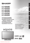
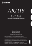
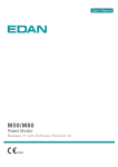
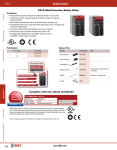
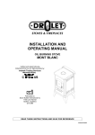
Safe T Net 100
Instruction Manual
Rev. E
Part Number 71-1420
8Jan2008
© 2007 Thermo Fisher Scientific Inc. All rights reserved.
Specifications, terms and pricing are subject to change. Not all products are available in all countries. Please
consult your local sales representative for details.
Thermo Fisher Scientific
Air Quality Instruments
27 Forge Parkway
Franklin, MA 02038
1-508-520-0430
www.thermo.com/aqi
WEEE Compliance
This product is required to comply with the European Union’s Waste
Electrical & Electronic Equipment (WEEE) Directive 2002/96/EC. It is
marked with the following symbol:
Thermo Fisher Scientific has contracted with one or more
recycling/disposal companies in each EU Member State, and this product
should be disposed of or recycled through them. Further information on
Thermo Fisher Scientific’s compliance with these Directives, the recyclers
in your country, and information on Thermo Fisher Scientific products
which may assist the detection of substances subject to the RoHS Directive
are available at: www.thermo.com/WEEERoHS.
Thermo Fisher Scientific
WEEE Compliance
WARNING
THIS INSTRUMENT IS DESIGNED TO DETECT ONE OR MORE OF
THE FOLLOWING:
FLAMMABLE VAPORS, OXYGEN CONTENT, AND/OR TOXIC GAS AND TO
GIVE WARNING BEFORE THEY REACH HARMFUL CONDITIONS. IN ORDER
TO ENSURE THAT IT WILL WARN OF DANGEROUS CONCENTRATIONS, IT
IS ESSENTIAL THAT THE INSTRUCTIONS IN THIS MANUAL, PARTICULARLY
THOSE CONCERNING START UP , OPERATION , CALIBRATION , AND
MAINTENANCE, BE READ, UNDERSTOOD, AND FOLLOWED.
NOTATION CONVENTIONS
Notices are used in this operator's manual to alert you to hazardous conditions to person or instrument and to notify you of additional information.
This operator's manual uses the following notices.
WARNING
Notifies you of potential danger that can result in personal injury
or death.
CAUTION
Notifies you of potential damage to equipment.
NOTE
Notifies you of additional or critical information.
SERVICE LOCATIONS
For additional assistance, Environmental Instruments Division has service available from
exclusive distributors worldwide. Contact one of the phone numbers below for product
support and technical information or visit us on the web at www.thermo.com/aqi.
1-866-282-0430 Toll Free
1-508-520-0430 International
Warranty
Seller warrants that the Products will operate or perform substantially in
conformance with Seller's published specifications and be free from defects
in material and workmanship, when subjected to normal, proper and
intended usage by properly trained personnel, for the period of time set
forth in the product documentation, published specifications or package
inserts. If a period of time is not specified in Seller’s product
documentation, published specifications or package inserts, the warranty
period shall be one (1) year from the date of shipment to Buyer for
equipment and ninety (90) days for all other products (the "Warranty
Period"). Seller agrees during the Warranty Period, to repair or replace, at
Seller's option, defective Products so as to cause the same to operate in
substantial conformance with said published specifications; provided that
(a) Buyer shall promptly notify Seller in writing upon the discovery of any
defect, which notice shall include the product model and serial number (if
applicable) and details of the warranty claim; (b) after Seller’s review, Seller
will provide Buyer with service data and/or a Return Material
Authorization (“RMA”), which may include biohazard decontamination
procedures and other product-specific handling instructions; and (c) then,
if applicable, Buyer may return the defective Products to Seller with all
costs prepaid by Buyer. Replacement parts may be new or refurbished, at
the election of Seller. All replaced parts shall become the property of Seller.
Shipment to Buyer of repaired or replacement Products shall be made in
accordance with the Delivery provisions of the Seller’s Terms and
Conditions of Sale. Consumables, including but not limited to lamps,
fuses, batteries, bulbs and other such expendable items, are expressly
excluded from the warranty under this warranty.
Notwithstanding the foregoing, Products supplied by Seller that are
obtained by Seller from an original manufacturer or third party supplier are
not warranted by Seller, but Seller agrees to assign to Buyer any warranty
rights in such Product that Seller may have from the original manufacturer
or third party supplier, to the extent such assignment is allowed by such
original manufacturer or third party supplier.
In no event shall Seller have any obligation to make repairs, replacements
or corrections required, in whole or in part, as the result of (i) normal wear
and tear, (ii) accident, disaster or event of force majeure, (iii) misuse, fault
or negligence of or by Buyer, (iv) use of the Products in a manner for which
they were not designed, (v) causes external to the Products such as, but not
limited to, power failure or electrical power surges, (vi) improper storage
and handling of the Products or (vii) use of the Products in combination
with equipment or software not supplied by Seller. If Seller determines
that Products for which Buyer has requested warranty services are not
Thermo Fisher Scientific
Warranty
covered by the warranty hereunder, Buyer shall pay or reimburse Seller for
all costs of investigating and responding to such request at Seller's then
prevailing time and materials rates. If Seller provides repair services or
replacement parts that are not covered by the warranty provided in this
warranty, Buyer shall pay Seller therefor at Seller's then prevailing time and
materials rates. ANY INSTALLATION, MAINTENANCE, REPAIR,
SERVICE, RELOCATION OR ALTERATION TO OR OF, OR
OTHER TAMPERING WITH, THE PRODUCTS PERFORMED BY
ANY PERSON OR ENTITY OTHER THAN SELLER WITHOUT
SELLER'S PRIOR WRITTEN APPROVAL, OR ANY USE OF
REPLACEMENT PARTS NOT SUPPLIED BY SELLER, SHALL
IMMEDIATELY VOID AND CANCEL ALL WARRANTIES WITH
RESPECT TO THE AFFECTED PRODUCTS.
THE OBLIGATIONS CREATED BY THIS WARRANTY
STATEMENT TO REPAIR OR REPLACE A DEFECTIVE PRODUCT
SHALL BE THE SOLE REMEDY OF BUYER IN THE EVENT OF A
DEFECTIVE PRODUCT. EXCEPT AS EXPRESSLY PROVIDED IN
THIS WARRANTY STATEMENT, SELLER DISCLAIMS ALL
OTHER WARRANTIES, WHETHER EXPRESS OR IMPLIED, ORAL
OR WRITTEN, WITH RESPECT TO THE PRODUCTS,
INCLUDING WITHOUT LIMITATION ALL IMPLIED
WARRANTIES OF MERCHANTABILITY OR FITNESS FOR ANY
PARTICULAR PURPOSE. SELLER DOES NOT WARRANT THAT
THE PRODUCTS ARE ERROR-FREE OR WILL ACCOMPLISH
ANY PARTICULAR RESULT.
Warranty
Thermo Fisher Scientific
TABLE OF CONTENTS
Chapter 1
Introduction
Overview . . . . . . . . . . . . . . . . . . . . . . . . . . . . . . . . . . . . . . . . . . . . . . . . 1
Description . . . . . . . . . . . . . . . . . . . . . . . . . . . . . . . . . . . . . . . . . . . . . . . 1
Application. . . . . . . . . . . . . . . . . . . . . . . . . . . . . . . . . . . . . . . . . . . . . . . 2
Accessories. . . . . . . . . . . . . . . . . . . . . . . . . . . . . . . . . . . . . . . . . . . . . . . 3
Specifications . . . . . . . . . . . . . . . . . . . . . . . . . . . . . . . . . . . . . . . . . . . . . 4
Chapter 2
Funtional Description
Overview . . . . . . . . . . . . . . . . . . . . . . . . . . . . . . . . . . . . . . . . . . . . . . . . 5
Internal Descriptiion . . . . . . . . . . . . . . . . . . . . . . . . . . . . . . . . . . . . . . . 6
Chapter 3
Installation
Mounting . . . . . . . . . . . . . . . . . . . . . . . . . . . . . . . . . . . . . . . . . . . . . . . 15
Wiring . . . . . . . . . . . . . . . . . . . . . . . . . . . . . . . . . . . . . . . . . . . . . . . . . 16
Start Up . . . . . . . . . . . . . . . . . . . . . . . . . . . . . . . . . . . . . . . . . . . . . . . . 22
Removal . . . . . . . . . . . . . . . . . . . . . . . . . . . . . . . . . . . . . . . . . . . . . . . . 23
Chapter 4
Maintenance
Overview . . . . . . . . . . . . . . . . . . . . . . . . . . . . . . . . . . . . . . . . . . . . . . . 25
Troubleshooting . . . . . . . . . . . . . . . . . . . . . . . . . . . . . . . . . . . . . . . . . . 26
Chapter 5
Accessories
Overview . . . . . . . . . . . . . . . . . . . . . . . . . . . . . . . . . . . . . . . . . . . . . . . 31
DC Power Supply with backup battery . . . . . . . . . . . . . . . . . . . . . . . . 31
Alarm Horn . . . . . . . . . . . . . . . . . . . . . . . . . . . . . . . . . . . . . . . . . . . . . 41
AC Line Cord. . . . . . . . . . . . . . . . . . . . . . . . . . . . . . . . . . . . . . . . . . . . 41
Chapter 6
Gas Detection
Overview . . . . . . . . . . . . . . . . . . . . . . . . . . . . . . . . . . . . . . . . . . . . . . . 43
Appendix A
Parts List . . . . . . . . . . . . . . . . . . . . . . . . . . . . . . . . . . . . . . . . . . . . . . . 47
71-1420 - REV E
ix
Chapter
1
INTRODUCTION
Overview
This chapter briefly describes the Safe T Net 100 and its applications. It also
describes the Safe T Net 100's accessories and features. Expanded
descriptions appear in later chapters.
FAIL
PLOT WARM ALARM
TYPE 100
GAS MONITOR
RESET
Figure 1-1 Safe T Net 100 Gas Monitor
Description
Safe T Net is a family of fixed-instrument, continuous-monitoring systems.
The Safe T Net 100 is a single-point system. It detects combustible gas,
toxic gas, or oxygen content at one location. The Safe T Net 100 displays the
current gas reading and warns you of hazardous gas concentration conditions
with audible and visual alarms at two preset alarm levels.
71-1420 - REV E
1
Safe T Net 100 Operator’s Manual
Application
The Safe T Net 100 is capable of detecting many gases. Tables 6-1 and 6-2
list the gas detection options offered for the Safe T Net 100. These options
have many applications. Among the applications are the following:
• Hospitals
• Public utilities
• Landfills
• Petrochemical plants
• Semiconductor manufacturing
• Wastewater treatment
• Oil fields and refineries
• Paper mills
• Leather tanneries
• Mining and metals industry
• Parking garages
• Grain storage silos
• Gasoline generators and engines
• Furnaces
• Lumber drying kilns
2
71-1420 - REV D
Introduction
Accessories
Table 1-1 provides a brief description of the Safe T Net 100’s standard and
optional accessories. See Chapter 5, Accessories, for more detailed
descriptions.
Table 1-1
Standard and Optional Accessories
Accessory
Description
Safe T Net 100
Operator’s Manual*
Includes detailed installation, operation,
maintenance, and calibration procedures for
the Safe T Net 100.
Safe T Net 100
Quick Reference Card*
A brief description of procedures you
commonly perform at the monitoring area.
DC Power Supply with Backup
Battery
Provides the Safe T Net 100 with a primary
DC power source, and backup power if the
primary power source fails.
Alarm Horn
Repeats Safe T Net 100’s audible alarms to a
remote area.
AC Line Cord
3-conductor wire for AC power connection.
* Supplied as a standard accessory for the Safe T Net 100.
71-1420 - REV D
3
Safe T Net 100 Operator’s Manual
Specifications
Table 1-2
Housing
Fiberglass with polycarbonate window
(rated NEMA 4X)
Dimensions
10.94 in. H x 8.5 in. W x 6.25 in. D
(278 mm x 216 mm x 158 mm)
Weight
8 lbs. (approximate)
3.6 kg (approximate)
Power source
100 to 130 VAC; 200 to 260 VAC;
or 12 to 16 VDC1
Temperature range
-4°F (-20°C) to 113°F (45°C)
Humidity range
0 to 95% RH (non-condensing)
Controls
RESET, ADJ, and CAL buttons; range selector and
alarm logic switches; WARN, ALARM, and DLY
adjust potentiometers
Alarm delay setting
1 seconds2
Fail delay setting
2 seconds2
Relays
3 amps @ 240 VAC (resistive)
5 amps @ 120 VAC (resistive)
5 amps @ 24 VDC (resistive)
Standard accessories
Operator’s manual, quick reference card
Optional accessories
Test kit, AC line cord; alarm horn;
DC Power Supply with Backup Battery
1
2
4
Specifications
Unit must be ordered for nominal 100 to 130 VAC or 200 to 260 VAC.
Either version can also be operated from 12-16 VDC
User-adjustable
71-1420 - REV D
Chapter
2
FUNCTIONAL DESCRIPTION
Overview
This chapter describes the internal components of the Safe T Net 100. All
internal components are attached or connected to the main circuit board. A
screw in each corner of the main circuit board secures the board to the
housing. Each component is identified on the circuit board by a printed
designation. The designations are noted in this chapter in parenthesis (XX#)
next to the component heading.
To gain access to the interior of the Safe T Net 100:
1. Pull the bottom of both security latches forward (toward the housing
door).
2. Push the housing door back, and release the top of both latches from
the catches on the housing door.
3. Open the housing door.
71-1420 - REV D
5
Safe T Net 100 Operator’s Manual
Internal Description
This section describes the internal components of the Safe T Net 100.
$&3RZHU
$&)XVH
7HUPLQDO6WULS
$ODUP5HOD\V
5DQJH6HOHFWRU
$GDSWHU&DUG
7%
$ODUP$GMXVW
3RWHQWLRPHWHUV
.
$ODUP'LVDEOH
%XWWRQ
.
6
&$/
6
$'-
:DUQ$ODUP
:$51
.
'LVSOD\%XWWRQ
53 $/$50
53 '/<
)
53 $
67$ 1' $ 5'
6
)$ ,/
67( $ '</2*,&
$ODUP/RJLF
23 7, 216
)/$ 6+ /2*,&
( 1 21 : 51
' (( 1 :5 1
( 1 21 $ /0
' (( 1 $ /0
,1 & 5:5 1
' (& 5 :51
/$7 &+ : 51
,1 & 5$ /0
/$7 &+ $ /0
)
6ZLWFK
)$ ,/
$ 872 567:51
' (& 5 $/0
$ 872 567$ /0
$
7%
6(1625
6(1625
6(1625
*8$5'
%$
%$f
5( &
5( &f
7
'&)XVH
7UDQVIRUPHU
6HQVRU7HUPLQDO
6WULS
Figure 2-1 Internal Component Location
6
71-1420 - REV D
Functional Description
AC Power Terminal Strip (TB1)
NOTE
See Chapter 3, Installation, for complete wiring procedures.
This 12-point terminal strip is on the left side of the main circuit board (see
Figure 2-1). Each terminal is labeled and numbered. The labels are printed
on the circuit board directly to the left of the terminal strip. They describe
each terminal’s function. The numbers are on the left side of the terminal
strip, and are numbered 1 through 12.
7%
&
5HOD\2XWSXW
&RQQHFWLRQV
<
$
/
(
5
1&
0
5
$
/
$
12
<
$
/
(
5
1&
12
1&
$
)
12
+
$&3RZHU
&RQQHFWLRQ
(
1
,
/
&
$
&
<
$
/
(
5
/
,
&
1
5
$
:
1
*
Figure 2-2 AC Power Strip
TERMINALS 10 THROUGH 12
The bottom three (10, 11, and 12) terminals (AC LINE) are for AC power
connection (see Figure 2-2). They are labeled H (hot), N (neutral), and G
(ground).
71-1420 - REV D
7
Safe T Net 100 Operator’s Manual
TERMINALS 1 THROUGH 9
The top nine (1 through 9) terminals are for relay output connections (see
Figure 2-2). The ALARM, WARN, and FAIL relay outputs each have the
following terminals: C (common), N.C. (normally closed), and N.O.
(normally open). You may use the relay output terminals to connect external
alarms or alarm responses. The relay contacts are isolated single-pole,
double-throw (SPDT) contacts and are not fused.
Sensor Terminal Strip (TB2)
This 8-point terminal strip is on the lower right side of the main circuit board
(see Figure 2-1). Each terminal is labeled and numbered. The labels are
printed on the circuit board directly to the right of the terminal strip. They
describe each terminal’s function. The numbers are on the right side of the
terminal strip, and are numbered 8 through 1 from top to bottom.
7%
6(1625
6(1625
6(1625
*8$5'
%$
%$
5(&
5(&
'HWHFWRU&RQQHFWLRQV
'&3RZHU&RQQHFWLRQ
5HFRUGHU2XWSXW&RQQHFWLRQ
Figure 2-3 Sensor Terminal Strip
TERMINALS 6 THROUGH 8
The top three terminals (6, 7, and 8) are for wiring connections from the
detector (see Figure 2-3). They are labeled SENSOR 6, SENSOR 7, and
SENSOR 8.
TERMINAL 5
Terminal 5 is an additional wiring connection if you install the detector at a
remote location (see Figure 2-3). It is labeled GUARD.
8
71-1420 - REV D
Functional Description
TERMINALS 3 AND 4
Terminals 3 and 4 are for DC power connections (see Figure 2-3). They are
labeled +12BA (terminal 4) and BA- (terminal 3).
TERMINALS 1 AND 2
Terminals 1 and 2 are for recorder output connections (see Figure 2-3). They
are labeled REC+ (terminal 2) and REC- (terminal 1). The output at these
connections is 4 to 20 mA. You can connect a recording or logging device to
terminals 1 and 2 to record the Safe T Net 100’s readings.
Alarm Relays (K1, K2, K3)
The alarm relays are to the right of the AC power terminal strip (see Figure
2-1). The relays are from top to bottom alarm (K1), warn, (K2), and fail
(K3). The applicable relay activates when the Safe T Net 100 is in a warn,
alarm, or fail condition. When the relay activates, it is either energized or deenergized. Switches 3 and 4 of the alarm logic switch select normally
energized or normally de-energized relay operation.
The relay contacts are isolated, and are rated for 3 amps at 240 VAC and 5
amps at 24 VDC and 115 VAC (resistive.)
Transformer (T1)
The transformer is near the lower left side of the main circuit board (see
Figure 2-1). It converts the incoming AC power to nominal 12 VAC. The
lower AC voltage is then converted to DC power for operation of the
circuits.
Range Selector (S1)
The range selector is a 10-position rotary switch near the center of the main
circuit board (see Figure 2-1). It selects the detection range of the Safe T Net
100. An arrow in the center of the switch indicates the current position of the
Range Selector.
CAUTION
Do not adjust the range selector. It is factory-set to match the
sensor/transmitter supplied with the Safe T Net 100.
71-1420 - REV D
9
Safe T Net 100 Operator’s Manual
Alarm Logic Switch (S4)
The alarm logic switch is below and to the right of the range selector (see
Figure 2-1). It has eight, 2-position switches. The alarm logic switch controls
various functions of the Safe T Net 100’s visual and audible alarms and relay
outputs. Each of the eight switches is labeled on the main circuit board and
numbered on the switch. Each switch and its function is described below
from top to bottom.
NOTE
The Safe T Net 100 “reads” the alarm logic switch when it initially
receives incoming power. To adjust any of the functions described
below, disconnect the incoming power source, adjust the alarm logic
switch, then re-connect the incoming power source.
SWITCH #1
Switch #1 controls the fail circuit. It is factory-set, and should not be useradjusted.
SWITCH #2
Switch #2 controls the alarm logic of the Safe T Net 100. The left position is
labeled STEADY LOGIC. In this position, the status indicator lights are
steady during a warn or alarm condition, and the WARN light flashes, the
warn relay de-energizes, and the buzzer silences (in warn condition only) if
you press the RESET button.
The right position is labeled FLASH LOGIC. In this position, the status
indicator lights flash during a warn or alarm condition, and are steady if you
press the RESET button. You cannot silence the buzzer or de-energize the
relays until the display reading indicates a normal condition and you press
the RESET button.
Standard factory setting is to the left (STEADY LOGIC).
SWITCH #3
Switch #3 controls the warn relay. The left position is labeled EN ON
WRN. In this position, the warn relay is de-energized in normal condition,
and energizes when the Safe T Net 100 is in warn condition. The right
position is labeled DE-EN WRN. In this position, the warn relay is
energized in normal condition, and de-energizes when the Safe T Net 100 is
in warn condition.
Standard factory setting is to the left (EN ON WRN).
10
71-1420 - REV D
Functional Description
SWITCH #4
Switch #4 controls the alarm relay. The left position is labeled EN ON
ALM. In this position, the alarm relay is normally de-energized, and
energizes when the Safe T Net 100 is in alarm condition. The right position
is labeled DE-EN ALM. In this position, the alarm relay is normally
energized, and de-energizes when the Safe T Net 100 is in alarm condition.
Standard factory setting is to the left (EN ON ALM).
SWITCH #5
Switch #5 defines a warn condition. The left position is labeled INCR
WRN. In this position, the Safe T Net 100 defines a warn condition as an
increasing reading that reaches the preset warn level. The right position is
labeled DECR WRN. In this position, the Safe T Net 100 defines a warn
condition as a decreasing reading that falls to the preset warn level.
Standard factory setting is to the left (INCR WRN).
SWITCH #6
Switch #6 controls the resetting of the warn circuit when a warn condition
clears. The circuit operates according to the logic selected by Switch #2.
The left position is labeled LATCH WRN. In this position, you must
manually reset the warn circuit by pressing the RESET button if the
Safe T Net 100 is or was in a warn condition.
The right position is labeled AUTO RST WRN. In this position, the warn
circuit automatically resets when the display reading falls below the preset
warn level.
Standard factory setting is to the left (LATCH WRN) for all versions except
oxygen. Standard factory setting is to the right (AUTO RST WRN) for the
oxygen version.
SWITCH #7
Switch #7 defines an alarm condition. The left position is labeled INCR
ALM. In this position, the Safe T Net 100 defines an alarm condition as an
increasing reading that reaches the preset alarm level. The right position is
labeled DECR ALM. In this position, the Safe T Net 100 defines an alarm
condition as a decreasing reading that falls to the preset alarm level.
Standard factory setting is to the left (INCR ALM) for all versions except
oxygen. Standard factory setting is to the right (DECR ALM) for the
oxygen version.
71-1420 - REV D
11
Safe T Net 100 Operator’s Manual
SWITCH #8
Switch #8 controls the de-activation of the alarm circuit when an alarm
condition clears. The left position is labeled LATCH ALM. In this position,
you must manually reset the alarm circuit after the display reading falls
below the preset alarm level.
The right position is labeled AUTO RST ALM. In this position, the alarm
circuit automatically resets itself when the display reading falls below the
preset alarm level.
Standard factory setting is to the left (LATCH ALM) for all versions except
oxygen. Standard factory setting is to the right (AUTO RST ALM) for the
oxygen version.
Alarm Adjust Potentiometers
Three adjustment potentiometers are on the right side of the main circuit
board. They are above and to the right of the alarm logic switch (see Figure
2-1). The alarm delay is factory-set as shown in Table 1-2, Specifications.
The warn and alarm level are factory-set as shown in the transmitter
Operator’s Manual. You can adjust the potentiometers with a small, flatblade screwdriver. The potentiometers are marked WARN, ALRM, and
DLY.
WARN (RP1)
The WARN potentiometer controls the reading at which the warn circuit
activates. A screw on the potentiometer allows you to adjust the warn
setting.
ALRM (RP2)
The ALRM potentiometer controls the reading at which the alarm circuit
activates. A screw on the potentiometer allows you to adjust the alarm
setting.
DLY (RP3)
The DLY potentiometer controls the delay setting. You can adjust this
potentiometer to delay the activation of the indicator lights, buzzer, and
relays from 0 to 16 seconds after a warn, alarm, or fail condition exists. A
screw on the potentiometer allows you to adjust the delay setting.
The alarm delay reduces false alarms due to electrical noise and radio
frequency interference (RFI).
12
71-1420 - REV D
Functional Description
Alarm Disable Button (S2)
The alarm disable button is a push-button switch directly above and to the
right of the alarm adjust potentiometers (see Figure 2-1). It is marked CAL.
When you push it, this button disables the warn and alarm circuits for
5 minutes while you perform calibration or other maintenance procedures.
NOTE
The WARN and ALARM indicator lights are still active and the
reading on the display screen flashes after you disable the warn and
alarm circuits.
NOTE
The alarm disable button disables the warn and alarm circuits 5
minutes from the time you push it. Pushing the button several times
does not accumulate the time that the circuits are disabled.
The alarm disable button also displays the current alarm delay setting after
you press the warn/alarm display button twice. See Chapter 4, Maintenance,
for a description of this procedure.
Warn/Alarm Display Button (S3)
The warn/alarm display button is directly to the right of the alarm disable
button (see Figure 2-1). It is marked ADJ. When you push it, the current
warn and alarm settings are shown on the display screen. See Chapter 4,
Maintenance, for a description of this procedure.
Fuses
Two fuses protect the power circuitry from internal failure of the Safe T Net
100.
AC FUSE (F1)
The AC fuse is above the transformer (see Figure 2-1). It protects the AC
line circuitry, and it is rated at 0.5 amp. A cover on the AC fuse protects you
from accidental shock.
DC FUSE (F2)
The DC fuse is below the alarm logic switch (see Figure 2-1). It protects the
DC line circuitry, and it is rated at 1.0 amp.
71-1420 - REV D
13
Safe T Net 100 Operator’s Manual
Adapter Card
The adapter card plugs into the top right corner of the main circuit board (see
Figure 2-1). A guide secures the adapter card to the circuit board. An edge
connector allows electrical connection to the main circuit board.
A 0.5 amp fuse is mounted near the front of the card, and protects the
internal power supply from short circuit conditions that might occur at the
remote transmitter or in the external wiring. Test points and potentiometers
are for factory set-up.
CAUTION
Do not adjust the potentiometers adjustment may disturb factory
settings.
14
71-1420 - REV D
Chapter
3
INSTALLATION
Mounting
LQ
FP
LQ
FP
LQ
FP
LQ
FP
Figure 3-1 Outline and Mounting Dimensions, Safe T Net 100
CAUTION
The Safe T Net 100 is suitable for installation only in a nonhazardous environment (where general purpose equipment is
used). The Safe T Net 100 is not suitable for installation in Class I,
Division 1 or Division 2 areas.
71-1420 - REV D
15
Safe T Net 100 Operator’s Manual
1. Select a convenient mounting area.
When you select the mounting area, consider the following (see
Figure 3-1):
• Is a local power source available?
• Is there enough room to open the housing door?
• Is there enough room to make wiring connections through the
conduit hubs?
• Is there enough room to attach the test cup to the detector (if it
is mounted directly to the Safe T Net 100) during the calibration
procedure.
2. If the housing door is unlatched, close the housing door, place the top
of each latch on its catch on the housing door, and push the bottom of
each latch toward the back of the housing until the latch locks.
3. Position the Safe T Net 100 on a vertical surface at approximately eye
level (4 1/2 to 5 feet from the floor).
4. Four mounting feet are attached to the back of the housing at each
corner. Secure the housing to the vertical surface with 1/4 in. screws
through each mounting foot.
Wiring
This section describes detector, external alarm, recorder output, AC power,
and DC power wiring procedures.
CAUTION
Make all wiring connections in conduit through the hubs on the
bottom of the housing. Do not wire power and detector wiring in
the same conduit.
Detector Wiring
INTERNAL AMPLIFIER VERSIONS
The internal amplifier versions of the Safe T NET 100 are furnished with the
detector wiring already installed. Refer to the appropriate manual insert for
information on wiring the internal amplifier versions.
REMOTE AMPLIFIER VERSIONS
WARNING
Make sure all power to the Safe T Net 100 is disconnected or
turned off during all wiring procedures.
16
71-1420 - REV D
Installation
1. Use a 2- or 3-conductor shielded cable, or run the wiring in metal
conduit to reduce the possibility of RFI (Radio Frequency
Interference) or EMI (Electromagnetic Interference).
2. Run the wires or cable through the conduit hub to the right of the
buzzer on the Safe T Net 100 housing. Locate the sensor terminal
strip at the bottom right of the Safe T Net 100 main printed circuit
board.
3. If you are using shielded cable, connect the shield wire to the screw
on the top of the conduit hub.
4. Connect the wires to the sensor terminal strip as shown in the table
below.
Table 3-1
STN 100 Sensor terminal strip
Detector/Transmitter
Type
Terminal 6
(-)
Terminal 7
(FB)
Terminal 8
(+)
FX-SMT (LEL)
TB1-3 (-)
TB1-2 (FB)
TB1-1 (+)
FX-SMT/SMTn (Toxic/O2)
No connection
TB1-2 (FB)
TB1-1 (+)
FX-IR
TB3-3 (-)
TB3-2 (FB)
TB3-1 (+)
Standard (LEL)
-
FB
+
Standard (Toxic/O2)
No connection
FB
+
Standard
(sample-draw, all gases)
-12/24V
OUT FB
+12/24V
External Alarm Wiring
If you plan to use external alarms (horn, strobe, process control, etc.),
connect them at this time.
CAUTION
External alarms are controlled by the Safe T Net 100’s relays. The
relays are rated for 5 amps maximum. Do not connect any device
with a current load that exceeds the limits of the relay.
1. Open the housing door, and locate the AC power terminal strip. It is
on the left side of the main circuit board.
2. Run the wiring of the external alarm through the conduit hub to the
left of the buzzer.
71-1420 - REV D
17
Safe T Net 100 Operator’s Manual
3. Connect the wiring (see Figure 3-2) to the appropriate relay
connection (ALARM, WARN, or FAIL). Connect the positive or hot
lead of the external alarm device to C (common). Connect the
positive or hot lead of the external alarm’s power source to N.C.
(normally closed) or N.O. (normally open). Connect the negative or
neutral lead of the external alarm’s power source to the negative or
neutral lead of the alarm device.
-(N)
+(H)
External Alarm
Device
TB1
C
C
N.C.
N.C.
N.O.
N.O.
Safe T Net 100 Relay
(shown in de-energized state)
-(N)
Power Source
+(H)
Safe T Net 100
AC Power
Terminal Strip
Figure 3-2 External Alarm Wiring
4. Test the connection by gently pulling the leads from the terminal
connections.
NOTE
The alarm and warn relays are de-energized in normal operation, and
energize when the Safe T Net 100 is in alarm or warn condition. To
energize the relays in normal condition, and de-energize them in alarm
or warn conditions, place switches 3 and 4 of the alarm logic switch to
the right before you plug in or turn on the incoming power. N.O.
(normally open) and N.C. (normally closed) describe the condition of
the relay when it is de-energized. If the relay is energized in normal
operation, N.C. is open and N.O. is closed.
18
71-1420 - REV D
Installation
Recorder Output Wiring
1. Open the housing door, and locate the sensor terminal strip. It is on
the lower right corner of the main circuit board.
2. Run the leads from the recording device through the hub to the left of
the buzzer.
3RVLWLYH
1HJDWLYH
7%
5(&
5(&
Figure 3-3 Recorder Output Wiring
3. Connect the leads to terminals 1 and 2 of the sensor terminal strip (see
Figure 3-3). Connect the positive (+) lead to REC + (terminal 2) and
the negative (–) lead to REC- (terminal 1).
CAUTION
The maximum input impedance of the recording device may not
exceed 400 ohms.
4. Test the connection by gently pulling the leads from the terminal
connections.
AC Power Wiring
WARNING
Make connections at the Safe T Net 100 terminal strip before you
plug in or turn on the AC power. Before making any wiring
adjustments, always verify that the AC power source is not live.
1. Open the housing door, and locate the AC power terminal strip. It is
on the left side of the main circuit board.
71-1420 - REV D
19
Safe T Net 100 Operator’s Manual
2. Run an AC power line through the conduit hub to the left of the
buzzer.
If you use the optional AC line cord, screw a cable bushing into the
conduit hub to the left of the buzzer.The bushing is supplied as part of
the AC line cord accessory.
3. Connect the AC line to terminals 10, 11, and 12 of the AC power
terminal strip (see Figure 3-4). Connect the hot (black) lead to
H (terminal 10), the neutral (white) lead to N (terminal 11), and the
ground (green) lead to G (terminal 12).
7%
+ (
1
,
/
&
$
1 *
1H
XW
*U UDO
RX
QG
+R
W
Figure 3-4 AC Power Wiring
4. Test the connection by gently pulling the leads from the terminal
connections.
20
71-1420 - REV D
Installation
CAUTION
Make sure the operating voltage (115 or 220) of the Safe T Net 100
matches the voltage of the AC power source. The operating
voltage of the Safe T Net 100 is shown on a label attached to the
inside of the housing door.
DC Power Wiring
CAUTION
DC power connections are provided as a backup to the primary
AC power source for the Safe T Net 100. If AC power is
unavailable, use 12 to 18 VDC power as a primary power source
to operate the Safe T Net 100 continuously.
1. Open the housing door, and locate the sensor terminal strip. It is on
the lower right corner of the main circuit board.
2. Run a DC power cord through the conduit hub to the left of the
buzzer.
3. Connect the power cord to terminals 3 and 4 of the sensor terminal
strip (see Figure 3-5). Connect the positive (+) lead to +12BA
(terminal 4) and the negative (-) lead to BA- (terminal 3).
3RVLWLYH
1HJDWLYH
7%
5(&
5(&
Figure 3-5 DC Power Wiring
4. Test the connection by gently pulling the leads from the terminal
connections.
71-1420 - REV D
21
Safe T Net 100 Operator’s Manual
Start Up
Complete the following procedure to place the Safe T Net 100 in normal
operation.
Preparing for Start Up
1. Complete the mounting and wiring procedures described earlier in
this chapter.
2. Complete installation procedures as described in the transmitter
Operator’s manual.
3. Check to make sure that all wiring connections are secure and correct.
Introducing Incoming Power
1. Plug in or turn on the incoming power (AC and/or DC) at the power
source end.
WARNING
The warn and alarm circuits are not active for 45 seconds after
the Safe T Net 100 initially receives the incoming power. This time
delay prevents false alarms during detector warm-up.
Verifying Indicator Lights
1. After you connect or turn on the incoming power source, check the
status indicator lights on the housing door.
2. Verify the PILOT light is on. If the PILOT light is off, the Safe T Net
100 is not receiving the incoming power.
WARNING
Unplug or turn off the incoming power at the power source before
you make wiring adjustments or remove the fuse.
3. Check the AC or DC power connections in the Safe T Net 100 and at
the power source if the PILOT light is off. Also check the AC and DC
fuses.
4. The indicator lights on the housing door show the current status of the
Safe T Net 100 during the start-up procedure. Table 3-2, Start-up
Indications, shows the status indicated by each light and the suggested
response.
22
71-1420 - REV D
Installation
Table 3-2 Start-up Indications
Indicator
Light
Probable Status
Recommended Response
PILOT
Receiving power.
None
FAIL
Detector or circuitry is
broken, incomplete, or
incorrect.
1. Verify detector wiring is correct and
secure.
2. See the “Troubleshooting” section
in the transmitter Operator’s
manual.
Adapter card is not
connected or is
connected incorrectly.
1. Make sure adapter card is connected.
2. Make sure potentiometers on adapter
card face toward the circuit board
(away from the side of housing).
3. Contact Thermo Fisher Scientific for
further instruction.
Removal
1. Disconnect or turn off the incoming power at the power source end.
2. Disconnect the power wiring from the AC power terminal strip, and
pull the wires out of the housing through the conduit hub. If the
optional AC line cord is used, leave it connected to the terminal strip.
WARNING
Make sure power to the relay circuits is turned off before you
perform Step 3.
3. Disconnect and remove any other connections made to the AC power
terminal strip.
4. Disconnect and remove all connections made to the sensor terminal
strip other than the detector connections.
5. Remove the mounting screws from the mounting feet or interior
mounting slots at each corner of the Safe T Net 100 housing.
6. Protect the Safe T Net 100 or any components of the Safe T Net 100 if
you return it for repair.
71-1420 - REV E
23
Safe T Net 100 Operator’s Manual
24
71-1420 - REV D
Chapter
4
MAINTENANCE
Overview
This Chapter describes corrective maintenance procedures for the Safe T Net
100. It includes a troubleshooting guide and procedures for adjusting the
alarm levels and the alarm delay.
WARNING
Perform maintenance activities in a non-hazardous environment.
71-1420 - REV D
25
The following is a troubleshooting guide. It describes the symptoms, probable causes, and recommended actions for problems you
may encounter.
Table 4-1
Troubleshooting
Condition
Symptom(s)
Probable Cause(s)
Recommended Action
No Power
• PILOT indicator light off.
• Incorrect or
incomplete power
circuit.
1. Verify correct connection at the power source.
• No reading on the display
screen
2. Verify and correct (if necessary) the connections at
terminals 10, 11, and 12 of the AC power terminal strip
(AC power) or terminals 3 and 4 of the sensor terminal
strip (DC power). See Chapter 3, Installation.
3. Check and replace (if necessary) the AC and DC fuses.
4. Check ribbon cable connection to display screen (inside
housing door) and top left corner of main circuit board.
Frequent
Alarms
• Frequent or false alarms, but
no change in zero reading.
71-1420 - REV D
• False readings due to
Radio Frequency
Interference (RFI)
and/or electrical
noise.
1. Increase the Alarm delay setting. See the “Adjusting the
Alarm Delay” section at the end of this chapter.
Safe T Net 100 Operator’s Manual
26
Troubleshooting
71-1420 - REV E
Table 4-1
Troubleshooting (Continued)
Condition
Symptom(s)
Probable Cause(s)
Recommended Action
Incorrect
Alarm
Logic
• Audible and visual alarms
and alarm relays do not
operate as described in
Chapter 2, Functional
Description.
• Alarm logic switch
adjusted while power
is on.
1. Adjust the alarm logic switch to your preferred alarm
logic.
• Bad circuitry.
2. Unplug or turn off the incoming power at the power
source.
3. Plug in or turn on the incoming power at the power source.
4. If incorrect operation of the alarms or alarm relays
continues, contact Thermo Fisher Scientific for further
instruction.
Accidental
Disable
• Display reading is blinking.
• Buzzer is silent.
• Alarm disable button
(marked CAL)
pressed.
1. Press the RESET button to return to normal operation.
• Relays are disabled.
Maintenance
27
Safe T Net 100 Operator’s Manual
Adjusting the Alarm Levels
Standard warn and alarm levels are shown in Chapter 6, Gas Detection. To
adjust the alarm levels:
1. Unlatch and open the housing door. Locate the warn/alarm display
button (marked ADJ) and the alarm adjust potentiometers (marked
WARN and ALRM).
The warn/alarm display button is on the right side of the main circuit
board, and is to the left of the adapter card. The alarm adjust
potentiometers are directly below the warn/alarm display button.
2. Push the warn/alarm display button (ADJ) once. The current warn
level is displayed on the display screen and the WARN light blinks.
NOTE
The warn and alarm level and alarm delay are shown on the display
screen for 30 seconds. The Safe T Net 100 returns to normal operation
if you do not continue the procedure in 30 seconds.
3. Adjust the warn level on the display screen to your preferred warn
level. Turn the warn adjust potentiometer clockwise to increase the
warn level; turn the warn adjust potentiometer counterclockwise to
decrease the warn level.
NOTE
To return to normal operation, push the warn/alarm display button
twice. To adjust the alarm level, continue with Step 4.
4. Push the warn/alarm display button. The current alarm level is
displayed on the display screen and the ALARM light blinks.
5. Adjust the alarm level on the display screen to your preferred alarm
level. Turn the alarm adjust potentiometer clockwise to increase the
alarm level; turn the alarm adjust potentiometer counterclockwise to
decrease the alarm level.
6. Push the warn/alarm display button to return to normal operation.
7. Close and latch the housing door.
28
71-1420 - REV D
Maintenance
Adjusting the Alarm Delay
The alarm delay feature delays the operation of the status indicator lights,
buzzer, and relays during warn, alarm, or fail conditions. This delay
eliminates false alarms due to power transmissions and electrical noise. The
delay can be set from 0.0 to 16.0 seconds. The standard alarm delay and fail
delay settings are shown in Table 2-1, Specifications. To adjust the delay
settings:
1. Unlatch and open the housing door. Locate the warn/alarm display
button (marked ADJ), the alarm disable button (marked CAL) and
the delay adjust potentiometer (marked DLY).
The warn/alarm display and alarm disable buttons are on the right side
of the main circuit board, and are to the left of the adapter card. The
delay adjust potentiometer is directly below the warn/alarm display
and alarm disable buttons.
2. Push the warn/alarm display button (ADJ) twice. The current alarm
level is displayed on the display screen and the ALARM indicator
light blinks.
3. Push the alarm disable button (CAL) once. The current alarm delay
setting is displayed on the display screen and the WARN and
ALARM indicator lights blink.
NOTE
The fail delay setting is twice the setting displayed on the display
screen. If the display screen indicates an alarm delay setting of 4.5, the
actual fail delay setting is 9.0.
4. Adjust the delay setting on the display screen to your preferred setting
(0.0 to 16.0 seconds). Turn the delay adjust potentiometer clockwise
to increase the setting; turn the delay adjust potentiometer
counterclockwise to decrease the setting.
5. Push the warn/alarm display button once to return to normal
operation.
NOTE
The Safe T Net 100 automatically returns to normal operation 30
seconds after you push CAL if you do not perform Step 5.
6. Close and latch the housing door.
71-1420 - REV D
29
Safe T Net 100 Operator’s Manual
30
71-1420 - REV D
Chapter
5
ACCESSORIES
Overview
This chapter describes the Safe T Net 100’s accessories.
DC Power Supply with Backup Battery
The DC power supply with backup battery provides nominal 12 VDC power
to operate the Safe T Net 100 as a primary power source. It requires 115
VAC power for operation. In case of AC power failure, it provides a backup
power source to the Safe T Net 100 for up to 8 hours. The DC power supply
with backup battery is thermal and short circuit protected.
Thermo Fisher Scientific offers two versions of this optional accessory. One
version is UL listed, and the other version is not listed. Differences between
the two versions are described within this section.
Description
This section describes the housing and the internal components of the DC
power supply with backup battery. Internal components include the
transformer, the circuit board, and the batteries (see Figure 5-1).
HOUSING
The steel housing measures 11.2 in. (28.4 cm) x 15.4 in. (39.1 cm) x 4.3 in.
(10.9 cm). Two mounting holes are on the back of the housing near the top,
and two mounting holes are on the back of the housing near the bottom. The
housing has a total of eight knockouts for external connections. A lock near
the top of the housing door secures the housing door and locks it in place
during normal operation. A label on the inside of the housing door contains a
general installation procedure and wiring diagram.
TRANSFORMER
The transformer is near the upper left corner of the housing. It converts the
incoming AC power to DC power for operation of the backup battery and the
12 VDC output.
Two leads (white and black) extend from the left side of the transformer.
These leads are for connection to the incoming 115 VAC power source. A
grounding lug to the left of the transformer is to connect the ground wire of
the AC power wire. Two leads extend from the right side of the transformer.
These leads connect to the input terminal strip on the circuit board.
71-1420 - REV E
31
11.2 in.
Grounding Lug
Transformer
11.7 in.
[29.7 cm]
15.4 in.
[39.1 cm]
32
Battery
Battery Terminal
FAULT light
BATTERY FUSE
AC light
Input Terminal Strip
Mounting Hole
AC FUSE
Safe T Net 100 Operator’s Manual
Figure 5-1 DC Power Supply with Backup Battery
71-1420 - REV D
Accessories
CIRCUIT BOARD
The circuit board is to the right of the transformer. The circuit board contains
components that maintain the charge of the batteries. The charging circuit
brings low batteries up to full charge, and maintains the batteries at an
operating level.
Two four-point terminal strips are on the right side of the circuit board. The
upper terminal strip is the input terminal strip. It allows connection to the
transformer and one of the batteries. The lower terminal strip is the output
terminal strip. It allows connection to the Safe T Net 100 and an optional
fault indicator. If a fault condition occurs at the DC power supply with
backup battery, 12 VDC power is supplied to any indicator wired to the
FAULT OUTPUT terminal. Thermo Fisher Scientific offers a buzzer that
operates from 12 VDC for this purpose.
The non-UL version has a dip switch between the two terminal strips. The
switch is factory-set and should not be adjusted. The UL version does not
have this dip switch.
Two indicator lights on the circuit board indicate the status of the DC power
supply with backup battery. The light marked AC is to the left of the input
terminal strip. When the AC light is on, the DC power supply with backup
battery is operating from the AC power source. The light marked FAULT is
to the left of the output terminal strip. When the FAULT light is on, one or
more of the following conditions may exist: low AC power, no AC power,
blown AC FUSE, blown BATTERY FUSE, incorrect wiring connections,
and low battery. A third light below the BATTERY FUSE does not serve a
user function.
Two 10-amp fuses protect the circuitry of the circuit board. The AC FUSE is
above the input terminal strip. It protects the circuitry of the AC line. The
BATTERY FUSE is to the left of the input terminal strip. It protects the
batteries from short circuit conditions.
BATTERIES
Two sealed, lead-acid batteries are at the bottom of the housing. The
batteries are rated 12-volts at 7 ampere-hours (14 ampere-hours total) and
are rechargeable. Positive and negative terminals are on the top of the
batteries at the left side.
A wiring harness connects the two batteries. The black lead connects the
negative terminals, and the red lead connects the positive terminals. The
wiring harness is factory-installed to the input terminal strip.
71-1420 - REV E
33
Safe T Net 100 Operator’s Manual
Installation
This section describes the installation procedure for the DC power supply
with backup battery.
NOTE
If you use the DC power supply with backup battery accessory,
disregard the AC and DC power wiring procedures described in
Chapter 3, Installation. All power for the Safe T Net 100 is introduced
through this accessory.
MOUNTING
1. Open the housing door, and remove the protective foam inserts.
2. Position the housing on a vertical surface near the Safe T Net 100.
3. A mounting hole is near each corner on the back of the housing.
Secure the housing to the vertical surface with screws through each
hole. Use screws that are appropriate for the mounting surface.
WIRING
WARNING
Make all other wiring connections before you make connections to
the DC power supply with backup battery. Make sure you turn off
all AC power before you make the following wiring connections.
1. Run AC power wires through the knockout on the left side or the top
of the housing, and connect the AC line to the white and black leads
that extend from the left side of the transformer.
Connect the hot or positive (+) AC lead from the power source to the
transformer’s black lead; connect the neutral or negative (–) AC lead
from the power source to the transformer’s white lead.
WARNING
The red (+) and black (-) wires of the battery wiring harness
receive power from the batteries, and are active before the
incoming power is connected. Do not touch the wires to each other
or any other conductor while making wiring connections.
2. Confirm that the leads extending from the right side of the
transformer are connected to the terminals marked LOW VOLTAGE
AC CONNECTION on the input terminal strip. If necessary, connect
the leads to the terminals.
3. Plug in or turn on the incoming AC power at the power source end.
34
71-1420 - REV D
Accessories
4. Connect a multimeter to the terminal marked DC OUTPUT on the
output terminal strip, and verify a multimeter reading of
approximately 13.8 VDC.
Connect the positive multimeter lead to the terminal marked +;
connect the negative multimeter lead to the terminal marked –.
5. Connect a multimeter to the terminal marked BATTERY
CONNECTION on the input terminal strip, and repeat Step 4.
6. Unplug or turn off the incoming AC power at the power source end.
7. Connect the output terminal strip in the DC power supply with
backup battery to the sensor terminal strip in the Safe T Net 100 as
shown in Table 5-1.
Table 5-1
Wiring The DC Power Supply with backup
Battery to the Safe T Net 100
Output Term. Strip
(DC Power Supply)
Sensor Term. Strip
(Safe T Net 100)
DC OUTPUT (+)
Terminal 4 (+12BA)
DC OUTPUT (–)
Terminal 3 (BA–)
Run the two wires through the knockout on the right side or the top of
the accessory’s housing and the left conduit hub on the bottom of the
Safe T Net 100.
CAUTION
Make sure the wires from the DC power supply with backup
battery are connected to the correct terminals in the
Safe T Net 100. An incorrect connection may damage the Safe T
Net 100.
8. If you are using a device to indicate a fault condition at the DC power
supply with backup battery, connect the device to the terminal marked
FAULT OUTPUT on the output terminal strip.
9. Connect the positive lead of the indicator to the terminal marked +;
connect the negative lead of the indicator to the terminal marked –.
10.Connect the four leads that extend from the battery wiring harness to
the terminals on the batteries.
Connect the two red leads to the positive (+) battery terminals;
connect the two black leads to the negative (–) battery terminals.
71-1420 - REV D
35
Safe T Net 100 Operator’s Manual
CAUTION
Make sure the leads from the wiring harness are connected to the
correct battery terminals. An incorrect connection will destroy
the battery fuse.
11.Plug in or turn on the incoming AC power at the power source end.
12.Make sure the Safe T Net 100 is operating from the primary power
source (AC power). The AC light on the DC power supply with
backup battery’s circuit board and the PILOT indicator light on the
Safe T Net 100 are both on when the Safe T Net 100 is operating from
the primary power source.
36
71-1420 - REV D
71-1420 - REV E
Troubleshooting
The following table is a troubleshooting guide. It describes the symptoms, probable causes, and recommended actions for problems
you may encounter with this accessory.
Table 5-2
Troubleshooting the DC Power Supply with Backup Battery
Condition
Symptom(s)
Probable Cause(s)
Recommended Action
Fault
• FAULT light on the
circuit board is
blinking.
• Low AC power.
1. Check primary AC power source.
• No AC power.
2. Confirm that the incoming AC power connection is
correct and secure.
• Blown AC FUSE.
• Blown BATTERY
FUSE.
• Low Battery.
3. Confirm that the connection from the batteries to the
input terminal strip is correct and secure.
4. Check the continuity of the AC and BATTERY
FUSES. If necessary, replace the fuse(s) as described in
the following pages.
5. Check the condition of the batteries. If necessary,
replace the batteries as described in the following
pages.
6. If the condition continues, contact Thermo Fisher
Scientific for further instruction.
Accessories
37
Troubleshooting the DC Power Supply with Backup Battery (Continued)
Condition
Symptom(s)
Probable Cause(s)
Recommended Action
No Power
• AC light on circuit
board is not on.
• No AC power.
1. Check primary AC power source.
• Blown AC FUSE.
2. Confirm that the incoming AC power connection is
correct and secure.
3. Check the continuity of the AC FUSE. If necessary,
replace the fuse as described in the following pages.
4. If the condition continues, contact Thermo Fisher
Scientific for further instruction.
Incorrect
Output
Voltage
71-1420 - REV E
• Output between the
terminals marked DC
OUTPUT of the output
terminal strip or the
terminals marked
BATTERY
CONNECTION of the
input terminal strip is
not approximately
13.8 VDC.
• Incorrect battery
connection.
1. Confirm that the connection from the batteries to the
input terminal strip is correct and secure.
• Defective battery.
2. Check the condition of the batteries. If necessary,
replace the batteries as described in the following
pages.
3. If the condition continues, contact Thermo Fisher
Scientific for further instruction.
Safe T Net 100 Operator’s Manual
38
Table 5-2
71-1420 - REV E
Table 5-2
Troubleshooting the DC Power Supply with Backup Battery (Continued)
Condition
Symptom(s)
Probable Cause(s)
Recommended Action
No Backup
Power
• Backup power does not
operate when incoming
AC power is
interrupted.
• Blown BATTERY
FUSE.
1. Confirm that the connection from the batteries to the
input terminal strip is correct and secure.
• Incorrect battery
connection.
2. Check the continuity of the BATTERY FUSE. If
necessary, replace the fuse as described in the
following pages.
3. If the condition continues, contact Thermo Fisher
Scientific for further instruction.
Accessories
39
Safe T Net 100 Operator’s Manual
Corrective Maintenance
This section describes procedures to replace the batteries and the AC or
BATTERY FUSE.
REPLACING THE BATTERIES
Perform the following procedure to replace the batteries.
1. Unplug or turn off the incoming AC power at the power source end.
2. Unlock and open the housing door, then disconnect the battery wiring
harness leads from the input terminal strip.
3. Disconnect the wiring harness leads from the batteries, and remove
the batteries from the housing.
4. Place the replacement batteries in the same position as the old
batteries.
5. Connect the wiring harness leads to the terminals on the replacement
batteries. Connect the red leads to the positive (+) terminals; connect
the black leads to the negative (–) terminals.
6. Connect the battery wiring harness leads to the BATTERY
CONNECTION terminal on the input terminal strip. Connect the red
lead to the positive (+) terminal; connect the black lead to the
negative (–) terminal.
7. Close and lock the housing door, then plug in or turn on the incoming
AC power at the power source end.
REPLACING THE FUSES
Perform the following procedure to replace the AC or BATTERY FUSE.
1. Unplug or turn off the incoming AC power at the power source end.
2. Unlock and open the housing door, then disconnect the battery wiring
harness leads from the input terminal strip.
3. Pull the applicable fuse out of its holder.
CAUTION
For continuous protection against fire hazard and to maintain the
UL listing (for the UL version) of this accessory, replace the fuse
with the same type and rating.
4. Push the appropriate replacement fuse into the holder.
5. Connect the battery wiring harness leads to the BATTERY
CONNECTION terminal on the input terminal strip. Connect the red
lead to the positive (+) terminal; connect the black lead to the
negative (–) terminal.
40
71-1420 - REV D
Accessories
6. Close and lock the housing door, then plug in or turn on the incoming
AC power at the power source end.
Alarm Horn
The alarm horn repeats the Safe T Net 100’s audible alarms at a remote, nonhazardous location. The alarm horn is protected by a weatherproof housing.
Wire the horn to the AC power terminal strip as described in the “External
Alarm Wiring” section of Chapter 4, Installation. The horn operates on 115
VAC power. The alarm horn is an optional accessory.
The AC power terminal strip has separate relay output terminals for
ALARM, WARN, and FAIL. The alarm horn only repeats the audible
alarms for the relay output to which it is wired. For example, if the horn is
wired to the terminal marked WARN RELAY, the horn only repeats the
audible alarms of a warn condition.
NOTE
The alarm horn sounds a steady tone for all alarms. If the Safe T Net
100 sounds a pulsing tone, the alarm horn sounds a steady tone. When
the alarm horn sounds an alarm, verify the visual and audible alarms at
the Safe T Net 100 to determine the status of the Safe T Net 100.
AC Line Cord
The AC line cord is a 3-conductor cable for 115 VAC power connection. It
is 8-feet long. The AC line cord includes a 3/4 in. x 1/2 in. reducer bushing
and cord grip fitting for installation. See Chapter 4, Installation, for AC
power wiring instructions. The AC line cord is an optional accessory.
71-1420 - REV D
41
Safe T Net 100 Operator’s Manual
42
71-1420 - REV D
Chapter
6
GAS DETECTION
Overview
This chapter lists remote transmitters that can be ordered with your
Safe T Net 100. The remote transmitter includes the following:
• Amplifier
• Junction Box (if applicable)
• Sample housing (if applicable)
• Detector
• Operator’s Manual
Tables 6-1 and 6-2 indicate the gas detection options offered for the Safe T
Net 100.
Refer to the transmitter operator’s manual for information on installation,
operation, and maintenance of the transmitter.
71-1420 - REV D
43
Part Number
STD Diffusion
Part Number
STD Sample- Draw
Part Number
FX-SMT
Part Number
FX-SMTN
Ammonia (NH3)
67-0027-09
68-0020-09
67-0024-09
67-0025-09
Arsine (AsH3)
67-0027-13
68-0020-13
67-0024-13
67-0025-13
Carbon Monoxide (CO)
67-0027-01
68-0020-01
67-0024-01
67-0025-01
Chlorine (Cl2)
67-0027-04
68-0020-04
67-0024-04
67-0025-04
Chlorine Dioxide (ClO2)
67-0027-16
68-0020-16
67-0024-16
67-0025-16
65-5001
68-0005
67-0021-01
N/A
Diborane (B2H6)
67-0027-18
68-0020-18
67-0024-18
67-0025-18
Fluorine (F2)
67-0027-07
68-0020-07
67-0024-07
67-0025-07
Hydrogen Chloride (HCl)
67-0027-05
68-0020-05
67-0024-05
67-0025-05
Hydrogen Cyanide (HCN)
67-0027-08
68-0020-08
67-0024-08
67-0025-08
Hydrogen Fluoride (HF)
67-0027-06
68-0020-06
67-0024-06
67-0025-06
Hydrogen Sulfide (H2S)
67-0027-02
68-0020-02
67-0024-02
67-0025-02
Nitric Oxide (NO)
67-0027-14
68-0020-14
67-0024-14
67-0025-14
Nitrogen Dioxide (NO2)
67-0027-15
68-0020-15
67-0024-15
67-0024-15
Oxygen (O2)
67-0027-03
68-0020-03
67-0024-03
67-0025-03
Description
Combustibles
Part Number
FX-IR
67-0022-01
Safe T Net 100 Operator’s Manual
44
Table 6-1 Remote Transmitter Type Detection
71-1420 - REV D
71-1420 - REV D
Table 6-1 Remote Transmitter Type Detection (Continued)
Part Number
STD Diffusion
Part Number
STD Sample- Draw
Part Number
FX-SMT
Part Number
FX-SMTN
Ozone (O3)
67-0027-12
68-0020-12
67-0024-12
67-0025-12
Phosphine (PH3)
67-0027-10
68-0020-10
67-0024-10
67-0025-10
Silane (SiH4)
67-0027-11
68-0020-11
67-0024-11
67-0025-11
Sulfur Dioxide (SO2)
67-0027-17
68-0020-17
67-0024-17
67-0025-17
Detection Operator’s
Manual (Toxic/O2)
71-0090
71-0114
71-0085
71-0085
71-1420-10
71-1420-10
71-0085
N/A
Description
Detection Operator’s
Manual (Combustibles)
Part Number
FX-IR
71-0084
Gas Detection
45
Internal Amplifier Versions (Includes STN100 base unit and Amplifier card)
Description
Part Number
Standard Diffusion
Part Number, Detection Manual
Inserts
Carbon Monoxide (CO)
73-1422
71-1420-02
Combustibles
72-1301
71-1420-09
Hydrogen Sulfide (H2S)
73-1421
71-1420-05
Oxygen (O2)
72-1302
71-1420-07
Safe T Net 100 Operator’s Manual
46
Table 6-2
71-1420 - REV D
Appendix
A
Parts List
Table A-1 Parts List
Part No.
Description
43-4110
AC Fuse, 3AG-1/2A (AGC-1/2)
43-4181
AC and Battery Fuse, 3AG-10A (AGC-10),
for DC Power Supply with Backup Battery)
43-4232
DC Fuse (1 amp), Size F
47-1011
AC Line Cord, 8-foot
49-1551
12 VDC Battery (for DC Power Supply with
Backup Battery)
49-8103
DC Power Supply with Backup Battery
(non-UL listed)
49-8106
DC Power Supply with Backup Battery
(UL listed)
52-0005
Alarm Horn
52-1016
Buzzer (for DC Power Supply with Backup
Battery)
71-1300
Safe T Net 100 Quick Reference Card
71-1420
Safe T Net 100 Operator’s Manual
71-1420 - REV D
47
Safe T Net 100 Operator’s Manual
48
71-1420 - REV D