1
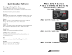
Exposure Monitoring Models SP330/SP350 SIDEPAKTM Personal Sampling Pumps User Guide 1980454, Revision A June 2003 Models SP330/SP350 SIDEPAK™ Personal Sampling Pumps User Guide June 2003 P/N 1980454, Revision A SHIP TO/MAIL TO: TSI Incorporated 500 Cardigan Road Shoreview, MN 55126-3996 USA U.S. Customer Service: (800) 861-7919/(651) 490-3838 Fax: (651) 490-3824 E-mail address: [email protected] Website: http://www.tsi.com INTERNATIONAL Customer Service: (001 651) 490-3838 Fax: (001 651) 490-3824 Copyright © TSI Incorporated / Revision A / 2003 / All rights reserved. Address TSI Incorporated / 500 Cardigan Road / Shoreview, MN 55126 / USA Fax No. (651) 490-3824 Limitation of Warranty and Liability (effective July 2000) Seller warrants the goods sold hereunder, under normal use and service as described in the operator's manual, shall be free from defects in workmanship and material for twenty-four (24) months, or the length of time specified in the operator's manual, from the date of shipment to the customer. This warranty period is inclusive of any statutory warranty. This limited warranty is subject to the following exclusions: a. Hot-wire or hot-film sensors used with research anemometers, and certain other components when indicated in specifications, are warranted for 90 days from the date of shipment. b. Parts repaired or replaced as a result of repair services are warranted to be free from defects in workmanship and material, under normal use, for 90 days from the date of shipment. c. Seller does not provide any warranty on finished goods manufactured by others or on any fuses, batteries or other consumable materials. Only the original manufacturer's warranty applies. d. Unless specifically authorized in a separate writing by Seller, Seller makes no warranty with respect to, and shall have no liability in connection with, goods which are incorporated into other products or equipment, or which are modified by any person other than Seller. The foregoing is IN LIEU OF all other warranties and is subject to the LIMITATIONS stated herein. NO OTHER EXPRESS OR IMPLIED WARRANTY OF FITNESS FOR PARTICULAR PURPOSE OR MERCHANTABILITY IS MADE. TO THE EXTENT PERMITTED BY LAW, THE EXCLUSIVE REMEDY OF THE USER OR BUYER, AND THE LIMIT OF SELLER'S LIABILITY FOR ANY AND ALL LOSSES, INJURIES, OR DAMAGES CONCERNING THE GOODS (INCLUDING CLAIMS BASED ON CONTRACT, NEGLIGENCE, TORT, STRICT LIABILITY OR OTHERWISE) SHALL BE THE RETURN OF GOODS TO SELLER AND THE REFUND OF THE PURCHASE PRICE, OR, AT THE OPTION OF SELLER, THE REPAIR OR REPLACEMENT OF THE GOODS. IN NO EVENT SHALL SELLER BE LIABLE FOR ANY SPECIAL, CONSEQUENTIAL OR INCIDENTAL DAMAGES. SELLER SHALL NOT BE RESPONSIBLE FOR INSTALLATION, DISMANTLING OR REINSTALLATION COSTS OR CHARGES. No Action, regardless of form, may be brought against Seller more than 12 months after a cause of action has accrued. The goods returned under warranty to Seller's factory shall be at Buyer's risk of loss, and will be returned, if at all, at Seller's risk of loss. Buyer and all users are deemed to have accepted this LIMITATION OF WARRANTY AND LIABILITY, which contains the complete and exclusive limited warranty of Seller. This LIMITATION OF WARRANTY AND LIABILITY may not be amended, modified or its terms waived, except by writing signed by an Officer of Seller. Service Policy Knowing that inoperative or defective instruments are as detrimental to TSI as they are to our customers, our service policy is designed to give prompt attention to any problems. If any malfunction is discovered, please contact your nearest sales office or representative, or call TSI's Customer Service department at (800) 861-7919 (USA) or (001 651) 490-3838 (International). For Technical Support call (800) 861-7397 (USA) or (001 651) 765-3777 (International). CONTENTS SAFETY INFORMATION ................................................................... III 1 UNPACKING AND PARTS IDENTIFICATION ............................ 1 SIDEPAK™ SP330 and SP350 Personal Sampling Pump Kit Photos and Accessory Descriptions .......................................... 1 2 SETTING-UP................................................................................. 9 Supplying Power to the SIDEPAKTM Personal Sampling Pump...... 9 Battery Information ........................................................................ 9 Installing the NiMH Rechargeable Battery Packs................... 9 Installing the AA Battery Pack .............................................. 10 Replacing the Cells in the AA Battery Pack.......................... 12 Using the Power Supply ....................................................... 12 Keypad Functions........................................................................ 14 3 OPERATION ............................................................................... 15 Overview...................................................................................... 15 Keypad Functions........................................................................ 15 Identifying SIDEPAK SP330 and SP350 Features........................ 16 Power Up..................................................................................... 16 Power Down ................................................................................ 17 Ready Mode ................................................................................ 17 Setup Menu........................................................................... 17 Flow Setpoint.................................................................. 17 Clear Data ...................................................................... 18 Reset All ......................................................................... 18 Set Program ................................................................... 19 Run Program .................................................................. 19 Flow Mode ................................................................................... 20 Low Flow Operation .................................................................... 20 Low Flow Adapter ................................................................. 20 High Flow Operation.................................................................... 21 Calibrating a SIDEPAK SP330/SP350 .......................................... 21 Flow Blocked Error ...................................................................... 22 4 MAINTENANCE .......................................................................... 23 Maintaining Rechargeable Battery Packs ................................... 23 Charging a NiMH Battery Pack............................................. 23 Using and Maintaining the Sorbent Tube Holders ...................... 24 Cleaning the Sorbent Tube Holders ..................................... 25 Using and Maintaining the Respirable Cyclone Kit ..................... 25 Cleaning the Cyclone............................................................ 27 Pump Service Kit for the SIDEPAK SP330/SP350 ....................... 28 Changing the Inlet Filter........................................................ 28 5 TROUBLESHOOTING................................................................ 31 i APPENDIX A ii SPECIFICATIONS....................................................................... 35 Safety Information The TSI SIDEPAK Personal Sampling Pumps are designed to collect air samples using accepted industrial hygiene principles, practices and techniques with recommended maintenance and service as required. This User Guide may not address all health and safety concerns associated with these products and their use. The end user is responsible for assessing, determining and following appropriate and applicable health and safety practices and compliance/regulatory limitations before using these products. The information contained in this document should not be construed as legal advice, opinion, or as a final authority on legal or regulatory procedures. For additional information, see TSI Limitation of Warranty and Liability on page ii of this User Guide. iii iv Chapter 1 Unpacking and Parts Identification Carefully unpack your Model SP330 or SP350 SIDEPAK™ Personal Sampling Pump from the shipping container. Use the photos and accessory descriptions below to determine which components are included with the kit or single unit you purchased. If any parts are missing, contact TSI immediately. SIDEPAK™ SP330 and SP350 Personal Sampling Pump Kit Photos and Accessory Descriptions Single-Unit Kit with 801724 Battery Pack 1 Single-Unit Kit with 801708 or 801722 Battery Pack Three-Unit Kit with 801724 Battery Pack 2 Chapter 1 Three-Unit Kit with 801708 or 801722 Battery Pack Five-Unit Kit with 801724 Battery Pack Unpacking and Parts Identification 3 Five-Unit Kit with 801708 or 801722 Battery Pack 37-mm Filter Cassette Kit (801709) 25-mm Filter Cassette Kit (801726) 4 Cyclone Kit (801721) Single Non-Adjustable Sorbent Tube Kit (801720) Chapter 1 Low Flow Adapter/Constant Pressure Controller (801699) Single Adjustable Sorbent Tube Kit (801695) Pump Service Kit (801725) Double Adjustable Sorbent Tube Kit (801696) Hard Single-Unit Carry Case 12.2” x 8” x 3.75” (1319315) Triple Adjustable Sorbent Tube Kit (801697) Unpacking and Parts Identification 5 Battery Pack (801708) Soft Single-Unit Carry Case 11.25” x 9” x 4.25” (1319289) Battery Pack, 1650 mAH (801724) Hard 3-Unit Carry Case 17” x 12.5” x 4.2” (1319316) Battery Pack, 2700 mAH (801722) Power Supply with U.S. Line Cord (2613210) 6 Hard 5-Unit Carry Case 24.25” x 19.5” x 8.75” (1319337) Chapter 1 Belt Clip for SIDEPAK Instruments (1206134) U-Tube Kit (801704) Sample Tube, Vinyl (801693) Sorbent Tube Cover (2902021) 37-mm Filter Cassette Clip (1309062) Large Sorbent Tube Cover (2902024) Unpacking and Parts Identification 25-mm Filter Cassette Clip (1309164) 7 Screwdriver, dual ended Phillips Flat (3012094) Cyclone/Filter Cassette Clip (1309157) SP330/SP350 User Guide (1980454) Luer Adapter (1611303) 8 Chapter 1 Chapter 2 Setting-Up Supplying Power to the SIDEPAKTM Personal Sampling Pump You must attach a battery pack to the SIDEPAKTM Personal Sampling Pump prior to use. There are three different TSI battery packs designed for the SP330 or SP350: 1650 and 2700 mAH rechargeable nickel-metal hydride (NiMH) battery packs and a AA battery pack that allows you to use standard AA-size batteries. You may also power the SP330 or SP350 with the power supply, with or without a battery pack attached. Both of the NiMH battery packs are approved and rated intrinsically safe. The AA battery pack is not intrinsically safe. The following battery information table provides the intrinsic safety rating information. Battery Information Charge Time* Intrinsically Safe 1650 mAH NiMH Pack (P/N 801724) 3.5 hours Yes** 2700 mAH NiMH Pack (P/N 801722) 5.5 hours Yes** 6-Cell AA-size Pack (P/N 801708) N/A No Battery Option CSA Rating Exia T2A/ Class I Groups A, B, C, D Exia T2C/ Class 1 Groups A, B, C, D N/A *Of a full depleted battery **All dust plugs and gaskets must be installed Installing the NiMH Rechargeable Battery Packs Battery packs slide on and off the SP330 or SP350 pumps in the direction shown below. There are serrations (teeth) that help hold the battery pack firmly onto the SP330 or SP350 body in addition to the two screws. Sliding the battery on/off requires firm pressure in the proper direction. 9 Battery Pack, 1650 mAH Battery Pack, 2700 mAH Place the battery pack on top of the SP330 or SP350 body and push firmly to slide it on. Make sure that the front edge of the battery fits under the lip near the keypad. Once the battery pack is fully seated and the screw holes are lined up, fasten it in place using the two battery screws provided. Note: When installing any of the NiMH battery packs for the first time, you should charge the battery before using the SP330 or SP350 to ensure proper operation. See “Using the Power Supply” later in this chapter or the Maintenance chapter for charging information. Installing the AA Battery Pack Note: Alkaline battery cells are included with the AA battery pack. TSI recommends AA-size alkaline batteries for best performance. The power supply may be used to power the SP330 or SP350 while the AA battery pack is attached to the pump body. The SP330 or SP350 will sense the presence of the AA battery pack and automatically disable the charging function. AA-size rechargeable batteries may be used in the AA battery pack; however, they cannot be recharged by the SIDEPAK Personal Sampling Pump charging system. An external charger will be needed. Instrument run-time with size-AA rechargeable cells may be unacceptably short. The AA battery pack opens into two pieces. During normal operation, the bottom half is designed to be mounted to the instrument, while the top half is removed for replacement of the cells. Attach the bottom half (containing the battery holders) to the SP330 or SP350 body first. Slide it onto the SP330 or SP350 body until it is firmly seated and the screw hole lines up. Fasten it to the body with one screw as shown below. 10 Chapter 2 Battery screw Install six AA-size battery cells. Make sure the cells are installed in the proper direction by matching the polarity markings on the cell holder with the markings on the battery cells. Attach the battery cover by carefully placing it in the position shown. Slide the cover forward, and under the lip on the instrument. Fasten it in place with two screws. Setting-Up 11 Replacing the Cells in the AA Battery Pack To replace the cells in the AA battery pack, remove the battery pack cover. Loosen the two screws about half way. Slide the cover back until it is free of the screws, then lift up and remove. Remove the AA cells. It may be helpful when removing the cells to gently pry up the positive (+) end of the cells, using the flat bladed screwdriver. Using the Power Supply The power supply allows you to power the SIDEPAK pump from an AC wall outlet, or to charge any of the TSI NiMH battery packs. Connect the power supply to an AC wall outlet and plug the other end into the power port on the side of the SP330 or SP350. ! 12 Caution Many power supplies look alike. Make certain you are using the proper power supply for the SP330 or SP350. Using the wrong power supply may permanently damage the instrument and void the warranty. Chapter 2 Battery Screw Power Port Inlet Assembly Dust Plug The power supply cannot run the SIDEPAK pump and charge the battery at the same time. Make sure the instrument is turned off to initiate the charging cycle. If the display does not show CHARGING BATTERY, it is not charging. When the power supply is first plugged into the SP330 or SP350, the display will first show the message DETECTING BATTERY TYPE. If any of the TSI NiMH battery packs are detected, the display will show CHARGING BATTERY. Once the battery is fully charged, the display will show CHARGING COMPLETE. The instrument may be turned on at any time during or after the charging process by pressing the PAGE key. Turning the instrument on during the charging process will abort charging and will show the message CHARGING OFF. If the AA battery pack is detected (regardless of installed cell type) or there is no battery pack at all, the display will show CHARGING OFF after 30 seconds. Press the PAGE key to turn the instrument on or off at any time. Setting-Up 13 Keypad Functions To turn the instrument ON, press the PAGE key. The model number, serial number, firmware revision and remaining battery charge are displayed for a few seconds before entering Ready Mode. To turn the instrument OFF, press and hold the PAGE key for three (3) seconds. Release when the countdown reaches "0 SECONDS." Use the PAGE key to go back to the previous menu. Use the ↵ key to execute selected menu options and confirm changes. Use the ▲▼ arrow keys to scroll through vertical menus and to change numeric values. To toggle between an unlocked and locked keypad (tamper prevention), press and hold the ▲ key and press ↵. When the keypad is locked, the display shows KEYPAD LOCK. 14 Chapter 2 Chapter 3 Operation Overview The SIDEPAKTM SP330 and SP350 Personal Sampling Pumps are integrated portable sampling pumps used for occupational exposure monitoring and area assessment. The sampling pump flow rate is user-adjustable, allowing you to attach a wide variety of collection media for sampling from the worker’s breathing zone or other locations. The rugged belt-mountable unit is small, quiet, and lightweight, minimizing interference and discomfort for the wearer. The 12-character x 2 line LCD displays flow set point, clear data functions, reset pump functions, pump programming information, pump runtime information and pump status before, during and after sampling. The SIDEPAK SP330 and SP350 Personal Sampling pumps have passed intrinsic safety approvals. See Chapter 2, page 9, and Appendix A, “Specifications,” page 36, of this user guide for specific information. Keypad Functions To turn the instrument ON, press the PAGE key. The model number, serial number, firmware revision and % battery charge are displayed for a few seconds before entering Ready Mode. To turn the instrument OFF, press and hold the PAGE key for three (3) seconds. Release when the countdown reaches "0 SECONDS." Use the PAGE key to go back to the previous menu. 15 Use the ↵ key to execute selected menu options and confirm changes. Use the ▲▼ arrow keys to scroll through vertical menus and to change numeric values. To toggle between an unlocked and locked keypad (tamper prevention), press and hold the ▲ key and press ↵. When the keypad is locked, the display shows KEYPAD LOCK. Identifying SIDEPAK SP330 and SP350 Features Battery Screw Power Port Inlet Assembly Dust Plug Battery Screw Remove these two screws to remove the battery pack. Power Port Connect the 9 VDC power supply/charger to this port to charge TSI NiMH battery packs or to power the instrument at any time. Many power supplies look alike; make certain you use the right power supply to prevent damage. Inlet Assembly The inlet assembly is where the sample tube is attached to the pump body. This inlet assembly is user serviceable with the Pump Service Kit (see Chapter 4, “Maintenance,” for further information). Dust Plug Dust Plugs are provided to prevent intrusion of dust into the instrument during operation. They should be removed from the Power Port, for charging the instrument and replaced when charging is complete. Power Up Turn the SIDEPAK SP330 and SP350 on by pressing the PAGE key. The SP330 and SP350 will display the model number, serial number, firmware 16 Chapter 3 version and remaining battery life over a period of a few seconds. It will now immediately go into READY MODE. Power Down To turn the SIDEPAK SP330 and SP350 off, press the PAGE key until the instrument displays READY MODE or the SETUP MENU. Then, press and hold the PAGE key. Release the key after the 3-second countdown reaches zero. Ready Mode When the SIDEPAK SP330 and SP350 are first turned on they always go into Ready Mode. In Ready Mode the display alternates between READY MODE, ENTER = START and ELAPSED TIME XXXX MIN. Note If you view a submenu and leave the display in that location, the SP330 and SP350 “Times Out” and returns to the next higher level menu after 30 seconds. Eventually, the instrument returns to Ready Mode, alternating between READY MODE, ENTER = START and ELAPSED TIME xxxx MIN. You may also press the PAGE key at any time to manually escape to the next higher level menu, the SETUP Menu. Setup Menu While in Ready Mode, you can access the Setup Menu by pressing the PAGE key. Use the ▲▼ keys to select one of the following submenus: • • • • • Flow Setpoint Clear Data Reset All Set Program Run Program Refer to the corresponding section below for details on each submenu. Flow Setpoint The Flow Setpoint submenu allows you to manually adjust the pump flow rate from the instrument keypad. The Flow Setpoint adjustment range is from 25% to 99.9% of full scale. You must use an external calibrator when adjusting the Flow Setpoint (refer to “Calibrating a SIDEPAK SP330/SP350” section found in this chapter). 1. Operation Start up the SIDEPAK SP330 or SP350 and let it warm up for 2 minutes prior to starting this procedure. 17 2. Attach the pump to an external calibrator of your choice and follow the procedure for Calibrating a SIDEPAK SP330/SP350 found in this chapter. 3. Press the ↵ key to access the ADJUST FLOW, XX.X% RANGE screen. 4. Use the ▲▼ to adjust the pump to the desired flow rate based on the flow rate readings indicated from the external calibrator, and press ↵ to execute when achieved. 5. Now the Estimated Runtime screen appears EST RUNTIME, XXX MIN for a few seconds before the instrument returns to Ready Mode. This value is the estimated minutes of runtime at the set flow rate. Clear Data The Clear Data submenu allows you to permanently erase all of the Total Runtime data stored in memory. It will not affect the useradjusted or set values of: Runtime, Total Time data, Flow Setpoint or Delay Start. 1. After selecting the Clear Data submenu under the Setup Menu. Press ↵. 2. The display will now show ENTER = CLEAR DATA. Press ↵ to execute the Clear Data function. 3. The display will show RUNTIME DATA CLEARED for a few seconds and will go back to Ready Mode. Reset All The Reset All submenu resets all of the user-adjusted and set values of: Runtime data, Total Time data, Flow Setpoint and Delay Start to their default values. The default values are as follows: • • • • 18 Runtime = 0 minutes Total Time = 5 minutes Flow Setpoint = 35% Delay Start = 0 minutes 1. After selecting the Reset All submenu under the Setup Menu, press ↵. 2. The display will now show ENTER = RESET FLOW. Press ↵ to execute the Reset All Function. 3. The display will show RUNTIME DATA & FLOW RESET for a few seconds before the unit goes back to Ready Mode. Chapter 3 Set Program The Set Program submenu allows you to set Total Time (the pump runtime) and Delay Start Time. The Total Time adjustment range is from 5 to 9999 minutes. The Delay start adjustment range is from 0 to 999 minutes. 1. After selecting the Set Program submenu under the Setup Menu, press ↵. 2. The display will now show TOTAL TIME ▲▼, XXXX MIN. 3. Use the ▲▼ to adjust the Total Time and press ↵ to execute. 4. The display will now show DELAY ▲▼, XXX MIN. 5. Use the ▲▼ to adjust the DELAY start time and press ↵ to execute. 6. The instrument immediately returns back to Ready Mode. Run Program The Run Program submenu allows you to run a program based on a Total Time and/or a Delay Start that has been setup from the Set Program submenu. 1. After selecting the Run Program submenu under the Setup Menu, press ↵. 2. The display will now show PROGRAM MODE, BATTERY XXX% for all Set Programs with no Delay Start programmed. The pump will automatically start and begin your sampling event and continue until the Total Time has been reached. 3. Or, the display will now show PUMP START, IN XXX MIN. for all Set Programs with a Delay Start defined. The pump will automatically start when the Delay Start time has elapsed and begin your sampling event. Sampling will continue until the Total Time has elapsed. 4. You may stop the sample event at any time by pressing ↵ to access the ENTER = STOP, PAGE = RETURN screen. If you want to stop the sample event you must press ↵. The pump will stop and return back to Ready Mode. If you do not want to stop sampling, press the PAGE key and continue with the inprogress sample event. While in Program Mode, the pump will automatically scroll through (or you may manually) scroll between the following screens: Operation 19 Flow Mode The SIDEPAK SP330 and SP350 can be operated in either of two modes of operation for Flow Mode. There are low and high flow operational modes. Low Flow Operation In order to sample at low flow rates using sorbent tubes (i.e., charcoal, silica gel, etc.), the TSI Low Flow Adapter (LFA) is used with the SIDEPAK SP330 and SP350. The LFA puts the sample pump into a constant pressure condition, allowing the use of TSI’s single or multiple adjustable sorbent tube sampling kits. The LFA permits flows from 20 cc/min. to 800 cc/min, and maintains a constant negative pressure of approximately 12–15” w.g. on the sample pump. Total flow of all sample tubes cannot exceed 800 cc/min. With constant negative pressure maintained, the sorbent tube flows may be adjusted separately without affecting multiple tube sampling kits. Low Flow Adapter 20 1. Start up the SIDEPAK SP330 or SP350 and let it warm up for 2 minutes prior to starting this procedure. 2. Adjust the pump flow rate to 1000 cc/min. referring to “Flow Setpoint” section in this chapter. 3. Attach the sampling tube to the pump. 4. Attach the LFA to the sampling tube, making sure the two small holes on the diaphragm point towards the pump with the short piece of tubing supplied on the terminal end. 5. Finally, attach the adjustable sorbent tube holder to the short piece of tubing on the end of the LFA. Next, attach the end of the adjustable sorbent tube holder to an external calibrator with a piece of tubing. Chapter 3 6. With the external calibrator attached and functional, set the flow rate(s) for the sorbent tube(s) to the desired flow rate. Note: In Step 5, when connecting a single or multiple adjustable sorbent tube holder, that the pump may slow down or stall but, will immediately recover. To minimize these effects, make sure that the adjustable sorbent tube holder (at least one tube) is set to the open position. High Flow Operation The SIDEPAK SP330 and SP350 are operated in a continuous flow mode when used for high flow sampling with filter cassettes and other high flow sampling devices (i.e., cyclones, impactors, impingers, bubblers, IOM Samplers, etc). The SIDEPAK SP330 and SP350 have flow rate ranges from 1000 cc/min. to 3000 cc/min. and 1000 cc/min. to 4000 cc/min., respectively. Calibrating a SIDEPAK SP330/SP350 When calibrating a SIDEPAK SP330 or a SP350 for low or high flow sampling the following generic procedure may be used. 1. Start up the SIDEPAK SP330 or SP350 and let it warm up for 2 minutes prior to starting this calibration procedure. Operation 21 2. Configure your sample pump for low or high flow sampling (i.e. – attach a LFA for low flow / constant pressure operation mode, etc.). Refer to High and Low Flow Operation sections found in this chapter. 3. Attach the outlet of the sample media tubing to the inlet of the sample pump. 4. Connect the outlet of the external calibrator to the inlet of the sample media. 5. Turn the external calibrator on. 6. Follow the Flow Setpoint and or the Low Flow Adapter Procedure found in this chapter to setup and enter the proper keypad commands necessary to complete the calibration procedure. Flow Blocked Error When the flow is blocked, the pump will continue to try to maintain the flow rate for 20 seconds, during which time the words FLOW BLOCKED will alternate with FLOW MODE, the LED will flash twice per second and will beep once per second. If the flow rate is not regained after the 20-second period, the pump will shut off for 40 seconds, at the end of which time it will turn the pump back on and retry to get the desired flow rate. This process will repeat for ten more cycles, at the end of which the pump will remain off and the LCD will alternate between FLOW BLOCKED PUMP SHUTOFF and READY MODE ENTER = START. If the ↵ key is pressed, the process will begin again. If at any time during the pump restart sequence the flow block condition is removed, the flow will resume. If a flow block occurs again the process will start at the beginning. 22 Chapter 3 Chapter 4 Maintenance The SIDEPAK SP330 and SP350 require periodic maintenance. The most common procedures are listed below: • • • • • Charging NiMH batteries Cyclone maintenance Sorbent Tube Holder maintenance U-Tube and Luer Adapter maintenance Changing the pump inlet filters In addition to the procedures in this chapter, TSI recommends that you return your SIDEPAK Model SP330 or SP350 to the factory for annual service. Regular factory-authorized cleaning and testing helps ensure that your instrument is working properly, has the latest updates, and will provide accurate and reliable measurements. Maintaining Rechargeable Battery Packs The SIDEPAK SP330 and SP350 Personal Sampling Pumps incorporate the Smart Battery Management System that allows for fast charging and long battery life. This system utilizes a built-in computer chip in the battery packs. The microprocessor monitors battery capacity and calculates run time information by dividing capacity of the battery (mAH) by the instantaneous current consumed by the instrument (mA). This calculation is correct for current operating conditions and can change due to current (mA) consumption or changes in battery capacity. Conventional battery controllers can only make crude estimates of battery condition based on a simple voltage measurement. TSI rechargeable battery packs use nickel-metal hydride (NiMH) cells because they provide much greater capacity than conventional nickelcadmium (NiCad) cells and do not have the “memory” problems often associated with NiCad cells. Charging a NiMH Battery Pack The power supply allows you to power the SIDEPAK SP330 and SP350 Personal Sampling Pumps from an AC outlet, or to charge any of the TSI NiMH battery packs. The SIDEPAK has internal charging circuitry. Connect the power supply to an AC outlet and plug the other end into the power port on the side of the SIDEPAK SP330 or SP350. 23 ! Caution Many power supplies look alike. Make certain you are using the proper power supply for the SIDEPAK SP330 or SP350. Using the wrong power supply may permanently damage the instrument and void the warranty. The power supply cannot run the SIDEPAK SP330 or SP350 and charge the battery at the same time. Make sure the instrument is off to facilitate charging. If the display does not show CHARGING BATTERY, it is not charging. When the power supply is first plugged onto the SIDEPAK SP330 or SP350, the display will first show DETECTING BATTERY TYPE. If a TSI NiMH battery pack is detected, the display will show CHARGING BATTERY until charging is completed. Once the battery is fully charged, the display will show CHARGING COMPLETE. The instrument may be turned on at any time during or after the charging process by pressing the PAGE key. Turning the instrument on during the charging process will abort charging. If the 6-cell AA-size battery pack is detected (regardless of installed cell type) or there is no battery pack at all, the display will show CHARGING OFF after 30 seconds. It is not possible to recharge AAsize rechargeable batteries by placing them in the 6-cell AA-size battery pack, and attaching them to the SIDEPAK SP330 or SP350. Using and Maintaining the Sorbent Tube Holders A wide variety of sorbent tubes are commercially available and are designed to adsorb or absorb gases and vapors that are drawn through them, when used with a low flow sampling pump. Sorbent tubes are ideal for breathing zone sampling because they can be attached to a worker’s clothing near his or her head. TSI offers as optional accessories, single and multiple sorbent tube kits. There are single adjustable and non-adjustable, and dual and triple adjustable kits that include: single or multiple sorbent tube holders with 6mm x 70mm tube covers (standard, a larger tube cover is available that holds up to a 10mm x 130mm sorbent tube), Lapel Clip and 3-foot sample tube specifically for this purpose. 24 Chapter 4 Sorbent Tube Holders Cleaning the Sorbent Tube Holders The sorbent tube holders should be cleaned prior to each use. In most cases, simply cleaning the tube cover will be all that is needed. Inspect the inlet and the inside of the sorbent tube cover, as well as the single and multiple sorbent tube holders and tubing to look for damage or clogging regularly and clean it if necessary. 1. Unscrew the tube cover from the bottom of the sorbent tube holder and pull the tube cover off. 2. Hold the open end of the tube cover down and tap it on a hard surface to dislodge particles. Repeat with the inlet end of the tube cover. Note: If dirt is visible inside either the tube cover, tube inlet or the sorbent tube holder, it may be necessary to blow compressed air into these parts and/or to clean them with soap and water. Use only soap and water, do not use any chemicals that might leave behind a residue that would contaminate your sorbent tubes. Make certain that these parts are perfectly dry before using them. 3. Re-assemble the sorbent tube holder. The sorbent tube holder cleaning procedure is now completed. Using and Maintaining the Respirable Cyclone Kit The 10-mm Nylon Dorr-Oliver Cyclone Kit is used to discriminate between the respirable fraction and other portions of the ambient aerosol. It is ideal for breathing zone sampling because it can be attached to a worker’s clothing near his or her head. TSI offers as an optional accessory Cyclone Kit that includes: a 10-mm Dorr Oliver Cyclone, Cyclone / Filter Cassette Clip, U-Tube, Lapel Clip and 3-foot sample tube specifically for this purpose. Maintenance 25 Respirable Cyclone Kit Four micrometers (4 µm) is the OSHA standard and is internationally accepted as the 50 percent cut-off size for respirable aerosols. Particles larger than 4 µm impact onto the surfaces of the upper respiratory tract and cannot reach the lungs. The Dorr-Oliver Cyclone provided is designed to provide a cut-off at 4 µm. This is specified as a 50 percent cut-off at 4 µm. The cyclone works by forcing the particle-laden air sample to swirl inside the cyclone body. Larger (higher mass) particles cannot follow the air stream and become trapped, while smaller particles stay in the air stream and pass through. When using the cyclone, you can assume that all particles smaller than the cut-off size pass through and all larger particles become trapped, falling out of the air stream and are deposited in the grit pot at the bottom of the cyclone. The cut-off size for any make of cyclone is dependent upon flow rate. ! Caution It is very important that the sample flow rate through the Dorr-Oliver Cyclone be set at 1.7 liters per minute (lpm). If some other flow rate is set, the cut-off size will be unknown. As the air stream leaves the cyclone it enters the 37-mm filter cassette, where it is deposited on the filter media. The air stream less the aerosol continues through the sample tube to the pump. 1. Attach the cyclone / filter cassette assembly to the same sample tube and then attach the end of the sample tube onto the inlet of the SIDEPAK SP330 or SP350. 2. Adjust the flow rate of the SIDEPAK SP330 or SP350 to 1.7 lpm. See the Operation chapter for instructions on how to set the flow rate. 26 Chapter 4 The SIDEPAK SP330 or SP350 and cyclone / filter cassette assembly are now ready to use. Attach the cyclone to the individual test subject’s clothing using the U-tube and clip provided with the cyclone. Cleaning the Cyclone The 10-mm Nylon Dorr-Oliver Cyclone should be cleaned prior to each use. In most cases, simply cleaning the grit pot will be all that is needed. Inspect the inside of the cyclone body regularly and clean it if necessary. 1. Unscrew the grit pot from the bottom of the cyclone and pull the cap off. 2. Hold the open end of the grit pot down and tap it on a hard surface to dislodge particles. Repeat with the cyclone body. Note: If dirt is visible inside either the grit pot or the cyclone body, it may be necessary to blow compressed air into the cyclone parts and/or to clean them with soap and water. A mild solvent like isopropanol may also be used. Make certain that the cyclone is perfectly dry before using it. 3. Re-assemble the cyclone. The cyclone cleaning procedure is now completed. Exploded View of 10 mm Nylon Dorr-Oliver Cyclone Maintenance 27 Pump Service Kit for the SIDEPAK SP330/SP350 The SIDEPAK SP330 and SP350 have an inlet filter and Dust Plugs that are designed to protect the pump components from contamination. TSI replaces these when the unit is returned for factory-authorized servicing (recommended every 12 months). When used in exceptionally dirty environments, it may be necessary to replace these parts, or if they become damaged. In that event, these parts may be replaced in the field by a competent person using the Pump Service Kit (part no. 801725). The pump service kit includes: a new sample inlet; (3) inlet filters; (4-Sets) of Dust Plugs; and (2-Sets) of Battery Screws. Pump Service Kit (801725) Changing the Inlet Filter The internal filter keeps the pump and the flowmeter (SP530 and SP730 only) free from particles. If the inlet filter loads up, the performance of the pump and flowmeter (SP530 and SP730 only) will deteriorate. Visually inspect the condition of the inlet filter prior to each use. If the 28 Chapter 4 filter looks dirty and/or discolored, you will need to replace the internal filter. Unscrew the two flathead screws on the inlet using a screwdriver. Remove the filter and replace it with a new filter that comes with the pump service kit (801725). Make sure the filter sits properly in the groove of the inlet. Attach the inlet to the pump case securely by tightening the two screws. If it is difficult to tighten the screws, the filter may not be seated properly on the inlet. Place the filter properly and try again. Maintenance 29 Chapter 5 Troubleshooting TSI recommends that you return your SIDEPAK Model SP330 and SP350 Personal Sampling Pumps to the factory for annual service. Regular factoryauthorized cleaning and testing helps ensure that your instrument is working properly, has the latest updates, and will provide reliable performance. If you are having a problem with your SIDEPAK SP330 or SP350, use the information below in the Troubleshooting matrix to try and resolve it in the field. If necessary, contact TSI Incorporated or a local TSI distributor to arrange for service. Contact information: TSI Incorporated 500 Cardigan Road Shoreview, MN 55126 USA Website: www.tsi.com E-mail: [email protected] The following table lists the symptoms, possible causes, and recommended solutions for common problems encountered with the SIDEPAK SP330 and SP350 Personal Sampling Pumps. Symptom Nothing visible on display. Possible Cause Unit not switched on. Corrective Action Switch unit on. Low or dead batteries. Replace the batteries or plug in the AC adapter. Batteries installed backwards. Observe polarity indication on battery holder diagram. Dirty battery contacts. Clean the battery contacts. 31 Symptom No keypad response. Display shows KEYPAD LOCK. Possible Cause Keypad is locked out. FLOW BLOCKED message is displayed. Inlet flow is blocked. Inlet filter is plugged. Unable to attain desired flow High pressure drop Replace internal filter. See “Pump Service Kit” section, in Chapter 4, for more information. Or return to factory for servicing. Check for flow blockage or pinched tubes/obstructions Leaks Check for leaks in tubes, media holders, etc. Out of flow range Flow rate exceeds instrument capability Reduce pump flow rate Cannot achieve low enough flow using Low Flow Adapter Flow rate set too high for gas sampling BATTERY LOW message is displayed. Low battery charge. 32 Corrective Action To toggle between an unlocked and locked keypad (tamper prevention), press and hold the ▲ key and press ↵. When the keypad is locked, the display shows KEYPAD LOCK. Remove obstructions. Check for pinched sample tube. Check for correct installation of sample inlet. Low Flow Adapter clogged or damaged Check Low Flow Adapter for clogging, if damaged replace with new Low Flow Adapter P/N 801699 Recharge batteries (NiMH); replace batteries (AA alkaline); or use AC adapter. Chapter 5 Symptom Battery not charging Instrument not getting power Possible Cause Instrument not plugged into power supply Corrective Action Check power supply Power supply not plugged into to outlet Check outlet Incorrect battery type (AA-size Pack) used Change battery pack to NiMH Incorrect Power Supply used Check power supply type and use only SIDEPAK Power Supply P/N 2613210 Adjust battery pack Battery not seated properly Battery leads damaged CHARGING OFF message is displayed. Power-up Keypad Lockup Troubleshooting Instrument has detected either a alkaline battery pack, a damaged NiMH battery pack or no battery pack. Pushing keys during power-up. Check battery leads for damage and clean if needed Install NiMH battery pack, for proper charging. Wait until power-up is complete. 33 Appendix A Specifications Specifications are subject to change without notice. Flow Range Constant Flow: ................. 500 to 3,000 cc/mm (SP330) 500 to 4,000 cc/min (SP350) Constant Pressure (requires Low Flow Adapter) ........................... 20 to 800 cc/min Flow Control .................. Back EMF ±5% of constant flow setpoint Flow vs. Max. Vacuum Pressure........................... Model SP330 1,000 cc/min @ 54 in. H2O 1,500 cc/min @ 40 in. H2O 2,000 cc/min @ 28 in. H2O 2,500 cc/min @ 19 in. H2O 3,000 cc/min @ 11 in. H2O 3,500 cc/min @ 0 in. H2O Model SP350 1,000 cc/min @ 28 in. H2O 1,500 cc/min @ 26 in. H2O 2,000 cc/min @ 25 in. H2O 2,500 cc/min @ 24 in. H2O 3,000 cc/min @ 21 in. H2O 3,500 cc/min @ 14 in. H2O 4,000 cc/min @ 9 in. H2O 4,500 cc/min @ 0 in. H2O Flow Fault ....................... See page 22 of this User Guide for information. Flow Indicator LCD ........ Adjust Flow Menu Screen, range 0.0 to 99.9 Inlet Pulsation Ratio ...... 8% @ 2.0 lpm w/GF filter (SP330) 9% @ 2.0 lpm w/GF filter (SP350) 35 User Adjustable Values . Sample Run Time Flow Setpoint Delayed Start Key Pad Lock Recorded Values ............ Total Sample Time Temperature Range Operating Range.............. 0 to 45°C (32 to 112°F) Storage Range ................. –20 to 60°C (–4 to 140°F) Physical External Dimensions ........ 106 mm x 92 mm x 70 mm (4.2 in. x 3.7 in. x 2.8 in.) with 801724 battery 130 mm x 92 mm x 70 mm (5.1 in. x 3.7 in. x 2.8 in.) with 801722 or 801708 battery Weight .............................. 0.46 kg (16 oz) with 801724 battery 0.54 kg (19 oz) with 801722 battery 0.54 kg (19 oz) with 801708 battery Display.............................. 2 line x 12 character LCD Tripod Socket ................... ¼-20 female thread Power Supply (P/N 2613210) Input Voltage Range ........ 100 to 240 VAC, 50 to 60 Hz Output Voltage ................. 9 VDC @ 1.0 A Approvals Intrinsic Safety Rating Information............ TSI Battery Pack P/Ns 801722 or 801724 INTRINSICALLY SAFE CSA Exia T2A with 801724 T2C with 801722 Class I Groups A, B, C, D File: 200507 TSI Battery Pack P/N 801708 NOT INTRINSICALLY SAFE Immunity EN61326-1: 1997 + A11998 Clause 6 Emissions EN61326:1997 + Amendment A1:1998 36 Appendix A ! Caution All Dust Plugs and gaskets must be installed on the SIDEPAK SP330 or SP350, in addition to using the above battery packs to achieve Intrinsic Safety Rating. Battery Information Charge Time* Intrinsically Safe 1650 mAH NiMH Pack (P/N 801724) 3.5 hours Yes** 2700 mAH NiMH Pack (P/N 801722) 5.5 hours Yes** 6-Cell AA-size Pack (P/N 801708) N/A No Battery Option CSA Rating Exia T2A/ Class I Groups A, B, C, D Exia T2C/ Class 1 Groups A, B, C, D N/A *Of a full depleted battery **All dust plugs and gaskets must be installed Battery Level Indicator The Smart Battery Management System utilizes a built-in “gas gauge” in the SIDEPAK battery packs. The gas gauge monitors battery capacity and calculates run time information by dividing capacity of the battery (mAH) by the instantaneous current consumed by the instrument (mA). This calculation is correct for current operating conditions and can change due to current (mA) consumption or changes in battery capacity. Specifications 37 Battery Life Performance (estimated hours) SP330 Back Pressure (in. H2O) 5 Battery Option 1,650 NiMH 2,700 NiMH *AA-size 10 1,650 NiMH 2,700 NiMH *AA-size 15 1,650 NiMH 2,700 NiMH *AA-size Flow Rate cc/min (Constant Flow Mode) 1,000 2,000 2,500 3,000 13 12 11.5 11 23 20.5 18 17.5 35 31 28.5 27 11 9.5 9 NA 17.5 16.5 15 NA 25 24 21.5 NA 10 9 8 NA 14.5 13 12.5 NA 23.5 21.5 20.5 NA *Using Energizer AA-size, E91 alkaline batteries SP350 Back Pressure (in. H2O) 5 Battery Option 1,650 NiMH 2,700 NiMH *AA-size 10 1,650 NiMH 2,700 NiMH *AA-size 15 1,650 NiMH 2,700 NiMH *AA-size Flow Rate cc/min (Constant Flow Mode) 1,000 2,000 3,000 4,000 11 9.5 9 8 18 16.5 14 13 31.5 22.5 20 17.5 8.5 8 7 NA 13.5 12.5 11 NA 19.5 19 17 NA 7.5 6.5 5 NA 11 10 6 NA 18 14.5 13 NA *Using Energizer AA-size, E91 alkaline batteries 38 Appendix A Typical Collection Media Back Pressures Back Pressure (in. H2O) Typical Collection Media 25 mm GF 25 mm PVC, .5µ 25 mm MCE, 0.8µ 37 mm GF 37 mm PVC, 5µ 37 mm MCE, 0.8µ 37 mm MCE, 0.45µ Flow Rate cc/min (Constant Flow Mode) 1,000 2,000 3,000 4,000 1.75 3.75 5.25 9.2 1.0 2.25 5.75 8.0 1.0 2.75 5.0 7.5 1.6 3.2 4.75 6.5 0.6 1.4 2.25 3.0 2.0 4.25 7.0 10.5 3.0 6.0 9.0 12.5 Maintenance Factory clean and test...... Recommended annually User flow calibration......... Before and after each use Specifications 39 TSI Incorporated 500 Cardigan Road, Shoreview, MN 55126 U.S.A. Web: www.tsi.com