1
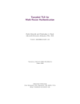
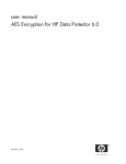
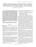
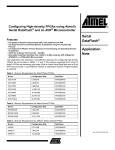
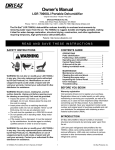
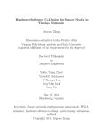
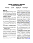
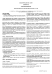
A Combined Hardware and Software Architecture for
Secure Computing
Jörg Platte
Edwin Naroska
Computer Engineering Institute
University of Dortmund
Germany
Computer Engineering Institute
University of Dortmund
Germany
[email protected]
[email protected]
ABSTRACT
1.
Remote code execution becomes more and more important
as can be seen by Grid computing or distributed computing
projects like SETI@home. However, executing programs on
foreign computers leads to security risks if the program contains sensitive data or algorithms. Current operating systems can protect user programs from other malicious programs running on the same host. But this does not prevent
attacks from a system administrator or a malicious operating system. Further, even if the operating system is trusted
it is possible to physically intercept communication between
main memory and processor to gather information about the
executed programs. As a result, these security risks prevent
the execution of sensitive algorithms or programs computing
on sensitive data on not trustworthy remote systems.
In this paper we present a combined hardware and software architecture to provide a secure and tamper resistant
computing environment without relying on trusted system
administrators and a fully trusted operating system. Our
proposed architecture provides a security enhancement implemented on top of a standard processor. Compared to
external co-processor solutions, our architecture does not
suffer from memory, functionality and performance limitations. Furthermore, normal and protected programs can be
run concurrently in a multitasking environment.
In near future, there will be a need for securely executing programs on foreign computers. For example, in a Grid
computing environment, many different computers owned
by Universities or private companies can be connected over
the Internet to dynamically build a supercomputer in order to solve hard scientific problems or performing complex
simulations. The Grid also becomes more and more interesting for companies if they do not have a constant workload to utilize a local simulation cluster. Then, parts of
the available computing power can be rented out to foreign
users. However, most algorithms and/or data are intellectual property of the foreign user and therefore special care
must be taken to protect them. Furthermore, protection of
algorithms and data is not sufficient because any modification of the program flow must be prevented since this may
result in wrong execution results1 . Hence, our proposed architecture changes must achieve two goals:
Categories and Subject Descriptors
C.1 [Processor Architectures]: Miscellaneous;
D.4.6 [Operating Systems]: Security and Protection
General Terms
Security, Design
Keywords
Certified execution, encrypted programs, secure processors
Permission to make digital or hard copies of all or part of this work for
personal or classroom use is granted without fee provided that copies are
not made or distributed for profit or commercial advantage and that copies
bear this notice and the full citation on the first page. To copy otherwise, to
republish, to post on servers or to redistribute to lists, requires prior specific
permission and/or a fee.
CF’05, May 4–6, 2005, Ischia, Italy.
c ACM, (2005). This is the author’s version of the work. It is posted here
°
by permission of ACM for your personal use. Not for redistribution. The
definitive version was published in CF’05, May 4-6, 2005, Ischia, Italy.
http://doi.acm.org/10.1145/1062261.1062308.
INTRODUCTION
1. Protection of program code and data. It should be
impossible for an attacker to get information about
the executed program code and the computed data.
2. Preventing any external modifications during program
execution. The program must be executed in the intended way or aborted immediately.
Unlike a dedicated co-processor to execute secure programs,
we present a processor architecture which allows execution of
both normal unprotected programs and encrypted protected
ones. Therefore, existing programs can easily be secured
without the risk of not being executable due to memory restrictions or major architecture changes, which might occur
in the co-processor case. This allows simple integration into
existing computers, since most software is unencrypted and
can be executed without any changes. However, in this work
we will not present physical modifications required to protect the core of a processor from physical access. Only logical changes to the processor design and the software will be
discussed. The means to establish security include memory
encryption and protection, register protection and a partly
trusted operating system. All these changes provide parallel
execution of trusted and normal programs at the same time.
Further, trusted programs do not suffer from significant limitations.
1
We are assuming that all user programs do not contain any
programming errors resulting in wrong computations.
Figure 1: SPARC Register Windows
LOCAL
OUT
Set 0
Set 0
Set 0
CWP
IN
IN
LOCAL
OUT
IN
Set 2
Set 2
Set 2
Set 0
OUT
IN
LOCAL
OUT
IN
LOCAL
OUT
Set 3
Set 1
Set 1
Set 1
Set 3
Set 3
Set 3
SAVE, TRAP
RESTORE, RETT
In section 2 we are describing the process of loading and
executing a program. The requirements for a secure execution are presented in section 3. Our proposed design is
explained in section 4. Section 5 describes other approaches
to provide a secure computing framework. Sections 6 and
7 are presenting our simulation results and explain future
work.
2. PROCESSOR ARCHITECTURE
This section provides a short overview about the SPARC
architecture [9, 12], which is used as a base for our processor
design. A SPARC processor provides 32 logical registers,
separated into four different register subsets: global, local,
in and out. Each subset contains eight registers. Internally
they are mapped to up to 520 physical registers in up to 32
sets. As you can see in figure 1, the in and out registers of
side by side sets are overlapping to allow parameter passing.
The register mapping is controlled by the current window
pointer (CWP). Executing SAVE instructions or during a
TRAP the window pointer is decremented and incremented
by RESTORE and RETT instructions. A CWP over- or
underflow results in a TRAP which is used to read or write
the current register set from or to the stack.
Like most modern processors, the SPARC architecture
provides a user and a supervisor mode [9]. In user mode
execution of privileged operations and access to sensitive
processor status registers and memory regions is prohibited.
This is used to protect OS resources from modifications by
user programs. To enter the supervisor mode, a TRAP instruction is executed.
The SPARC architecture provides 256 TRAP’s. On each
TRAP a branch into the trap table is performed. This table stores the first four instructions of every corresponding
TRAP handler. At the end of the TRAP function, the OS
returns to the user program by executing a RETT (return
from trap) instruction.
The memory management unit (MMU) allows mapping
between a program dependent memory layout (context) to
the physical memory available. The MMU distinguishes programs by a unique process ID (context ID) and can only be
configured in supervisor mode.
On a multitasking OS like Linux many programs can be
executed in a time-multiplex manner using a scheduler. The
scheduler grants every program a time slot in which the
program can be executed. At the end of the time slot a
timer generated interrupt will invoke a TRAP function to
enter supervisor mode. This TRAP handler will save all
related data like the stack pointer, program counter and the
global and floating point registers of the current program in
a process related memory area and the remaining registers
on the stack. Then the OS can safely change the MMU
context to the other programs memory layout and restore its
register values. Finally, the OS returns to user space using
the RETT instruction to continue execution of the newly
selected program at the previously interrupted position.
3.
REQUIREMENTS FOR SECURE
COMPUTING
In this chapter we want to sum up the requirements for a
secure and tamper resistant execution and present appropriate hardware and software changes. In detail, the following
features must be present to provide a secure environment:
• Algorithm and data protection: To protect the
program code and all sensitive runtime data stored
on the stack or the heap, a transparent encryption of
these parts must be supported. Otherwise, the memory contents may be directly read from memory after
deactivating the processor or sniffed from the memory
bus.
• Identification of the target processor: The target
processor must be identified to prevent execution on a
simulated or modified processor. For example, only the
target processor shall be able to execute the program
code.
• Data and program integrity: Encryption does not
prevent manipulation of encrypted data. Hence, additional integrity checks are required to prevent the
following attacks, which may result in data leakage or
an unintended execution:
– Program instruction manipulations
– Runtime data manipulation
– Replacement of newly written runtime data by
old data (replay attack)
• Proper TRAP handling: Interrupting a trusted
program and restarting it later without the ability
to modify any program related data in the meantime
must be ensured. Hence, the state of the program
must be fully reconstructed after the TRAP in every
case without the possibility to modify program data
in an unauthorized way. This leads to the following
requirements during a TRAP:
– Register protection: Any unauthorized read or
write access to register values must be prevented
since they may contain sensitive data.
– Permission of authorized register access: During a TRAP some register values must be read by
the OS. Examples are parameters of the system
call, the program counter or the stack pointer.
During a register window over- or underflow or
a context switch one or all register sets must be
read or written. Therefore, a mechanism to allow
authorized access to all registers is required.
– Prevention of program counter manipulations: Any manipulation to the program counter
can be used to execute the program in the wrong
order, to skip parts of the program or to crash the
program. Further, vital parts of the program may
be skipped. Hence, any program counter manipulation must be prevented.
– Prevention of unauthorized memory access
by the OS: The OS has full access to the whole
memory area of the program and knows all dynamically requested memory regions and the current position of the stack pointer. Therefore, a
manipulation or examination of memory areas must
be prevented. However, some memory access must
be allowed, since, as described above, the register
values must be stored in memory during a context
switch.
• A partly trusted OS: As we have seen above, the OS
must be able to alter protected program data during a
TRAP in an authorized manner. Therefore, all parts
of the OS which need access to these sensitive data
must be trusted.
Nevertheless we can only provide a protection against
direct program or data manipulation or disclosure. The
OS can return false or forged values during a software
TRAP. Therefore, the user program must check all
values returned by the OS. This can be done using
cryptography for all external data transfers like file or
network access. Additionally, newly allocated memory
regions must be validated, to assure that the memory
resides in a protected area of the virtual address space.
These checks can be done in user space and included
in appropriate library functions.
• Statically linked programs: Dynamically linked programs will be linked during startup or runtime with
shared libraries installed on the actual system. These
libraries are unchecked and may contain malicious program code. As shared library functions are executed in
the context of the program and therefore having access
to all program data, malicious shared libraries may be
used to reveal protected program code or data. As a
result, only statically linked programs are supported
by this architecture.
4. DESIGN
This section describes all design issues in detail. The last
section has given a rough overview about all requirements
and here we want to present all changes needed to realize the
secure computing requirements. At first we want to explain
the hardware modifications and then the software changes.
4.1 Hardware modifications
In this section we describe hardware modifications based
on a SPARC RISC processor. Our goal was to carefully enhance the processor to implement the security enhancements
without major changes to the processor core, the OS and
the userspace program code. Therefore, we avoided direct
changes to the processor where possible and implemented
most additional functionalities as separate additional units.
The units are controlled by a set of new instructions (see
table 1).
Each time, the processor detects an unauthorized access,
the currently running trusted program is terminated immediately and all program related data in the processor is
cleared. This ensures, that a trusted program can only be
Table 1: Important new instructions
Description
Secure TRAP Start
Secure TRAP End
Copy the decrypted secret key k to the
keystore
Decrypt the secret key
DK
Set the virtual memory location of the enRH
crypted root hash
RPROT
Set Register protection mask for the current register set
RUNLOCK Permit write access to all registers
Set the encrypted and protected areas
AS
AG
Get the encrypted and protected areas
TERM
Terminates a secure process and delete k
from the keystore
Name
STS
STE
KC
Figure 2: The modified processor core
Tamper resistant CPU core
Register
Protection
Register Set
AES Unit
Integer Unit
Status Register
Keystore
Cache
RSA Unit
MMU
Unprotected Main Memory
executed successfully if it is not modified. Additionally, a
TRAP is generated to inform the OS, that something went
wrong during execution.
In the following all modifications are described in detail.
Figure 2 gives an overview about the modified design. The
new hardware units are marked with dotted lines.
4.1.1
Cache
The cache is a functional unit which must be a physical
part of the processor core to ensure data protection, since
the cache stores all data unencrypted. This cache provides
two additional functions compared to a normal cache. First,
it can transparently encrypt and decrypt all data read from
main memory. Second, the cache can verify the integrity of
the read cache lines. Both functions are implemented inside
the cache to improve the performance.
4.1.1.1
En-/decryption.
A cache must support a random access to the main memory in cache line size quantities. This requires independent
encryption and decryption of every cache line. Hence, using
a cipher block chaining (CBC) mode for encryption, where
each block must be XORed with the previous one, is not possible. Additionally, to simplify the design, every cache line
must be aligned to 128 bit quantities, which is equal to the
AES block size. We have chosen a cache line size of 512 bits
or four AES blocks (called cache blocks in the following).
To speed up the decryption process, each AES cache block
can be decrypted independently of the other three blocks
Figure 5: Hash tree layout
Figure 3: Hash value computation
Cache Line
Cache Block
Bp1
128 Bit
Cache Block
Bp2
128 Bit
Hash block
Cache Block
Bp4
128 Bit
Cache Block
Bp3
128 Bit
Cache block
Root Hash
XOR
Hash
H
128 Bit
Session Key and Virtual Address (V)
Secret key k
0…..0
V
128 Bit
352 Bit
32 Bit
information about the hashed contents of the cache
line.
Figure 4: Decryption of a cache line
Hash
128 Bit
Memory contents
XOR
Bc1
Bc2
Bc3
Bc4
R1
R2
R3
R4
128 Bit
128 Bit
128 Bit
128 Bit
128 Bit
128 Bit
128 Bit
128 Bit
Fetch
Fetch
Fetch
Fetch
AESk
AESk
AESk
AESk
XOR
XOR
Cache Block
Bp1
128 Bit
Cache Block
Bp2
128 Bit
XOR
XOR
Cache Line
Cache Block
Bp3
128 Bit
Cache Block
Bp4
128 Bit
and the decrypted data can be passed immediately to the
processor. However, the integrity of a cache line can only
be checked after reading all four blocks.
We are using AES with the secret key k (Ek ) in counter
mode. In counter mode, a so called counter value is encrypted and XORed with the plaintext data for encryption.
Typically, the counter value is a value which will be increased for each new encryption. In our case, we are using
the AES hash [1] function2 H to compute a cache line dependant hash value as a base counter. Other secure hash
algorithms like MD5 [10] can be used, too, but we have
chosen AES because our design already contains an AES
encryption unit.
Figure 3 describes the hash value computation. The hash
value is used to check the integrity of the cache line and to
provide a unique counter value. At first, all four plaintext
cache blocks Bp1···4 are XORed with k and the virtual base
address V of the cache line:
• Incorporating the base address V of the cache line is
required, because otherwise, the encrypted cache line
may be copied to another virtual address without detection. Further, the same contents at different addresses are encrypted differently.
• XORing the secret key k into the plaintext is required
to make the hash value computation dependant on k.
Otherwise, the hash value may be exploited to extract
2
Unlike the proposed size of 256 bits, we are using only a
key and block size of 128 bits resulting in a 128 bit hash
value.
The result is then fed to the AES hash function H to compute the hash.
As you can see in figure 4, every cache line consists of
four cache blocks. Hence, one hash value is not sufficient
as a counter, because this would result in the same pattern used for four cache blocks. Therefore, the hash value
is XORed with the four different 128 bit patterns R1···4 to
generate four different counter values. The most time consuming parts, the encryption Ek of the counter value and
the memory fetch, are parallelized to hide the encryption
latency. When both the data and the encrypted counter
values are available, they must only be XORed to get the
decrypted data. Encryption of a plain cache block Bpx and
decryption of a ciphered cache block Bcx are working exactly the same as in both cases the counter value is only
encrypted. As a result, a ciphered cache block will be computed as follows:
Bci = Ek (H(Bp1 ⊕ k|Bp2 |Bp3 |Bp4 ⊕ V ) ⊕ Ri ) ⊕ Bpi for
i = 1, 2, 3, 4, where | denotes a concatenation
4.1.1.2
Data integrity using hash trees.
Data integrity cannot be ensured using the modified hash
approach described above, because it cannot prevent replay
attacks. Therefore, we have implemented the hash tree
model described in [4]. In this model, all hash values are
stored in a separate virtual memory area. Since a hash value
consists of 128 bit and a cache line is 512 bits long, we can
store up to four hash values in a cache line. As you can see
in figure 5, each hash line (=a cache line storing only hash
values) must be protected by another hash value. At the
end the last four hash lines are protected by a root hash.
This root hash must be stored permanently in the processor
using the RH instruction at the beginning of the program
execution to prevent further manipulations. Therefore, only
the processor can transparently update all hash values including the root hash based on data changes in the protected
memory. To prevent manipulations of the executable, only
the root hash must be stored encrypted in the executable.
All other hash values for static data are stored unencrypted.
This concept provides maximum security and reduces the
number of hash comparisons, since already checked hash
lines in the cache are always trustworthy and hash line comparisons must only be taken up to the first verified hash
line found in the cache. Hash values of currently unused
memory areas are set to zero. This reduces the size of the
executable dramatically, since only used hash values must
be saved. The OS can transparently map pages filled with
zeros to the unused parts.
The current context ID in conjunction with the trust level
of the currently executed instruction changes the way data
can be accessed. Data decryption is only performed for
trusted program code executed with the correct context ID.
In every other case, the encrypted data is passed to the
processor. Already decrypted cache blocks are invalidated
to encrypt them and reread them encrypted, if an untrusted
instruction tries to access them. If encrypted parts are modified by untrusted instructions, the corresponding hash values are not updated. This results in an immediate process
termination, if the trusted process accesses them.
Operating
System
Hash Tree
DMA
Parameter
passing
00000000
RSA Unit
The RSA Unit is required to proof the origin of the processor by encrypting the secret key k of the secure program
to be executed with the processors public key kpub . The
integrity of kpub can be checked by comparing it with the
manufacturer-signed key of the target processor. This guarantees successful decryption only by the selected processor,
because the corresponding private key kpriv is stored in the
RSA unit and cannot be read by a program. The decrypted
secret key k must then be stored in the internal keystore by
using the KC instruction. Therefore, it is impossible for the
OS to read k in cleartext.
4.1.3
Executable
Register protection
Register protection is a major part of this security architecture. In our design the current context ID is stored with
every written register value.
Every read or write access to a protected register by an
untrusted instruction terminates the currently running program. Likewise, a read access to a register not written by
the currently running protected program terminates the protected program. To allow parameter passing between the OS
and the program, register protection can be partly deactivated using the RPROT instruction. It is executed in a
trusted environment and allows to set a mask to unprotect
matching registers in the current register window. Already
protected registers cannot be unlocked using RPROT, because protection is only disabled for the next register write
access, but unlocked registers can be read without program
termination. Any change of the the register window pointer
deletes the mask set by RPROT.
However, some OS TRAP routines must have access to
all register values. For example, during a context switch, all
register contents must be stored on the stack by the OS. Ad-
Unprotected Area
4.1.2
Protected Heap
Encrypted Area
Memory requirements.
Due to the hash values used to decrypt and verify the
memory contents memory demands are increased. The first
level of hash lines (the hash values printed on top of the
cache blocks in figure 5) consumes additional 25 % memory
of the original memory size. These hash values are required
both for the program code and volatile encrypted data. The
other levels up to the root hash are only required to protect
volatile data, because replay attacks are only possible on
this kind of data.
Programs which generate instructions on the fly can be
used with this design, too, but then replay attacks may be
possible. This can be avoided by using a modified design
which provides a special area for static program code. All
other program code can then be verified using the complete
hash tree. The additional overall memory penalty for the
hash values can therefore vary between 25 % (only static
program code) and 33 % (only volatile data).
Protected Area
Protected Stack
Unprotected
Area
4.1.1.3
Figure 6: Memory Layout
FFFFFFFF
ditionally, during a register window over- or underflow, some
register values must be saved or restored. Our architecture
permits full access, if the corresponding TRAP instructions
accessing them are trusted. This results in TRAP’s which
must be executed in an fully trusted environment.
Additionally, another instruction for permitting write access to protected registers is needed, since during a context
switch the register values must be overwritten with the values of the new context.
4.1.4
Speculative execution
Checking the data integrity is a very time consuming task.
Hence, it is desirable to execute most instructions speculatively while checking. This improves the performance, but
leads to problems, if the instructions are tampered, since execution of this kind of instructions must be prevented. The
processor will terminate an already running program immediately after detecting a tampering attempt. Therefore,
instructions can be executed speculatively until a TRAP is
executed. In case of a TRAP, the processor waits until all
read data are checked and then starts executing the TRAP.
Hence, modified instructions or data are detected at least
before the next system call or context switch is executed.
4.1.5
Memory layout
The cache must be able to distinguish between normal,
protected and encrypted memory. In our design we are using
a relatively fixed layout to simplify hardware implementation. Figure 6 shows a valid per process memory layout for
a linux system. To execute protected programs, at least four
different and partly overlapping virtual memory areas must
be provided. The biggest area is used for protected data
and each cache line in this area is protected by a hash value.
The trusted part of the OS must be in the upper part of
this area. Inside this area a second area of encrypted memory can be specified. Each read or write access in this area
leads to a transparent de- or encryption and an update of
the corresponding hash entries. This area is dedicated for
the program code, stack and the heap. The remaining parts
of the memory, including the hash values are unencrypted
and unprotected and can therefore be used for DMA access, parameter passing (between the OS and the program)
and shared memory. The memory layout must be passed to
the cache using the AS instruction and cannot be modified
during runtime of the whole program.
4.1.6
Virtual memory
The cache must operate on virtual addresses, as they are
needed for encryption decryption and for the hash line address calculation. This results in an additional data path
between the cache and the MMU to query virtual addresses.
To speed this up, the cache can store physical and virtual
addresses for each cache line. Then, the cache can compute
the required hash line address internally and if the computed
hash line is in the cache, no MMU query is needed.
Virtual memory provides the ability to move currently
unused parts of a program on the hard disk and reread this
memory on demand. Because of this, the operating system
must ensure the availability of all required hash values in
physical memory. For example, if one page containing hash
values is not found, the cache cannot continue checking the
integrity or writing dirty protected blocks back to memory.
As a solution, we are disallowing removal of pages containing
hash values required to check other hash values or cache
blocks still located in physical memory. They can only be
removed, if the corresponding memory regions protected by
these hash values are also removed.
4.2 Software changes
Due to the new instructions, the cryptography units and
the memory layout, software modifications in the OS and
the executed program are required. At first, we will describe
the required modifications in the OS and then the changes
to the executable.
4.2.1
Operating System changes
The first major change in the OS is required due to the
new memory layout.
4.2.1.1
Memory Layout.
A small trusted part of the OS is located in protected
memory. These instructions must remain static during the
whole runtime of the OS, because every trusted program
must provide matching hash values. This memory area is
used to store TRAP table and parts of the TRAP routines.
The virtual memory management of the OS must be adjusted to consider the hash tree layout. During a page fault
not only the page with the requested data but also all pages
needed to validate this cache line must be loaded. This increases the latency, before the interrupted program can be
restarted. Furthermore, pages containing hash values cannot be swapped to disk, while the memory regions protected
by these pages are still in memory.
4.2.1.2
TRAP’s.
The TRAP table and the first and last parts of the TRAP
routines must provide additional instructions to guarantee
unmodified execution of a program. At the beginning of
every TRAP, which may execute unprotected instructions,
the current TRAP number and the frame pointer is stored
at a special protected memory area unique for every program. Then, the normal unprotected TRAP routines can
be executed after executing the special instruction STE. It
ends the protected part of the TRAP routine. As a RETT
instruction of an encrypted program can only be executed
from trusted memory, every TRAP must jump to the corresponding end of its TRAP routine located in this trusted
memory area. There, the secure TRAP mode must be reenabled using the special instruction STS. Then, the previously stored TRAP number and the previously stored frame
pointer can be compared with the current ones and on a
match the OS can safely return to the program.
Storing of the frame pointer ensures, that the current register set is valid. An invalid register set cannot be detected
by register protection, if the registers in the wrong set are
written by the trusted program, but in another recursion
level. But if the stored stack pointer matches the one in the
current register set and the register value can be read, the
current register set is valid.
The STE and STS instructions are required to ensure the
whole execution of the last part of the TRAP routine. Otherwise, a malicious OS may jump directly to the RETT instruction without checking the TRAP number and the frame
pointer. In our design this is impossible, because the RETT
instruction can only be executed in TRAP mode which can
only be re-enabled by the STS instruction.
The OS must be able to execute trusted and normal programs simultaneously. The additional checks during a TRAP
are useless for normal programs. As a result, the OS should
provide two TRAP tables. One for normal and one for protected programs. The SPARC architecture supports this
with a TRAP-table base register. This register must be
updated during a context switch to reflect the type of the
program to run.
4.2.1.3
Program loader.
The program loader must be enhanced to detect protected
programs and start them in a protected environment. The
largest part of the program loader is located in unprotected
memory, because it must operate before any program providing hash values is loaded. After detecting an encrypted
program, the encrypted secret key k must be read and passed
to the RSA unit for decryption. In the meantime, the OS
maps the program parts (the program code, hash values,
data) to their destination in the virtual memory address
space. Then, the memory layout must be passed to the
cache using the AS -instruction. This instruction can only
be used before k has been stored in the keystore to prevent
subsequent manipulations by modifying the protected areas
during runtime.
After decrypting k, the OS can pass it to the cache using
the KC instruction. Then, the position of the root hash is
passed to the cache using the RH instruction. For simplicity,
it is stored in a separate encrypted cache line to allow the
cache to decrypt it using the standard decryption hardware.
The root hash is then permanently stored in the cache and
the program loader exits and starts the actual program.
4.2.2
Program changes
The architecture requires small user space changes. Fortunately, most of them can be be implemented by modifying
low level libraries and therefore they are mostly invisible to
programmers. For example, the libc must be modified to
un-protect registers before a system call using the RPROT
instruction and memory regions containing parameters must
be allocated in unprotected memory parts (see figure 6).
At startup, a protected program must check the memory
regions for protected and encrypted memory. They are set
at program startup by the program loader using the special
instruction AG. During runtime, the regions cannot be modified, but the program loader may initialize them wrongly.
Therefore, the secure program checks them.
Unfortunately, the OS may return arbitrary addresses for
a malloc call and therefore, each returned virtual address
must be verified. Otherwise, the OS may return memory in
unencrypted regions. Fortunately, this check can be transparently done in the libc, too.
The only major change from the programmers point of
view is the handling of dynamically requested memory. Now,
the programmer may request either encrypted, protected or
unprotected memory which results in an extended system
call to specify the memory type. The default memory type
is encrypted/protected memory. Hence, only programs or libraries requesting memory for parameter passing to the OS
must be changed to explicitly request unprotected memory.
All other libraries can remain unchanged.
As a result, a wide range of programs can be compiled for
our architecture without, or only with slightly changes in
the memory handling. This significantly simplifies program
development.
4.2.2.1
Compiler changes.
A modified instruction set require changes in the compiler
suite. Fortunately, all new instructions are used in low level
parts of the OS and the libraries, which are mostly written
in assembler. Hence, only the assembler part must be enhanced to support these instructions. Other parts, like the
encryption and the computation of the hash values, must
be done after statically linking the program. They can be
implemented using a postprocessor and require no modifications to the existing toolchain.
5. RELATED WORK
Using cryptography to protect algorithms and data in a
tamper resistant environment is not a new approach. Secure
co-processors have been proposed which provide a tampersensing and tamper responding secure environment. These
processors can be implemented on smart cards (for example,
[7]) or as a co-processor shown by [14] in a PC (for example,
the IBM 4758 [2]). These co-processors provide a secure environment. But they are limited in terms of processor speed
and memory and often, programs must be significantly modified to be suitable to this kind of co-processors. Therefore,
they do not provide an easy to use and expandable secure
environment.
A more related approach to ensure a secure execution of
programs are the eXecute Only Memory (XOM) architecture [6] and its successor, the AEGIS [11] architecture. Both
architectures provide transparent program and memory encryption using an enhanced standard processor. Protected
parts begin with a special instruction and all further instructions are encrypted. Unfortunately, only small parts
of a program can be encrypted, because both architectures
do not allow system calls while in encrypted mode. Only
normal interrupts are allowed and the processors hardware
ensures register and program counter protection by saving
them in encrypted memory and clearing all register contents.
This prevents any parameter passing to the operating system and allows process restarting only at the interrupted
position.
Further, this design also complicates the encryption of
large algorithms, because many parts of an algorithm typically rely on additional library functions and these library
functions must be split into secure parts and parts requiring system calls, for example by calling malloc functions.
Hence, all libraries, not only low level ones, must be revised
and modified. As a result, protected algorithms can only
easily implemented for small algorithms. In contrast to the
AEGIS design, our design can protect the whole program
including additional libraries.
The AEGIS architecture provides status changes during
an interrupt and guarantees correct restauration. But an
AEGIS program contains unprotected parts used for system calls. During execution of this parts, a malicious OS
can alter the program counter or modify register values and
therefore, the unmodified execution of a whole program with
encrypted and unencrypted parts cannot be guaranteed. As
a result, only sensitive algorithms can be protected, but not
the whole program.
In AEGIS, memory protection is done by encrypting the
memory contents with AES [8] and protecting them by hash
values. Like our approach, both encrypted and normal programs can be executed in a multitasking environment. But
encryption is done by encrypting the data directly. This increases the decryption latency, because the data must first
be read and can then be decrypted. In our design, encryption and fetching data can be done simultaneously and the
fetched data must only be XORed with the encrypted hash
value. As we can see in section 6, this hides the decryption latency very effectively. On the other hand, writing
encrypted data is slower in our case, since the hash value
must be computed first. The AEGIS architecture can start
encrypting the data directly after selecting a random initialization vector. But fortunately, this additional latency
caused by our architecture can be hidden by providing a
longer write queue. For most programs the read latency is
more important, since a program can only be continued after
providing the requested data.
Another advantage of our design is is the amount of memory required to encrypt and validate the memory. We must
only store the counter value, which can be used as a hash
value to validate the integrity of the cache line and as a
counter value to decrypt the cache line. Therefore, only one
additional read access is required to encrypt and check the
contents of a cache block. In the AEGIS architecture the
hash and an initialization vector must be stored.
AEGIS provides register protection in hardware by storing
all registers in encrypted memory and clearing the registers
during an interrupt. In a multitasking system our approach
is much faster, particularly with a huge register set. Register
values are protected, too, but are stored in memory only on
demand during a context switch or a register window overor underflow. For example, a short TRAP, which needs only
the current register set, does not result in storing all registers
in memory.
Other approaches to provide a trusted environment, like
TCPA [13] can provide only a trusted software platform.
Hardware attacks, like sniffing on busses, are still possible.
Additionally, compared to our design larger parts of the operating system must be trusted which increases the possibility of exploitable errors in these parts. Therefore, mostly
software based systems do not provide the same protection
level as our architecture.
6. SIMULATION RESULTS
Table 2: Size of the new hardware units
Slices LUT
Part
LEON2 (unmodified)
3837
6972
10016
LEON2 (modified, without RSA 7073
and AES units and cache)
AES unit
823
5207
RSA unit
14562 26533
Currently, we have implemented and tested parts of the
architecture in hardware and software. The basis of our
hardware modifications is the LEON processor [3], a freely
available SPARC compatible VHDL model. LEON provides
a fully featured SPARC V8 processor including a 5-stage
integer unit, L1 cache, MMU and memory interface. We
have synthesized the VHDL code for a Virtex II XC2V4000
FPGA to measure the size requirements of the changes.
Our modifications are mostly implemented in external
units to simplify the design process. Hence, we did not
modify the original L1 cache, but we added an additional
L2 cache which implements all the encryption and decryption parts. The MMU was modified to pass the physical
and virtual address along with every data access to the L2
cache. The usage of a L2 cache with an unmodified L1 cache
requires to flush the L1 cache at every TRAP, since the L1
cache provides no extended access control. We have implemented the new instructions in an additional pipeline stage
in the MMU to have direct access to the L2 cache.
The cache has direct access to a AES encryption unit.
Due to the usage of the AES counter mode, we do not need
a decryption unit, since the counter value is encrypted only
in every case. This simplifies the design of the AES unit and
saves space. We are currently using eight single AES units3
in total to speed up encryption of the four counter values
for each cache line.
By using AES in counter mode, the decryption latency can
be fully hidden compared to the AEGIS [11] implementation, where the cache block contents are directly encrypted.
In [5] an AES counter mode hardware design is presented,
which has an encryption latency less than the transmission
latency for 512 bits of a typical DDR400 SDRAM module.
Therefore, with this AES module, the data can be decrypted
on the fly without further delay after reading the whole
cache line. The only additional delay is caused by reading
the corresponding hash value for the cache line.
The LEON core implements 136 registers in 8 sets. In our
architecture, for each register value the current 8 bit context
ID is stored. This ID is evaluated internally and cannot be
3
four for read access and four for write access
read or written by software. This consumes 1088 bits extra
register memory. However, it can be reduced by limiting the
number of simultaneous encrypted processes and assigning
only lower ID’s to protected programs.
The RSA unit is implemented as a separate part of the
processor with its own clock signal and programmed by a
separate interrupt driven interface. This makes this unit
independent from the other design regarding to the main
clock and timing constraints, because it typically operates
at slow clock rates compared to the rest of the processor.
This does not affect the performance of the whole processor
significantly, since this unit is only needed during the start of
a program and the processor can execute other instructions
during RSA decryption.
As we can see in table 2, the RSA unit needs more than
two times more slices than the modified LEON core. This
is due to the LEON2 design, which was chosen to provide a
small processor implementation without additional complex
units like branch prediction, speculative execution or dynamic scheduling. The cache will consume the largest part
of the processor design, as it must be as large as possible to
speed up decryption and integrity checks. As a result, the
logical changes to the processor design, like register protection, new instructions and speculative execution of protected
instructions, are small compared to the required additional
cryptography units.
7.
CONCLUSION AND FUTURE WORK
In this paper we presented an architecture, which permits concurrent execution of unprotected as well as protected/encrypted programs on the same processor. Our
architecture can protect programs from program code and
data manipulations and program flow manipulations. Data
is encrypted using AES in counter mode with a 128 bit key.
The counter value is additionally used as a hash value to
detect all external modifications. This saves memory and
requires only one additional memory access to decrypt a
cache line. To prevent replay attacks, all counter values
except those values used for static program code, are additionally protected by hash values resulting in a hash tree. In
our design, integrity checks and data decryption are transparently implemented in the cache.
Besides memory encryption, the register set must be protected, too. Our architecture implements a register protection, which grants access to register values only for trusted
instructions. Unauthorized register access is treated like a
manipulation attempt and results, like any other detected
manipulation, in the immediate termination of the protected
program.
One design goal was to allow system calls for protected
programs in order to to minimize the required changes from
a programmers point of view. Therefore, parts of the operating system must be trusted to allow parameter passing in
registers or memory. We tried to minimize the trusted parts
of the OS by requiring trust only for low level parts in the
TRAP handling. All other parts of the OS can remain untrusted. Each protected program establishes trust to these
parts of the OS by providing matching hash values for these
parts.
These combination of extended hardware protection in
conjunction with the trusted parts of the OS can prevent
all manipulations by external attackers (like manipulations
in external memory). Internal attacks by the administra-
tor or the OS are prevented, too, because modifications in
trusted parts and access to protected memory regions or registers by untrusted parts will be detected and prevented by
the hardware.
All protected programs can be written without major changes compared to unprotected programs and all program code
and volatile data is protected by default. Most of the required user space changes can be implemented transparently
in low level libraries. Therefore, only minor changes in the
compiler suite are required.
As far as we know this is the first architecture that provides an integrated secure environment, which can protect
a program during the whole execution. This is achieved
by preventing data, instruction and program flow manipulations with additional encryption. As a result, the intellectual property of algorithms and data is protected. Unlike
secure co-processors, our design can easily be enhanced in
terms of memory and processing power like any other unprotected design.
Compared to the AEGIS design, our architecture provides
a faster memory decryption and less memory overhead for
the hash values. Additionally, with our system the whole
program can be encrypted by providing system calls for secure programs and not only small parts of the program. This
significantly simplifies secure program creation.
Since our design requires changes in the operating system,
full tests with modified hardware and a modifies OS are
required to get an overview about the additional latencies
triggered by our design. This will be done in the future.
8. REFERENCES
[1] B. Cohen. AES-hash.
http://csrc.nist.gov/CryptoToolkit/modes/proposedmodes/aes-hash/aeshash.pdf, May
2001.
[2] I. Cryptographic Products. IBM PCI Cryptographic
Coprocessor: General Information Manual, May 2002.
[3] J. Gaisler. LEON2 Processor User’s Manual - XST
Edition (Version 1.0.24). Gaisler Research,
http://www.gaisler.com/doc/leon2-1.0.24-xst.pdf,
2003.
[4] B. Gassend, D. Clarke, G. E. Suh, M. van Dijk, and
S. Devadas. Caches and Hash Trees for Efficient
Memory Integrity Verification. In Proceedings of the
Ninth International Symposium on High Performance
Computer Architecture (HPCA-9), Feburary 2003.
[5] A. Hodjat and I. Verbauwhede. Speed-area trade-off
for 10 to 100 Gbits/s throughput AES processor. In
2003 IEEE Asilomar Conference on Signals, Systems,
and Computers, November 2003.
[6] D. Lie, C. A. Thekkath, M. Mitchell, P. Lincoln,
D. Boneh, J. C. Mitchell, and M. Horowitz.
Architectural support for copy and tamper resistant
software, 2000.
[7] S. Microsystems. Java card security white paper.
http://java.sun.com/products/javacard/JavaCardSecurityWhitePaper.pdf, October
2001.
[8] NIST. Specification for the Advanced Encryption
Standard (AES) - Federal Information Processing
Standards Publication 197. National Institute of
Standards and Technology,
http://csrc.nist.gov/publications/fips/fips197/fips197.pdf,
2001.
[9] R. P. Paul. SPARC Architecture Assemply Language
Programming, & C. Prentice-Hall, Inc, 1994.
[10] R. Rivest. RFC 1321: The MD5 message-digest
algorithm, Apr. 1992. Status: INFORMATIONAL.
[11] G. E. Suh, D. Clarke, B. Gassend, M. van Dijk, and
S. Devadas. AEGIS: architecture for tamper-evident
and tamper-resistant processing. In Proceedings of the
17th annual international conference on
Supercomputing, pages 160–171. ACM Press, 2003.
[12] SUN. The SPARC Architecture Manual, version 8.
SUN Microsystems, http://www.sparc.com, 1992.
[13] TCG. Trusted computing group.
http://www.trustedcomputing.org.
[14] B. Yee. Using secure coprocessors. PhD thesis,
Carnegie Mellon University, May 1994.