1
Configuring High-density FPGAs using Atmel’s
Serial DataFlash® and an AVR® Microcontroller
Features
• Completely In-System Programmable (ISP), both DataFlash and AVR
• Use HyperTerminal to Download Binaries to DataFlash using the XmodemCRC
Serial
DataFlash®
Protocol
• Use Optional XY-Modem Terminal Emulator for Downloading and Uploading Binaries
to DataFlash
• ASCII Hex to Binary File Converter – Hex2Bin
• Auto-detect DataFlash Densities from 1-Mbit to 32-Mbit using the AVR ATMega163,
AT90S8515, or AT90LS4433 Microcontroller
Application
Note
This application note describes a cost-effective approach for configuring high-density
FPGAs. As can be seen in Tables 1, 2, and 3, the memory requirements for some of
today’s FPGAs are becoming quite large. With an Atmel Serial DataFlash and an 8-bit
AVR microcontroller, a cost-effective method of obtaining In-System Programmability
is achieved.
Table 1. Memory Requirements for Xilinx®/Atmel FPGAs
Device
Configuration Bits
DataFlash
XC2V1500
5,166,240
AT45DB081B
XC2V2000
6,808,352
AT45DB081B
XC2V3000
9,589,408
AT45DB161B
XC2V4000
14,220,192
AT45DB161B
XC2V6000
19,752,096
AT45DB321B
XC2V8000
26,185,120
AT45DB321B
XC2V10000
33,519,264
AT45DB321B
Table 2. Memory Requirements for Altera®/Atmel FPGAs
Device
Configuration Bits
DataFlash
EP20K600E
5,654,000
AT45DB081B
EP20K1000E
8,938,000
AT45DB161B
EP20K1500E
12,011,000
AT45DB161B
Table 3. Memory Requirements for ORCA® Series 4/Atmel FPGAs
Device
Configuration Bits
DataFlash
OR4E6
4,737,288
AT45DB081B
OR4E10
7,642,376
AT45DB081B
OR4E14
10,332,680
AT45DB161B
Rev. 3301A–DFLSH–4/03
1
Block Diagram
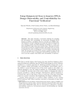
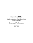
A block diagram of the proposed solution is displayed in Figure 1. An RS-232 transceiver is used to communicate with the host for binary file downloading and uploading.
Communicating with the DataFlash is accomplished with the SPI peripheral on the AVR
microcontroller. A general-purpose I/O on the microcontroller is used as the interface to
the FPGA. Proof of concept was carried out using an Atmel ATSTK500 AVR Microcontroller Starter Kit, which contains everything in Figure 1 except the FPGA, and an Insight
Electronics/Xilinx Spartan® II Demo Board containing a XC2S100 FPGA. The 5 signals
representing the AVR-to-FPGA interface were wire-wrapped. Users should refer to the
ATSTK500 User Guide for instructions on how to correctly set up the board for 3.3V
operation, connect the DataFlash device and enable the spare RS-232 port. Users
should also verify Slave Serial Configuration mode is set up properly on the Spartan II
Demo Board by referring to the Spartan II Demo Board user manual. With the starter kit,
all actions are initiated by pressing one of the switches. Slave Serial Configuration is
accomplished by bit banging the clock and data on the general-purpose I/O pins of the
AVR microcontroller to the slaved FPGA.
See the following link for Spartan II Demo Board modifications to support Slave Serial
Configuration:
http://www.insight-electronics.com/solutions/kits/xilinx/spartan-ii.html
Figure 1. Slave Serial Configuration
AVR
RS-232
Transceiver
TXD
UART
RXD
FPGA
PROG
MOSI
SCLK
SPI
2
MISO
I/O PORT
CS
DataFlash
1-Mbit
to
32-Mbit
CCLK
DIN
DONE
INIT
DataFlash: Configuring High-density FPGAs
3301A–DFLSH–4/03
DataFlash: Configuring High-density FPGAs
Table 4 lists the desired feature and microcontroller required to performing that function.
As an example, if all you want to do is boot the FPGA then the AT90LS4433 is adequate
for the given task, this assumes of course the DataFlash is either pre-programmed or
programmed by a bed of nails. All microcontrollers listed are 3.3V devices that operate
down to 2.7V. Industrial temperature devices are also available. The X in the part number suffix is a placeholder for package type.
Table 4. List of AVR Microcontrollers that Perform a Required Function
Configure the
FPGA
ISP with
XmodemCRC
Receive
ISP with
XY-Modem Send
and Receive
AT90LS4433-4XC
Yes
No
No
AT90S8515-4XC
Yes
Yes
Yes
AT90S8535-4XC
Yes
Yes
Yes
ATMEGA163L-4XC
Yes
Yes
Yes
ATMEGA103L-4XC
Yes
Yes
Yes
Device
The embedded code for this application note was written and tested with ATmega163L,
AT90S8515, and AT90LS4433 microcontrollers. Complete projects for use with
CodeVision AVR Integrated Development Environment are available. Configuration time
from power-up using a 3.69 MHz oscillator is 10.32 seconds in Slave Serial mode and
6.88 seconds in Slave Parallel mode for a Xilinx Spartan II XC2S100 bitstream. Slave
Parallel mode is simulated by writing to external data space on an AT90S8515 instead
of bit banging. An ATICE200 In-Circuit Emulator is used to time the configuration
process.
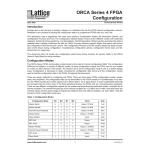
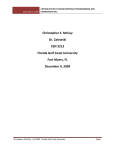
DataFlash is a serial, Non-volatile Memory (NVM) storage solution utilizing small pages
of non-volatile memory. DataFlash devices have SRAM buffers on-chip that are used for
data management. The size of the SRAM buffer is equivalent to the size of the NVM
page in the device. See Figure 2 for a block diagram of a typical DataFlash device.
Table 5 lists the different DataFlash devices available and the page size and number of
SRAM buffers in each device.
Figure 2. Typical DataFlash Block Diagram
FLASH MEMORY ARRAY
WP
RDY/BUSY
RESET
PAGE
BUFFER 1
BUFFER 2
SCK
CS
I/O INTERFACE
VCC
GND
SI
SO
3
3301A–DFLSH–4/03
Table 5. DataFlash Devices Available
Device
Connection between
Starter Kits
Page Size
SRAM Buffers
AT45DB011B
264
1
AT45DB021B
264
2
AT45DB041B
264
2
AT45DB081B
264
2
AT45DB161B
528
2
AT45DB321B
528
2
AT45DB642B
1056
2
Table 6 lists the connector assignments between the two starter kits. If the user
wishes to duplicate this setup, make sure a common ground is connected between the
starter kits.
Table 6. Connector Assignments
Starter Kit
Pin Name
Required File
Formats
ATSTK500
Spartan II Demo Board
INIT
PORTD – Pin 6
JP6 – Pin 16
PROG
PORTD – Pin 5
JP6 – Pin 14
DIN
PORTD – Pin 4
JP6 – Pin 12
DONE
PORTD – Pin 3
JP6 – Pin 10
CCLK
PORTD – Pin 2
JP6 – Pin 8
The embedded source code running on the AVR requires a flat binary image of the bitstream to be located in the DataFlash device. The output of Xilinx’s Promgen program
can be made to produce a flat ASCII hex file representing the contents of the bitstream.
The following commands are used to convert the output of BitGen to a proper flat ASCII
hex file.
Promgen -p hex -b -u 0 counterss.bit
-p hex
specifies hex file output
-b
specifies no byte swapping (byte swapping is used
for prom programmers)
-u 0
specifies up counting from address 0
counterss.bit
input bitstream file from BitGen
It is important to note that the BitGen tool needs to create a bitstream for Slave Serial
mode.
The output of Promgen is counterss.hex
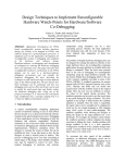
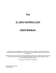
The application XY-Modem contains an ASCII hex to binary file converter. Figure 3
depicts a screenshot of the File Convert Dialog box.
4
DataFlash: Configuring High-density FPGAs
3301A–DFLSH–4/03
DataFlash: Configuring High-density FPGAs
Figure 3. File Convert Dialog Box
By clicking on the open file icons, input and output files can be specified. Once files
have been entered click on the Convert button to convert to a binary file format.
After converting from ASCII hex to binary, the user can either use HyperTerminal or
XY-Modem for downloading to the DataFlash device.
Transport Protocol
for In-System
Programming
XmodemCRC or XY-Modem was selected because of its small-embedded footprint.
Since XmodemCRC uses a 128-byte data packet, it doesn’t impact the AVR microcontroller SRAM memory requirements greatly. At the very end of file transmission, the
packets are padded with the hex value 0xFF. As a result of this padding scheme one
can never tell were the end of the file is. So to determine that the FPGA is configured
properly and to indicate when the AVR should stop reading from the DataFlash, the user
must use the DONE pin on the FPGA as is performed in the ConfigureFPGA_xmodem
routine.
There is no file size information transmitted by the XmodemCRC protocol. Alternatively,
the Ymodem protocol could have been used as the transport mechanism. The Ymodem
protocol does embed file attributes in the first packet transmitted from host to target.
One of these attributes is the file size in bytes. Having file size information makes for a
more robust configuration scheme. For example, if the DONE pin is high before the end
of a file read, or the number of bytes read from the DataFlash device is equal to the file
size in bytes and the DONE pin is low, then there is a problem which warrants further
investigation. Also, if Ymodem was selected then the buffer requirements for the AVR
would have been increased from the XmodemCRC protocol 128-byte packets to
1024-byte packets.
5
3301A–DFLSH–4/03
So XY-Modem was written to take advantage of the small packet size of XmodemCRC
with the file attribute information that Ymodem transmits in the first packet. XY-Modem
transmits the file size information in the first packet just like Ymodem, but only uses
128-byte data packets, reducing the SRAM memory requirements of the embedded
AVR microcontroller to a manageable level. Because file size information is stored in the
DataFlash, the capability to upload a file was added to the XY-Modem program to help
the user verify the contents of the DataFlash device after download.
File size and the DONE pin on the FPGA are both used to determine the completion of
the FPGA configuration cycle in the ConfigureFPGA_xymodem routine.
There are two methods for configuring the FPGA. The proper selection of either of the
two is coupled to the download method used. If XmodemCRC is used to store the binary
bitstream in the DataFlash device then ConfigureFPGA_xmodem should be used to
boot the FPGA. If XY-Modem is used to store the binary bitstream in the DataFlash
device then ConfigureFPGA_xymodem should be used to boot the FPGA.
File size information is stored in page address 0 of the DataFlash. The actual bitstream
data starts at page address 1. Since the smallest page size of any DataFlash device is
264 bytes and the XY-Modem packet size is 128 bytes there is some unused memory in
the first page. This only applies if XY-Modem is used. If XmodemCRC is used, no file
size information is present so the bitstream data is stored starting at page address 0.
The routine that actually configures the FPGA needs to know where the beginning of the
raw data starts.
If XY-Modem is used and the user is configuring an XC2V10000, the AT45DB321-XX
has adequate storage capacity for the binary bitstream and the additional storage
requirements of the file attributes.
Embedded Source
Code
Source code was compiled using the CodeVision AVR Integrated Development Environment. The Main routine is listed below.
void main(void)
{
unsigned char mode;
// low level hardware initialization
__low_level_init();
// dataflash auto detect device density
GetDeviceDensity();
#asm
sei ; /* enable interrupts */
#endasm
do
{
// read mode pins
mode = PINA;
// turn on the correct LED’s
PORTC = mode;
6
DataFlash: Configuring High-density FPGAs
3301A–DFLSH–4/03
DataFlash: Configuring High-density FPGAs
// 20 ms delay ... debounce
ProgramDelay();
switch (mode) {
case (MD_X_RECEIVE) :
recvfile_xmodem(&buf[0]);
break;
case (MD_XY_SEND) :
sendfile_xymodem(&buf[0]);
break;
case (MD_XY_RECEIVE) :
recvfile_xymodem(&buf[0]);
break;
case (MD_CONFIGURE_X) :
if (!fpga_done)
ConfigureFPGA_xmodem(&buf[0]);
break;
case (MD_CONFIGURE_XY) :
if (!fpga_done)
ConfigureFPGA_xymodem(&buf[0]);
break;
}
} while (1);
} // main
On power-up, the hardware is initialized by _low_level_init. GetDeviceDensity is called
next to see which DataFlash device is connected to the SPI peripheral. Interrupts are
enabled and then the main do-while loop starts. Mode is assigned and the value of the
pins on PINA and the LEDs are updated to reflect that. The switches are connected to
PORTA of the AVR through one of the supplied 10 jumper cables as shown in Table 7.
Table 7. Switch Connections and Activated Routines
Switch
Port A Pins
Routine Called when Pressed
Sw0
0
Recvfile_xmodem
Sw1
1
Sendfile_xymodem
Sw2
2
Recvfile_xymodem
Sw3
3
ConfigureFPGA_xmodem
Sw4
4
ConfigureFPGA_xymodem
Sw5
5
Reserved
Sw6
6
Reserved
Sw7
7
Reserved
7
3301A–DFLSH–4/03
The LEDs are connected to PORTC of the AVR through another one of the supplied 10
jumper cables. When the user depresses a pin, the main switch statement initiates an
action, and the corresponding LED is illuminated to indicate the routine is active as
shown in Table 8.
Table 8. LEDs Connection and Activated Routines
XY-Modem
Screenshots
LEDs
Port C Pins
Routine Active when Illuminated
LED0
0
Recvfile_xmodem
LED1
1
Sendfile_xymodem
LED2
2
Recvfile_xymodem
LED3
3
ConfigureFPGA_xmodem
LED4
4
ConfigureFPGA_xymodem
LED5
5
Reserved
LED6
6
Reserved
LED7
7
Reserved
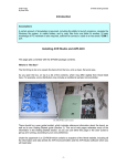
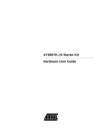
Figure 4 lists the Configure Communication Port dialog box. 8-bit data is assumed.
When you click on the “OK” button, an “ini” file called xymodem.ini containing the new
settings is stored in the install path. The default configuration is shown in Figure 4.
Figure 4. Configure Communication Port Dialog Box
8
DataFlash: Configuring High-density FPGAs
3301A–DFLSH–4/03
DataFlash: Configuring High-density FPGAs
Figure 5 depicts the Send File dialog box. Clicking on the open file icon allows you to
browse the desktop. Once a path or a filename is selected for transmission click on the
“Send” button. Make sure the AVR is in XY-Modem receive mode.
Figure 5. Send File Dialog Box
Figure 6 depicts the Receive File dialog box. Clicking on the open file icon allows you to
browse the desktop. Once a path or filename is selected for reception click on the
“Receive” button. Make sure the AVR is in transmit mode.
Figure 6. Receive File Dialog Box
9
3301A–DFLSH–4/03
PC Source Code
The XY-Modem program was written using Borland C++ Builder Rapid Application
Development Environment. All source code for the program is included in this application note and made available to the user for modification. The InstallShield Wizard will
locate the source code for the PC software and the embedded code into the folder that
the user specifies during installation.
Enhancements
The following enhancements are suggested.
•
Use of the Burst Read feature in the DataFlash device. After supplying the initial
burst read opcode, page address, byte address and dummy clocks, every
subsequent clock edge results in data being made available to the output pin. The
device keeps outputting data on every clock edge until the end of the memory array
is reached. At that time the address wraps around to the beginning of the array.
•
Use the RDY/BSY pin on the DataFlash device to indicate when a programming
operation has completed, thereby, increasing programming throughput.
•
Use the additional features of the ATmega163. The Analog-to-Digital Converters
can be used to monitor system voltages and report back status to the host
processor. There is also ample code space, data space or spare MIPS to be used
as the main processor in the application.
•
Use the external address and data bus of an AT90S8515 to configure the FPGA in
Slave Parallel mode. This could decrease the effective boot time.
Tools
Software
AVR Studio® Instruction Set Simulator and Debugger:
ftp://www.atmel.com/pub/atmel/astudio3.exe
CodeVision AVR Integrated Development Environment and C Compiler:
http://www.prllc.com/
Borland C++ Builder 5:
http://www.borland.com/
Hardware
ATSTK500 AVR Microcontroller Starter Kit
Description:
http://www.atmel.com/atmel/acrobat/doc1939.pdf
Users Guide:
http://www.atmel.com/atmel/acrobat/doc1925.pdf
Spartan II Demo Board:
http://www.insight-electronics.com/solutions/kits/xilinx/spartan-ii.html
10
DataFlash: Configuring High-density FPGAs
3301A–DFLSH–4/03
DataFlash: Configuring High-density FPGAs
Reference Material
XmodemCRC Receive Utility:
http://www.atmel.com/atmel/products/prod203.htm#avr350.zip
Using Atmel’s Serial DataFlash:
http://www.atmel.com/atmel/acrobat/doc0842.pdf
Virtex® FPGA Series Configuration and Readback:
http://www.xilinx.com/xapp/xapp138
Altera FPGA Configuration:
http://www.altera.com/literature/an/an116.pdf
11
3301A–DFLSH–4/03
Atmel Corporation
2325 Orchard Parkway
San Jose, CA 95131
Tel: 1(408) 441-0311
Fax: 1(408) 487-2600
Regional Headquarters
Europe
Atmel Sarl
Route des Arsenaux 41
Case Postale 80
CH-1705 Fribourg
Switzerland
Tel: (41) 26-426-5555
Fax: (41) 26-426-5500
Asia
Room 1219
Chinachem Golden Plaza
77 Mody Road Tsimshatsui
East Kowloon
Hong Kong
Tel: (852) 2721-9778
Fax: (852) 2722-1369
Japan
9F, Tonetsu Shinkawa Bldg.
1-24-8 Shinkawa
Chuo-ku, Tokyo 104-0033
Japan
Tel: (81) 3-3523-3551
Fax: (81) 3-3523-7581
Atmel Operations
Memory
2325 Orchard Parkway
San Jose, CA 95131
Tel: 1(408) 441-0311
Fax: 1(408) 436-4314
RF/Automotive
Theresienstrasse 2
Postfach 3535
74025 Heilbronn, Germany
Tel: (49) 71-31-67-0
Fax: (49) 71-31-67-2340
Microcontrollers
2325 Orchard Parkway
San Jose, CA 95131
Tel: 1(408) 441-0311
Fax: 1(408) 436-4314
La Chantrerie
BP 70602
44306 Nantes Cedex 3, France
Tel: (33) 2-40-18-18-18
Fax: (33) 2-40-18-19-60
ASIC/ASSP/Smart Cards
1150 East Cheyenne Mtn. Blvd.
Colorado Springs, CO 80906
Tel: 1(719) 576-3300
Fax: 1(719) 540-1759
Biometrics/Imaging/Hi-Rel MPU/
High Speed Converters/RF Datacom
Avenue de Rochepleine
BP 123
38521 Saint-Egreve Cedex, France
Tel: (33) 4-76-58-30-00
Fax: (33) 4-76-58-34-80
Zone Industrielle
13106 Rousset Cedex, France
Tel: (33) 4-42-53-60-00
Fax: (33) 4-42-53-60-01
1150 East Cheyenne Mtn. Blvd.
Colorado Springs, CO 80906
Tel: 1(719) 576-3300
Fax: 1(719) 540-1759
Scottish Enterprise Technology Park
Maxwell Building
East Kilbride G75 0QR, Scotland
Tel: (44) 1355-803-000
Fax: (44) 1355-242-743
e-mail
[email protected]
Web Site
http://www.atmel.com
Disclaimer: Atmel Corporation makes no warranty for the use of its products, other than those expressly contained in the Company’s standard
warranty which is detailed in Atmel’s Terms and Conditions located on the Company’s web site. The Company assumes no responsibility for any
errors which may appear in this document, reserves the right to change devices or specifications detailed herein at any time without notice, and
does not make any commitment to update the information contained herein. No licenses to patents or other intellectual property of Atmel are
granted by the Company in connection with the sale of Atmel products, expressly or by implication. Atmel’s products are not authorized for use
as critical components in life support devices or systems.
© Atmel Corporation 2003. All rights reserved. Atmel® and combinations thereof, DataFlash ®, AVR ® and
AVR Studio® are the registered trademarks of Atmel Corporation or its subsidiaries. Altera® is the registered
trademark of Altera Corporation. Xilinx® , Spartan ® and Virtex ® are the registered trademarks of Xilinx
Corporation. ORCA ® is the registsred trademark of Lucent Technologies, Inc. Other terms and product names
may be the trademarks of others.
Printed on recycled paper.
3301A–DFLSH–4/03
xM