1
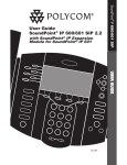
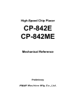
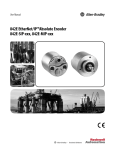
VECV Vehicle Sensor Demo Fixture (LED Based) User Manual Operating Instructions Start-up guide Brief theory of sensors Sensor mounting on fixture Resistance measurement test Understanding the working of Sensors Troubleshooting 1 VECV Table of Contents Start-up Guide ……………………………………………..……...….. 3 Checking the Contents Brief Theory of Sensors …………..……………………….……… 4 Cam (Phase) Sensor / Crankshaft Sensor Boost Pressure Sensor Sensor mounting on Fixture (Optional) ………..….……… 7 Cam (Phase) Sensor / Crankshaft Sensor Boost Pressure Sensor Resistance Measurement ……………..….………..….……… 8 Cam (Phase) Sensor / Crankshaft Sensor Boost Pressure Sensor Understanding the working of Sensors ….………..……. 9 Cam (Phase) Sensor / Crankshaft Sensor Boost Pressure Sensor Troubleshooting ……………………….……..…………………… 11 2 VECV Start-up Guide Checking the Contents Vehicle Sensors unit consists following – 1. Sensor Fixture - 1 (in PVC box) Cam (Phase) Sensor / Crankshaft Sensor Fixture – 1 unit 2. Sensor Fixture - 2 (in PVC box) Boost Pressure Sensor Fixture PVC pipe – 1 unit – 1 pc 3 VECV Brief Theory of Components 4 VECV 5 VECV 6 VECV Sensor mounting on fixture (Optional) If sensor is not mounted on Demo Fixture, then follow below steps to mount sensor on fixture. Tools required Screwdriver, suitable size – 1 no. Spanner, No.10 – 2 no. Cam / Crankshaft Sensor Fixture - Take Cam (Phase) sensor / Crankshaft sensor. - Perform Resistance measurement on sensor. - Remove Nut-Bolt which is attached to L clip. - Fix the sensor to L clip as shown below. - Maintain air gap between flywheel & sensor as 0.7 to 1.4mm. Accordingly add / remove the washers in between sensor & L clip. - Insert Wire-lug into sensor terminals. Interchange of these wires does not affect performance. - Now sensor fixture is ready for demo. Boost Pressure Sensor Fixture - Take Boost pressure sensor. - Perform Resistance measurement on sensor. - Remove top nut which is attached to vertical bolt. - Put the sensor in bolt & fix it with top nut, as shown below. - Keep the sensor horizontally with base plate. Accordingly adjust the height of nut. - Insert Wire-lug into sensor terminals as per tag attached. Interchange of these wires may damage the sensor / circuit. - Now sensor fixture is ready for demo. 7 VECV Resistance Measurement All checks described below are performed using Digital Multi meter (DMM). The actual values are measured between corresponding terminals and compared with the specified rated (Nominal) values. Resistance measurement of individual sensor – Sr. No. 1 Check Cam (Phase) sensor / Crankshaft sensor Boost Pressure sensor -a) Pressure sensor b) Air temperature sensor 2 8 Sensor End 1 and 2 (as shown in figure 5) Rated value 835Ω / 882Ω 4 and 1 (as shown in figure 4) 2 and 1 (as shown in figure 4) 60Ω at Open Air 1.6kΩ at Room Temp. VECV Understanding the working of Sensors Preparation Take a pair of wire (Red/Black 1, metre long), insert banana plugs to DC power supply unit at 12V socket. Insert other end Red plug to Demo bench’s Red socket and Black plug to Demo bench’s Black socket. Now 12V DC supply is available at Demo bench to use. You can also use 12V DC supply directly from DC power supply unit to sensor fixture. Note: Always use 12V DC supply unless otherwise specified. Cam (Phase) sensor / Crankshaft sensor: Red LED – indicates variation in magnetic field Green LED – indicates generation of output voltage - Connect 12V DC supply to +V & --V terminals of sensor fixture. - Connect multi-meter to signal o/p terminals of sensor fixture. - Being AC, multi-meter terminals can be connected in any polarity. - Select multi-meter range as 2000mV/2V AC. - In ideal state, multi-meter reads zero voltage and all LEDs are off. - Now rotate flywheel in either direction, multi-meter will display voltage. - Red LED blinks as flywheel rotates. Blinking speed is proportional to flywheel speed. - Green LED blinks when output signal is generated. Blinking speed is fixed / constant and is not proportional to signal output voltage. 9 VECV Boost Pressure sensor: Red LED – indicates flow of supply voltage / current Yellow LED – indicates Pressure signal output voltage & blinks if pressure varies Green LED – indicates Temperature signal output voltage & blinks if temperature varies - Connect 12V DC supply to +V & --V terminals of sensor fixture. - Red LED will start glowing one by one. - After this, Yellow & Green LED will start glowing one by one. a) To measure Pressure signal o/p - Connect multi-meter red probe to Pressure signal o/p terminal of sensor fixture. - Connect multi-meter common/-V/GND black probe to --V terminal of sensor fixture. - Select multi-meter range as 2000mV/2V DC. - In ideal state, multi-meter reads around 887mV/0.887V for room pressure. - Yellow LED glows constant as Pressure is constant. - To create more pressure, insert pipe in sensor & blow air at other end of pipe. - Now multi-meter reading increases, as pressure increases. - Yellow LED blinks as pressure increases. Blinking speed is fixed / constant and is not proportional to pressure. Note – Green LED may blink when pressure is applied as flow of air increases the sensor temperature. b) To measure Temperature signal o/p - Connect multi-meter red probe to Temperature signal o/p terminal of sensor fixture. - Connect multi-meter common/-V/GND black probe to --V terminal of sensor fixture. - Select multi-meter range as 20V DC. - In ideal state, multi-meter reads around 2.55V for room temperature. - Green LED glows constant as temperature is constant. - To increase temperature, switch ON heater. - Red LED will start glowing one by one and at end bulb will glow. - Now multi-meter reading decreases, as temperature increases. - Yellow LED blinks as temperature varies. Blinking speed is fixed / constant and is not proportional to temperature. Note – Green LED will blink even if Heater/Bulb is switched off, till sensor temperature reaches to room temperature. 10 VECV Troubleshooting If sensor does not work properly, then perform voltage measurement to locate the fault. All checks described below are performed using Digital Multi meter (DMM). The actual values are measured between corresponding terminals and accordingly fault is located. Voltage measurement of sensor on fixture – Sr. No. 1 2 Sensor Fixture Check Cam (Phase) sensor / Crankshaft sensor Signal o/p Boost Pressure sensor Pressure signal o/p and –V Temp. signal o/p and --V 11 Observed value zero voltage Sensor Fault -a) 11.2V b) 0V -a) 4.7V b) 0V Pressure terminal (4) is open Pressure terminal (4) is short to -V NTC terminal (2) is open NTC terminal (2) is short to -V Open / short