1
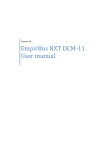
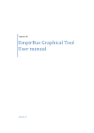
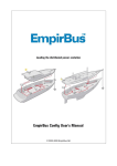
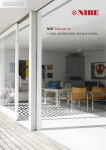
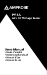
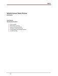
Trigentic AB
EmpirBus NXT SP-12
User manual
Covering models SP-12V-C, SP-12V-CL, SP-12V-CL-D, SP-12H-C, SP-12H-CL,
SP-12H-CL-D.
1.
Introduction ..................................................................................................................................... 2
2.
Scope of Delivery.............................................................................................................................. 2
3.
Model Range .................................................................................................................................... 2
4.
Installation........................................................................................................................................ 2
4.1 Mounting ........................................................................................................................................ 2
4.2 Connectors ..................................................................................................................................... 3
4.3 Terminal resistor switches ............................................................................................................. 4
5.
Buttons ............................................................................................................................................. 5
5.1 Button orientation ......................................................................................................................... 5
6.
Design ............................................................................................................................................... 6
6.1 Button design ................................................................................................................................. 6
6.2 Display layout design...................................................................................................................... 6
7.
Product specifications ...................................................................................................................... 7
Notes: ....................................................................................................................................................... 8
1/11
EmpirBus NXT SP-12 User manual Ver 1.0
1. Introduction
The SP-12 is a product from the EmpirBus NXT product family.
This document contains basic specifications and installation instructions. This and other documents
are available at www.empirbus.com.
2. Scope of Delivery
The SP-12 is delivered with 4 pc T6 mounting screws for thermo plastic mounting. Screws require
predrilled 1 mm holes.
3. Model Range
Both the unit and the box are marked with model number.
Vertical model
Horizontal model
Buttons (switches)
NMEA2000
LIN
Display
SP-12V-C
SP-12H-C
12 (24)
X
SP-12V-CL
SP-12H-CL
12 (24)
X
X
SP-12V-CL-D
SP-12H-CL-D
10 (20)
X
X
X
Table 3.1: Model range
4. Installation
4.1 Mounting
The SP-12 should be mounted on a flat vertical surface with four screws. This product is not
approved for engine room installation.
128
12
116
37
6
30
79
91
2
Ø2
89
9
[mm] (Drawing is not to scale.)
EmpirBus NXT SP-12 User manual Ver 1.0
2/11
4.2 Connectors
The connector marked CAN is for NMEA2000 and the connector marked AUX is for LIN. The panel
cable should be mounted with the text in the rubber mold facing upwards and on the 4 pin connector
the brown and white cable should be on top. See figure 4.1.
1 2 3.
COM.
UP.
Figure 4.1: SP-12V-CL-D and SP-12H-C
AUX.
Figure 4.1: SP-12 showing labels for the COM and AUX connectors, the rubber mold on
the panel cable marked UP and terminal resistor switches 1 through 3.
3/11
EmpirBus NXT SP-12 User manual Ver 1.0
4.3 Terminal resistor switches
The SP-12 has onboard terminal resistors that can be connected to the bus using switches located
beneath button 5 on a horizontal panel and under button 8 on a vertical panel. See figure 4.1, 5.1
and 5.2 for position of the switch.
ON .
1 2 3.
Figure 4.2: Internal terminal resistor switches
The switch is on as it is pushed towards on, and off as it is pushed towards the numbers. Switch 1 and
2 will individually add 120 Ω to the CAN bus Switch 3 will add 1 kΩ to the LIN bus.
The NMEA2000 requires a total resistance of the bus of 60Ω which is achieved by two parallel 120
resistors. If the SP-12 panel is placed within 6 meters from the end of the bus, an internal terminal
resistor in the SP-12 can be used to exclude one external terminal resistor.
If the total bus length is shorter than 6 meters, both external terminal resistors can be excluded by
using both of the internal terminal resistors in the SP-12.
MCU-11
Bus power feed
DCM-11
SP-12 with terminal
resistor switch 1
and 2 switched on
Figure 4.4: Bus example with total bus length less than 6 meter
EmpirBus NXT SP-12 User manual Ver 1.0
4/11
5. Buttons
For each button there are three indicator windows. The indicators can be programmed individually
and can indicate red or green. Each button has two switches – left side and right side – that can be
programmed individually. N.B.:The buttons are designed to snap firmly to the SP-12 switches and
are not designed to be detached once mounted on the panel.
5.1 Button orientation
1
2
2
3
4
4
5
6
5
6
7
8
7
8
9
10
9
10
11
12
11
12
Figure 5.1: Button orientation on vertical panels
1
2
3
2
3
4
5
6
5
6
7
8
9
7
8
9
10
11
12
10
11
12
Figure 5.2: Button orientation on horizontal panels
The frame of the SP-12 panel should be mounted so that the EmpirBus logo is placed next to button
12. Compare figure 5.1, 5.2 and 6.1 for frame and button orientation.
5/11
EmpirBus NXT SP-12 User manual Ver 1.0
6. Design
Figure 6.1: SP-12 panels with designed buttons and display
6.1 Button design
A list with the currently available predesigned buttons can be found in the SP-12 button legend on
www.empirbus.com. Navigate to “NXT PRODUCTS” and “Download files”, the link is called “SP-12
Button Legend [release date]”.
New buttons can also be designed per request for a fee.
6.2 Display layout design
The display of the SP-12V-CL-D and SP-12V-CL-D can be designed with custom images and logos in
24-bit color. The screen resolution is 160 x 128 and the display backlight can be programmed to fit
the light environment.
For questions regarding equipment and software for display layout design, contact the Trigentic
support.
EmpirBus NXT SP-12 User manual Ver 1.0
6/11
7. Product specifications
See table 3.1 for model specification and hardware support
Communication
CAN-bus
LIN
Power supply
Max/average
Supply voltage
Connectors
NMEA 2000
LIN
Environment
Ambient temperature
Enclosure
Physical data
Size
Weight
7/11
NMEA2000
Not yet supported
500mA/0,25mA
9-32VDC (Note: Power feed is through the NMEA 2000 bus)
SP-12 panel cable (art.no: 2036055, 2036056 or 2036057)
Not yet supported
-20 to +70 degrees Celsius
Ingress Protection IP20
128 x 91 x 12 mm
0,2 kg
EmpirBus NXT SP-12 User manual Ver 1.0
Notes:
EmpirBus NXT SP-12 User manual Ver 1.0
8/11
DECLARATION OF CONFIRMITY
We, manufacturer, Trigentic AB, Kasenabbevägen 65, S-45150 Uddevalla, Sweden, declare that the
articles:
2010101, 2010102, 2010103, 2010104, 2010105, 2010403, 2010505, 2020106, 2020107, 2020108,
2020109, 2020110, 2020408, 2020510, 2041311, 2041351, 2041314, 2041354, 2041313, 2041353
2061001, 2051001, 2051011 and 2051040,
are in conformity with the EMC Directive,
Low Voltage Directive 2006/95/EC, EN 60950
EMC Directive 2004/108/EC
CE MARK FIRST AFFIXED DATE
18th April 2013
We also declare that the articles:
2010101, 2010102, 2010103, 2010104, 2010105, 2010403, 2010505, 2020106, 2020107, 2020108,
2020109, 2020110, 2020408, 2020510, 2041311, 2041351, 2041314, 2041354, 2041313, 2041353
2061001, 2051001, 2051011 and 2051040,
comply with
FCC 47 CFR Part 15, Subpart B, Class A.
FCC MARK FIRST AFFIXED DATE
17th June 2013
SIGNS ON BEHALF OF
Trigentic AB
Name:
Henrik Niklasson
Position:
Managing Director
Location and date:
Uddevalla, Sweden, 10th of July 2013
Signature:
____________________________________
9/11
EmpirBus NXT SP-12 User manual Ver 1.0
RoHS CERTIFICATE OF CONFORMANCE
We, manufacturer, Trigentic AB, Kasenabbevägen 65, S-45150 Uddevalla, Sweden, declare that the
articles:
2010101, 2010102, 2010103, 2010104, 2010105, 2010403, 2010505, 2020106, 2020107, 2020108,
2020109, 2020110, 2020408, 2020510, 2041311, 2041351, 2041314, 2041354, 2041313, 2041353
2061001, 2051001, 2051011 and 2051040,
are in compliance with Directive 2002/95/EC on the restriction of the use of certain hazardous
substances in mechanics, electrical and electronic equipment (RoHS Directives).
SIGNS ON BEHALF OF
Trigentic AB
Name:
Henrik Niklasson
Position:
Managing Director
Location and date:
Uddevalla, Sweden, 10th of July 2013
Signature:
______________________________
EmpirBus NXT SP-12 User manual Ver 1.0
10/11
Trigentic AB
Kasenabbevägen 65
SE-451 50 Uddevalla
Sweden
11/11
Support
Phone: +46 522-44 22 22
E-mail: [email protected]
Web: www.empirbus.com
EmpirBus NXT SP-12 User manual Ver 1.0