1
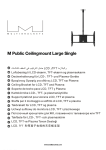
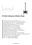
User manual
Elektronik und
Feinwerktechnik GmbH
Module und Geräte zum Eingeben,
Auswerten, Anzeigen und Ausdrucken
analoger und digitaler Daten.
GeBE IR-Protocol
Infrared-Protocol
for GeBE Thermal Printer
GeBE Document-No.
MAN-E-395-V2.0
Status: 25.07.2002
Printed: 03.09.2002
German: MAN-D-394
• Bi-directional Transfer
• Wireless Independence
• Handshake Mode
• Interference-Safe
Errors and changes reserved.
The technical data given are non-committal information and do not represent any assurance of certain features.
GeBE Elektronik und Feinwerktechnik GmbH
Beethovenstr. 15 • 82110 Germering • Germany • www.oem-printer.com
Phone:++49 (0) 89/894141-0 • Fax:++49 (0) 89/8402168 • email: [email protected]
GeBE E+F GmbH • www.oem-printer.com • User manual • GeBE IR-Protocol
Page 1 of 8
Content
0. Introduction
3
1. PC Test Program
3
2. Physical Characteristics
3
2.1. Transfer Mode
3
2.2. Settings
3
3. Data Structure
4
3.1. Packet I
4
3.2. Printer Status
Protocol Extension for GE-2998
4
3.2.1. Voltage Results of the Last Battery Test Command
5
3.2.2. Printer Status
5
3.3. Packet II
5
4.1. Transfer Protocol
6
4.2. Receive Protocol
7
5. Timing Diagram
8
GeBE E+F GmbH • www.oem-printer.com • User manual • GeBE IR-Protocol
Page 2 of 8
0. Introduction
For wireless transfer GeBE offers a convenient infrared interface for a number of GeBE printers.
The transfer is based on the SHARP IR protocol. Unlike the IrDA protocol, the Sharp IR protocol
does not have any software layers that are used for communication in networks or for controlling
the hardware. The Sharp IR is similar to the software layer IrCOMM of the IrDA standard. The
Sharp IR provides for a simple and cost-effective optional master-slave connection to integrate the
IR protocol itself into existing systems. For operation with a printer, the protocol has been extended to monitor the printer functions.
1. PC Test Program
For the first developmental phase GeBE offers a test program.
The program allows the transfer of any files through a COM interface to an infrared interface.
The system requirements for the program "GeBE-IR-Transmit.exe" are an IBM compatible PC,
operating system Win 95 or 98, and a GeBE IR adapter GSW-IR or similar interface that connects
to a COM interface.
2. Physical Characteristics
2.1. Transfer Mode
The physical transfer is compatible to the IrDA SIR hardware layer.
This procedure is used for transfer rates from 2,400 bps to 115 kbps. These speeds correspond
with a standard serial interface. The hardware layers IrDA FIR and 4 ppm are not supported.
This puts the bit intervals between 417 ±s and 8.7 ±s ( ~ 20±s at 9,600bps).
An impulse of 3/16 of the impulse width represents logic 1. The light levels are in a range between
40 mW/sr (milliwatt/steradian) and 500 mW/sr. The distance between host and receiver is specified
as 1cm to 1 m.
start
stop
0
1
0
0
1 1
0
1
0
NRZ DATA
1
IrDA-SIR HIGH =
LIGHT TRANSMITTED
2.2. Settings
9,600 baud (2,400 - 115,200 bps possible on request)
no parity
1 stop bit
infrared impulse length 3/16 bit time ( ~ 20 ±s at 9600bps).
( fixed impulse length of 1.63 ±s is not possible )
After the switch from receive to transmit mode, the IR hardware needs a short time period of about
2ms. We therefore recommend to wait for 3 ms after receiving the last block before sending again.
GeBE E+F GmbH • www.oem-printer.com • User manual • GeBE IR-Protocol
Page 3 of 8
3. Data Structure
There are two types of transmit packets.
Packet I is used for the transfer of control commands and messages, see table 1.
Packet II is used for transmitting data to the printer.
Since the IR units are not defined from the beginning, the transfer of either packet type is initiated
with 5 dummy characters (00 Hex) and a START ID (96 Hex). The printer has to process at least
two dummy charaters correctly, before the start ID is considered.
Afterwards, the packet ID is transferred: 82 Hex for packet I , 81 Hex for packet II.
3.1. Packet I
Data Format Packet I:
DUMMY
START ID
PACKET ID
DATA
Number of Bytes
Value
5
1
1
1
00h
96h
82h
value see table 1
Example for a transfer request: ENQ
DUMMY
00h, 00h, 00h, 00h,00h
3.2. Printer Status
START ID
96h,
PACKET ID
82h,
DATA
05h
Protocol Extension for GE-2998
Four additional bytes that indicate the exact printer status are attached to both the SYN and the
CAN packet. All four parameters are coded binarily.
In old software versions, these bytes should be rejected.
SYN Packet:
---------< 5 * NULL > < START-ID > < PACKET1 > < SYN >
< Vp-noload > < Vp-load > < Errorflags1 > < Errorflags2 >
CAN-Packet:
---------< 5 * NULL> < START-ID > < PACKET1 > < CAN >
< Vp-noload > < Vp-load > < Errorflags1 > < Errorflags2 >
GeBE E+F GmbH • www.oem-printer.com • User manual • GeBE IR-Protocol
Page 4 of 8
3.2.1. Voltage Results of the Last Battery Test Command
In printers that have a battery test command, the last measured values are transmitted. Otherwise,
these bytes are "0".
In order to perform a battery test, the battery test command has to be given in the last packet II.
With the next SYN or CAN packet from the printer, the measured values are sent as < Vp-noload >
< Vp-load >.
You can find the description of the test command in the corresponding printer manual.
< Vp-noload > :
Gives the no-load battery idle voltage immediately before the last battery test command in binary
code.
< Vp-load >
Gives the load battery voltage after the last battery test command in binary code.
3.2.2. Printer Status
The following two bytes < Errorflags1 > < Errorflags2 > report the printer status.
Attention:
Some printer models do not have all error reports or messages available. In this case, all bits are
always set to "0".
3.3. Packet II
The maximum data block size is 128 bytes, not including the header.
If more than 128 bytes have to be transmitted, they have to be split into several sequential blocks.
For every 2-byte value, the low byte will be transferred first (BLOCK No, DLENGTH, CHKSUM).
The last block contains the block number FFFF Hex. It does not need to be completely filled to128
bytes.
Checksum
CHKSUM is the sum (2 bytes ) of all data (DATA 1-128).
Example:
Content of data block: 15h 24h 01h 55h 63h 77h 43h 77h 8Fh 9Ch
sum = 034Eh --> low byte = 4Eh
high byte = 03h
Data Format Packet II:
DUMMY
START ID
PACKET ID
VERSION
BLOCK No
CTRL CODE
DEV CODE
ID CODE
DLENGTH
DATA
CHKSUM
Number of Bytes
Value
5
1
1
1
2 (L/H)
1
1
1
2 (L/H)
1 - 128
2 (L/H)
00h
96h
81h
10h
0001h - FFFFh
01h
fixed
40h
fixed
FEh
fixed
0001h - 0200h
GeBE E+F GmbH • www.oem-printer.com • User manual • GeBE IR-Protocol
Page 5 of 8
Example for a Data Transfer:
DUMMY
START ID
00h, 00h, 00h, 00h,00h 96h,
PACKET ID VERSION
81h,
10h
DEV CODE
ID CODE
DLENGTH
DATA
40h
FEh,
LOW
????h
HIGH
BLOCK NO
LOW HIGH
CTRL CODE
01h
CHEKSUM
LOW
HIGH
4. Software Protocol
4.1. Transfer Protocol
4.1.1
The host starts a "session" by transmitting a request ENQ (packet I). The printer
confirms the ENQ by transmitting a SYN message.
4.1.2
If the host receives a SYN packet, continue with 4.1.4.
4.1.3
If the host receives a CAN packet, or if the selected power-down time has passed and no SYN packet has been received, the host will end the session. If the
host receives any other packet, no packet, or an incomplete packet, it will
start transmitting ENQ packets every 0.5 seconds (according to Sharp-IR for 6
minutes).
4.1.4
If the host receives a SYN packet, it will transmit a single packet II and wait for
an AKN packet from the printer.
4.1.5
When the host receives an ACK packet, the transmission is regarded as a suc
cess.
4.1.6
If the host does not receive an ACK packet or another packet I within 1 second
after the transmission of packet II, it will go back to step 4.1.1 and transmit the
data again. The repeated data transfer after AKN will only be performed once. If
this transmission also goes wrong, the session will be canceled.
A BUF packet should initiate several repeats. The number of possible repeated
block transfers should not be set too low. We recommend 20 repeats.
Since the print speed greatly depends on the operating voltage, the number of re
peats should be determined by the lowest occuring voltage.
GeBE E+F GmbH • www.oem-printer.com • User manual • GeBE IR-Protocol
Page 6 of 8
4.2. Receive Protocol
4.2.1
The receiver is activated by a DUMMY character. After the first recognized
DUMMY, it will wait for a packet I with ENQ. If no ENQ is received before the set
power-down time has passed, the printer will cancel the session and switch to
sleep mode.
4.2.2
If the printer receives an ENQ packet, it will either transmit a SYN packet to
continue the session, or a CAN packet to finish the session.
4.2.3
When the printer receives a valid packet II, it will transmit a packet I with ACK.
4.2.4
If an error occurs in packet II, or the time between two bytes is more than one
second, the printer will go back to step 4.2.1. without sending an ACK. This will
cause the host to transmit packet II again after 1 second.
4.2.5
If the checksum is faulty, the printer will send a packet I with NAK. This will initia
te an immediate repeat of packet II by the host.
Attention:
The data transfer in both directions is only possible "half duplex", because transmitter and receiver
both receive the signals sent by the other side plus their own transmit signals. For this reason, the
transmitting party has to turn off or filter out the receive signals during transfer.
GeBE E+F GmbH • www.oem-printer.com • User manual • GeBE IR-Protocol
Page 7 of 8
5. Timing Diagram
SEND
RECEIVE
ENQ( P acket I )
Typ. 0.5 sec.
ENQ( P acket I )
ENQ( P acket I )
SYN( P acket I )
( P acket I I )
M ax. 1 sec.
M i n. 3 msec.
M ax. 1 sec.
1 st
DATA Bl ock
ACK( P acket I )
( P acket I I )
M ax. 1 sec.
BUF( P acket I )
2 nd
DATA Bl ock
Buffer
full !!
( P acket I I )
M ax. 1 sec.
ACK( P acket I )
2 nd
DATA Bl ock
( P acket I I )
M ax. 1 sec.
ACK( P acket I )
3 rd
DATA Bl ock
GeBE E+F GmbH • www.oem-printer.com • User manual • GeBE IR-Protocol
Page 8 of 8