1
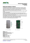
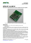
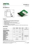
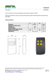
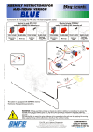
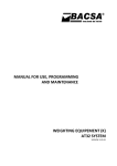
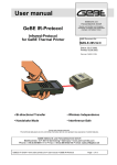
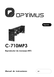
WIZ1-434-RS / WIZ1-434-D User Manual
WIZ1-434-RS WIZ1-434-D
Single channel, 9600 b/s, half-duplex data transceiver
module
Available models:
• WIZ1-434-RS: Data input by RS232 (±12V) logic, 9-15V supply (positive to central pin)
• WIZ1-434-D: Data input by TTL (0-5V) logic and RS232 timing system, 5V supply
Box and holder are optional (WIZ1-434-RSB, WIZ1-434-DB). The power supply is not shipped with the unit. It is
customer responsibility to supply voltage to the WIZ1 unit according to pertinent safety normatives.
WIZ1-434-RSB
Antenna
CE Mark is on the back side
of the plastic container (RSB
and DB mod.s) or on the
PCB (RS and D mod.s)
POWER, TX and RX
LEDS
RS232 connector
Power supply connector
The WIZ1-434-x modules are half-duplex, smart transceivers that support a digital data packet transfer of 1120 bytes length at 9600 b/s speed. The data transferred to the remote unit are error-free since at the arrival
are verified and confirmed.
Technical features
Operating frequency
Voltage supply
Power consumption TX – RX
RF output power
Data transmission speed
Operating temperature
Operating range
Data packet length
433.92 MHz
9-18 V
20-30 mA
10 mW
9600 bit/sec.
-20/+80 °C
40 m indoor – 150 m outdoor
1 – 120 Byte
i
AUR°EL S.p.A. Via Foro dei Tigli, 4 - 47015 Modigliana (FC) - ITALY
Tel.: +390546941124 – Fax: +390546941660
http://www.aurel.it - email: [email protected]
WIZ1-434-RS / WIZ1-434-D User Manual
Layout
The WIZ1-434-RS model are powered by a voltage supply range from 9 to
15V provided at the DC connector (1) and RS232 logic signals, on the female
9 pins connector D (2). The WIZ1-434-D model are powered by a 5V power
supply directly on the RS232 connector’s pin9 (originally RI signal, Ring
Indicator), and the signals, at the input, with 0-5V logic; they fully maintain
the characteristics of an RS232 signal (Start bit, data, parity, 1 Stop bit) and
differentiate from them exclusively for the electrical levels.
The serial port receives data on pin3, transmits data on pin2 and has on
pin7 (RTS) and pin8 (CTS) the programming signals.
1 9-15V DC supply connector
(*)
2 RS232, D type, female, 9 pins
connector
3 Programming jumper. From
connector RS232 toward the
antenna there are JP1, JP2,
JP3
4 Jumper ICP (In Circuit
Programming)
5 Voltage stabilizer 5V (*)
4
6
6 Microcontroller
5
7 8 9
7 POWER supply indication LED
3
8 TX/TESTING indication LED
9 RX indication LED
2
1
(*) for WIZ1-434-RS model only
To reach the 3 programming jumpers, remove, with care, the box front cover using a flat tip screwdriver
inserted in the slots provided at the 4 corners. The default jumpers are supplied opened.
Programming Jumpers
JP1
JP2
JP3
TX TEST
X
O
O
RX TEST
O
X
O
REMOTE PROGRAMMING
O
O
X
X= close jumper
O= open jumper
Module operation test
The WIZ1 modules are equipped with a radio connection test procedure that does not need their connections to
a personal computer or to a remote unit. It can be implemented by using two WIZ1 modules and by closing JP1
in the first module and JP2 in the second, before supplying power. According to the data transfer that took
place between the two modules, the TX LED shall remain on, while the RX LED shall blink. A further test can be
carried out by connecting a module to a PC and by setting a second module in REMOTE PROGRAMMING (JP3
closed): by interrogating the remote module and by verifying the answer it can be seen whether the radio link
is operating or not.
ii
AUR°EL S.p.A. Via Foro dei Tigli, 4 - 47015 Modigliana (FC) - ITALY
Tel.: +390546941124 – Fax: +390546941660
http://www.aurel.it - email: [email protected]
WIZ1-434-RS / WIZ1-434-D User Manual
WIZ1 modules addresses
WIZ1 modules are designed to be used in a master–slave system (max number of slaves 255). The distinction
between master unit and slave is related to the software type, according to the address introduced in the
ADDRESS register:
•
•
ADDRESS = 0: system MASTER module;
ADDRESS = 1 – 255: SLAVE module.
The system must always have a master module programmed with the address ‘0’.
The microcontroller embedded inside the WIZ1 modules administrates the data packet coming through the
RS232 gate; the addressing of the data packet to be transmitted, is carried out by the external system that
requires the connection with a remote unit. The address byte must be placed before the data bytes.
In case of a data packet addressed to another module, or in case of a cheksum test failure, the packet shall be
considered void and, therefore, not forwarded to the remote unit.
Data interchange between units
Data interchange between WIZ1 units follows the procedure illustrated here below:
1
SLAVE
MASTER
8,<H→
→R Data>
8,<H→
→R Data>
8,<H←
←R Data>
3
2
<H→
→R Data>
MASTER
ADDRESS=0
SLAVE
ADDRESS=8
8,<H←
←R Data>
6
5
<H←
←R Data>
H→
→R means Host to Remote communication
H←
←R means : Remote to Host communication
4
1. Data addressing is managed by the system placed upstream of the WIZ1 master module: the address byte of
the remote WIZ1 module, is placed before the data packet byte.
2. The packet is transmitted via radio channel by the WIZ1 master module.
iii
AUR°EL S.p.A. Via Foro dei Tigli, 4 - 47015 Modigliana (FC) - ITALY
Tel.: +390546941124 – Fax: +390546941660
http://www.aurel.it - email: [email protected]
WIZ1-434-RS / WIZ1-434-D User Manual
3. The packet is received by the WIZ1 remote module: if it is accepted, the useful data are forwarded to the
connected unit.
4. In case the packet is a command that foresees a reply from the remote unit, then the return data packet
shall be forwarded to the WIZ1 master module.
5. This unit (for example an industrial PLC or a sensor) IS NOT REQUIRED to put first in the data packet’s head,
the address of the unit from which the interrogation came (i.e.: the master): the slave module shall care to
place its own address before the data packet’s head (*).
6. The master module, at the reception via radio, of the data packets, DOES NOT CANCEL the byte of the
remote module address, by sending downstream all the data bytes received: this function appears to be
particularly useful in polling systems, where an answer data packet can reach the questioning unit with not well
defined delays.
This procedure is good for WIZ1 modules use in the industry, where PLCs can be directed to operate on
machines or questioned to monitor telemetry data. Being not equipped with the adequate logic, in order to
handle the data string that composes the answer to a possible interrogation, the WIZ1 remote module places,
therefore, in front of the data from the PLC its own address in order to avoid that the originated packet is
understood, from the other slave modules present in the system, as a command coming from the master
module (to all other users of the system the head address shall cause the rejection of the answer, taking into
consideration the unique of the addressing).
The minimum time between two consecutive packet transmissions should be 300ms.
(*) this device will avoid that an answer packet, coming from a slave module, is understood, as its own, by an
other slave module that has the address equal to the 1st byte of the data packet.
Programming of the internal registers
•
Programming via cable: The WIZ1 module takes up a data interchanging protocol RS232, without the
•
Programming via radio: the WIZ1 modules, specially the WIZ1-434-D model, can be programmed
use of the handshaking controls. The signals, employed to exchange the data, in regard of the 9 pins
connector D, present on the board, are TX (pin3), RX (pin2) and GND (pin5). The module programming via
cable, takes place by switching the lines RTS (pin 7) and CTS (pin 8). The RTS line shall be taken to a low
logic level
by the personal computer that has to programme the module before sending the selected
command. The microcontroller shall switch the CTS line, by lowering it within the end of the packet
reception, and raising it up again once the programming operation is over. In both cases the programming
operation of the microcontroller internal parameters can take place or can be read from the EEPROM on
which they are recorded. The programming procedure foresees the sending of a command of the type
WRITE or READ (WRITE: #,<address byte>,<value byte>; READ: $,<address>).
without the physical connection to a personal computer, by sending the registers writing commands via
radio, to the remote module, with JP3 closed. The programming procedure via radio must involve one WIZ1
module only at a time. In case there is a need to programme more modules, repeat the above mentioned
sequence for each of them.
The programming via radio differs from the one via cable for the jp3 jumper closing in the remote module and
for the non administration of the RTS and CTS lines from the personal computer that has to conduct the
operation.
iv
AUR°EL S.p.A. Via Foro dei Tigli, 4 - 47015 Modigliana (FC) - ITALY
Tel.: +390546941124 – Fax: +390546941660
http://www.aurel.it - email: [email protected]
WIZ1-434-RS / WIZ1-434-D User Manual
Here below the registers list, their address and their functions.
REGISTER NAME ADDRESS FUNCTION
ADDRESS
DELAY
$00
$01
SYNCHAR
$02
RS232
$03
RELEASE
$1f
DEFAULT
WRITE /
READ
WIZ1 module address
$00
Carrier turn on delay (number of bytes to be $03
transmitted as a synchronism’s preamble)
(=3 Tbyte)
Character transmitted as synchronism preamble
$FF
W/R
W/R
RS232 protocol options:
00: no parity
01: odd parity
02: not in use
03: even parity
Microcontroller firmware version
R/W
$01
(odd
parity)
$01
W/R
R
Registers $04→$1d content is not applied for WIZ1-434-x modules.
Please pay attention to RS232 register programming because change of its value could prevent execution of
software applications where parity cannot be changed.
Reference to CE Approvals
To meet CEPT Recommendation 70-03, device must be used in transmission mode for a maximum timing duty
cycle less than 10% (max 6 minutes in transmission in an hour). Device usage is subject to laws and rules of
the Country (e.g.: in Italy – Codice Postale e delle Telecomunicazioni – art. 334 – and subsequent laws).
Test and technical reports performed at testing lab: PRIMA RICERCA & SVILUPPO – via Campagna, 58 –
22020 Gaggino Faloppio (CO) - Italy
v
AUR°EL S.p.A. Via Foro dei Tigli, 4 - 47015 Modigliana (FC) - ITALY
Tel.: +390546941124 – Fax: +390546941660
http://www.aurel.it - email: [email protected]