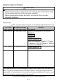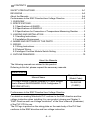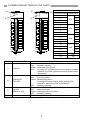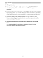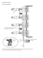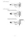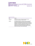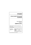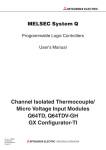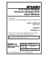
1
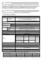
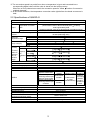
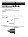
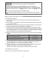
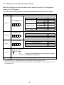
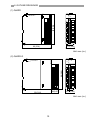
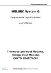
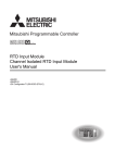
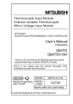
RTD Input Module
Channel Isolated RTD
Input Module
MITSUBISHI
General-Purpose PROGRAMMABLE LOGIC CONTROLLER
User’s Manual
(Hardware)
Q64RD
Q64RD-G
Thank you for purchasing the Mitsubishi general-purpose
programmable logic controller MELSEC-Q series.
Prior to use, please read this manual thoroughly and
familiarize yourself with the product
MODEL
Q64RD-U-H-JE
MODEL
CODE
13JT31
IB(NA)-0800156-C(0610)MEE
© 2000 MITSUBISHI ELECTRIC CORPORATION
SAFETY PRECAUTIONS
(Read these precautions before using.)
When using Mitsubishi equipment, thoroughly read this manual and the
associated manuals introduced in this manual. Also pay careful attention to
safety and handle the module properly.
These SAFETY PRECAUTIONS classify the safety precautions into two
categories: "DANGER" and "CAUTION".
DANGER
Procedures which may lead to a dangerous condition and
cause death or serious injury, if not carried out properly.
CAUTION
Procedures which may lead to a dangerous condition and
cause superficial to medium injury, or physical damage
only, if not carried out properly.
Depending on circumstances, procedures indicated by
CAUTION may also
be linked to serious results.
In any case, it is important to follow the directions for usage.
Store this manual in a safe place so that you can take it out and read it
whenever necessary. Always forward it to the end user.
[DESIGN PRECAUTIONS]
DANGER
Do not write data into the "system area" of the buffer memory of intelligent
function modules. Also, do not use any "prohibited to use" signals as an
output signal to an intelligent function module from the PLC CPU.
Writing data into the "system area" or outputting a signal for "prohibited to
use" may cause a PLC system malfunction.
CAUTION
Do not bunch the control wires or communication cables with the main
circuit or power wires, or install them close to each other.
They should be installed 100 mm(3.94 inch) or more from each other.
Not doing so could result in noise that may cause malfunction.
A-1
[INSTALLATION PRECAUTIONS]
CAUTION
Use the PLC in an environment that meets the general specifications
contained in the CPU user's manual.
Using this PLC in an environment outside the range of the general
specifications may cause electric shock, fire, malfunction, and damage to
or deterioration of the product.
When installing the module, securely insert the module fixing tabs into the
mounting holes of the base module while pressing the installation lever
located at the bottom of the module downward.
Improper installation may result in malfunction, breakdown or the module
coming loose and dropping. Securely fix the module with screws if it is
subject to vibration during use.
Tighten the screws within the range of specified torque.
If the screws are loose, it may cause the module to fallout, short circuits, or
malfunction.
If the screws are tightened too much, it may cause damage to the screw
and/or the module, resulting in fallout, short circuits or malfunction.
Switch all phases of the external power supply off when mounting or
removing the module.
Not ding so may cause electric shock or damage to the module.
Do not directly touch the conductive area or electronic components of the
module. Doing so may cause malfunction or failure in the module.
[WIRING PRECAUTIONS]
CAUTION
Always ground the FG terminal for the PLC.
There is a risk of electric shock or malfunction.
When turning on the power and operating the module after wiring is
completed, always attach the terminal cover that comes with the product.
There is a risk of electric shock if the terminal cover is not attached.
Tighten the terminal screws within the range of specified torque.
If the terminal screws are loose, it may result in short circuits or malfunction.If
the terminal screws are tightened too much, it may cause damage to the screw
and/or the module, resulting in short circuits or malfunction.
Be careful not to let foreign matter such as sawdust or wire chips get inside
the module.They may cause fires, failure or malfunction.
A-2
[WIRING PRECAUTIONS]
CAUTION
The top surface of the module is covered with protective film to prevent
foreign objects such as cable offcuts from entering the module when wiring.
Do not remove this film until the wiring is complete.
Before operating the system, be sure to remove the film to provide
adequate ventilation.
REVISIONS
The manual number is given on the bottom right of the top cover.
Print Date
Nov., 2000
Jun., 2003
Manual Number
Revision
IB (NA)-0800156-A First edition
IB (NA)-0800156-B Added the description of the model,
Q64RD-G.
Addition
Section 2.2
Partial correction
About the Manuals, Chapter 1, Chapter
2, Section 2.1 to 2.3, Chapter 4, Section
5.1, 5.2, 5.3, Chapter 6
Oct., 2006
IB (NA)-0800156-C
Partial correction
Section 5.3
This manual confers no industrial property rights or any rights of any other kind, nor
dose it confer any patent licenses. Mitsubishi Electric Corporation cannot be held
responsible for any problems involving industrial property rights which may occur as
a result of using the contents noted in this manual.
© 2000 MITSUBISHI ELECTRIC CORPORATION
A-3
CONTENTS
SAFETY PRECAUTIONS ............................................................................. A-1
REVISIONS .................................................................................................. A-3
About the Manuals ........................................................................................ A-4
Conformance to the EMC Directive/Low Voltage Directive............................ A-4
1. OVERVIEW................................................................................................... 1
2. SPECIFICATIONS ........................................................................................ 1
2.1 Specifications of Q64RD ......................................................................... 1
2.2 Specifications of Q64RD-G ..................................................................... 2
2.3 Specifications for Connection of Temperature-Measuring Resistor ......... 3
3. LOADING AND INSTALLATION ................................................................... 4
3.1 Handling Instructions............................................................................... 4
3.2 Installation Environment .......................................................................... 4
4. NAMES AND SETTINGS OF THE PARTS ................................................... 5
5. WIRING......................................................................................................... 6
5.1 Wiring Instructions................................................................................... 6
5.2 External Wiring........................................................................................ 7
5.3 Intelligent Function Module Switch Setting .............................................. 9
6. OUTLINE DRAWINGS ................................................................................ 10
About the Manuals
The following manuals are related to this product.
Referring to this list, please request the necessary manuals.
Detailed manual
Manual Number
(Model Code)
Manual Name
RTD Input Module Channel Isolated RTD Input Module
User's Manual Q64RD/Q64RD-G/GX Configurator-TI
(SW1D5C-QTIU-E)
SH-080142
(13JR31)
Conformance to the EMC Directive/Low Voltage Directive
For details on making Mitsubishi PLC conform to the EMC directive and low
voltage instruction when installing it in your product, please see Chapter 3,
"EMC Directive and Low Voltage Instruction" of the User's Manual (Hardware)
of the PLC CPU to use.
The CE logo is printed on the rating plate on the main body of the PLC that
conforms to the EMC directive and low voltage instruction.
A-4
1. OVERVIEW
This user's manual provides the specifications, handling instructions, part names
and others of the Q64RD platinum RTD temperature input module (referred to as
Q64RD) and the Q64RD-G channel isolated RTD temperature input module
(referred to as Q64RD-G) used with the MELSEC-Q series CPU module.
2. SPECIFICATIONS
The following are the specifications of the Q64RD/Q64RD-G.
2.1 Specifications of Q64RD
Item
Number of channels
Output
Specifications
4 channels
16-bit, signed binary data
(-2000 to 8500: Value to the first decimal place 10)
32-bit, signed binary data
(-200000 to 850000: Value to the third decimal place 1000)
16-bit, signed binary data
Temperature
conversion value
Scaling value
Usable platinum temperaturemeasuring resistors
Measured temperature Pt100
range
JPt100
Pt100
Range changing
JPt100
Ambient temperature
0 to 55
Accuracy *1
Ambient temperature
25 5
Resolution
Conversion speed
Number of analog input points
Temperature detecting output current
2
E PROM write count
Pt100 (JIS C1604-1997, IEC 751 1983), JPt100 (JIS C1604-1981)
-200 to 850
-180 to 600
-20 to 120 / -200 to 850
-20 to 120 / -180 to 600
0.25% (accuracy relative to maximum value)
0.08% (accuracy relative to maximum value)
0.025
40ms/channel *2
4 channels/module
1mA
Max. 100,000 times
Isolation
method
Specific isolated area
Isolation
Between platinum
temperature-measuring Photocoupler
isolation
resistor input and PLC
power supply
Between platinum
temperature-measuring No isolation
resistor input channels
Wire break detection
Number of occupied points
Connection terminals
Applicable wire size
Applicable crimping terminals
Cables between Q64RD and platinum
temperature-measuring resistor
Internal current consumption (5VDC)
Weight
Outline dimensions
Dielectric
withstand voltage
Isolation
resistance
1780VrmsAC/
3 cycles
(Altitude 2000m)
10MΩ or
more using
500VDC
isolation
resistance
tester
-
Yes (Each channel independent) *3
16 points
18-point terminal block
2
0.3 to 0.75mm
1.25-3 R1.25-3 (Sleeved crimping terminals are unusable)
Refer to Section 2.3.
98(H)
0.60A
0.17kg
27.4(W) 90(D) mm
*1 The selection ranges and accuracies have the following relationships.
Selection Range
Ambient Temperature
0 to 55
25 5
Pt100 and JPt100:
-20 to 120
0.3
0.096
1
Pt100:
-200 to 850
2.125
0.68
JPt100:
-180 to 600
1.5
0.48
*2 The conversion speed is a period from when a temperature is input and converted into a
corresponding digital value until the value is stored into the buffer memory.
When two or more channels are used, the conversion speed is "40ms number of conversion
enabled channels".
*3 At wire break detection, the temperature conversion value right before wire break occurrence is
held.
2.2 Specifications of Q64RD-G
Item
Number of channels
Output
Temperature conversion
value
Scaling value
Usable temperature-measuring
resistors
Pt100
Measured
JPt100
temperature range
Ni100Ω
Pt100
JPt100
Range changing
Ni100Ω
Reference accuracy *2
Accuracy
Pt100/JPt100
*1
(-20 to 120 )
(Accuracy
Tempera- Pt100/JPt100
relative to
ture
(0 to 200 )
maximum
coefficient Pt100/JPt100
value of
*3
(-200 to 850 )
selection
Pt100/JPt100
range)
(-60 to 180 )
Resolution
Conversion speed
Number of analog input points
Temperature detecting output current
2
E PROM write count
Specifications
4 channels
16-bit, signed binary data
(-2000 to 8500: Value to the first decimal place 10 times)
32-bit, signed binary data
(-200000 to 850000: Value to the third decimal place 1000 times)
16-bit, signed binary data
Pt100 (JIS C1604-1997, IEC 751 1983), JPt100 (JIS C1604-1981),
Ni100Ω (DIN43760 1987)
-200 to 850
-180 to 600
-60 to 180
-20 to 120 /0 to -200 / -200 to 850
-20 to 120 /0 to -200 / -180 to 600
Within 0.04%
70ppm/
( 0.0070%/ )
65ppm/
( 0.0065%/ )
50ppm/
( 0.0050%/ )
70ppm/
( 0.0070%/ )
0.025
40ms/channel *4
4 channels/module
1mA
Max. 100000 times
Isolation
method
Dielectric
Isolation
withstand voltage resistance
Between temperature10MΩ or
Photocoupler
measuring resistor input
more
using
1780VrmsAC/
isolation
and PLC power supply
500VDC
3 cycles
Between temperatureisolation
Transformer (Altitude 2000m)
measuring resistor input
resistance
isolation
channels
tester
Specific isolated area
Isolation
Wire break detection
Number of occupied points
Connection terminals
Applicable wire size
Applicable crimping terminals
Cables between Q64RD-G and
temperature-measuring resistor
Internal current consumption (5VDC)
Weight
Outline dimensions
Yes (Each channel independent) *5
16 points
18-point terminal block
2
0.3 to 0.75mm
1.25-3 R1.25-3 (Sleeved crimping terminals are not usable.)
Refer to Section 2.3.
98(H)
2
0.62A
0.20kg
27.4(W) 112(D) mm
*1 The selection ranges and accuracies have the following relationships.
Selection Range
Ambient Temperature
0 to 55
25 5
Pt100 and JPt100:
-20 to 120
0.300
0.090
Pt100:
-200 to 850
1.615
0.553
Selection Range
Ambient Temperature
0 to 55
25 5
Pt100 and JPt100:
0 to 200
0.470
0.145
Pt100:
-60 to 180
0.450
0.135
JPt100:
-180 to 600
1.140
0.390
*2 Accuracy in ambient temperature and wire resistance when the offset/gain setting is set.
*3 Accuracy per 1-degree temperature change
Example) Accuracy for the case of changing from 25 to 30
0.04% (Reference accuracy) + 0.0070%/ (Temperature coefficient) 5
(Temperature difference) = 0.075%
*4 The conversion speed is a period from when a temperature is input and converted into a
corresponding digital value until the value is stored into the buffer memory.
When two or more channels are used, the conversion speed is "40ms number of conversion
enabled channels".
*5 At wire break detection, the temperature conversion value right before wire break occurrence is
held.
2.3 Specifications for Connection of Temperature-Measuring Resistor
(1) For 3-wire type
The wire resistance value should satisfy the condition of 1) + 2) 2 max.
In addition, the difference of the wire resistance value between 1) and 2)
should be 10 max.
Q64RD/Q64RD-G
Wire
2)
a1
A1
Pt100
B1
b1
1)
SLD
(2) For 4-wire type
The wire resistance value should satisfy the condition of 1) + 2)
Q64RD/Q64RD-G
Wire
a1
2)
A1
Pt100
B1
b1
1)
SLD
3
2
max.
POINT
Wire resistance values may be an error factor in the temperature
measurement.
The error arisen between the Q64RD/Q64RD-G and the temperaturemeasuring resistor (between the wire resistance value 1) + 2) and measured
temperature value) is Max. 0.007 /2 (Q64RD) or Max. 0.003 /2 (Q64RDG).
This error can be corrected by the offset/gain setting.
When making offset/gain adjustment, set the wire resistance value actually
used.
3. LOADING AND INSTALLATION
3.1 Handling Instructions
(1) Do not drop the case and connectors of the module and subject them to
hard impact.
(2) Do not remove the printed circuit boards of the module from the case. Doing
so can cause a failure.
(3) Be careful to prevent wire-offcuts and other foreign matter from entering the
module. They can cause a fire, failure or malfunction.
(4) To prevent wire-offcuts and other foreign matter from entering the module
during wiring, the module carries a foreign matter ingress prevention label at
its top. During wiring, do not remove this label. For system operation, always
remove this label to ensure adequate heat dissipation.
(5) Tighten the mounting and terminal screws of the module within the following
ranges.
Screw Location
Tightening Torque Range
Module mounting screw (M3 screw)
0.36 to 0.48N y m
Terminal block terminal screw (M3 screw)
0.42 to 0.58N y m
Terminal block mounting screw (M3.5 screw)
0.66 to 0.89N y m
(6) To mount the module on the base, securely insert the module fastening latch
into the fastening hole on the base. Improper installation may result in a
module malfunction, or may cause the module to fall off.
(7) Always make sure to touch the grounded metal to discharge the electricity
charged in the body, etc., before touching the module.
Failure to do so may cause a failure or malfunctions of the module.
3.2 Installation Environment
Refer to the user's manual of the CPU module used.
4
4. NAMES AND SETTINGS OF THE PARTS
1)
1)
Q64RD
RUN
RUN
ERROR
ERR.
2)
Terminal Block Layout
Q64RD-G
ALM
CH2
a1
1
A1
2
B1
3
b1
4
CH4
3
2
3
4
b1
B1
5
a2
B2
4
5
6
7
b2
8
a3
9
8
b2
a3
B2
b2
8
a3
9
A3
10
A3
10
9
B3
11
B3
11
b3
12
b3
12
13
10
a2
a4
13
A4
14
A4
14
B4
15
B4
15
b4
16
b4
SLD
17
SLD
18
(FG)
CH4
a4
(FG)
6
7
11
CH2
CH3
Number Name and Appearance
1)
RUN LED
2)
ERROR LED
ERR. LED
3)
ALM LED
(Q64RD-G only)
4)
Terminal block
A2
B2
A3
B3
b3
16
13
a4
17
18
14
15
CH4
16
4)
B1
12
Q64RD
-G
Q64RD
A1
1
A2
CH3
CH1
a1
b1
CH2
a1
A1
5
6
7
a2
A2
CH3
2
CH1
Signal name
1
2)
CH1
3) Terminal number
4)
A4
B4
b4
17
SLD
18
FG
Description
Indicates the Q64RD/Q64RD-G operation status.
ON
: Normally operating
Flicker : Offset/gain setting mode
OFF : 5V power-off, watchdog timer error occurrence or status
available for module replacement during online module
replacement
Indicates the Q64RD/Q64RD-G error status.
ON
: Error occurrence
Flicker : Switch setting error
In intelligent function module switch setting of GX
Developer, other than 0 was set to Switch 5.
OFF : Normally operating
Indicates the Q64RD/Q64RD-G alarm status.
ON
: Alarm occurrence
Flicker : Input signal fault occurrence
OFF : Normally operating
Used for wiring of the temperature-measuring resistor, etc.
5
5. WIRING
5.1 Wiring Instructions
(1) Use separate cables for the AC control circuit and Q64RD/Q64RD-G's
external input signals to avoid the influence of AC side surges and
inductions.
(2) Do not run the module cables near, or bundle them with, the main circuit and
high-voltage cables and the load cables from other than the PLC. Not doing
so will make the module more susceptible to noises, surges and inductions.
(3) Ground the shield of the shielded cable at one end on the PLC side.
However, depending on the external noise conditions, grounding on the
sensor side may be advisable.
(4) Insulation-sleeved crimping terminals cannot be used with the terminal
block.
It is recommended to fit mark tubes or insulation tubes to the wire
connection parts of the crimping terminals.
6
5.2 External Wiring
(1) For 4-wire type
CH1
a1
A1
B1
b1
*1
CH2
a2
A2
B2
b2
CH3
a3
A3
B3
b3
Bare crimping sleeve for copper wire
(JIS C 2806 or equivalent)
CH4
a4
A4
B4
b4
SLD
To "SLD"
terminal
Detail
Connected inside
module
FG
*2
*1 Use the conducting cable with shield and make the wiring length as short as possible.
*2 Ground it to the ground terminal on the control panel.
7
(2) For 3-wire type
a1
A1
B1
b1
(3) For 2-wire type
When 4-wire type is selected in switch 3
of intelligent function module switch setting
a1
A1
B1
b1
When 3-wire type is selected in switch 3
of intelligent function module switch setting
a1
A1
B1
b1
8
5.3 Intelligent Function Module Switch Setting
Make the intelligent function module switch setting using the I/O assignment
setting of GX Developer.
You can make setting easily by entering hexadecimal numbers into 4 digits.
Setting Item
Measurement mode
Measurement range
setting
New JIS (Pt 100)
Switch 1
H
CH4 CH3 CH2 CH1
Measurement range
-200 to 850
-20 to 120
0
1
0 to 200
-180 to 600
4
2
-20 to 120
0 to 200
3
5
-60 to 180
8
Old JIS (JPt100)
Ni100
Offset/gain setting
Switch 2
H
CH4 CH3 CH2 CH1
Wiring type setting
Switch 3
H
CH4 CH3 CH2 CH1
Set value *1
Offset/gain setting
Factory-set
User range setting
Set value
Wiring type setting
Set value
3-wire type
4-wire type
0
1
0
1
H
Switch 4
0H
: Normal mode (temperature conversion processing)
1 to FH *2 : Offset/gain setting mode
Switch 5
0: Fixed
*1 The setting range 0 to 3 is available for the Q64RD/Q64RD-G. Setting of 4, 5 and 8 is available for
the Q64RD-G only. Setting other than these setting values will output an error.
*2 The same operation is activated with any value within the setting range. For the range of 1 to FH,
for example, set 1.
9
6. OUTLINE DRAWINGS
(1) Q64RD
Q64RD
RUN
ERROR
CH1
a1
A1
B1
98 (3.86)
b1
CH2
a2
A2
B2
CH3
2
3
4
5
6
7
b2
8
a3
9
A3
10
B3
11
12
b3
CH4
1
a4
13
A4
14
15
16
B4
b4
SLD
17
18
(FG)
Q64RD
90 (3.54)
27.4 (1.08)
Unit: mm (in.)
(2) Q64RD-G
Q64RD-G
RUN
ALM
ERR.
CH1
A1
1
2
B1
3
a1
98 (3.86)
b1
CH2
a2
A2
B2
CH3
b2
8
a3
9
A3
10
B3
11
12
13
b3
CH4
4
5
6
7
a4
A4
14
B4
15
16
b4
SLD
(FG)
17
18
Q64RD
-G
22(0.87)
90 (3.54)
27.4 (1.08)
Unit: mm (in.)
10
Warranty
Mitsubishi will not be held liable for damage caused by factors found not to be the
cause of Mitsubishi; machine damage or lost profits caused by faults in the Mitsubishi
products; damage, secondary damage, accident compensation caused by special
factors unpredictable by Mitsubishi; damages to products other than Mitsubishi
products; and to other duties.
For safe use
y This product has been manufactured as a general-purpose part for general industries,
and has not been designed or manufactured to be incorporated in a device or system
used in purposes related to human life.
y Before using the product for special purposes such as nuclear power, electric power,
aerospace, medicine or passenger movement vehicles, consult with Mitsubishi.
y This product has been manufactured under strict quality control. However, when
installing the product where major accidents or losses could occur if the product fails,
install appropriate backup or failsafe functions in the system.
Country/Region Sales office/Tel
Country/Region Sales office/Tel
U.S.A
Mitsubishi Electric Automation Inc.
Hong Kong
Mitsubishi Electric Automation
(Hong Kong) Ltd.
500 Corporate Woods Parkway Vernon
10th Floor, Manulife Tower, 169 Electric
Hills, IL 60061, U.S.A.
Road, North Point, Hong Kong
Tel : +1-847-478-2100
Tel : +852-2887-8870
Brazil
MELCO-TEC Rep. Com.e Assessoria
China
Mitsubishi Electric Automation
Tecnica Ltda.
(Shanghai) Ltd.
Rua Correia Dias, 184,
4/F Zhi Fu Plazz, No.80 Xin Chang Road,
Edificio Paraiso Trade Center-8 andar
Shanghai 200003, China
Paraiso, Sao Paulo, SP Brazil
Tel : +86-21-6120-0808
Tel : +55-11-5908-8331
Taiwan
Setsuyo Enterprise Co., Ltd.
Germany
Mitsubishi Electric Europe B.V. German
6F No.105 Wu-Kung 3rd.Rd, Wu-Ku
Branch
Hsiang, Taipei Hsine, Taiwan
Gothaer Strasse 8 D-40880 Ratingen,
Tel : +886-2-2299-2499
GERMANY
Korea
Mitsubishi Electric Automation Korea
Co., Ltd.
Tel : +49-2102-486-0
1480-6, Gayang-dong, Gangseo-ku
U.K
Mitsubishi Electric Europe B.V. UK
Seoul 157-200, Korea
Branch
Tel : +82-2-3660-9552
Travellers Lane, Hatfield, Hertfordshire.,
Singapore
Mitsubishi Electric Asia Pte, Ltd.
AL10 8XB, U.K.
307 Alexandra Road #05-01/02,
Tel : +44-1707-276100
Mitsubishi Electric Building,
Italy
Mitsubishi Electric Europe B.V. Italian
Singapore 159943
Branch
Tel : +65-6470-2460
Centro Dir. Colleoni, Pal. Perseo-Ingr.2
Thailand
Mitsubishi Electric Automation (Thailand)
Via Paracelso 12, I-20041 Agrate Brianza.,
Co., Ltd.
Milano, Italy
Bang-Chan Industrial Estate No.111
Tel : +39-039-60531
Moo 4, Serithai Rd, T.Kannayao,
Spain
Mitsubishi Electric Europe B.V. Spanish
A.Kannayao, Bangkok 10230 Thailand
Branch
Tel : +66-2-517-1326
Indonesia
P.T. Autoteknindo Sumber Makmur
Carretera de Rubi 76-80,
Muara Karang Selatan, Block A/Utara
E-08190 Sant Cugat del Valles,
No.1 Kav. No.11 Kawasan Industri
Barcelona, Spain
Pergudangan Jakarta - Utara 14440,
Tel : +34-93-565-3131
P.O.Box 5045 Jakarta, 11050 Indonesia
France
Mitsubishi Electric Europe B.V. French
Tel : +62-21-6630833
Branch
India
Messung Systems Pvt, Ltd.
25, Boulevard des Bouvets, F-92741
Electronic Sadan NO:III Unit No15,
Nanterre Cedex, France
M.I.D.C Bhosari, Pune-411026, India
TEL: +33-1-5568-5568
Tel : +91-20-2712-3130
South Africa
Circuit Breaker Industries Ltd.
Australia
Mitsubishi Electric Australia Pty. Ltd.
Private Bag 2016, ZA-1600 Isando,
348 Victoria Road, Rydalmere,
South Africa
N.S.W 2116, Australia
Tel : +27-11-928-2000
Tel : +61-2-9684-7777
HEAD OFFICE : TOKYO BUILDING, 2-7-3 MARUNOUCHI, CHIYODA-KU, TOKYO 100-8310, JAPAN
NAGOYA WORKS : 1-14, YADA-MINAMI 5-CHOME, HIGASHI-KU, NAGOYA, JAPAN
When exported from Japan, this manual does not require application to the Ministry
of Economy, Trade and Industry for service transaction permission.
Specifications subject to change without notice.
Printed in Japan on recycled paper.