1
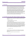
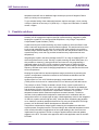
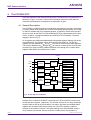
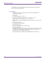
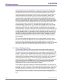
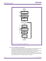
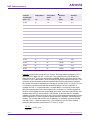
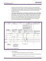
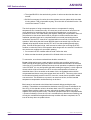
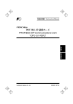
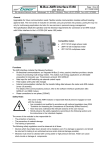
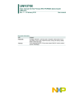
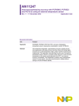
AN10652 Improved timekeeping accuracy with PCF8563 using external temperature sensor Rev. 01.01 — 2 November 2007 Application note Document information Info Content Keywords PCF8563, RTC, Accuracy, Timekeeping, Temperature Sensor, Temperature Compensation, Crystal, 32.768 kHz Abstract The temperature dependent characteristics of quartz crystals prevent time keeping with state-of-the-art real time clocks from being highly accurate over a wide temperature range, unless corrective measures are implemented. This application note describes how the use of an external temperature sensor, placed in a location which will be at or near the same temperature as the quartz crystal attached to the PCF8563 RTC can improve accuracy considerably. If the application is already using a temperature sensor for some reason, all that is needed is some extra firmware without adding to the Bill Of Material (BOM). AN10652 NXP Semiconductors Improved timekeeping accuracy using external temperature sensor Revision history Rev Date Description 01 20071102 First Official Release Contact information For additional information, please visit: http://www.nxp.com For sales office addresses, please send an email to: [email protected] AN10652_1 Application note © NXP B.V. 2007. All rights reserved. Rev. 01.01 — 2 November 2007 2 of 20 AN10652 NXP Semiconductors Improved timekeeping accuracy using external temperature sensor 1. Introduction Real-time clocks (RTC) have been around for a long time and many electronic systems include one for functions like keeping calendar time, tariff switching, time stamping or waking up a system periodically to initiate certain actions, for example doing some measurements. Not all applications need the same level of accuracy, but when high accuracy is necessary like in applications that rely on real time data where accuracy better than 5 ppm is needed, a standard RTC does not fulfil these. Time keeping can only be as accurate as its reference. Several environmental factors like humidity, vibration and pressure can influence RTC-accuracy but it is mainly the inferior characteristics of a quartz crystal over temperature which result in deviations if temperature is changing. Many techniques have been used to improve the timekeeping accuracy achieved using 32.768 kHz crystals. This application note describes how the use of an external temperature sensor, placed in a location which will be at or near the same temperature as the PCF8563 RTC and its crystal can improve accuracy considerably. If the application is already using a temperature sensor, all that is needed is some extra firmware without adding to the Bill Of Material (BOM). 2. The problem when using an RTC without temperature compensation Time keeping can often be done using the built in oscillator in the system microcontroller. In certain situations though, using an RTC is unavoidable. Using an RTC has several benefits: • Low power consumption • Frees the main system for time-critical tasks • Higher timekeeping accuracy However, even when using an RTC the time can only be as accurate as the reference used. A crystal's frequency characteristic depends on the shape or 'cut' of the crystal. A manufacturer can control the crystal turnover frequency by the angle the crystal is cut. However, having to manufacture crystals with different cutting angles adds complexity and cost. A tuning fork crystal is usually cut such that its frequency over temperature is a parabolic curve centered around 25 °C, see Fig 1. This means that a tuning fork crystal oscillator will resonate close to its target frequency at room temperature, but will slow down when the temperature either increases or decreases from room temperature. The frequency of a typical crystal at a specific temperature T is given by: [ f = f 0 1 + B (T − T0 ) 2 ] Here f is the frequency, f0 is the frequency at room temperature, B is the parabolic coefficient, T is the temperature and T0 is the turnover temperature, the top of the parabolic curve. Further f0 can be considered to consist of two components as f 0 = f nom + f off AN10652_1 Application note © NXP B.V. 2007. All rights reserved. Rev. 01.01 — 2 November 2007 3 of 20 AN10652 NXP Semiconductors Improved timekeeping accuracy using external temperature sensor Here fnom is the nominal frequency as specified and foff the offset from this nominal frequency which is a result of production spread, both at room temperature. [ ⎛ f = ⎜⎜ f nom + f off ⎝ ] ⎞ 2 ⎟⎟ ⋅ 1 + B(T − T0 ) ⎠ f − f nom Δf = in ppm, we can now write: For the frequency deviation f nom f nom [ f off Δf 2 2 = B(T − T0 ) + 1 + B(T − T0 ) f nom f nom ] (1) 001aag901 20 frequency deviation Δf/f0 (ppm) −20 ΔT0 32.768 kHz Δfoff −60 −100 −140 −180 −40 −30 −20 −10 0 10 20 30 40 50 60 70 80 T (°C) 90 Fig 1. The deviation in frequency vs temperature of a typical 32.768 kHz crystal In equation (1) above there are three variables that influence the frequency response as a function of temperature. These are the parabolic coefficient B, the turnover temperature T0 and the room temperature offset foff. The crystal manufacturer specifies these parameters and typical values are T0 = 25°C, ∆T0 = ± 5°C and foff = 30ppm. The coefficient B has a very small spread for various crystals of one type, but it has the largest effect on the parabolic nature of the frequency deviation as a function of temperature. Variation in the turnover temperature T0 will shift the deviation curve left or right, variation in the offset at room temperature will shift it up or down. In practice the combination of variation in T0 and offset at room temperature easily results in an accuracy of ±30 ppm at room temperature which equates to a time deviation of around 15 minutes per year. In addition there is the effect of temperature. Typical values for B range from −0.035 ppm/°C² to −0.04 ppm/°C². In a real application, and using B = -0.04 this means that a clock built using a regular 32.768 kHz tuning fork crystal will at room temperature only have the frequency deviation resulting from the variations in T0 and foff, however will lose an additional two minutes per year at 10 degrees Celsius above (or below) room AN10652_1 Application note © NXP B.V. 2007. All rights reserved. Rev. 01.01 — 2 November 2007 4 of 20 AN10652 NXP Semiconductors Improved timekeeping accuracy using external temperature sensor temperature and will lose an additional eight minutes per year at 20 degrees Celsius above (or below) room temperature. To give a better feeling of the relationship between real time and ppm, a clock running 1s/day too fast has an accuracy of 1/(3600*24) = 11.57ppm and a deviation of 1s/week means 1.65ppm. 3. Possible solutions Not many options have been available to improve upon the inaccuracies. Timekeeping accuracy can for example be improved through crystal screening, integrated crystals, keeping the crystal/RTC at a well specified temperature, or by using a Temperature Compensated Crystal Oscillator (TXCO). Crystal screening here means selecting only those crystals for which the offset foff falls within a narrower range than the normal production spread. This would need to be done by the crystal manufacturer, and limits the vertical shift of the parabolic curve within a narrower range. Besides adding to the cost, it does not alter the parabolic nature of the crystal’s frequency curve and only provides a small accuracy improvement at room temperature. Integrating the crystal in the same package as the RTC is a way of supplying RTC’s of which the performance is known. Usually a crystal screening will have taken place. It is also possible to measure foff during production and correct for it by programming a dedicated register in the RTC if such a register is implemented. It makes life for the system designer a bit easier but as the previous option, it does nothing to alleviate the frequency deviation as a result of changing temperatures. It only reduces the initial error at room temperature. Keeping the crystal within a narrow temperature range can be done by mounting the crystal in a temperature-controlled container but this will add considerable cost and complexity to the system. Another option is to use a 32.768 kHz temperature-compensated crystal oscillator (TCXO) as the clock source for a stand-alone RTC but obviously this will add cost too. The principle on which TCXOs are based is simple. Every crystal is optimized for a particular load capacitance. The value of this capacitance is included in the datasheet and deviations from this value will result in a shift in frequency of the oscillator. A TCXO uses this characteristic to implement a compensation mechanism. It includes a temperature sensor which measures temperature at certain intervals. The device includes a lookup table and the temperature measurements in combination with the lookup table result in an output signal to apply a load-capacitance value for the integrated 32.768 kHz crystal to achieve high accuracy. It has the effect of flattening the parabolic curve, ideally to a perfectly straight horizontal line. By using an off-the-shelf TCXO high accuracy can be achieved without development or calibration effort. Temperature compensation always implies measuring the temperature at which the crystal operates, at regular intervals. Then according to the measured temperature some action needs to be taken like adjustment of the crystal loading to the clock source as implemented in conventional TCXOs or using an algorithm which reads and updates registers in the RTC. The latter is the approach used in this application note for the NXP PCF8563. AN10652_1 Application note © NXP B.V. 2007. All rights reserved. Rev. 01.01 — 2 November 2007 5 of 20 AN10652 NXP Semiconductors Improved timekeeping accuracy using external temperature sensor 4. The PCF8563 RTC Since this application note deals specifically with the PCF8563 below an introduction to this device is given. In section 7 some further information about other NXP real-time clocks and implementation of temperature compensation is given. 4.1 General Description The PCF8563 is a CMOS real time clock/calendar optimized for low power consumption. It contains sixteen 8-bit registers with an auto-incrementing address register, an on-chip 32.768 kHz oscillator with one integrated capacitor, a frequency divider which provides the source clock for the Real Time Clock/calendar (RTC), a programmable clock output, a timer, an alarm, a voltage-low detector and a 400 kHz I2C-bus interface. The block diagram is shown in Fig 2. All 16 registers are designed as addressable 8-bit parallel registers although not all bits are implemented. The registers can be both read from and written to. The first two registers (memory address 00HEX and 01HEX) are used as control and/or status registers. The memory addresses 02HEX through 08HEX are used as counters for the clock function (seconds up to years counters). Address locations 09HEX through 0CHEX contain alarm registers which define the conditions for an alarm. CLKOUT 7 OSCI OSCO 1 CONTROL/STATUS 1 0 CONTROL/STATUS 2 1 SECONDS/VL 2 3 MINUTES 3 4 HOURS 4 DAYS 5 WEEKDAYS 6 MONTHS/CENTURY 7 YEARS 8 2 OSCILLATOR 32.768 kHz DIVIDER INT VSS VDD 8 VOLTAGE DETECTOR OSCILLATOR MONITOR SCL SDA POR CONTROL LOGIC 6 5 I2C-BUS INTERFACE ADDRESS REGISTER PCF8563 1 Hz MINUTE ALARM 9 HOUR ALARM A DAY ALARM B WEEKDAY ALARM C CLKOUT CONTROL D TIMER CONTROL E TIMER F mgm662 Fig 2. Block diagram of PCF8563 Address 0DHEX controls the CLKOUT output frequency. 0EHEX and 0FHEX are the timer control and timer registers, respectively. The seconds, minutes, hours, days, weekdays, months, years as well as the minute alarm, hour alarm, day alarm and weekday alarm registers are all coded in BCD format. When one of the RTC registers is read the contents of all counters are frozen. Thus faulty reading of the clock/calendar during a carry condition is prevented, however under the condition that a read operation is AN10652_1 Application note © NXP B.V. 2007. All rights reserved. Rev. 01.01 — 2 November 2007 6 of 20 AN10652 NXP Semiconductors Improved timekeeping accuracy using external temperature sensor completed within 1 second of initiation. Detailed information about this is provided in section 5.3 Step 3; Updating the time. 4.2 Features Provides year, month, day, weekday, hours, minutes and seconds based on a 32.768 kHz quartz crystal. Century flag. Clock operating voltage: 1.8 V to 5.5 V. Low backup current; typical 0.25 µA at VDD = 3.0 V and Tamb = 25 °C. 400 kHz two-wire I2C-bus interface (at VDD = 1.8 V to 5.5 V). Programmable clock output for peripheral devices (32.768 kHz, 1024 Hz, 32 Hz and 1 Hz). Alarm and timer functions. One integrated oscillator capacitor. Internal power-on reset. I2C-bus slave address: read A3HEX and write A2HEX . Open-drain interrupt pin. Electrostatic Discharge (ESD) protection exceeds 2000 V Human Body model (HBM) per JESD22-A114, 200 V Machine Model (MM) per JESD22-A115 and 2000 V Charged Device Model (CDM) per JESD22-C101. Latch-up testing is done to JEDEC standard JESD78 which exceeds 100 mA. AN10652_1 Application note © NXP B.V. 2007. All rights reserved. Rev. 01.01 — 2 November 2007 7 of 20 AN10652 NXP Semiconductors Improved timekeeping accuracy using external temperature sensor 4.3 Register organization Table 1. Register overview Bit positions labelled as x are not implemented. Bit positions labelled with 0 should always be written with logic 0; if read they could be either logic 0 or logic 1. Address Register name Bit 7 Bit 6 Bit 5 Bit 4 Bit 3 Bit 2 Bit 1 Bit 0 00HEX control/status 1 TEST1 0 STOP 0 TESTC 0 0 0 01HEX control/status 2 0 0 0 TI/TP AF TF AIE TIE 02HEX seconds VL <seconds 00 to 59 coded in BCD> 03HEX minutes x <minutes 00 to 59 coded in BCD> 04HEX hours x x <hours 00 to 23 coded in BCD> 05HEX days x x <days 01 to 31 coded in BCD> 06HEX weekdays x x x 07HEX months/century C x x 08HEX years 09HEX minute alarm AE 0AHEX hour alarm AE x <hour alarm 00 to 23 coded in BCD> 0BHEX day alarm AE x <day alarm 01 to 31 coded in BCD> 0CHEX weekday alarm AE x x x x 0DHEX CLKOUT control FE x x x x x FD1 FD0 0EHEX timer control TE x x x x x TD1 TD0 0FHEX timer x x <weekdays 0 to 6> <months 01 to 12 coded in BCD> <years 00 to 99 coded in BCD> <minute alarm 00 to 59 coded in BCD> <weekday alarm 0 to 6> <timer countdown value> For more detailed information about these registers and how to set them, please refer to the PCF8563 datasheet which is available at www.nxp.com. 4.4 Initial calibration In order to achieve highest accuracy it is possible to tune the frequency before any temperature compensation is implemented. Thus it is possible to compensate for variations in T0 and foff in order to ensure that the crystal runs at/near 32.768 kHz at room temperature. The PCF8563 has the option to output the buffered crystal frequency to the pin CLKOUT. Operation is controlled by the CLKOUT control register at address 0DHEX. CLKOUT is an open-drain output and enabled at power-on. If disabled it becomes high-impedance. In order to output the buffered crystal frequency at output CLKOUT, set the register 0DHEX CLKOUT control to 80HEX. The frequency can now be tuned by adjusting the variable capacitor as indicated in Fig 3 below. Note: Touching the adjustment screw often causes the capacitance and thus the frequency to shift. AN10652_1 Application note © NXP B.V. 2007. All rights reserved. Rev. 01.01 — 2 November 2007 8 of 20 AN10652 NXP Semiconductors Improved timekeeping accuracy using external temperature sensor Fig 3. Oscillator tuning If the required accuracy is within 1 second per day you need at least an 8 digit frequency counter with an accuracy of 1 ppm. Here 1 ppm equals 32.768 mHz and thus if the clock is running at a nominal 32.768 kHz: • +1 ppm = 32768.0327 Hz; • -1 ppm = 32767.9673 Hz (1 day has 86400 s, 1s/day = 11.6 ppm). Tune the oscillator at the turnover temperature T0 of the crystal. 5. Procedure to correct time deviations due to varying temperature In order to implement the temperature compensation algorithm described in this application note, a microcontroller (the system microcontroller) as well as an external temperature sensor to measure the ambient temperature is required. The temperature sensor must be located such that the measured temperature is a good representation of the crystal temperature. How often the temperature needs to be measured depends on the application and is a parameter to be chosen by the system designer. The RTC needs to send an interrupt to the microcontroller on regular intervals, telling it to measure the temperature. If it is a low power application where the microcontroller may be in standby, waking up the microcontroller obviously will increase power consumption, so how often this is done is a compromise between accuracy requirements and power consumption. The interval should be chosen such, that the temperature is not expected to change much during the chosen timeframe. A value could be once per minute, or once per five minutes. This method is an approximation of taking the integral over time of the AN10652_1 Application note © NXP B.V. 2007. All rights reserved. Rev. 01.01 — 2 November 2007 9 of 20 AN10652 NXP Semiconductors Improved timekeeping accuracy using external temperature sensor time deviation as a function of temperature. The narrower the time intervals, the better the approximation of the integral will be, but if temperature changes only slowly larger time intervals can be chosen. It is now assumed that the temperature was constant during the past interval and equal to the value measured. This measured temperature is used to calculate the time deviation (in ppm), using a lookup table or equation, that occurred over the interval and the result (the time to be compensated) is stored in a memory location in the system microcontroller. All values calculated for each interval passed are accumulated. Since the internal clock is divided to have internal 1Hz pulses and since the register with the highest resolution in the PCF8563 is the seconds register, it is not possible to execute a compensation when the accumulated value is still in the order of micro seconds or milliseconds. Compensation can only be done once the accumulated value comes close to 1s. (PCF8583 and PCF8593 have a 10ms counter, see section 7 Other NXP real-time clocks.) Since the compensation value that can be written into the RTC will be an integer in seconds, an update must be done when the accumulated value is as close to an integer in seconds as possible. A practical approach would be to update the RTC as soon as the accumulated value exceeds 1s. This is also an easily testable criterion. The algorithm will then compensate the time lost due to the temperature variations by reading the time according to the PCF8563 from its registers, add the accumulated value and write it back into the PCF8563. Hereafter the stored accumulated time (deviation) will be reset to 0 since now the time in the RTC has just been corrected. The flow chart implementing this is given in Fig 4 on the next page. This is not a onetime event, but needs to be repeated every time a temperature measurement needs to be done. In order to implement all steps correctly, details that have to be taken into account for the practical implementation are described in sections 5.1 until 5.3. The steps that need more attention have been indicated in the flow chart with (1), (2) and (3). 5.1 Step 1; Setting the timer The first step is to decide at which intervals the microcontroller should measure the temperature and set the timer accordingly. The 8-bit countdown timer at address 0FHEX can be used for this and is controlled by the timer control register at address 0EHEX, refer to Table 1. The timer control register determines one of 4 source clock frequencies for the timer (4096 Hz, 64 Hz, 1 Hz, or 1/60 Hz), and enables or disables the timer. The timer counts down from a software-loaded 8-bit binary value. At the end of every countdown, the timer sets the Timer Flag (TF). The TF may only be cleared by software. The asserted TF can be used to generate an interrupt (INT). The interrupt may be generated as a pulsed signal every countdown period or as a permanently active signal which follows the condition of TF. Bit TI/TP is used to control this mode selection. When reading the timer, the current countdown value is returned. If we would like to generate, based on the example described before, an interrupt to the microcontroller every 5 minutes, the timer control register at address 0EHEX would have to be loaded with 83HEX. This sets bit 7 TE to enable the timer and it sets bits 1 and 0 (TD1 and TD0) to select source clock frequency 1/60 Hz which results in a clock giving one pulse per minute. The value written to the timer countdown register at address 0FHEX represents then the interval in minutes. In this case it would have to be programmed with 05HEX. AN10652_1 Application note © NXP B.V. 2007. All rights reserved. Rev. 01.01 — 2 November 2007 10 of 20 AN10652 NXP Semiconductors Improved timekeeping accuracy using external temperature sensor START (1) (2) Send INT to uC to measure temperature (every x mins) Determine time deviation resulting from measured temperature and interval Add time deviation to accumulated value TAcc in uC memory Tacc > 1 s? N Y Read Time TRTC from RTC (3) Add accumulated deviation to RTC time TRTC = TRTC + TAcc Write new value TRTC in PCF8563 registers Reset accumulated deviation TAcc = 0 STOP Fig 4. Flow chart of procedure to update the time 5.2 Step 2; Find the time deviation In order to find the time deviation that must be compensated, a lookup table or a second order equation (parabola) derived from measurements done can be used. This table/equation should contain the deviation in ppm relative to the nominal conditions and is specific for the crystal used. If the type of crystal is changed, a new lookup table/equation is necessary. This correction method uses no feedback, so it is important to have a precise table or equation since any errors in this input will result in errors in the compensation values. How to create such a table or equation? AN10652_1 Application note © NXP B.V. 2007. All rights reserved. Rev. 01.01 — 2 November 2007 11 of 20 AN10652 NXP Semiconductors Improved timekeeping accuracy using external temperature sensor If the datasheet of the crystal used incorporates the parabolic curve and a table with these deviations, this can be used under the condition that the resolution of the data is high enough. Otherwise a high resolution frequency counter is necessary to measure and record how long a nominal 1s period out of the RTC actually takes when the crystal/RTC combination is subject to varying temperatures. In order to cover the whole temperature range for which the PCF8563 is specified, measurements should be done from -40 °C to 85 °C. It is time consuming, but more reliable than attaching the frequency meter to the OSCO pin which would add capacitance to this pin and thus detune the frequency with a delta f that has to be compensated as well. After the data has been collected it can be input into an Excel spreadsheet from where the equation can be generated. A less time consuming method is to use the second order equation and the value for B given in the crystal’s datasheet. The production spread of B for a certain type of crystal is small. From formula (1) on page 4 the frequency deviation for a given temperature follows and from there the correction value can be calculated. The microcontroller could calculate the deviation from this equation and the temperature measured. Alternatively the designer can create a lookup table from which the deviations are read. Below such a lookup table is given for a crystal with B = −0.035 ppm/°C² and T0 = 25 °C for temperatures from -40 °C to +85 °C in steps of 5 °C. Tolerances in T0 and foff have not been taken into account and thus the formula used to calculate ∆f/f in Table 2 reduces to equation (2) below. For the lookup table, only columns 2 and 4 are relevant. Δf 2 = B(T − T0 ) f nom (2) Table 2. Example Lookup Table Only columns 2 and 4 (Temperature T and resulting ∆f/f in ppm) need to be included Parabolic Coefficient B Temperature T Temperature Offset Deviation Deviation ∆f/f ∆f/f [ppm / °C2] [°C] [°C] [ppm] [Hz] -0.035 -40 -65 -147.88 -4.85 -0.035 -35 -60 -126.00 -4.13 -0.035 -30 -55 -105.88 -3.47 -0.035 -25 -50 -87.50 -2.87 -0.035 -20 -45 -70.88 -2.32 -0.035 -15 -40 -56.00 -1.84 -0.035 -10 -35 -42.88 -1.40 -0.035 -5 -30 -31.50 -1.03 -0.035 0 -25 -21.88 -0.72 -0.035 5 -20 -14.00 -0.46 -0.035 10 -15 -7.88 -0.26 AN10652_1 Application note © NXP B.V. 2007. All rights reserved. Rev. 01.01 — 2 November 2007 12 of 20 AN10652 NXP Semiconductors Improved timekeeping accuracy using external temperature sensor Parabolic Coefficient B Temperature T Temperature Offset Deviation Deviation ∆f/f ∆f/f [ppm] [Hz] [ppm / °C2] [°C] [°C] -0.035 15 -10 -3.50 -0.11 -0.035 20 -5 -0.88 -0.03 -0.035 25 0 0.00 0.00 -0.035 30 5 -0.88 -0.03 -0.035 35 10 -3.50 -0.11 -0.035 40 15 -7.88 -0.26 -0.035 45 20 -14.00 -0.46 -0.035 50 25 -21.88 -0.72 -0.035 55 30 -31.50 -1.03 -0.035 60 35 -42.88 -1.40 -0.035 65 40 -56.00 -1.84 -0.035 70 45 -70.88 -2.32 -0.035 75 50 -87.50 -2.87 -0.035 80 55 -105.88 -3.47 -0.035 85 60 -126.00 -4.13 -0.035 90 65 -147.88 -4.88 Example: Suppose the interval time is 5 minutes. The temperature measured is +45 °C. According to the table now ∆f/f = -14.00 ppm. The crystal frequency has slowed and (after division by 215) is not 1Hz anymore but 0.999986. Now the 1Hz clock period does not take 1s, but 1.0000140002 s. Every second time lags by an additional 0.014 ms. The corrective value to be added to the accumulated value for this measurement would be the number of seconds multiplied by the time lag per second: (5*60) * 0.014 ms = 4.2 ms. For simplicity we now assume that the ambient temperature for the crystal/RTC is constant and +45 °C. In that case every 5 minutes adds 4.2 ms time lag, and it would take 239 measurements for the accumulated value to exceed 1 s. Now the registers in the RTC will be updated and the accumulated value reset. A day has 1440 minutes, 239 measurements every 5 minutes equals 1195 minutes. In this case the RTC would be updated a bit more often than once per day. The more the temperature deviates from the room temperature, the more frequent an update would be necessary. Still a small error remains. The moment that the RTC time is shifted by 1s (updated), the actual time lag was 239*4.2 ms = 1.0038 seconds. Every 1195 minutes an error of 3.8 ms remains (excluding the production spread errors in T0 and foff ). In ppm: 3.8 ⋅10 −3 = 0.053 ppm 1195 ⋅ 60 AN10652_1 Application note © NXP B.V. 2007. All rights reserved. Rev. 01.01 — 2 November 2007 13 of 20 AN10652 NXP Semiconductors Improved timekeeping accuracy using external temperature sensor This is not meant to claim that this degree of accuracy can be achieved. There will be errors in the measurements, there will be the production spread of the crystals. In this theoretical example though the deviation as a function of temperature was reduced from 14.00 ppm to 0.053 ppm and in a practical situation a considerable improvement can be achieved as well. 5.3 Step 3; Updating the time It is necessary for correct time keeping that a read operation from the PCF8563 or a write operation into the PCF8563 is finished within one second of initiating it. The datasheet from the PCF8563 states “When one of the RTC registers is read the contents of all counters are frozen. Therefore faulty reading of the clock/calendar during a carry condition is prevented.” But what does this mean exactly and why is this necessary? In Fig 5 a block diagram representing some blocks in the PCF8563 has been drawn and in Fig 6 a sequence of events is given when a read operation starts. This signal stops the time counters from counting. It is generated when an I2C READ or WRITE is initiated. I2C interface BLOCK Time counters SDA 64Hz SCL Pre-scaler 1Hz clocks clock reset Watchdog I2C watchdog (active low) This signal resets the I2C interface if BLOCK remains active for too long. Fig 5. Block diagram I2C interface and Time counters When there is no I2C activity the RTC is counting normally. Once an I2C read or write operation is initiated, the I2C interface asserts the signal BLOCK. This signal stops the time counters (registers 02HEX to 08HEX ) from counting. Further this results in the watchdog no longer being reset. At the next rising edge of the 1 Hz clock, time does not AN10652_1 Application note © NXP B.V. 2007. All rights reserved. Rev. 01.01 — 2 November 2007 14 of 20 AN10652 NXP Semiconductors Improved timekeeping accuracy using external temperature sensor increment because the registers have been frozen. However, the watchdog counter increments now. Thus the increase in time is recorded and after the read operation has completed BLOCK goes low again. Now the stored clock in the watchdog is used to give an extra pulse to the time counters to make sure that correct time is kept. Also the watchdog will be reset. The maximum watchdog value is 2. If at the second rising edge of the 1 Hz clock after a read operation was initiated, the reading operation has not been completed yet, BLOCK will still be high. The time counters don’t increase and the watchdog counter increases and reaches its maximum value. Its output is set active which resets the I2C interface which in turn resets the BLOCK signal. Again one pulse (not two) is send to the time counters and the watchdog is reset. But now two rising edges of the 1Hz clock didn’t reach the time counters and only one was compensated for. The RTC looses one second. The exact sequence of events is depicted below. Fig 6. Sequence of events (example READ) From this follows: • A I2C read must be terminated within one second of initiation; • The RTC will automatically terminate the read if it remains active for longer than one second; • Each time auto termination occurs, the RTC looses one second; AN10652_1 Application note © NXP B.V. 2007. All rights reserved. Rev. 01.01 — 2 November 2007 15 of 20 AN10652 NXP Semiconductors Improved timekeeping accuracy using external temperature sensor • The signal BLOCK is also active during a write. A write must also last less than one second; • BLOCK is necessary for a write since the registers must not update whilst new data is being written. That is impossible anyway, since the clock is switched from the 1 Hz clock to the internal I2C clock. The whole purpose of using a temperature sensor to compensate for varying temperatures is to increase accuracy. Of course we would not want to introduce even more deviations by exceeding this one second limit. Besides that, in order for the procedure to work, in this case reading the registers, adding the compensation value to it (this will also be one second but this has in principle no relation with the fact that a read/write operation needs to be completed within one second) and writing the new values back into the RTC must all be completed within one second of initiating the read operation. While doing that the internal BLOCK signal must remain high until the new updated value has been written into the RTC to be sure that updating actually takes place. If the BLOCK signal is high, it will become low either upon receiving the STOP condition or when the read or write operation takes longer than one second. From this we can see the two conditions for successful updating: 1. Do not send a STOP condition after the read / before the write; 2. Make sure that the whole operation will be finished within one second. To summarize, once the accumulated time deviation exceeds 1s: Do not: Initiate and execute a read operation, send the stop condition (which would result in the BLOCK signal going low), add the accumulated time deviation as indicated in the flow of Fig 4 and then initiate and execute a write operation to update the registers in the PCF8563. It is very well possible that while reading the registers, a clock edge was missed, which will be corrected in the RTC once the read operation is finished, as described above. Since we would not be aware of this, the outdated value would be compensated and thus a wrong value written back into the RTC. This wrong value would be the same as already present in the RTC since the ‘counter freeze operation’ added one second too. This would thus not result in an extra loss of time, but the intended temperature compensation would effectively not be done. Do: Instead, a read needs to be initiated and executed without sending the stop condition. Then add the accumulated time deviation to the RTC time as indicated in the flow of Fig 4. Now that the values to be written back in the RTC registers are known, a repeated start condition needs to be sent, after which the data is written in the RTC registers and a stop condition is sent. This whole operation needs to be completed within 1 second of initiating it. Since the I2C bus is considered busy after the start condition, and will only be considered free again after the stop condition has been completed, the I2C bus will be busy when an update is done. AN10652_1 Application note © NXP B.V. 2007. All rights reserved. Rev. 01.01 — 2 November 2007 16 of 20 AN10652 NXP Semiconductors Improved timekeeping accuracy using external temperature sensor 6. NXP Demonstration board kit I2C 2005-1 A fast way to start developing an algorithm and test its working is possible using the NXP I2C demonstration board kit I2C 2005-1. This includes a PCB populated with I2C devices, power supplies, connectors, and LEDs. The kit contains a USB cable and, via download, a copy of Win-I2CUSB Lite software can be obtained. The board has twelve generalpurpose I2C logic devices in the following categories: I/O expander, LED blinker, LED dimmer, EEPROM, temperature sensor, real-time clock, multiplexer, switch, and bus master selector. The board’s hardware connects to the USB port of a PC and uses the I2C protocol to provide bi-directional communications with the I2C devices. Power is provided by the PC’s USB port, so there is no need for an additional external power supply. The real-time clock present on the board is the PCF8563TD, the temperature sensor is the SA56004ED. With both the RTC and temperature sensor onboard, it is easy to start developing your application and implementing the algorithm as described here. 7. Other NXP Real-time clocks This application note deals specifically with the PCF8563 RTC but can with small modifications also be used as a guideline to implement an algorithm to compensate for varying temperatures when other NXP real-time clocks are used. Designed for a range of demanding applications, these real-time clocks/calendars are driven by a low-power 32.768 kHz quartz oscillator, use the SPI or I2C-bus for serial data transfer and typically consume less than 1 μW of power. This means that all these RTCs can be powered by a very small battery or a small super-cap. The RTCs most similar to the PCF8563 are PCA8565, PCF8583 and PCF8593. Besides this range the product line includes the PCA2125 and will soon be extended with PCF2124 and PCF2128 (release end of 2007). Thus the product line includes the following: • PCF8563 with I2C interface for low-power applications • PCA8565 with I2C interface for high-temperature applications • PCF8583 with I2C interface, 10 ms resolution where additional scratch pad RAM is required • PCF8593 with I2C interface and 10 ms resolution • PCF2124 with SPI interface for low-power applications • PCA2125 with SPI interface for high-temperature applications • PCA2128 with I2C and SPI interface, TCXO with high accuracy Addresses and data are transferred serially via an SPI bus with a maximum speed of 7.0 Mbps (PCF2124, PCA2125) or via a two-line, bidirectional I2C-bus that operates at a maximum speed of 400 kbps (PCF8563 and PCA8565) or 100 kbps (PCF8583). The PCF2128 contains both a SPI- and an I2C interface. The built-in word address register is incremented automatically after each data byte is written or read. AN10652_1 Application note © NXP B.V. 2007. All rights reserved. Rev. 01.01 — 2 November 2007 17 of 20 AN10652 NXP Semiconductors Improved timekeeping accuracy using external temperature sensor With the PCF8583, the address pin A0 is used to program the software address, so two devices can be connected to the bus without additional hardware. Each RTC has an internal power-on reset and a programmable clock output with open drain configuration to drive peripheral devices. A low-voltage detector (not included on the PCF8583 and PCF8593) ensures the integrity of all clock functions. Power consumption is kept to a minimum in all the devices. The PCF2124 and PCF8563 are optimized for battery-powered applications and consume as little as 250 nA at 3 V. The PCA8565 and PCA2125 oscillator operates over a wider temperature range (125 ºC maximum) and is suitable for use in the harsh environments found within automobiles. Power consumption remains low — only 700 nA at 2 V. The requirement that read and write operations to the device need to be finalized within one second of initiating, is valid for all these devices too. For applications where very accurate time keeping is necessary the PCF2128 is a CMOS real time clock/calendar with an integrated temperature compensated crystal oscillator (TCXO) and a 32.768 kHz quartz crystal optimized for very high accuracy and very low power consumption. The PCF2128 has 512 bytes of general purpose static RAM, a selectable I2C and SPI interface, a backup battery switch-over circuit, a programmable watchdog function, a timestamp function and many other features. Obviously implementation of the procedure described in this application note does not apply to the PCF2128. 8. References The documents listed below provide further useful information. They are available at NXP’s website www.nxp.com. 1. Product data sheet PCF8563. 2. AN_pcf8563-73-83-93_real_time_clock; Application Note for the Real Time Clocks PCF8563,73,83,93. September 1, 1999. 3. UM10204_3; I2C-bus specification and user manual. Rev 3, 19 June 2007. AN10652_1 Application note © NXP B.V. 2007. All rights reserved. Rev. 01.01 — 2 November 2007 18 of 20 AN10652 NXP Semiconductors Improved timekeeping accuracy using external temperature sensor 9. Legal information 9.1 Definitions Draft — The document is a draft version only. The content is still under internal review and subject to formal approval, which may result in modifications or additions. NXP Semiconductors does not give any representations or warranties as to the accuracy or completeness of information included herein and shall have no liability for the consequences of use of such information. 9.2 Disclaimers General — Information in this document is believed to be accurate and reliable. However, NXP Semiconductors does not give any representations or warranties, expressed or implied, as to the accuracy or completeness of such information and shall have no liability for the consequences of use of such information. Right to make changes — NXP Semiconductors reserves the right to make changes to information published in this document, including without limitation specifications and product descriptions, at any time and without notice. This document supersedes and replaces all information supplied prior to the publication hereof. Suitability for use — NXP Semiconductors products are not designed, authorized or warranted to be suitable for use in medical, military, aircraft, space or life support equipment, nor in applications where failure or malfunction of a NXP Semiconductors product can reasonably be expected to result in personal injury, death or severe property or environmental damage. NXP Semiconductors accepts no liability for inclusion and/or use of NXP Semiconductors products in such equipment or applications and therefore such inclusion and/or use is for the customer’s own risk. Applications — Applications that are described herein for any of these products are for illustrative purposes only. NXP Semiconductors makes no representation or warranty that such applications will be suitable for the specified use without further testing or modification. 9.3 Trademarks Notice: All referenced brands, product names, service names and trademarks are property of their respective owners. AN10652_1 Application note © NXP B.V. 2007. All rights reserved. Rev. 01.01 — 2 November 2007 19 of 20 AN10652 NXP Semiconductors Improved timekeeping accuracy using external temperature sensor 10. Contents 1. 2. 3. 4. 4.1 4.2 4.3 4.4 5. 5.1 5.2 5.3 6. 7. 8. 9. 9.1 9.2 9.3 10. Introduction .........................................................3 The problem when using an RTC without temperature compensation ................................3 Possible solutions...............................................5 The PCF8563 RTC ...............................................6 General Description ...........................................6 Features .............................................................7 Register organization .........................................8 Initial calibration .................................................8 Procedure to correct time deviations due to varying temperature............................................9 Step 1; Setting the timer...................................10 Step 2; Find the time deviation.........................11 Step 3; Updating the time.................................14 NXP Demonstration board kit I2C 2005-1.........17 Other NXP Real-time clocks .............................17 References .........................................................18 Legal information ..............................................19 Definitions ........................................................19 Disclaimers.......................................................19 Trademarks ......................................................19 Contents.............................................................20 Please be aware that important notices concerning this document and the product(s) described herein, have been included in the section 'Legal information'. © NXP B.V. 2007. All rights reserved. For more information, please visit: http://www.nxp.com For sales office addresses, email to: [email protected] Date of release: 2 November 2007 Document identifier: AN10652_1