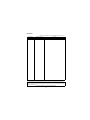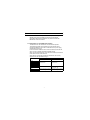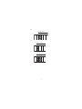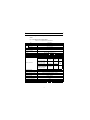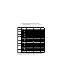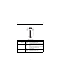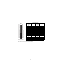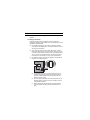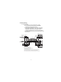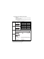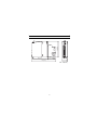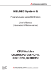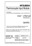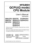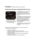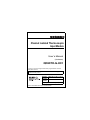
1
Channel Isolated Thermocouple
Input Module
User’s Manual
(Hardware)
QD68TD-G-H01
Thank you for purchasing the Mitsubishi programmable controller
MELSEC-Q series.
Prior to use, please read this and relevant manuals thorougly to fully
understand the product.
MODEL Q68TD-G-H01-U-HW
MODEL
13JY36
CODE
IB(NA)-0800389-A(0707)MEE
© 2007 MITSUBISHI ELECTRIC CORPORATION
SAFETY PRECAUTIONS
(Read these precautions before use.)
Before using this product, please read this manual and the relevant manuals
introduced in this manual carefully and pay full attention to safety to handle the
product correctly.
The instructions given in this manual are concerned with this product. For the
safety instructions of the programmable controller system, please read the User’s
Manual for the CPU module.
In this section, the safety precautions are ranked as "DANGER" and "CAUTION".
DANGER
Indicates that incorrect handling may cause
hazardous conditions, resulting in death or severe
injury.
CAUTION
Indicates that incorrect handling may cause
hazardous conditions, resulting in medium or slight
personal injury or physical damage.
Note that the
CAUTION level may lead to a serious consequence according
to the circumstances.
Always follow the precautions of both levels because they are important to
personal safety.
Please keep this manual accessible when required and always forward it to the
end user.
[DESIGN PRECAUTIONS]
DANGER
Do not write data into the "system area" of the buffer memory of intelligent
function modules. Also, do not use any "prohibited to use" signals as an
output signal to an intelligent function module from the programmable
controller CPU.
Writing data into the "system area" or outputting a signal for "prohibited to
use" may cause a programmable controller system malfunction.
A-1
CAUTION
Do not bunch the control wires or communication cables with the main circuit
or power wires, or install them close to each other.
They should be installed 100 mm (3.94 inch) or more from each other.
Not doing so could result in noise that may cause malfunction.
[INSTALLATION PRECAUTIONS]
CAUTION
Use the programmable controller in the environment conditions given in the
general specifications in the User's Manual for the CPU module. Failure to do
so may cause an electric shock, fire, malfunction, or damage to or
deterioration of the product.
While pressing the installation lever located at the bottom of the module, fully
insert the module fixing projection into the fixing hole in the base unit to
mount the module. Incorrect module mounting may cause a malfunction,
failure, or drop of the module. In an environment of frequent vibrations or
impacts, secure the module with screws.
The screws must be tightened within the specified torque range. If the screw
is too loose, it may cause a drop or malfunction. Excessive tightening may
damage the screw and/or the module, resulting in a drop or malfunction.
Be sure to shut off all phases of the external power supply used by the
system before mounting or removing the module. Failure to do so may cause
damage to the product.
Do not directly touch any conductive part or electronic part of the module.
Doing so may cause a malfunction or failure of the module.
A-2
[WIRING PRECAUTIONS]
CAUTION
Always ground the shielded cables for the programmable controller.
There is a risk of electric shock or malfunction.
For wiring and connection, properly press, crimp or solder the connector with
the tools specified by the manufactures and attach the connector to the
module securely.
Be careful to prevent foreign matter such as dust or wire chips from entering
the module.
Failure to do so may cause a fire, failure or malfunction.
A protective film is attached to the module top to prevent foreign matter such
as wire chips from entering the module during wiring.
Do not remove the film during wiring.
Be sure to remove it for heat dissipation before system operation.
Be sure to place the cables connected to the module in a duct or clamp them.
If not, dangling cables may swing or inadvertently be pulled, resulting in
damage to the module and/or cables, or malfunctions due to poor cable
connection.
When disconnecting the external wiring cable connected to the module, do
not pull it by holding the cable part. Disconnect the cable with connector with
holding the connector plugged into the module. Pulling the cable part with the
cable still connected to the module may cause a malfunction or damage to
the module and/or cable.
Always place the thermocouple at least 100mm (3.94inch) away from the
main circuit cables and AC control lines. Fully keep it away from highvoltage
cables and circuits, which include high frequency waves, such as an
inverter's load circuit. Not doing so will cause the module more susceptible to
noises, surges and inductions.
Do not place a module near the equipment that generates magnetic noise.
A-3
Revisions
* The manual number is given on the bottom right of the cover.
Print Date
Jul., 2007
*Manual Number
IB(NA)-0800389-A
Revision
First edition
This manual confers no industrial property rights or any rights of any other kind, nor does it
confer any patent licenses. Mitsubishi Electric Corporation cannot be held responsible for any
problems involving industrial property rights which may occur as a result of using the contents
noted in this manual.
© 2007 MITSUBISHI ELECTRIC CORPORATION
A-4
CONTENTS
1. OVERVIEW .................................................................................................... 1
1.1 Restrictions on mountable slot position .................................................... 1
2. PERFORMANCE SPECIFICATIONS ............................................................. 3
3. IMPLEMENTATION AND INSTALLATION..................................................... 6
3.1 Handling Precautions ............................................................................... 6
3.2 Installation Environment ........................................................................... 6
4. PART NAMES ................................................................................................ 7
5. WIRING .......................................................................................................... 9
5.1 Wiring Precautions ................................................................................... 9
5.2 External Wiring ....................................................................................... 10
5.3 Intelligent Function Module Switch Settings ........................................... 11
6. EXTERNAL DIMENSIONS ........................................................................... 12
A-5
Manual
The following manual is also related to this product.
Order it if necessary.
Related manual
Manual No.
(Model code)
Manual name
Channel Isolated Thermocouple Input Module
Q68TD-G-H01/GX Configurator-TI (SW1D5C-QTIU)
SH-080699ENG
(13JZ04)
Compliance with the EMC and Low Voltage Directives
When incorporating the Mitsubishi programmable controller into other
machinery or system and ensuring compliance with the EMC and Low
Voltage Directives, refer to Chapter 3 "EMC and Low Voltage Directive"
of the User's Manual (Hardware) for the CPU module. The CE logo is
printed on the rating plate of the programmable controller, indicating
compliance with the EMC and Low Voltage Directives.
In addition, to make the product comply with the EMC and Low Voltage
Directives, refer to Section 5.1 "Wiring Precautions".
A-6
1. OVERVIEW
This manual describes the specifications and part names of type
Q68TD-G-H01 Channel Isolated Thermocouple Input Module
(hereinafter abbreviated as Q68TD-G-H01) that is used with the
MELSEC-Q series CPU module.
1.1 Restrictions on mountable slot position
The Q68TD-G-H01 has restrictions on mountable slot position.
The following describes the restrictions of the slot position when
mounting the Q68TD-G-H01 with a combination of the power supply
module and the base unit.
For the slot that the Q68TD-G-H01 cannot be mounted, leave the slot
open or mount a module other than the Q68TD-G-H01.
When using the Q68TD-G-H01 on the remote I/O station, the restriction
is the same as for the main base unit.
When failing to comply with the following restrictions, the accuracy
might not be in the specification range.
Power supply module
Q61SP
Q61P-A1
Q61P-A2
Q61P
Q62P
Q63P
Q63RP
Q64P
Q64RP
Main base unit
No restrictions
Restrictions
Extension base unit
No restrictions
Mount the module to I/O slot
No.1 or later. (b)
Mount the module to I/O slot Mount the module to I/O slot
No.1 or later. (a)
No.2 or later. (c)
No restrictions
1
(a)
Not mountable
Slot
No.0
Power
supply
Mountable
Slot
No.1
Slot
No.2
CPU
(b)
Not mountable
Slot
No.0
Mountable
Slot
No.1
Slot
No.2
Power
supply
(c)
Not mountable
Mountable
Slot
No.0
Slot
No.2
Slot
No.1
Power
supply
2
2. PERFORMANCE SPECIFICATIONS
The following table shows the performance specifications of the Q68TDG-H01.
(1) List of Performance Specifications
Table 2.1 List of performance specifications
Item
Number of channels
Temperature
Output conversion value
Scaling value
Standard with which
thermocouple conforms
Usable thermocouples and
conversion accuracies
Cold junction temperature
compensation accuracy
Accuracy
Resolution
Conversion speed
Number of analog input points
Specifications
8 channels
16-bit signed binary (-2700 to 18200)
16-bit signed binary
JIS C1602-1995,IEC 60584-1(1995),IEC60584-2(1982)
Refer to (2)
1.0
Depends on the formula listed in *1
B,R,S,N : 0.3
K,E,J,T : 0.1
320ms/8 channels *2
8 channels + cold junction temperature compensation channel/module
Specific isolated area
Isolation specifications
Wire break detection
Maximum number of writes for
Flash memory
Number of I/O points occupied
External wiring connection
system
Applicable wire size
External device connection
connector (option)
Internal current consumption
(5 VDC)
Weight
Outline dimensions
Between thermocouple
input and programmable
controller power supply
Between thermocouple
input channels
Between cold junction
temperature compensation
channel and programmable
controller power supply
Isolation
method
Dielectric
withstand
voltage
Transformer
isolation
500VACrms
for 1min.
Transformer
isolation
1000VACrms
for 1min.
No insulation
-
Not available *3
50,000
16 points (I/O assignment:Intelligent 16 points)
40-pin connector
0.3mm2 (AWG#22)
A6CON4
0.49A
98(H)
3
0.16kg
27.4(W) 90(D)mm
Isolation
resistance
500VDC
10M
or more
-
*1 Calculate the accuracy in the following method.
(Accuracy) = (conversion accuracy) + (temperature characteristic) (operating ambient temperature variation) +
(cold junction temperature compensation accuracy)
An operating ambient temperature variation indicates a deviation of the operating ambient temperature from the
25
5
range.
Example: When using the thermocouple B (refer to (2)) with the operating ambient temperature of 35
measured temperature of 1000
and the
, the accuracy is as follows.
( 2.5 )+( 0.4 ) (35 -30 )+( 1 )= 5.5
*2 The conversion speed is a period that a temperature measurement value is stored into the buffer memory during
sampling processing. Regardless of the number of conversion-enabled channels, a temperature measurement
value is stored into the buffer memory every 320ms. In addition, storing a temperature measurement value into
the buffer memory is executed on every channel one by one.
*3 The Q68TD-G-H01 does not have the wire break detection function. However, the disconnection monitoring
function is available to select a measured temperature value on a disconnection occurrence from either "Up
scale (the maximum value of measured temperature range + 5% of measured temperature range)", "Down scale
(the minimum value of measured temperature range - 5% of measured temperature range)", or "Given value".
Checking a disconnection status takes up to 11s.
4
(2) Usable Thermocouples and Conversion Accuracies
The following table explains the usable thermocouples and
conversion accuracies.
Table2.2 Usable thermocouples and conversion accuracies
Usable
Thermo couple
Type
Measured Temperature
Range*1
0 to 600
B
R
S
Temperature Characteristic
(Per operating ambient
temperature variation of 1 )
Max. Temperature
Error at Ambient
Temperature 55
----- *3
----- *3
----- *3
600 to 800
*2
3.0
800 to 1700
*2
2.5
0.4
13.0
12.5
1700 to 1820
----- *3
----- *3
----- *3
-50 to 0
----- *3
----- *3
----- *3
0 to 300
*2
2.5
*2
300 to 1600
0.4
12.5
2.0
0.3
9.5
1600 to 1760
----- *3
----- *3
----- *3
-50 to 0
----- *3
----- *3
----- *3
0 to 300
*2
2.5
*2
300 to 1600
0.4
12.5
2.0
0.3
9.5
1600 to 1760
----- *3
----- *3
----- *3
-270 to -200
----- *3
----- *3
----- *3
-200 to 0
*2
Larger value of 0.5
and
0.5% of measured temperature
Larger value of 0.06
and
0.2% of measured temperature
0 to 1200
*2
Larger value of 0.25
and
0.5% of measured temperature
Larger value of 0.06
and
0.02% of measured temperature
K
11.0
9.0
1200 to 1370
----- *3
----- *3
----- *3
-270 to -200
----- *3
----- *3
----- *3
-200 to 0
*2
Larger value of 0.5
and
0.5% of measured temperature
Larger value of 0.06
and
0.15% of measured temperature
8.5
0 to 900
*2
Larger value of 0.5
and
0.25% of measured temperature
Larger value of 0.06
and
0.02% of measured temperature
6.75
E
900 to 1000
----- *3
-210 to -40
J
Conversion Accuracy
(At operating ambient temperature
25 5 )
----- *3
*2
-40 to 750
750 to 1200
Larger value of 0.5
and
0.25% of measured temperature
----- *3
-270 to -200
----- *3
----- *3
----- *3
----- *3
----- *3
Larger value of 0.06
and
0.02% of measured temperature
5.625
----- *3
----- *3
----- *3
----- *3
-200 to 0
*2
Larger value of 0.5
and
0.5% of measured temperature
Larger value of 0.06
and
0.1% of measured temperature
6.0
0 to 350
*2
Larger value of 0.5
and
0.25% of measured temperature
Larger value of 0.06
and
0.02% of measured temperature
2.625
-200 to 0
*2
Larger value of 0.5
and
0.5% of measured temperature
Larger value of 0.06
and
0.2% of measured temperature
11.0
0 to 1250
*2
Larger value of 0.5
and
0.25% of measured temperature
Larger value of 0.06
and
0.02% of measured temperature
9.375
T
350 to 400
----- *3
-270 to -200
----- *3
N
1250 to 1300
----- *3
----- *3
----- *3
----- *3
----- *3
----- *3
----- *3
*1 If a value entered from the thermocouple is outside the measured temperature range given in the table, it is
handled as the maximum/minimum value of the measured temperature range.
*2 The accuracies only in the temperature ranges of Class 1 to 3 (shaded areas) in JIS C1602-1995 apply.
*3 Temperature measurement can be executed, but accuracy is not guaranteed.
5
3. IMPLEMENTATION AND INSTALLATION
3.1 Handling Precautions
(1) Do not drop or give a strong impact to the case.
(2) Do not remove the printed-circuit board of the module from the
case.
Doing so may cause a failure.
(3) Be careful to prevent foreign matters such as cutting chips or wire
chips from entering the module.
Failure to do so may cause a fire, failure or malfunction.
(4) A protective film is attached to the module top to prevent foreign
matter such as wire chips from entering the module during wiring.
Do not remove the film during wiring.
Be sure to remove it for heat dissipation before system operation.
(5) Tighten the module fixing screws with the specified torque shown
below.
Insufficient tightening torque could result in short, failure or
malfunction.
Table3.1 Tightening torque
Screw location
Module fixing screw (M3)
Connector fixing screw (M2.6 screw)
Tightening torque range
0.36 to 0.48N•m
0.20N•m
(6) When mounting the module to the base unit, insert the module
fixing projection into the fixing hole in the base unit, and mount the
module with using the hole as a supporting point.
Incorrect module mounting may cause a malfunction, failure, or
drop of the module.
(7) Always make sure to touch the grounded metal to discharge the
electricity charged in the body, etc., before touching the module.
Failure to do so may cause a failure or malfunctions of the module.
3.2 Installation Environment
Refer to the user's manual of the CPU module used.
6
4. PART NAMES
The following explains the part names of the Q68TD-G-H01.
1)
3)
2)
(Connector
terminal
number)
A1
(Connector
terminal
number)
B1
A20
B20
Table4.1 Part names
Number
Name
1)
RUN LED
2)
ERR. LED
3)
ALM LED
Description
Displays the operating status of the Q68TD-G-H01.
On
: Normal operation
Flashing : During offset/gain setting mode
Off
: 5V power supply interrupted, watchdog timer error
occurred, or online module change enabled.
Displays the error status of the Q68TD-G-H01.
On
: Error
Flashing : Error in switch settings
Switch No. 5 of the intelligent function module has
been set to a value other than zero.
Off
: Normal operation
Displays the warning status of the Q68TD-G-H01.
On
:Warning (process alarm, rate alarm) occurring
Flashing :Checking a disconnection status
Off
:Normal operation
7
Table4.2 Signal name
A1
A2
A3
A4
A5
A6
A7
A8
A9
A10
A11
A12
A13
A14
A15
A16
A17
A18
A19
A20
B1
B2
B3
B4
B5
B6
B7
B8
B9
B10
B11
B12
B13
B14
B15
B16
B17
B18
B19
B20
Seen from the front
of the module
Terminal
number
A1
A2
A3
A4
A5
A6
A7
A8
A9
A10
A11
A12
A13
A14
A15
A16
A17
A18
A19
A20
Signal name
CH1+
--CH2+
--CH3+
--CH4+
--CH5+
--CH6+
--CH7+
--CH8+
--------RTDG
*For actual wiring, refer to Section 5.2 External Wiring.
8
Terminal
number
B1
B2
B3
B4
B5
B6
B7
B8
B9
B10
B11
B12
B13
B14
B15
B16
B17
B18
B19
B20
Signal name
CH1--CH2--CH3--CH4--CH5--CH6--CH7--CH8------RTD+
RTD-
5. WIRING
The following explains the wiring precautions and module connection
example.
5.1 Wiring Precautions
External wiring that is less susceptible to noise is required as a
condition of enabling a highly reliable system and making full use of the
capabilities of Q68TD-G-H01.
(1) Use separate cables for the AC control circuit and the external
input signals of the Q68TD-G-H01 to avoid the influence of the AC
side surges and inductions.
(2) Always place the thermocouple at least 100mm away from the
main circuit cables and AC control circuit lines. Fully keep it away
from high-voltage cables and circuits, which include high frequency
waves, such as an inverter's load circuit. Not doing so will cause
the module more susceptible to noises, surges and inductions.
(3) The following wiring is required for the product to comply with the
EMC and Low Voltage Directives.
AD75CK
In a control panel
Q68TD-G-H01
A6CON4
Strip off the
outer sheath
Relay
terminal
block
20(7.87) to 30cm
(11.81 inch)
(a) Use shielded cables for every external wiring and use the
AD75CK cable clamp to ground to the panel. AD75CK can
ground four cables together when using cables with outer
diameter of about 7mm.
(b) For wiring between A6CON4 and a relay terminal block, use
shielded cables to ground to the panel. In addition, keep the
wiring distance within 3m.
(c) Before touching the relay terminal block, always touch the
grounded metal to discharge the electricity charged in the
body.
9
5.2 External Wiring
(1) Wiring procedure
1) For wiring, set a relay terminal block to outside.
2) Connect the thermocouple and the compensation
conductors to the relay terminal block.
3) When setting the Q68TD-G-H01 to "With cold junction
temperature compensation", connect the cold junction
temperature compensation resistor (RTD), which is
supplied with Q68TD-G-H01, to the relay terminal block.
4) Use A6CON4 to wire between the relay terminal block and
Q68TD-G-H01.
RTD
(*4)
CH8
A15
+
B15
-
RTD
+
G
+
B20
A20
G
Demodulator
(*3)
CH8
+
-
Demodulator
B1
Cable(*1)
Input amplifer
A1
Modulator
CH1
+
-
Modulator
Connector
(A6CON4)
Filter
Q68TD-G-H01
Relay
Compensation
terminal block
conductors
(*2)
CH1
+
-
RTD
B19
*1 Always use shielded cabled.
In addition, always ground the shield.
*2 Always use shielded compensation conductors.
In addition always ground the shield.
*3 When setting the Q68TD-G-H01 to "With cold junction temperature compensation",
always connect the cold junction temperature compensation resistor (RTD).
*4 When connecting the RTD, always connect the terminals between RTD- and RTD G.
10
5.3 Intelligent Function Module Switch Settings
(1) Setting item
Intelligent function module switch has switches 1 to 5.The setting is
executed with 16-bit data.
When not setting the intelligent function module switch, the default
of switches 1 to 5 is 0.
Intelligent Function Module Switch Settings
Setting Item
Thermocouple type
settings
(CH1 to CH4)
Thermocouple type
Setting value
Thermocouple K
0
Thermocouple E
1
Switch 1
H
CH4 CH3 CH2 CH1
Thermocouple type
settings
(CH5 to CH8)
Switch 2
H
Thermocouple J
2
Thermocouple T
3
Thermocouple B
4
Thermocouple R
5
Thermocouple S
6
Thermocouple N
7
Setting a value other than 0 to 7 results in an error.
CH8 CH7 CH6 CH5
Offset/gain setting mode
b15 b14 b13 b12 b11 b10
Switch 3
0
0
0
0
0
0
b9
b8
0
0
b7
b6
b5
b3
b2
b1
b0
0 : Factory setting
1 : Users range setting
Fixed to 0
0
b4
CH8 CH7 CH6 CH5 CH4 CH3 CH2 CH1
0 H
Fixed to 0
Switch 4
0H
1 to F H
*1
0H
1 to F H
*1
: With cold junction temperature compensation
: Without cold junction temperature compensation
: Normal mode
: offset/gain setting mode
Switch 5
0 : Fixed *2
*1 Setting any value within the setting range will provide the same operation.
When the setting range is 1 to FH, set 1 for example.
*2 Setting a value other than "0" results in an error.
11
98 (3.86)
6. EXTERNAL DIMENSIONS
90 (3.54)
47 (1.85)
27.4 (1.08)
137 (5.39)
Unit : mm(inch)
12
Warranty
Mitsubishi will not be held liable for damage caused by factors found not to be the cause of
Mitsubishi; opportunity loss or lost profits caused by faults in the Mitsubishi products; damage,
secondary damage, accident compensation caused by special factors unpredictable by
Mitsubishi; damages to products other than Mitsubishi products; and to other duties.
For safe use
• This product has been manufactured as a general-purpose part for general industries, and
has not been designed or manufactured to be incorporated in a device or system used in
purposes related to human life.
• Before using the product for special purposes such as nuclear power, electric power,
aerospace, medicine or passenger movement vehicles, consult with Mitsubishi.
• This product has been manufactured under strict quality control. However, when installing the
product where major accidents or losses could occur if the product fails, install appropriate
backup or failsafe functions in the system.
Country/Region Sales office/Tel
U.S.A
Mitsubishi Electric Automation Inc.
500 Corporate Woods Parkway Vernon
Hills, IL 60061
Tel : +1-847-478-2100
Brazil
MELCO-TEC Rep. Com.e Assessoria
Tecnica Ltda.
Rua Correia Dias, 184,
Edificio Paraiso Trade Center-8 andar
Paraiso, Sao Paulo, SP Brazil
Tel : +55-11-5908-8331
Germany
Mitsubishi Electric Europe B.V. German
Branch
Gothaer Strasse 8 D-40880 Ratingen,
GERMANY
Tel : +49-2102-486-0
U.K
Mitsubishi Electric Europe B.V. UK
Branch
Travellers Lane, Hatfield, Herts., AL10
8XB,UK
Tel : +44-1707-276100
Italy
Mitsubishi Electric Europe B.V. Italian
Branch
Centro Dir. Colleoni, Pal. Perseo-Ingr.2
Via Paracelso 12, 20041 Agrate B.,
Milano, Italy
Tel : +39-039-6053344
Spain
Mitsubishi Electric Europe B.V. Spanish
Branch
Carretera de Rubi 76-80
08190 Sant Cugat del Valles,
Barcelona, Spain
Tel : +34-93-565-3131
France
Mitsubishi Electric Europe B.V. French
Branch
25 Boulevard des Bouvets, F-92741
Nanterre Cedex, France
TEL: +33-1-5568-5568
South Africa
Circuit Breaker Industries LTD.
Tripswitch Drive, Elandsfontein Gauteng,
South Africa
Tel : +27-11-928-2000
Country/Region Sales office/Tel
Hong Kong
Ryoden Automation Ltd.
10th Floor, Manulife Tower, 169 Electric
Road, North Point, HongKong
Tel : +852-2887-8870
China
Ryoden Automation Shanghai Ltd.
3F Block5 Building Automation
Instrumentation Plaza 103 Cao Bao Rd.
Shanghai 200233 China
Tel : +86-21-6120-0808
Taiwan
Setsuyo Enterprise Co., Ltd.
6F., No.105 Wu-Kung 3rd.RD, Wu-Ku
Hsiang, Taipei Hsine, Taiwan
Tel : +886-2-2299-2499
Korea
HAN NEUNG TECHNO CO.,LTD.
1F Dong Seo Game Channel Bldg.,
660-11, Deungchon-dong Kangsec-ku,
Seoul, Korea
Tel : +82-2-3660-9552
Singapore
Mitsubishi Electric Asia Pte, Ltd.
307 Alexandra Road #05-01/02,
Mitsubishi Electric Building
Singapore 159943
Tel : +65-6473-2308
Thailand
F. A. Tech Co.,Ltd.
898/28,29,30 S.V.City Building,Office
Tower 2, Floor 17-18 Rama 3 Road,
Bangkpongpang, Yannawa,
Bangkok 10120
Tel : +66-2-682-6522
Indonesia
P.T. Autoteknindo SUMBER MAKMUR
Jl. Muara Karang Selatan Block a Utara
No.1 Kav. No.11 Kawasan Industri/
Pergudangan Jakarta - Utara 14440
Tel : +62-21-663-0833
India
Messung Systems Put,Ltd.
Electronic Sadan NO:111 Unit No15,
M.I.D.C BHOSARI,PUNE-411026, India
Tel : +91-20-712-2807
Australia
Mitsubishi Electric Australia Pty. Ltd.
348 Victoria Road, PostalBag, No 2,
Rydalmere, N.S.W 2116, Australia
Tel : +61-2-9684-7777
HEAD OFFICE : 1-8-12, OFFICE TOWER Z 14F HARUMI CHUO-KU 104-6212, JAPAN
NAGOYA WORKS : 1-14, YADA-MINAMI 5-CHOME, HIGASHI-KU, NAGOYA, JAPAN
When exported from Japan, this manual does not require application to the Ministry
of Economy, Trade and Industry for service transaction permission.
Specifications subject to change without notice.
Printed in Japan on recycled paper.