1
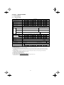
8.1.2
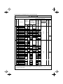
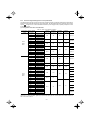
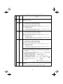
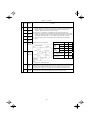
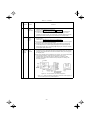
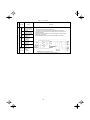
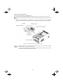
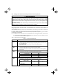
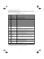
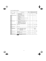
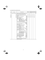
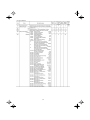
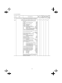
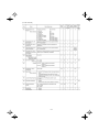
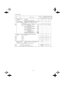
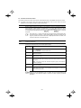
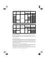
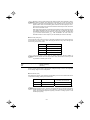
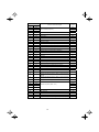
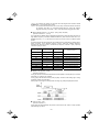
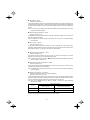
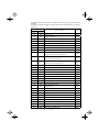
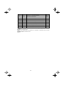
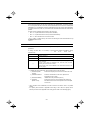
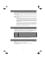
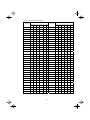
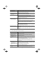
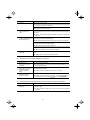
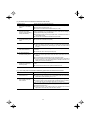
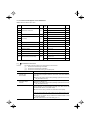
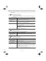
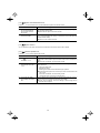
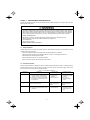
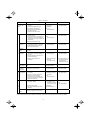
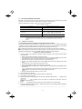
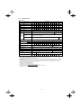
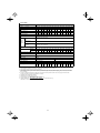
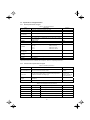
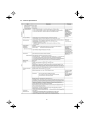
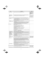
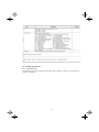
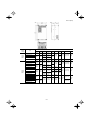
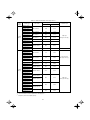
Three-phase 460 V
■ 1 to 75HP
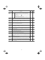
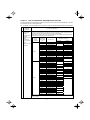
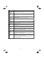
Item
Specifications
Type (FRN _ _ _ F1S-4U)
025
030
040
050
060
*1
1
2
3
5
7.5
10
15
20
25
30
40
50
60
75
Rated capacity 〔kVA〕
*2
1.9
2.9
4.3
7.1
9.9
13
18
23
29
35
47
57
67
83
Rated voltage 〔V〕
*3 Three-phase, 380 to 480V (With AVR function)
Rated current 〔A〕
*4
30
37
44
59
72
85
105
Output ratings
020
Nominal applied motor 〔HP〕
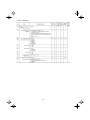
Input ratings
002
003
005
007
010
015
2.5
3.7
5.5
9.0
12.5 16.5
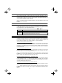
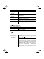
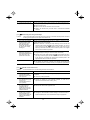
Overload capability
120% of rated current for 1min.
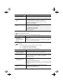
Rated frequency
50, 60Hz
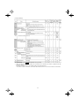
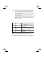
Main power supply
Auxiliary fan
power input
Single-phase,
380 to 440V/50Hz
Single-phase,
380 to 480V/60Hz
Voltage/frequency variations
Voltage: +10 to -15% (Voltage unbalance 2% or less) *9, Frequency: +5% to -5%
(with DCR)
1.3
2.5
3.8
6.2
8.9
11.8 17.7 23.7 29.6 35.5 46.8 57.0 68.4
85.7
(without DCR)
2.5
4.8
6.9
10.8
14.5 19.1 27.7 36.0 43.6 50.9 64.0 78.5 93.7
118
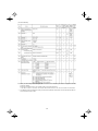
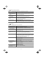
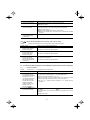
Required power supply capacity 〔kVA〕 *7
1.1
2.0
3.1
5.0
7.1
69
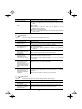
Torque 〔%〕
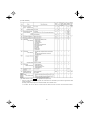
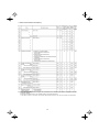
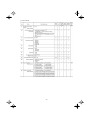
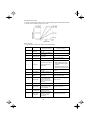
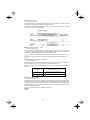
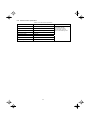
DC injection braking
10
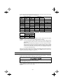
Enclosure (IEC60529)
IP20, UL open type
Mass 〔lbs(kg)〕
*9
19
24
29
38
46
55
10 to 15
Starting frequency: 0.0 to 60.0Hz, Braking time:0.0 to 30.0s, Braking level: 0 to 60%
Option
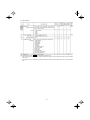
Cooling method
15
20
*8
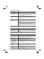
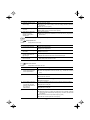
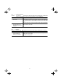
UL508C, C22.2 No.14, EN50178-1997
*5
Three-phase, 380 to 440V, 50Hz
Three-phase, 380 to 480V, 60Hz
*5 None
Applicable safety standards
*6
*7
*8
075
Single-phase, 380 to 480V, 50/60Hz
DC reactor (DCR)
*1
*2
*3
*4
23
Three-phase, 380 to 480V, 50/60Hz
Phases,
Auxiliary control
voltage,
power input
frequency
Rated current 〔A〕 *6
Braking
001
Natural
cooling
IP00, UL open type
Fan cooling
6.8
7.1
7.3
7.5
7.5
13
13
15
22
22
25
51
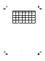
(3.1) (3.2) (3.3) (3.4) (3.4) (6.0) (6.0) (6.9) (9.9) (9.9) (11.5) (23)
53
(24)
73
(33)
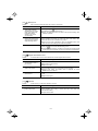
Standard 4-pole motor
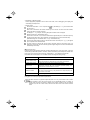
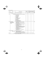
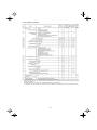
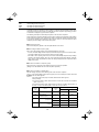
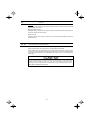
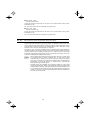
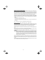
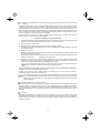
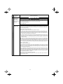
Rated capacity is calculated by assuming the output rated voltage as 460V for three-phase 460V.
Output voltage cannot exceed the power supply voltage.
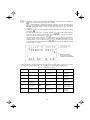
An excessively low setting of the carrier frequency may result in the higher motor temperature or tripping of the inverter by its overcurrent
limiter setting. Lower the continuous load or maximum load instead. (When setting the carrier frequency (F26) to 1kHz, reduce the load to
80% of its rating.)
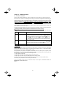
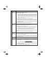
Use [R1,T1] terminals for driving AC cooling fans of an inverter powered by the DC link bus, such as by a high power factor PWM
converter. (In ordinary operation, the terminals are not used.)
Calculated under Fuji-specified conditions.
Obtained when a DC reactor (DCR) is used.
Average braking torque (Varies with the efficiency of the motor.)
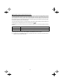
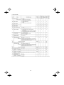
Max. voltage(V) - Min. voltage(V)
Voltage unbalance(%)=
×67(IEC61800-3(5.2.3))
Three-phase average voltage(V)
If this value is 2 to 3%, use an AC reactor (ACR).
8-2