1
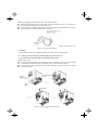
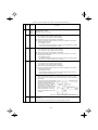
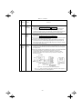
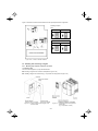
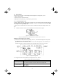
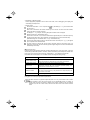
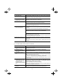
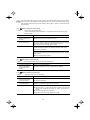
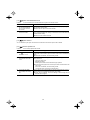
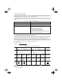
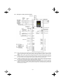
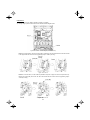
DC link bus terminals, P (+) and N (-)
These are provided for the DC link bus powered system. Connect these terminals with terminals P(+) and N (-)
of other inverters.
Consult your Fuji Electric representative if these terminals are to be used.
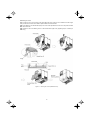
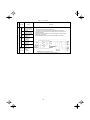
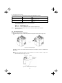
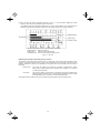
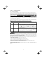
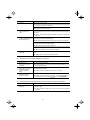
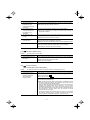
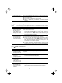
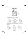
Main circuit power input terminals, L1/R, L2/S, and L3/T (three-phase input)
1) For safety, make sure that the molded case circuit breaker (MCCB) or magnetic contactor (MC) is turned off
before wiring the main circuit power input terminals.
2) Connect the main circuit power supply wires (L1/R, L2/S and L3/T) to the input terminals of the inverter via
an MCCB or residual-current-operated protective device (RCD)/a ground fault circuit interrupter (GFCI)*,
and MC if necessary.
It is not necessary to align phases of the power supply wires and the input terminals of the inverter with
each other.
* With overcurrent protection
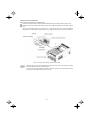
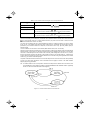
It is recommended that a magnetic contactor be inserted that can be manually activated. This is to
allow you to disconnect the inverter from the power supply in an emergency (e.g., when the protective
function is activated) so as to prevent a failure or accident from causing the secondary problems.
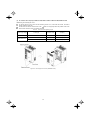
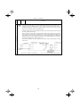
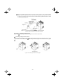
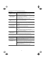
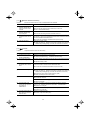
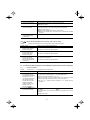
Auxiliary power input terminals R0 and T0 for the control circuit
In general, the inverter will run normally without power supplied to the auxiliary power input for the control circuit.
However, if you share the input power for the control circuit with that for the main circuit, you would be lost when,
in the event of an error or alarm, you turn OFF the magnetic contactor between the inverter and the commercial
power supply. If the magnetic contactor is turned OFF, the input power to the control circuit is shut OFF, causing
the alarm signals (30A/B/C) to be lost and the display on the keypad to disappear. To secure input power to the
control circuit at all times, supply the power from the primary side of the magnetic contactor to control power
auxiliary input terminals R0 and T0.
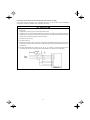
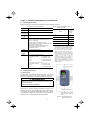
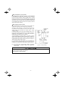
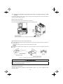
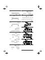
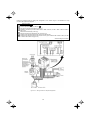
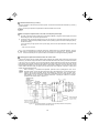
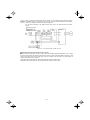
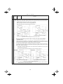
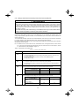
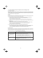
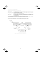
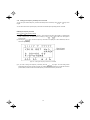
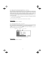
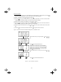
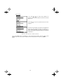
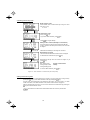
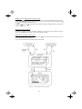
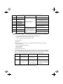
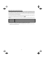
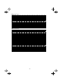
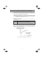
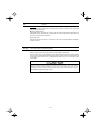
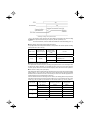
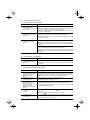
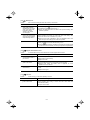
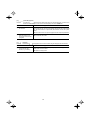
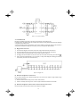
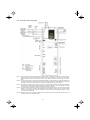
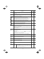
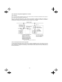
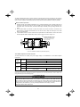
When introducing a residual-current-operated protective device (RCD)/ground fault circuit
interrupter (GFCI), connect its output (secondary) side to terminals R0 and T0. Connecting its input
(primary) side to those terminals causes the RCD/GFCI to malfunction since the input power
voltage to the inverter is three-phase but the one to terminals R0 and T0 is single-phase. To avoid
such problems, be sure to insert an insulation transformer or auxiliary B contacts of a magnetic
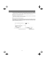
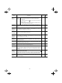
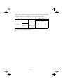
contactor in the location shown in Figure 2.17.
Ground fault
circuit interrupter
Figure 2.17 Connection Example of residual-current-operated protective device (RCD)/
Ground Fault Circuit Interrupter (GFCI)
2-22